EP3246615B1 - A mounting assembly - Google Patents
A mounting assembly Download PDFInfo
- Publication number
- EP3246615B1 EP3246615B1 EP16170526.4A EP16170526A EP3246615B1 EP 3246615 B1 EP3246615 B1 EP 3246615B1 EP 16170526 A EP16170526 A EP 16170526A EP 3246615 B1 EP3246615 B1 EP 3246615B1
- Authority
- EP
- European Patent Office
- Prior art keywords
- locking
- arm
- mounting assembly
- housing
- base
- Prior art date
- Legal status (The legal status is an assumption and is not a legal conclusion. Google has not performed a legal analysis and makes no representation as to the accuracy of the status listed.)
- Active
Links
- 238000006073 displacement reaction Methods 0.000 claims description 19
- 238000012544 monitoring process Methods 0.000 claims description 10
- 230000004044 response Effects 0.000 claims description 9
- 239000004020 conductor Substances 0.000 claims description 5
- 239000002184 metal Substances 0.000 claims description 5
- 238000010276 construction Methods 0.000 description 20
- 239000000463 material Substances 0.000 description 14
- 230000007246 mechanism Effects 0.000 description 14
- 230000008901 benefit Effects 0.000 description 4
- 230000000712 assembly Effects 0.000 description 3
- 238000000429 assembly Methods 0.000 description 3
- 230000008878 coupling Effects 0.000 description 3
- 238000010168 coupling process Methods 0.000 description 3
- 238000005859 coupling reaction Methods 0.000 description 3
- 230000009286 beneficial effect Effects 0.000 description 2
- 230000003993 interaction Effects 0.000 description 2
- NJPPVKZQTLUDBO-UHFFFAOYSA-N novaluron Chemical compound C1=C(Cl)C(OC(F)(F)C(OC(F)(F)F)F)=CC=C1NC(=O)NC(=O)C1=C(F)C=CC=C1F NJPPVKZQTLUDBO-UHFFFAOYSA-N 0.000 description 2
- 230000000007 visual effect Effects 0.000 description 2
- 229910000831 Steel Inorganic materials 0.000 description 1
- 230000004888 barrier function Effects 0.000 description 1
- 239000011248 coating agent Substances 0.000 description 1
- 238000000576 coating method Methods 0.000 description 1
- 239000003292 glue Substances 0.000 description 1
- 230000001939 inductive effect Effects 0.000 description 1
- 230000004048 modification Effects 0.000 description 1
- 238000012986 modification Methods 0.000 description 1
- 238000003908 quality control method Methods 0.000 description 1
- 239000010959 steel Substances 0.000 description 1
Images


Classifications
-
- G—PHYSICS
- G08—SIGNALLING
- G08B—SIGNALLING OR CALLING SYSTEMS; ORDER TELEGRAPHS; ALARM SYSTEMS
- G08B13/00—Burglar, theft or intruder alarms
- G08B13/18—Actuation by interference with heat, light, or radiation of shorter wavelength; Actuation by intruding sources of heat, light, or radiation of shorter wavelength
- G08B13/189—Actuation by interference with heat, light, or radiation of shorter wavelength; Actuation by intruding sources of heat, light, or radiation of shorter wavelength using passive radiation detection systems
- G08B13/194—Actuation by interference with heat, light, or radiation of shorter wavelength; Actuation by intruding sources of heat, light, or radiation of shorter wavelength using passive radiation detection systems using image scanning and comparing systems
- G08B13/196—Actuation by interference with heat, light, or radiation of shorter wavelength; Actuation by intruding sources of heat, light, or radiation of shorter wavelength using passive radiation detection systems using image scanning and comparing systems using television cameras
- G08B13/19617—Surveillance camera constructional details
- G08B13/19632—Camera support structures, e.g. attachment means, poles
-
- H—ELECTRICITY
- H01—ELECTRIC ELEMENTS
- H01R—ELECTRICALLY-CONDUCTIVE CONNECTIONS; STRUCTURAL ASSOCIATIONS OF A PLURALITY OF MUTUALLY-INSULATED ELECTRICAL CONNECTING ELEMENTS; COUPLING DEVICES; CURRENT COLLECTORS
- H01R13/00—Details of coupling devices of the kinds covered by groups H01R12/70 or H01R24/00 - H01R33/00
- H01R13/62—Means for facilitating engagement or disengagement of coupling parts or for holding them in engagement
- H01R13/639—Additional means for holding or locking coupling parts together, after engagement, e.g. separate keylock, retainer strap
-
- F—MECHANICAL ENGINEERING; LIGHTING; HEATING; WEAPONS; BLASTING
- F16—ENGINEERING ELEMENTS AND UNITS; GENERAL MEASURES FOR PRODUCING AND MAINTAINING EFFECTIVE FUNCTIONING OF MACHINES OR INSTALLATIONS; THERMAL INSULATION IN GENERAL
- F16C—SHAFTS; FLEXIBLE SHAFTS; ELEMENTS OR CRANKSHAFT MECHANISMS; ROTARY BODIES OTHER THAN GEARING ELEMENTS; BEARINGS
- F16C11/00—Pivots; Pivotal connections
- F16C11/04—Pivotal connections
- F16C11/06—Ball-joints; Other joints having more than one degree of angular freedom, i.e. universal joints
- F16C11/0619—Ball-joints; Other joints having more than one degree of angular freedom, i.e. universal joints the female part comprising a blind socket receiving the male part
- F16C11/0623—Construction or details of the socket member
-
- F—MECHANICAL ENGINEERING; LIGHTING; HEATING; WEAPONS; BLASTING
- F16—ENGINEERING ELEMENTS AND UNITS; GENERAL MEASURES FOR PRODUCING AND MAINTAINING EFFECTIVE FUNCTIONING OF MACHINES OR INSTALLATIONS; THERMAL INSULATION IN GENERAL
- F16M—FRAMES, CASINGS OR BEDS OF ENGINES, MACHINES OR APPARATUS, NOT SPECIFIC TO ENGINES, MACHINES OR APPARATUS PROVIDED FOR ELSEWHERE; STANDS; SUPPORTS
- F16M11/00—Stands or trestles as supports for apparatus or articles placed thereon ; Stands for scientific apparatus such as gravitational force meters
- F16M11/02—Heads
- F16M11/04—Means for attachment of apparatus; Means allowing adjustment of the apparatus relatively to the stand
- F16M11/06—Means for attachment of apparatus; Means allowing adjustment of the apparatus relatively to the stand allowing pivoting
- F16M11/12—Means for attachment of apparatus; Means allowing adjustment of the apparatus relatively to the stand allowing pivoting in more than one direction
- F16M11/14—Means for attachment of apparatus; Means allowing adjustment of the apparatus relatively to the stand allowing pivoting in more than one direction with ball-joint
-
- F—MECHANICAL ENGINEERING; LIGHTING; HEATING; WEAPONS; BLASTING
- F16—ENGINEERING ELEMENTS AND UNITS; GENERAL MEASURES FOR PRODUCING AND MAINTAINING EFFECTIVE FUNCTIONING OF MACHINES OR INSTALLATIONS; THERMAL INSULATION IN GENERAL
- F16M—FRAMES, CASINGS OR BEDS OF ENGINES, MACHINES OR APPARATUS, NOT SPECIFIC TO ENGINES, MACHINES OR APPARATUS PROVIDED FOR ELSEWHERE; STANDS; SUPPORTS
- F16M11/00—Stands or trestles as supports for apparatus or articles placed thereon ; Stands for scientific apparatus such as gravitational force meters
- F16M11/20—Undercarriages with or without wheels
- F16M11/2007—Undercarriages with or without wheels comprising means allowing pivoting adjustment
- F16M11/2021—Undercarriages with or without wheels comprising means allowing pivoting adjustment around a horizontal axis
- F16M11/2028—Undercarriages with or without wheels comprising means allowing pivoting adjustment around a horizontal axis for rolling, i.e. for creating a landscape-portrait rotation
-
- F—MECHANICAL ENGINEERING; LIGHTING; HEATING; WEAPONS; BLASTING
- F16—ENGINEERING ELEMENTS AND UNITS; GENERAL MEASURES FOR PRODUCING AND MAINTAINING EFFECTIVE FUNCTIONING OF MACHINES OR INSTALLATIONS; THERMAL INSULATION IN GENERAL
- F16M—FRAMES, CASINGS OR BEDS OF ENGINES, MACHINES OR APPARATUS, NOT SPECIFIC TO ENGINES, MACHINES OR APPARATUS PROVIDED FOR ELSEWHERE; STANDS; SUPPORTS
- F16M13/00—Other supports for positioning apparatus or articles; Means for steadying hand-held apparatus or articles
- F16M13/02—Other supports for positioning apparatus or articles; Means for steadying hand-held apparatus or articles for supporting on, or attaching to, an object, e.g. tree, gate, window-frame, cycle
-
- G—PHYSICS
- G03—PHOTOGRAPHY; CINEMATOGRAPHY; ANALOGOUS TECHNIQUES USING WAVES OTHER THAN OPTICAL WAVES; ELECTROGRAPHY; HOLOGRAPHY
- G03B—APPARATUS OR ARRANGEMENTS FOR TAKING PHOTOGRAPHS OR FOR PROJECTING OR VIEWING THEM; APPARATUS OR ARRANGEMENTS EMPLOYING ANALOGOUS TECHNIQUES USING WAVES OTHER THAN OPTICAL WAVES; ACCESSORIES THEREFOR
- G03B17/00—Details of cameras or camera bodies; Accessories therefor
- G03B17/56—Accessories
- G03B17/561—Support related camera accessories
-
- G—PHYSICS
- G08—SIGNALLING
- G08B—SIGNALLING OR CALLING SYSTEMS; ORDER TELEGRAPHS; ALARM SYSTEMS
- G08B13/00—Burglar, theft or intruder alarms
- G08B13/18—Actuation by interference with heat, light, or radiation of shorter wavelength; Actuation by intruding sources of heat, light, or radiation of shorter wavelength
- G08B13/189—Actuation by interference with heat, light, or radiation of shorter wavelength; Actuation by intruding sources of heat, light, or radiation of shorter wavelength using passive radiation detection systems
- G08B13/194—Actuation by interference with heat, light, or radiation of shorter wavelength; Actuation by intruding sources of heat, light, or radiation of shorter wavelength using passive radiation detection systems using image scanning and comparing systems
- G08B13/196—Actuation by interference with heat, light, or radiation of shorter wavelength; Actuation by intruding sources of heat, light, or radiation of shorter wavelength using passive radiation detection systems using image scanning and comparing systems using television cameras
- G08B13/19617—Surveillance camera constructional details
-
- H—ELECTRICITY
- H01—ELECTRIC ELEMENTS
- H01R—ELECTRICALLY-CONDUCTIVE CONNECTIONS; STRUCTURAL ASSOCIATIONS OF A PLURALITY OF MUTUALLY-INSULATED ELECTRICAL CONNECTING ELEMENTS; COUPLING DEVICES; CURRENT COLLECTORS
- H01R13/00—Details of coupling devices of the kinds covered by groups H01R12/70 or H01R24/00 - H01R33/00
- H01R13/62—Means for facilitating engagement or disengagement of coupling parts or for holding them in engagement
- H01R13/639—Additional means for holding or locking coupling parts together, after engagement, e.g. separate keylock, retainer strap
- H01R13/6395—Additional means for holding or locking coupling parts together, after engagement, e.g. separate keylock, retainer strap for wall or panel outlets
-
- E—FIXED CONSTRUCTIONS
- E05—LOCKS; KEYS; WINDOW OR DOOR FITTINGS; SAFES
- E05B—LOCKS; ACCESSORIES THEREFOR; HANDCUFFS
- E05B9/00—Lock casings or latch-mechanism casings ; Fastening locks or fasteners or parts thereof to the wing
- E05B9/08—Fastening locks or fasteners or parts thereof, e.g. the casings of latch-bolt locks or cylinder locks to the wing
-
- F—MECHANICAL ENGINEERING; LIGHTING; HEATING; WEAPONS; BLASTING
- F16—ENGINEERING ELEMENTS AND UNITS; GENERAL MEASURES FOR PRODUCING AND MAINTAINING EFFECTIVE FUNCTIONING OF MACHINES OR INSTALLATIONS; THERMAL INSULATION IN GENERAL
- F16M—FRAMES, CASINGS OR BEDS OF ENGINES, MACHINES OR APPARATUS, NOT SPECIFIC TO ENGINES, MACHINES OR APPARATUS PROVIDED FOR ELSEWHERE; STANDS; SUPPORTS
- F16M2200/00—Details of stands or supports
- F16M2200/02—Locking means
- F16M2200/021—Locking means for rotational movement
- F16M2200/024—Locking means for rotational movement by positive interaction, e.g. male-female connections
-
- G—PHYSICS
- G03—PHOTOGRAPHY; CINEMATOGRAPHY; ANALOGOUS TECHNIQUES USING WAVES OTHER THAN OPTICAL WAVES; ELECTROGRAPHY; HOLOGRAPHY
- G03B—APPARATUS OR ARRANGEMENTS FOR TAKING PHOTOGRAPHS OR FOR PROJECTING OR VIEWING THEM; APPARATUS OR ARRANGEMENTS EMPLOYING ANALOGOUS TECHNIQUES USING WAVES OTHER THAN OPTICAL WAVES; ACCESSORIES THEREFOR
- G03B17/00—Details of cameras or camera bodies; Accessories therefor
-
- H—ELECTRICITY
- H04—ELECTRIC COMMUNICATION TECHNIQUE
- H04N—PICTORIAL COMMUNICATION, e.g. TELEVISION
- H04N7/00—Television systems
- H04N7/18—Closed-circuit television [CCTV] systems, i.e. systems in which the video signal is not broadcast
Definitions
- the invention relates to a mounting assembly for an electronic device. Specifically, the invention relates to the arrangement of an attachment part, an arm and a base of the mounting assembly.
- a mounting assembly can be provided for many different types of devices.
- US 8,998,512 B1 discloses an articulating camera arm and a camera assembly comprising the articulating camera arm.
- the articulating camera arm may be locked in position by a set screw.
- US 2008/251675 A1 discloses a rotating pedestal with an integrated locking mechanism configured to lock the pedestal in a desired angular position.
- This patent application relates to a mounting assembly provided for an electronic device.
- the electronic device is attached to an attachment part of the mounting assembly.
- the attachment part is in turn coupled to an arm which in turn is coupled to a base.
- the base may be arranged on, and optionally fastened to, a surface such as a wall, table or a ceiling.
- the mounting assembly may be arranged for allowing the attachment part, and thus the electronic device attached thereto, to be moved relative the arm by for example a tilt and/or a rotational movement.
- the arm can be arranged to be rotationally movable relative the base.
- the mounting assembly may be constructed to provide a locking of the movement of its parts relative each other, i.e. the arm relative the base and the attachment part, respectively.
- One type of locking construction is to utilize friction force created in the interface between parts, such as in the interface between the arm and the base.
- the mounting assembly may be arranged such that a part of the arm is forced against a part of the base so as to create a tight arrangement. The resulting friction force created by the tight arrangement counteracts movement of the arm in relation to the base.
- a rotational movement of the arm in relation to the base may be restricted.
- a solution to this problem is to provide a friction-increasing material, such as glue material or a friction coating, in the interface between the parts.
- the friction-increasing material may increase the ratio between the created friction force and how tight the tight arrangement between the parts must be in order to achieve such a friction force.
- a problem with friction-increasing materials is that they may be difficult to apply to certain material surfaces and a high level of quality control may be required. Moreover, the friction-increasing material may wear off over time which is difficult to both discover and take care of since the interface is typically not visible without disassembling the mounting assembly.
- the friction-inducing material provides an undesired nonconductive barrier which may obstruct the conducting path.
- a cable of the electronic device attached to the attachment part may be arranged to extend through the parts of the mounting assembly, i.e. through the attachment part, the arm, and the base.
- it may be desirable to limit the rotational movement of the parts relative each other.
- An unlimited rotational movement of the parts relative each other may cause a problem in that the cable may be twisted beyond function, be sheared off, or a continuous rotation may dislodge connectors thereof.
- the mounting assembly comprises an attachment part arranged to be attached to the electronic device; a base arranged to be attached to a mounting surface; and an arm via which the attachment part is connected to the base.
- the attachment part is coupled to the arm such that the attachment part is lockingly tiltable relative the arm.
- the arm is coupled to the base such that the arm is lockingly rotatable relative the base about a rotational axis that is parallel with a longitudinal axis of the arm.
- the arm comprises a housing; and a locking member arranged inside the housing and being provided with a locking protrusion.
- the locking member is coupled to the housing via an adjustment element such that the locking member is displaceable relative the housing, and such that the locking protrusion is radially displaceable in relation to the rotational axis, by adjusting said adjustment member.
- the base is provided with a set of radially extending locking grooves in relation to the rotational axis.
- the mounting assembly is arranged such that the locking protrusion is received by one locking groove in the set of locking grooves in response to a displacement of the locking member, and thus a radial displacement of the locking protrusion, relative the housing, whereby the arm is rotationally locked in relation to the base.
- the locking member is displaceable relative the housing for adjustment between a locked mode and an unlocked mode in view of rotational movement of the arm relative the base.
- the locking protrusion is arranged on the locking member such that the locking protrusion is radially displaced in view of the rotational axis when the locking member is displaced.
- the mounting assembly is arranged such that when the locking member is displaced relative the housing, and thus the locking protrusion is radially displaced relative the rotational axis, the locking protrusion of the locking member slides into and is received by a locking groove of the base. By that the locking grooves extends radially, a rotational movement of the locking member, and thus the arm, is prevented when the locking protrusion is received in any of the locking grooves.
- the inventive locking mechanism provided for rotationally locking the arm in relation to the base at least reduces the need for friction-induced materials in the interface between the arm and the base.
- a mechanical lock is provided, a higher level of stability and robustness of the mounting assembly is achieved by that the locking mechanism does not solely rely on a friction force provided by the friction-induced material.
- the inventive construction may also become more resistant to wear.
- a typical configuration of the mounting assembly may enable a small rotational movement even in the locked mode, due to a difference in dimensions of the locking protrusion and the locking groove in which the locking protrusion is received.
- the locking mechanism is combinable with the usage of conductive materials for providing a conductive path between the arm and the base.
- the locking member, (parts of) the base and (parts of) the adjustment member may be made in a conductive material, such as steel, for providing a conductive path between the adjustment member and (parts of) the base.
- the locking protrusion may be provided on a surface of the locking member facing the base.
- the set of locking grooves of the base may be arranged as a circular array of radially extending grooves.
- the set of locking grooves may be connected by a guiding groove arranged to receive the locking protrusion.
- the mounting assembly may be arranged such that a joint member of the attachment part is positionally locked in relation to the arm in response to the displacement of the locking member relative the housing.
- the mounting assembly may be arranged such that the joint member is positionally locked relative the arm by clamping the joint member between a wedge member and the housing of the arm.
- the wedge member may be arranged inside the housing. Abutting surface portions of the locking member and of the wedge member may be inclined such that the wedge member is forced towards the joint member in response to the displacement of the locking member relative the housing for clamping the joint member.
- the attachment part may be coupled to the arm such that the attachment part is also lockingly rotatable relative the arm.
- the attachment part may be coupled to the arm via a ball joint.
- a ball joint typically allows both tilt movement and rotational movement.
- the radial displacement of the locking protrusion may be defined as a radial outwards displacement in relation to the rotational axis.
- the adjustment element may be a screw.
- the screw may be arranged to be accessible from outside the housing for adjustment.
- the locking member may be provided with an additional locking protrusion.
- the locking member may be coupled to the housing via the adjustment element such that the locking member is displaceable relative the housing, and such that the additional locking protrusion is radially displaceable in relation to the rotational axis, by adjusting said adjustment member.
- the base may be provided with an additional set of radially extending locking grooves in relation to the rotational axis.
- the mounting assembly may be arranged such that the additional locking protrusion is received by one additional locking groove in the additional the set of locking grooves in response to a displacement of the locking member, and thus a radial displacement of the additional locking protrusion, relative the housing.
- the construction may become more resistant against rotational forces.
- This exemplified construction may be beneficial for mounting assemblies of larger dimensions.
- the locking element may be made of a conductive material such as metal.
- the mounting assembly may further comprise a rotation stop member arranged to limit the rotational movement of the arm relative the base.
- the rotational movement is preferably limited to slightly more than 360 degrees, i.e. a bit more than a full turn.
- the attachment part may be lockingly tiltable relative the arm in a range of about 90 degrees. In combination with allowing a rotational movement of the arm in relation to the base, preferably slightly more than one turn, a wide range of possible positions of the electronic device is allowed.
- the electronic device may be a monitoring camera, a thermal sensor, a door station, or a speaker.
- the invention relates to a system comprising an electronic device and a mounting assembly according to an embodiment of the first aspect.
- the above disclosed examples of configurations of the mounting assembly apply to the mounting assembly of the system as well.
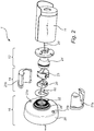
- Figure 1 illustrates a system 1 comprising an electronic device, in the form of a monitoring camera 11, and a mounting assembly 10.
- the monitoring camera 11 may comprise a visual or a thermal sensor for capturing visual or thermal images of a monitored scene.
- the mounting assembly 10 comprises a first part in the form of an attachment part 12, a second part in the form of an arm 14, and a third part in the form of a base 16.
- the monitoring camera 11 is attached to the attachment part 12 by screws or the like.
- a purpose of the construction of the mounting assembly 10 is to enable mounting of the electronic device, in this case the monitoring camera 11, to a surface 19.
- the surface 19 is in this example a wall, but could be a differently oriented surface such as a ceiling.
- Another purpose of the construction of the mounting assembly 10 is to enable setting and adjusting the position of the electronic device attached thereto.
- the attachment part 12 is coupled to the arm 14 such that the attachment part 12 is lockingly tiltable relative the arm 14.
- the attachment part 12, and the thereto attached monitoring camera 11, is thus allowed to tilt relative the arm 14 as indicated by 13.
- the attachment part 12 is allowed to tilt in an interval of 0 to about 90 degrees.
- the mounting assembly 10 is in this embodiment further arranged such that the attachment part 12, and thus also the monitoring camera 11, is allowed to rotate around a longitudinal axis 17 of the attachment part 12.
- the attachment part 12 is coupled to the arm 14 by means of a ball joint for enabling both tilt and rotational movements of the attachment part 12 in relation to the arm 14.
- Other types of joints may be utilized in the mounting assembly 10 for enabling a desired movement mechanism of the attachment part 12 in relation to the arm 14.
- the arm 14 is coupled to the base 16 such that the arm 14 is lockingly rotatable relative the base 16 about a rotational axis 18.
- the arm 14 is thus allowed to rotate relative the base 16 as indicated by 15.
- the rotational axis 18 is parallel with a longitudinal axis of the arm 14, and in the illustrated example these axes coincide.
- the mounting assembly 10 may be arranged so as to lock the possibility to move one or more of these parts relative each other.
- the respective movement of the attachment part 12 in relation to the arm 14 and of the arm 14 in relation to the base 16 may be locked by different locking mechanisms of the mounting assembly 10.
- one common locking mechanism is however arranged for locking both movements. This common locking mechanism will now be disclosed in detail with further reference to figure 2 .
- the system 1 is illustrated in an exploded view in figure 2 .
- a cable 29 for connecting the monitoring camera 11 to, for example, a power supply is arranged through the mounting assembly 10.
- the mounting assembly 10 may be arranged with a rotation stop mechanism in the joint between the attachment part 12 and the arm 14 for limiting the rotational movement of these parts relative each other for preventing twisting of the cable 29.
- the arm 14 comprises a housing which in this embodiment is formed by a first housing section 21a and a second housing section 21b. When joined, the first and second housing sections 21a, 21b form a housing having an overall cylindrical shape. Inside (within) the formed housing, a locking member 20 is arranged. The locking member 20 is arranged at one end of the housing. A lower surface of the locking member 20 faces towards the base 16.
- a wedge member 23 is also arranged inside (within) the housing. The wedge member 23 abuts the locking member 20.
- a joint member of the attachment part 12 is arranged.
- the joint member is in this embodiment formed by a ball 24 being part of the ball joint which couples the attachment part 12 to the arm 14.
- the wedge member 23 and the housing sections 21a, 21b are arranged to form a ball socket for receiving the ball 24 and for preventing removal of the ball 24 when arranged in the ball socket.
- the base 16 comprises a plate member 26 which is provided with holes 27a, 27b for attaching the base 16 to the surface 19.
- the base 16 further comprises a groove member 28.
- the groove member 28 is in this embodiment formed together with the plate member 26.
- the groove member 28 and the plate member 26 may for instance be casted or molded together. In other embodiments, the groove member 28 may form a separate part.
- a rotation stop member 60 is provided for enabling a rotation stop function of the arm 14 in relation to the base 16. The design and function of the rotation stop member 60 will be explained in detail in connection to figure 5 .
- the groove member 28 is provided with a set of locking grooves 22.
- the set of locking grooves 22 are arranged as a circular array.
- the locking grooves 22 are provided to extend radially in view of the rotational axis 18 of the arm 14, when the mounting assembly 10 is assembled.
- the housing sections 21a, 21b are arranged to engage with a part of the base, when the housing sections 21a, 21b are joined to form the housing, such that the arm 14 is rotationally fixed to the base 16.
- the mounting assembly 10 is arranged such that the arm 14 is fixed in view of movement along the longitudinal axis of the arm 14. This attachment may be achieved by different constructions of the arm and the base which are known and achievable for the skilled person.
- the locking is provided by an interaction between the locking member 20 and the groove member 28.
- the locking member 20 is provided with a locking protrusion 30.
- the locking protrusion 30 is in this embodiment provided on a surface which faces the groove member 28 and thus the base 16.
- the locking member 20 is arranged to be coupled to the housing, and in this embodiment to the first housing section 21a.
- the coupling is provided by an adjustment member in the form of a screw 32 which may be adjusted as indicated by 33.
- the screw 33 is arranged to be accessible from outside the housing whereby adjustment can be performed without disassembling the mounting assembly.
- the screw 32 is arranged through a hole 35 of the housing section 21a and further through a threaded hole 31 of the locking member 20.
- the screw 32 is provided for adjusting the position of the locking member 20 in relation to the housing, and in this embodiment in relation to the first housing section 21a.
- the position of the locking protrusion 30 as seen in a radial direction to the rotational axis 18, which in this embodiment is the same as the longitudinal axis of the housing and the arm, is made adjustable by the screw 32.
- the locking member 20 is displaceable relative the housing, and thereby the locking protrusion 30 is radially displaceable in relation to the rotational axis 18, by adjustment of the screw 32.
- the displacement of the locking member 20 is indicated by 34.
- FIG. 4a The interaction between the locking member 20 and the groove member 28 is illustrated in figures 4a and 4b .
- the locking protrusion 30 has been displaced radially outwards from the rotational axis 18, and thus towards the housing, such that the locking protrusion 30 is received by one locking groove 22a in the set of locking grooves 22.
- the displacement of the locking protrusion 30 is achieved by adjustment of the locking member's 20 position relative the housing by means of the screw 32 as previously disclosed. With the locking protrusion 30 in this position, a locked mode of the arm 14 in relation to the base 16 is achieved.
- the locking protrusion 30 has been radially displaced inwards towards the rotational axis 18, as indicated by 41.
- an unlocked mode of the arm 14 in relation to the base 16 is achieved.
- the locking member 20, and thus the arm 14, is allowed to rotate in relation to the base 16.
- the locking protrusion 30 is in this unlocked mode received in a guiding groove 40 of the groove member 28.
- the guiding groove 40 is in this embodiment open towards the inner area of the groove member 28.
- the set of locking grooves 22 are provided close to each other with a relatively small gap between entrances of adjacent locking grooves, as seen from the guiding groove 40, for facilitating the receipt of the locking protrusion 30.
- the arm 14 may be rotated in relation to the groove member 28 and thus to the base 16 from a first position to a second position.
- the locking member 20 may again be displaced by adjustment of the screw 32, whereby the locking protrusion 30 is displaced radially outwards from the rotational axis 18 and received in a second locking groove in the set of locking grooves 22.
- the second locking groove may be another than the locking groove 22a of figure 4b .
- Different rotational positions of the arm 14 in relation to the base 16 may thus be fixed in view of rotational movement.
- abutting surface portions of the wedge member 23 and of the locking member 20 are inclined in a corresponding manner. Specifically, the abutting surface portions are inclined such that the wedge member 23 is forced upwards towards the ball 24 in response to the displacement of the locking member 20 towards the housing.
- the wedge member 23 is forced towards the ball 24, and by the construction of the ball socket, the ball 24 is clamped between the wedge member 23 and the housing.
- any movement of the ball 24, and thus of the attachment part 12 is locked.
- the ball 24 can neither rotate nor tilt in relation to the arm 14 when the mounting assembly 10 is arranged in this mode.
- the inclined surface portions of the wedge member 23 and the locking member 20 do not need to abut.
- the desired function of forcing the wedge member 23 so as to clamp the joint member may be achieved by other constructions as well.
- an intermediate member between the wedge member 23 and the locking member 20 may be provided.
- Alternative configurations are apparent for the skilled person.
- both the movement of the attachment part 12 in relation to the arm 14, and the movement of the arm 14 in relation to the base 16 may be locked by a single locking adjustment, that is the adjustment of the screw 33 for displacing the locking member 20 relative the housing.
- movement of the parts of the mounting assembly 10 may be enabled by a single unlocking adjustment wherein the locking member 20 is displaced the reverse direction.
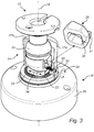
- Figure 5 illustrates parts of the mounting assembly of figure 2 .
- the rotation stop member 60 is provided between the locking member 20 and the groove member 28.
- the rotation stop member 60 has the overall shape of a plate.
- a first protrusion 64 is provided for operatively connecting the rotation stop member 60 to the locking member 20 such that the rotation stop member 60 rotates together with the locking member 20.
- the first protrusion 64 may be received in an opening or groove provided in the surface (of the locking member 20) facing the rotation stop member 60.
- a second protrusion 61 is arranged to protrude and run along an inner surface 65 of the groove member 28.
- a stop element 63 is provided along the inner surface 65 of the groove member 28 and arranged to prevent the second protrusion 61 from passing during rotation.
- a gap 62 is provided on the rotation stop member 60 for allowing the locking protrusion 30 to reach the groove member 28 and in particular the set of locking grooves 22.
- the gap 62 is designed to be larger in cross-section than the locking protrusion 30 for providing flexibility in the rotational movement of the locking member 20 in relation to the rotation stop member 60.
- the locking member 20 is thereby allowed to rotate a bit further, corresponding to a distance set by the dimension of the gap 62 in relation to the dimension of the locking protrusion 30, when the second protrusion 61 meets the stop element 63 and is prevented from further rotation.
- This construction allows the locking member 20 to rotate in a rotational range of a bit more than a full turn, i.e. slightly more than 360 degrees.
- the parts of the mounting assembly 10 Different materials may be used for the parts of the mounting assembly 10.
- at least the locking member 20, the adjustment member being exemplified as a screw 32, and the groove member 28 are made in metal.
- a conductive path may thereby be achieved running from the screw 33, through the locking member 20, and to the groove member 28.
- the locking member 20 and the adjustment member may then easily be grounded, which is an advantage for fulfilling device regulations such as EMC, EMS or ECD regulations.
- the locking member may be provided with more than one locking protrusion.
- the locking member may be provided with a (first) locking protrusion in accordance with above disclosed embodiments, and further with an additional (second) locking protrusion.
- the groove member is in such an embodiment provided with a plurality of sets of locking grooves.
- the groove member may be provided with a (first) set of locking grooves in accordance with above disclosed embodiments, and further with an additional (second) set of locking grooves.
- the locking member may thus be provided with a first locking protrusion and a second locking protrusion.
- the first and second locking protrusions may be aligned and located radially at different distances from the rotational axis of the arm.
- the locking protrusions may be provided on a surface facing the groove member and in particular facing the plurality of sets of locking grooves thereof.
- the locking mechanism of the arm in relation to the base follows the same principle as in the above disclosed embodiments.
- the locking member is displaced in relation to a housing of the arm, by adjustment of e.g. a screw, the locking protrusions are radially displaced in view of the rotational axis of the arm.
- Each of the locking protrusions is received in one locking groove in the respective set of locking grooves.
- the locking member, and thus the arm is fixed in view of rotation movement and in relation to the groove member, and thus the base.
- attachment part 12, arm 14, and base 16 are provided for facilitating the understanding of the description of the different embodiments of the mounting assembly.
- the construction of the claimed mounting assembly is however not dependant on the use of this division of its parts (attachment part, arm, base) and the components (e.g. locking member, wedge member, joint member, groove member) that are disclosed as being comprised in each part. It should thus be realized that many different configurations of the mounting assembly are possible within the scope of the claims and are apparent for the skilled person to achieve.
- the locking construction of the mounting assembly as exemplified above may be constructed in a reverse manner wherein the base comprises locking member and the arm comprises the groove member with the set of locking grooves.
- the coupling between the attachment part and the arm may be achieved by alternative constructions to the ones exemplified above.
- the coupling could be provided for allowing the attachment part to tilt relative the arm without allowing rotational movement.
- the mounting assembly may be designed with a locking protrusion provided on a side surface of the locking member. A combination of these examples may also be feasible.
Landscapes
- Engineering & Computer Science (AREA)
- General Engineering & Computer Science (AREA)
- Mechanical Engineering (AREA)
- Physics & Mathematics (AREA)
- General Physics & Mathematics (AREA)
- Accessories Of Cameras (AREA)
- Studio Devices (AREA)
- Pivots And Pivotal Connections (AREA)
- Casings For Electric Apparatus (AREA)
Priority Applications (6)
| Application Number | Priority Date | Filing Date | Title |
|---|---|---|---|
| EP16170526.4A EP3246615B1 (en) | 2016-05-20 | 2016-05-20 | A mounting assembly |
| KR1020170053745A KR101863851B1 (ko) | 2016-05-20 | 2017-04-26 | 장착 어셈블리 |
| CN201710282010.2A CN107404046B (zh) | 2016-05-20 | 2017-04-26 | 安装组件 |
| US15/584,220 US9940802B2 (en) | 2016-05-20 | 2017-05-02 | Mounting assembly |
| TW106115082A TWI700457B (zh) | 2016-05-20 | 2017-05-08 | 安裝組件 |
| JP2017095213A JP6356310B2 (ja) | 2016-05-20 | 2017-05-12 | 取り付けアセンブリ |
Applications Claiming Priority (1)
| Application Number | Priority Date | Filing Date | Title |
|---|---|---|---|
| EP16170526.4A EP3246615B1 (en) | 2016-05-20 | 2016-05-20 | A mounting assembly |
Publications (2)
| Publication Number | Publication Date |
|---|---|
| EP3246615A1 EP3246615A1 (en) | 2017-11-22 |
| EP3246615B1 true EP3246615B1 (en) | 2018-05-02 |
Family
ID=56068726
Family Applications (1)
| Application Number | Title | Priority Date | Filing Date |
|---|---|---|---|
| EP16170526.4A Active EP3246615B1 (en) | 2016-05-20 | 2016-05-20 | A mounting assembly |
Country Status (6)
| Country | Link |
|---|---|
| US (1) | US9940802B2 (ko) |
| EP (1) | EP3246615B1 (ko) |
| JP (1) | JP6356310B2 (ko) |
| KR (1) | KR101863851B1 (ko) |
| CN (1) | CN107404046B (ko) |
| TW (1) | TWI700457B (ko) |
Families Citing this family (21)
| Publication number | Priority date | Publication date | Assignee | Title |
|---|---|---|---|---|
| TWD186432S (zh) * | 2016-03-15 | 2017-11-01 | 安訊士有限公司 | 監視攝影機 |
| USD818518S1 (en) * | 2016-03-31 | 2018-05-22 | Axis Ab | Pan/tilt mount for a camera |
| EP3246615B1 (en) * | 2016-05-20 | 2018-05-02 | Axis AB | A mounting assembly |
| USD857777S1 (en) * | 2017-12-21 | 2019-08-27 | Axis Ab | Part of camera |
| USD881968S1 (en) * | 2018-01-15 | 2020-04-21 | Axis Ab | Camera |
| WO2019205960A1 (zh) * | 2018-04-25 | 2019-10-31 | 杭州海康威视数字技术股份有限公司 | 一种万向调节支架结构及具有其的摄像机 |
| US10866256B2 (en) * | 2018-07-20 | 2020-12-15 | George V. Zusman | Universal sensor mount |
| TWI675982B (zh) * | 2018-11-27 | 2019-11-01 | 群光電子股份有限公司 | 監測系統及其安裝基座 |
| GB2580719B (en) * | 2019-01-07 | 2022-04-27 | Portable Multimedia Ltd | Housing and device |
| TWI692590B (zh) * | 2019-04-01 | 2020-05-01 | 和碩聯合科技股份有限公司 | 旋轉組件及萬向接頭組件 |
| EP3736628B1 (en) * | 2019-05-10 | 2024-07-17 | Canon Kabushiki Kaisha | Electronic apparatus to which an accessory is removably attached and corresponding accessory and system |
| USD956126S1 (en) * | 2019-07-18 | 2022-06-28 | Ario Technologies, Inc. | Electronics device mount |
| EP4204730A1 (en) * | 2020-08-25 | 2023-07-05 | Axon Enterprise, Inc. | Spherical joint with leveling and panning capability |
| US12055180B2 (en) * | 2021-02-12 | 2024-08-06 | Really Right Stuff, Llc | Ball head with anti-rotation self-aligning interface |
| US11703744B2 (en) | 2021-02-12 | 2023-07-18 | Really Right Stuff, Llc | Clamp with improved retaining structure |
| US11572976B1 (en) | 2021-05-17 | 2023-02-07 | The United States Of America As Represented By The Secretary Of The Navy | Multiple angle pivoting placement (MAPP) stand |
| EP4369094A1 (en) * | 2021-07-08 | 2024-05-15 | Hanwha Vision Co., Ltd. | Electronic equipment mounting assembly |
| EP4145220B1 (en) | 2021-09-03 | 2024-07-10 | Robert Bosch GmbH | Swivel mechanism for a camera |
| TWI790832B (zh) * | 2021-11-25 | 2023-01-21 | 明泰科技股份有限公司 | 壁掛固定架 |
| EP4236305A1 (en) | 2022-02-28 | 2023-08-30 | Robert Bosch GmbH | Fixing system for mounting a camera to a support structure |
| CN114645999B (zh) * | 2022-03-10 | 2023-12-22 | 赫比(上海)家用电器产品有限公司 | 一种可多方向旋转的支架总成 |
Family Cites Families (25)
| Publication number | Priority date | Publication date | Assignee | Title |
|---|---|---|---|---|
| US4073454A (en) | 1976-07-26 | 1978-02-14 | Sauber Charles J | Outrigger pad |
| US4830542A (en) | 1982-10-05 | 1989-05-16 | Mobil Oil Corporation | Subsea template leveling wafer and leveling method |
| US5790190A (en) * | 1995-03-27 | 1998-08-04 | Asahi Kogaku Kogyo Kabushiki Kaisha | Electronic development type image pickup device |
| US5649256A (en) * | 1996-05-29 | 1997-07-15 | Fifty Cycle Video Laser Device Co. Ltd. | Adjustable means for a monitor camera |
| US5697588A (en) * | 1996-07-29 | 1997-12-16 | Ncr Corporation | Adjustable display mount |
| US7192303B2 (en) * | 2001-05-31 | 2007-03-20 | Ran Kohen | Quick connect device for electrical fixtures |
| CA2415311C (en) | 2003-01-29 | 2004-01-06 | Enn Erisalu | Adjustable positioning assembly for a free-standing object |
| DE50312154D1 (de) * | 2003-05-01 | 2010-01-07 | Philippe Vogt | Stativkopf |
| US20100237206A1 (en) * | 2004-03-17 | 2010-09-23 | John Christopher Barker | Magnetic-based releasable, adjustable camera or other device mount apparatus |
| US7334915B2 (en) * | 2005-01-11 | 2008-02-26 | Surefire, Llc | Searchlight grip |
| JP2007128837A (ja) * | 2005-11-04 | 2007-05-24 | Mitsuboshi Denki Seisakusho:Kk | プラグ付き配線ダクトレ−ル |
| US7599000B2 (en) * | 2006-01-17 | 2009-10-06 | Lai Simon Y K | Supporting frame for CCTV camera enclosure |
| JP4777818B2 (ja) | 2006-04-06 | 2011-09-21 | 寛治 泉 | ヒンジ機構 |
| US7644903B2 (en) * | 2007-01-19 | 2010-01-12 | Metra Electronics | Rotating pedestal with lock |
| JP2010038317A (ja) * | 2008-08-07 | 2010-02-18 | Funai Electric Co Ltd | 支持装置 |
| US8511629B2 (en) * | 2010-01-18 | 2013-08-20 | L&P Property Management Company | Mounting device |
| IT1402077B1 (it) | 2010-09-03 | 2013-08-28 | Manfrotto Lino & C Spa | Testa di supporto a giunto sferico per apparecchiature video-fotografiche |
| DE102012101007A1 (de) * | 2012-02-08 | 2013-08-08 | Philippe Vogt | Stativkopf |
| TWI468840B (zh) * | 2012-02-28 | 2015-01-11 | Canon Kk | 可裝卸地安裝到相機側配件插座的相機配件裝置 |
| GB201306995D0 (en) * | 2013-04-17 | 2013-05-29 | Tomtom Int Bv | Mount for portable electronic devices |
| EP2876349B1 (en) * | 2013-11-20 | 2015-08-12 | Axis AB | Mounting bracket |
| US8998512B1 (en) * | 2014-01-14 | 2015-04-07 | Avigilon Corporation | Articulating camera arm and camera assembly comprising same |
| US9103150B1 (en) * | 2014-06-18 | 2015-08-11 | Helping Hands International Holdings Limited | Locking hinge for convertible stand/table |
| EP3220036B1 (en) * | 2016-03-15 | 2018-06-06 | Axis AB | A ball joint |
| EP3246615B1 (en) * | 2016-05-20 | 2018-05-02 | Axis AB | A mounting assembly |
-
2016
- 2016-05-20 EP EP16170526.4A patent/EP3246615B1/en active Active
-
2017
- 2017-04-26 KR KR1020170053745A patent/KR101863851B1/ko active IP Right Grant
- 2017-04-26 CN CN201710282010.2A patent/CN107404046B/zh active Active
- 2017-05-02 US US15/584,220 patent/US9940802B2/en active Active
- 2017-05-08 TW TW106115082A patent/TWI700457B/zh active
- 2017-05-12 JP JP2017095213A patent/JP6356310B2/ja active Active
Non-Patent Citations (1)
| Title |
|---|
| None * |
Also Published As
| Publication number | Publication date |
|---|---|
| JP6356310B2 (ja) | 2018-07-11 |
| TWI700457B (zh) | 2020-08-01 |
| JP2018021661A (ja) | 2018-02-08 |
| KR101863851B1 (ko) | 2018-06-29 |
| CN107404046A (zh) | 2017-11-28 |
| CN107404046B (zh) | 2019-01-11 |
| KR20170131216A (ko) | 2017-11-29 |
| US9940802B2 (en) | 2018-04-10 |
| US20170337789A1 (en) | 2017-11-23 |
| EP3246615A1 (en) | 2017-11-22 |
| TW201743007A (zh) | 2017-12-16 |
Similar Documents
| Publication | Publication Date | Title |
|---|---|---|
| EP3246615B1 (en) | A mounting assembly | |
| US10082726B2 (en) | Ball joint | |
| US7534057B2 (en) | Surveillance camera gimbal mechanism | |
| EP2094975B1 (en) | Connector for use in display frames | |
| US6419519B1 (en) | Strain relief for electrical connectors | |
| US10836611B2 (en) | Swivels | |
| US7621680B2 (en) | In-ceiling surveillance housing | |
| US8530840B2 (en) | Occupancy sensor with universal mount | |
| WO2014166143A1 (zh) | 万向支架及具有该万向支架的摄像机 | |
| WO2016004568A1 (zh) | 限位装置及使用其的飞行器 | |
| US8556218B2 (en) | Stop brake for a tripod head | |
| US10070024B2 (en) | Arrangement for supporting a monitoring camera and a method for assembling the arrangement | |
| US20220017021A1 (en) | Clamp assembly for mounting a mobile device | |
| US12078917B2 (en) | Swivel mechanism for a camera | |
| US9422971B2 (en) | Swivel device | |
| US6520465B1 (en) | Rotation and translation bracket | |
| US10954980B2 (en) | Connection fitting | |
| US20090106939A1 (en) | Torsion adjustment structure, member, and method for hinge device | |
| US20210181601A1 (en) | Camera lens support system | |
| CN218215165U (zh) | 一种漏电保护开关的接线结构 | |
| CN105840024A (zh) | 一种铰链总成 | |
| CA2560652C (en) | Insert for an opening of an appliance | |
| CA2631805A1 (en) | Twist-lock canting mount for surveillance cameras | |
| GB2370087A (en) | Connector device | |
| PL227468B1 (pl) | Rozsuwany element konstrukcyjny o regulowanej długości |
Legal Events
| Date | Code | Title | Description |
|---|---|---|---|
| STAA | Information on the status of an ep patent application or granted ep patent |
Free format text: STATUS: EXAMINATION IS IN PROGRESS |
|
| PUAI | Public reference made under article 153(3) epc to a published international application that has entered the european phase |
Free format text: ORIGINAL CODE: 0009012 |
|
| 17P | Request for examination filed |
Effective date: 20170206 |
|
| AK | Designated contracting states |
Kind code of ref document: A1 Designated state(s): AL AT BE BG CH CY CZ DE DK EE ES FI FR GB GR HR HU IE IS IT LI LT LU LV MC MK MT NL NO PL PT RO RS SE SI SK SM TR |
|
| AX | Request for extension of the european patent |
Extension state: BA ME |
|
| GRAP | Despatch of communication of intention to grant a patent |
Free format text: ORIGINAL CODE: EPIDOSNIGR1 |
|
| STAA | Information on the status of an ep patent application or granted ep patent |
Free format text: STATUS: GRANT OF PATENT IS INTENDED |
|
| INTG | Intention to grant announced |
Effective date: 20180115 |
|
| GRAS | Grant fee paid |
Free format text: ORIGINAL CODE: EPIDOSNIGR3 |
|
| GRAA | (expected) grant |
Free format text: ORIGINAL CODE: 0009210 |
|
| STAA | Information on the status of an ep patent application or granted ep patent |
Free format text: STATUS: THE PATENT HAS BEEN GRANTED |
|
| REG | Reference to a national code |
Ref country code: FR Ref legal event code: PLFP Year of fee payment: 3 |
|
| AK | Designated contracting states |
Kind code of ref document: B1 Designated state(s): AL AT BE BG CH CY CZ DE DK EE ES FI FR GB GR HR HU IE IS IT LI LT LU LV MC MK MT NL NO PL PT RO RS SE SI SK SM TR |
|
| REG | Reference to a national code |
Ref country code: GB Ref legal event code: FG4D |
|
| REG | Reference to a national code |
Ref country code: CH Ref legal event code: EP Ref country code: AT Ref legal event code: REF Ref document number: 995644 Country of ref document: AT Kind code of ref document: T Effective date: 20180515 |
|
| REG | Reference to a national code |
Ref country code: DE Ref legal event code: R096 Ref document number: 602016002706 Country of ref document: DE |
|
| REG | Reference to a national code |
Ref country code: IE Ref legal event code: FG4D |
|
| REG | Reference to a national code |
Ref country code: SE Ref legal event code: TRGR |
|
| REG | Reference to a national code |
Ref country code: NL Ref legal event code: MP Effective date: 20180502 |
|
| REG | Reference to a national code |
Ref country code: LT Ref legal event code: MG4D |
|
| PG25 | Lapsed in a contracting state [announced via postgrant information from national office to epo] |
Ref country code: BG Free format text: LAPSE BECAUSE OF FAILURE TO SUBMIT A TRANSLATION OF THE DESCRIPTION OR TO PAY THE FEE WITHIN THE PRESCRIBED TIME-LIMIT Effective date: 20180802 Ref country code: FI Free format text: LAPSE BECAUSE OF FAILURE TO SUBMIT A TRANSLATION OF THE DESCRIPTION OR TO PAY THE FEE WITHIN THE PRESCRIBED TIME-LIMIT Effective date: 20180502 Ref country code: NO Free format text: LAPSE BECAUSE OF FAILURE TO SUBMIT A TRANSLATION OF THE DESCRIPTION OR TO PAY THE FEE WITHIN THE PRESCRIBED TIME-LIMIT Effective date: 20180802 Ref country code: LT Free format text: LAPSE BECAUSE OF FAILURE TO SUBMIT A TRANSLATION OF THE DESCRIPTION OR TO PAY THE FEE WITHIN THE PRESCRIBED TIME-LIMIT Effective date: 20180502 Ref country code: ES Free format text: LAPSE BECAUSE OF FAILURE TO SUBMIT A TRANSLATION OF THE DESCRIPTION OR TO PAY THE FEE WITHIN THE PRESCRIBED TIME-LIMIT Effective date: 20180502 |
|
| PG25 | Lapsed in a contracting state [announced via postgrant information from national office to epo] |
Ref country code: LV Free format text: LAPSE BECAUSE OF FAILURE TO SUBMIT A TRANSLATION OF THE DESCRIPTION OR TO PAY THE FEE WITHIN THE PRESCRIBED TIME-LIMIT Effective date: 20180502 Ref country code: RS Free format text: LAPSE BECAUSE OF FAILURE TO SUBMIT A TRANSLATION OF THE DESCRIPTION OR TO PAY THE FEE WITHIN THE PRESCRIBED TIME-LIMIT Effective date: 20180502 Ref country code: NL Free format text: LAPSE BECAUSE OF FAILURE TO SUBMIT A TRANSLATION OF THE DESCRIPTION OR TO PAY THE FEE WITHIN THE PRESCRIBED TIME-LIMIT Effective date: 20180502 Ref country code: GR Free format text: LAPSE BECAUSE OF FAILURE TO SUBMIT A TRANSLATION OF THE DESCRIPTION OR TO PAY THE FEE WITHIN THE PRESCRIBED TIME-LIMIT Effective date: 20180803 Ref country code: HR Free format text: LAPSE BECAUSE OF FAILURE TO SUBMIT A TRANSLATION OF THE DESCRIPTION OR TO PAY THE FEE WITHIN THE PRESCRIBED TIME-LIMIT Effective date: 20180502 |
|
| REG | Reference to a national code |
Ref country code: AT Ref legal event code: MK05 Ref document number: 995644 Country of ref document: AT Kind code of ref document: T Effective date: 20180502 |
|
| REG | Reference to a national code |
Ref country code: BE Ref legal event code: MM Effective date: 20180531 |
|
| PG25 | Lapsed in a contracting state [announced via postgrant information from national office to epo] |
Ref country code: EE Free format text: LAPSE BECAUSE OF FAILURE TO SUBMIT A TRANSLATION OF THE DESCRIPTION OR TO PAY THE FEE WITHIN THE PRESCRIBED TIME-LIMIT Effective date: 20180502 Ref country code: PL Free format text: LAPSE BECAUSE OF FAILURE TO SUBMIT A TRANSLATION OF THE DESCRIPTION OR TO PAY THE FEE WITHIN THE PRESCRIBED TIME-LIMIT Effective date: 20180502 Ref country code: AT Free format text: LAPSE BECAUSE OF FAILURE TO SUBMIT A TRANSLATION OF THE DESCRIPTION OR TO PAY THE FEE WITHIN THE PRESCRIBED TIME-LIMIT Effective date: 20180502 Ref country code: SK Free format text: LAPSE BECAUSE OF FAILURE TO SUBMIT A TRANSLATION OF THE DESCRIPTION OR TO PAY THE FEE WITHIN THE PRESCRIBED TIME-LIMIT Effective date: 20180502 Ref country code: DK Free format text: LAPSE BECAUSE OF FAILURE TO SUBMIT A TRANSLATION OF THE DESCRIPTION OR TO PAY THE FEE WITHIN THE PRESCRIBED TIME-LIMIT Effective date: 20180502 Ref country code: RO Free format text: LAPSE BECAUSE OF FAILURE TO SUBMIT A TRANSLATION OF THE DESCRIPTION OR TO PAY THE FEE WITHIN THE PRESCRIBED TIME-LIMIT Effective date: 20180502 Ref country code: CZ Free format text: LAPSE BECAUSE OF FAILURE TO SUBMIT A TRANSLATION OF THE DESCRIPTION OR TO PAY THE FEE WITHIN THE PRESCRIBED TIME-LIMIT Effective date: 20180502 |
|
| REG | Reference to a national code |
Ref country code: DE Ref legal event code: R097 Ref document number: 602016002706 Country of ref document: DE |
|
| REG | Reference to a national code |
Ref country code: IE Ref legal event code: MM4A |
|
| PG25 | Lapsed in a contracting state [announced via postgrant information from national office to epo] |
Ref country code: SM Free format text: LAPSE BECAUSE OF FAILURE TO SUBMIT A TRANSLATION OF THE DESCRIPTION OR TO PAY THE FEE WITHIN THE PRESCRIBED TIME-LIMIT Effective date: 20180502 Ref country code: IT Free format text: LAPSE BECAUSE OF FAILURE TO SUBMIT A TRANSLATION OF THE DESCRIPTION OR TO PAY THE FEE WITHIN THE PRESCRIBED TIME-LIMIT Effective date: 20180502 |
|
| PLBE | No opposition filed within time limit |
Free format text: ORIGINAL CODE: 0009261 |
|
| STAA | Information on the status of an ep patent application or granted ep patent |
Free format text: STATUS: NO OPPOSITION FILED WITHIN TIME LIMIT |
|
| PG25 | Lapsed in a contracting state [announced via postgrant information from national office to epo] |
Ref country code: LU Free format text: LAPSE BECAUSE OF NON-PAYMENT OF DUE FEES Effective date: 20180520 Ref country code: MC Free format text: LAPSE BECAUSE OF FAILURE TO SUBMIT A TRANSLATION OF THE DESCRIPTION OR TO PAY THE FEE WITHIN THE PRESCRIBED TIME-LIMIT Effective date: 20180502 |
|
| 26N | No opposition filed |
Effective date: 20190205 |
|
| PG25 | Lapsed in a contracting state [announced via postgrant information from national office to epo] |
Ref country code: IE Free format text: LAPSE BECAUSE OF NON-PAYMENT OF DUE FEES Effective date: 20180520 |
|
| PG25 | Lapsed in a contracting state [announced via postgrant information from national office to epo] |
Ref country code: BE Free format text: LAPSE BECAUSE OF NON-PAYMENT OF DUE FEES Effective date: 20180531 |
|
| PG25 | Lapsed in a contracting state [announced via postgrant information from national office to epo] |
Ref country code: AL Free format text: LAPSE BECAUSE OF FAILURE TO SUBMIT A TRANSLATION OF THE DESCRIPTION OR TO PAY THE FEE WITHIN THE PRESCRIBED TIME-LIMIT Effective date: 20180502 |
|
| REG | Reference to a national code |
Ref country code: CH Ref legal event code: PL |
|
| PG25 | Lapsed in a contracting state [announced via postgrant information from national office to epo] |
Ref country code: CH Free format text: LAPSE BECAUSE OF NON-PAYMENT OF DUE FEES Effective date: 20190531 Ref country code: MT Free format text: LAPSE BECAUSE OF NON-PAYMENT OF DUE FEES Effective date: 20180520 Ref country code: LI Free format text: LAPSE BECAUSE OF NON-PAYMENT OF DUE FEES Effective date: 20190531 |
|
| PG25 | Lapsed in a contracting state [announced via postgrant information from national office to epo] |
Ref country code: TR Free format text: LAPSE BECAUSE OF FAILURE TO SUBMIT A TRANSLATION OF THE DESCRIPTION OR TO PAY THE FEE WITHIN THE PRESCRIBED TIME-LIMIT Effective date: 20180502 |
|
| PG25 | Lapsed in a contracting state [announced via postgrant information from national office to epo] |
Ref country code: PT Free format text: LAPSE BECAUSE OF FAILURE TO SUBMIT A TRANSLATION OF THE DESCRIPTION OR TO PAY THE FEE WITHIN THE PRESCRIBED TIME-LIMIT Effective date: 20180502 |
|
| PG25 | Lapsed in a contracting state [announced via postgrant information from national office to epo] |
Ref country code: HU Free format text: LAPSE BECAUSE OF FAILURE TO SUBMIT A TRANSLATION OF THE DESCRIPTION OR TO PAY THE FEE WITHIN THE PRESCRIBED TIME-LIMIT; INVALID AB INITIO Effective date: 20160520 Ref country code: CY Free format text: LAPSE BECAUSE OF FAILURE TO SUBMIT A TRANSLATION OF THE DESCRIPTION OR TO PAY THE FEE WITHIN THE PRESCRIBED TIME-LIMIT Effective date: 20180502 Ref country code: MK Free format text: LAPSE BECAUSE OF NON-PAYMENT OF DUE FEES Effective date: 20180502 |
|
| PG25 | Lapsed in a contracting state [announced via postgrant information from national office to epo] |
Ref country code: IS Free format text: LAPSE BECAUSE OF FAILURE TO SUBMIT A TRANSLATION OF THE DESCRIPTION OR TO PAY THE FEE WITHIN THE PRESCRIBED TIME-LIMIT Effective date: 20180902 |
|
| PG25 | Lapsed in a contracting state [announced via postgrant information from national office to epo] |
Ref country code: SI Free format text: LAPSE BECAUSE OF NON-PAYMENT OF DUE FEES Effective date: 20180520 |
|
| P01 | Opt-out of the competence of the unified patent court (upc) registered |
Effective date: 20230508 |
|
| PGFP | Annual fee paid to national office [announced via postgrant information from national office to epo] |
Ref country code: GB Payment date: 20240419 Year of fee payment: 9 |
|
| PGFP | Annual fee paid to national office [announced via postgrant information from national office to epo] |
Ref country code: DE Payment date: 20240418 Year of fee payment: 9 |
|
| PGFP | Annual fee paid to national office [announced via postgrant information from national office to epo] |
Ref country code: FR Payment date: 20240418 Year of fee payment: 9 |
|
| PGFP | Annual fee paid to national office [announced via postgrant information from national office to epo] |
Ref country code: SE Payment date: 20240418 Year of fee payment: 9 |