EP3245904B1 - Electromotive furniture drive - Google Patents
Electromotive furniture drive Download PDFInfo
- Publication number
- EP3245904B1 EP3245904B1 EP17181517.8A EP17181517A EP3245904B1 EP 3245904 B1 EP3245904 B1 EP 3245904B1 EP 17181517 A EP17181517 A EP 17181517A EP 3245904 B1 EP3245904 B1 EP 3245904B1
- Authority
- EP
- European Patent Office
- Prior art keywords
- gear
- guide profile
- slide
- furniture drive
- guideway
- Prior art date
- Legal status (The legal status is an assumption and is not a legal conclusion. Google has not performed a legal analysis and makes no representation as to the accuracy of the status listed.)
- Active
Links
- 238000001746 injection moulding Methods 0.000 claims description 6
- 239000004033 plastic Substances 0.000 claims description 5
- 230000007246 mechanism Effects 0.000 claims description 3
- 238000006073 displacement reaction Methods 0.000 description 5
- 239000000428 dust Substances 0.000 description 5
- 230000009467 reduction Effects 0.000 description 4
- 230000005540 biological transmission Effects 0.000 description 2
- 238000011161 development Methods 0.000 description 2
- 230000018109 developmental process Effects 0.000 description 2
- 239000004519 grease Substances 0.000 description 2
- XAGFODPZIPBFFR-UHFFFAOYSA-N aluminium Chemical compound [Al] XAGFODPZIPBFFR-UHFFFAOYSA-N 0.000 description 1
- 229910052782 aluminium Inorganic materials 0.000 description 1
- 230000004888 barrier function Effects 0.000 description 1
- 238000005452 bending Methods 0.000 description 1
- 230000000903 blocking effect Effects 0.000 description 1
- 230000000295 complement effect Effects 0.000 description 1
- 238000010276 construction Methods 0.000 description 1
- 230000001419 dependent effect Effects 0.000 description 1
- 238000002347 injection Methods 0.000 description 1
- 239000007924 injection Substances 0.000 description 1
- 230000003993 interaction Effects 0.000 description 1
- 238000004519 manufacturing process Methods 0.000 description 1
- 239000002991 molded plastic Substances 0.000 description 1
- 230000003287 optical effect Effects 0.000 description 1
- 230000035515 penetration Effects 0.000 description 1
- 230000001681 protective effect Effects 0.000 description 1
- 230000011514 reflex Effects 0.000 description 1
- 230000002441 reversible effect Effects 0.000 description 1
- 238000005096 rolling process Methods 0.000 description 1
- 238000010079 rubber tapping Methods 0.000 description 1
- 230000006641 stabilisation Effects 0.000 description 1
- 238000011105 stabilization Methods 0.000 description 1
Images


Classifications
-
- F—MECHANICAL ENGINEERING; LIGHTING; HEATING; WEAPONS; BLASTING
- F16—ENGINEERING ELEMENTS AND UNITS; GENERAL MEASURES FOR PRODUCING AND MAINTAINING EFFECTIVE FUNCTIONING OF MACHINES OR INSTALLATIONS; THERMAL INSULATION IN GENERAL
- F16H—GEARING
- F16H37/00—Combinations of mechanical gearings, not provided for in groups F16H1/00 - F16H35/00
- F16H37/02—Combinations of mechanical gearings, not provided for in groups F16H1/00 - F16H35/00 comprising essentially only toothed or friction gearings
- F16H37/04—Combinations of toothed gearings only
- F16H37/041—Combinations of toothed gearings only for conveying rotary motion with constant gear ratio
-
- A—HUMAN NECESSITIES
- A47—FURNITURE; DOMESTIC ARTICLES OR APPLIANCES; COFFEE MILLS; SPICE MILLS; SUCTION CLEANERS IN GENERAL
- A47C—CHAIRS; SOFAS; BEDS
- A47C20/00—Head -, foot -, or like rests for beds, sofas or the like
- A47C20/04—Head -, foot -, or like rests for beds, sofas or the like with adjustable inclination
- A47C20/041—Head -, foot -, or like rests for beds, sofas or the like with adjustable inclination by electric motors
-
- A—HUMAN NECESSITIES
- A47—FURNITURE; DOMESTIC ARTICLES OR APPLIANCES; COFFEE MILLS; SPICE MILLS; SUCTION CLEANERS IN GENERAL
- A47C—CHAIRS; SOFAS; BEDS
- A47C20/00—Head -, foot -, or like rests for beds, sofas or the like
- A47C20/04—Head -, foot -, or like rests for beds, sofas or the like with adjustable inclination
- A47C20/046—Head -, foot -, or like rests for beds, sofas or the like with adjustable inclination by means of a rack-and-pinion or like gearing mechanism
-
- F—MECHANICAL ENGINEERING; LIGHTING; HEATING; WEAPONS; BLASTING
- F16—ENGINEERING ELEMENTS AND UNITS; GENERAL MEASURES FOR PRODUCING AND MAINTAINING EFFECTIVE FUNCTIONING OF MACHINES OR INSTALLATIONS; THERMAL INSULATION IN GENERAL
- F16H—GEARING
- F16H1/00—Toothed gearings for conveying rotary motion
- F16H1/02—Toothed gearings for conveying rotary motion without gears having orbital motion
- F16H1/04—Toothed gearings for conveying rotary motion without gears having orbital motion involving only two intermeshing members
- F16H1/12—Toothed gearings for conveying rotary motion without gears having orbital motion involving only two intermeshing members with non-parallel axes
- F16H1/16—Toothed gearings for conveying rotary motion without gears having orbital motion involving only two intermeshing members with non-parallel axes comprising worm and worm-wheel
-
- F—MECHANICAL ENGINEERING; LIGHTING; HEATING; WEAPONS; BLASTING
- F16—ENGINEERING ELEMENTS AND UNITS; GENERAL MEASURES FOR PRODUCING AND MAINTAINING EFFECTIVE FUNCTIONING OF MACHINES OR INSTALLATIONS; THERMAL INSULATION IN GENERAL
- F16H—GEARING
- F16H19/00—Gearings comprising essentially only toothed gears or friction members and not capable of conveying indefinitely-continuing rotary motion
- F16H19/02—Gearings comprising essentially only toothed gears or friction members and not capable of conveying indefinitely-continuing rotary motion for interconverting rotary or oscillating motion and reciprocating motion
- F16H19/04—Gearings comprising essentially only toothed gears or friction members and not capable of conveying indefinitely-continuing rotary motion for interconverting rotary or oscillating motion and reciprocating motion comprising a rack
-
- F—MECHANICAL ENGINEERING; LIGHTING; HEATING; WEAPONS; BLASTING
- F16—ENGINEERING ELEMENTS AND UNITS; GENERAL MEASURES FOR PRODUCING AND MAINTAINING EFFECTIVE FUNCTIONING OF MACHINES OR INSTALLATIONS; THERMAL INSULATION IN GENERAL
- F16H—GEARING
- F16H25/00—Gearings comprising primarily only cams, cam-followers and screw-and-nut mechanisms
- F16H25/18—Gearings comprising primarily only cams, cam-followers and screw-and-nut mechanisms for conveying or interconverting oscillating or reciprocating motions
- F16H25/20—Screw mechanisms
- F16H25/2015—Means specially adapted for stopping actuators in the end position; Position sensing means
Definitions
- the invention relates to an electromotive furniture drive with a guideway and an output unit moving along the guideway and at least partially encompassing it, wherein the guideway has a guide profile and a toothed rack, and wherein the output unit has a drive motor with a speed reduction gear and an output gearwheel which is located in the Engagement with the rack of the guideway.
- Electromotive furniture drives hereinafter also abbreviated as “drives”, are installed, for example, in reclining and seating furniture in order to be able to comfortably move an adjustment of furniture parts such as seats, backrests, footstools, etc. relative to a base body of the furniture and relative to one another.
- Adjustable seating furniture in particular so-called television or relaxation armchairs, usually has a mechanically relatively complex furniture fitting which, in cooperation with a plurality of levers and rods, enables a complex movement sequence of the various upholstery units of the furniture mounted on it.
- a disadvantage is the relatively complex design of the basic element, which carries the drive motor, possibly gear elements and the rotating spindle.
- basic elements in different lengths are required, the provision of which is expensive due to the complex structure of the basic element.
- a height-adjustable column in which a carriage is slidably arranged in a tube.
- a motor for moving the slide moves within the tube with the slide.
- Two parallel toothed racks are arranged inside the tube, in which two toothed wheels rotatably mounted on the slide and driven by the motor engage.
- the wall of the tubes has a longitudinal slot through which output elements for connection to the height-adjustable furniture part can be fixed on the moving slide. It is also disadvantageous in such a furniture fitting that the tube which provides the guide track for the output element is of complex design and, because it accommodates the motor, has a large diameter.
- the drive element is only accessible from one side through the slot. In applications, however, a connection on both sides of connecting elements for furniture fittings to the drive element is required.
- An electromotive furniture drive according to the invention of the type mentioned at the outset is characterized in that the rack is formed in one piece with the guide profile.
- a furniture drive is created which has a guide track which can be produced simply and inexpensively and which, with the same construction of the output unit, can easily be formed in different lengths and thus displacement paths.
- the fact that the guideway and the rack are integrally formed with one another ensures a compact structure and good guidance.
- the output unit lies outside the guideway and is therefore not limited in its structure and size by the design of the guideway.
- the rack is preferably not only formed integrally with the guide profile, but rather forms the guide profile.
- fastening flanges are arranged as fastening means on the guide profile at both ends, preferably in one piece with the guide profile.
- the guide profile is provided with a rib structure.
- the guide profile is made of plastic in an injection molding process.
- the rib structure for stabilization is preferably designed such that it can be produced in an injection molding process.
- a cover of the toothed rack is also preferably provided
- a track for a counter bearing is formed adjacent to the rack and supports the driven gear directly or indirectly. In this way, toothing forces that act between the rack and the drive gear can be introduced directly into the guide profile.
- the rack can run along one side of the track and a contact edge for the counter bearing can be formed on a side of the track opposite the rack.
- a bearing mandrel through which the driven gear is mounted, is fixed to a housing of the driven unit.
- the bearing mandrel can be integrally formed with the housing at one end and with the counter bearing at the other end interact, which enables a compact structure of the output unit with a few individual elements.
- the bearing mandrel can alternatively be fixed at both ends in the housing of the output unit.
- the output unit has at least one, preferably two opposite sides, fastening means for fastening with a furniture part or part of a furniture fitting.
- a worm gear with a worm connected to the drive motor and a worm wheel connected to the driven gear can advantageously be provided as the speed reduction gear. In this way, a high reduction ratio is achieved with a simple structure and simultaneous self-locking.
- the output gear can advantageously be designed in the manner of a rack wheel.
- the output unit has a slide which at least partially encompasses the guide profile.
- the slide and the toothed rack are guided relative to one another, the guide absorbing at least toothing forces of the toothed rack toothing.
- the driven gear wheel can advantageously be arranged partially or completely in the slide or in a gear housing placed on the slide. If a worm gear with worm and worm gear is provided as the speed reduction gear, these components can also be arranged partially or completely in the slide or in the gear housing placed on the slide.
- limit switches or end stops are provided in order to move the output unit to prevent beyond the ends of the guideway.
- Switch cams are preferably arranged on the guideway to actuate the limit switches.
- at least one of the switching cams can be arranged on a slide that can be displaced along the guideway, as a result of which the end position of the output unit can be variably adjusted.
- a carpet protective shield that can be plugged onto the furniture drive can be provided, which shields the furniture drive downwards at least in the region of a displacement path of the output unit.
- the carpet protection shield prevents threads of a long-pile carpet from getting into the drive mechanism. Also, traces of grinding of the output unit with a furniture drive arranged very low in the furniture as well as in a dripping of grease or the like. prevented from the furniture drive.
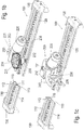
- Fig. 1a shows an electromotive furniture drive in a perspective view.
- the furniture drive is designed as a linear drive with a straight guide path 100 here, along which an output unit 200 can be moved.
- the guideway 100 is essentially formed by a guiding profile 110 which has an approximately rectangular cross section.
- FIG. 1 a shows the electric motor drive Fig. 1 a shown with cut guide profile 110.
- elements of the output unit 200 have been removed ( Fig. 1b ) or cut ( Fig. 1c ) to clarify the internal structure of the output unit 200.
- Fig. 2 shows the underside of the electromotive furniture drive in a perspective view.
- the guide profile 110 is preferably an aluminum profile; it can also be designed as a plastic profile for certain applications in which the drive does not apply excessive displacement forces or the drive does not require excessive bending forces. From the sectional view of the guide profile 110 it can be seen that the profile has a groove 111 for receiving a rack 120.
- the groove 111 for receiving a toothed rack 120 is C-shaped, the toothed rack 120 on its side opposite the toothing having a corresponding complementary one Has profile, so that the rack 120 can be inserted into the groove 111.
- the rack 120 can be made with a corresponding profile, for example from a hard, resistant plastic.
- the rack 120 can be an extruded profile with milled teeth or else an element produced as a whole by injection molding.
- the rack 120 can be formed in one or more parts. Particularly in the case of a furniture drive with long travel paths, the production of a correspondingly long, one-piece extruded profile can be problematic. In such a case, a multi-part rack 120 is appropriate.
- a guide groove 112 is also formed on the side of the guide profile 110 shown in the figure above. Adjacent to the groove 111 for receiving the rack 120, a raceway 113 is provided for a counter bearing. On the side opposite the rack 120, the raceway 113 is closed with a contact edge 114 arranged parallel to the groove 111.
- the function of the counter bearing is explained below in connection with the more detailed description of the output unit 200.
- stiffening ribs 115 are formed within the guide profile 110.
- fastening flanges 130 provide fastening means 131, here in the form of threaded bores.
- the guideway 100 and thus the electromotive drive on the furniture, for example on the furniture fitting, can be fixed via the fastening means 131.
- the fastening flanges 130 are connected to the guide profile 110 via screws 132 or other fastening means.
- the screws 132 can be self-tapping screws, for example, which are screwed or screwed into suitable chambers or onto suitable webs or walls of the guide profile 110. Such suitable chambers or webs are defined, for example, by the stiffening ribs 115.
- Switch cams 133 are also arranged on the fastening flanges 130 and interact with limit switches which are not visible in this figure and are explained below.
- the rack 120 inserted into the guide profile 110 is also fixed by the fastening flanges 130.
- the output unit 200 has a slide 210 as the housing part and base element, which is formed, for example, as an injection molded plastic part in one piece as an approximately C-shaped block, which at least partially encompasses the guide profile 110 and in this sense runs along the outside of the guide profile 110.
- this has sections 213 which partially extend over the underside of the guide profile 210 and thus prevent the output unit 200 from being removed from the guide track 100 upwards.
- the guide groove 112 can be designed as a dovetail groove or as a groove with a T-shaped or with an L-shaped cross section. According to this alternative or additional embodiment of at least a partial area of the guideway 100, the guideway 100 thus has a guiding profile 110 into which the slide 210 engages at least partially.
- the slider 210 can be made in several parts, wherein it consists of at least two sections and at least one section is designed as a guide section for guiding on the guide profile 110, as a fastening section for fastening via a fastening means 211, 212, as a receiving section for the gear is formed, or is designed as a bearing section for gear components such as worm 221, such as drive shaft 230, such as worm gear 231, such as output gear 232.
- the shape of the slide 210 on its surface facing the guide profile 110 is adapted accordingly, so that the slide 210 is displaceably mounted along the guide profile 110 so that it is as free of play as possible or with little play and with respect to all axes.
- Fastening means 211 for direct or indirect connection to a piece of furniture, for example a furniture fitting, are provided on at least one, preferably two opposite sides of the slide 210.
- three bores are provided as fastening means 211, of which at least one, for example the larger central bore, is provided with a thread.
- two parallel edges projecting from the bores are provided as further fastening means 212.
- a plate provided with a central bore and two pegs can be inserted between the further fastening means 211, the two pegs being inserted into the outer bores and the fastening means 211 and one in the central threaded bore of the fastening means 211 Screw is inserted.
- the edges as further fastening means 212 prevent the inserted plate from twisting in addition to the inserted pin.
- a drive motor 220 is fixed to the slide 210 for moving the slide 210.
- a worm 221 is placed on an output shaft of the motor 220.
- a drive shaft 230 is provided with a worm gear 231 which is in engagement with the worm 221 and which is connected in a rotationally fixed manner to an output gear 232 which is in engagement with the rack 120.
- the drive shaft 230 is at least partially hollow, so that at least in the area of the worm gear 231, but preferably also deeper into the drive shaft, a bearing receptacle 234 is formed, with the aid of which the drive shaft 230 can be supported at least at its upper end in the figure.
- the worm gear 231 and the drive gear 232 can be formed in one piece, or they can also be separate components, which then preferably interlock with one another.
- the drive shaft 230 is hollow over its entire length and can be rotated to one over its entire length Bearing mandrel attached.
- the bearing mandrel is fixed to a gear housing 240 which is screwed onto the slide 210 (cf. Fig. 1a , 1c ).
- the bearing mandrel can be integrally formed with the gear housing 240 on this upper side.
- the slide 210 and the gear housing 240 together also form a housing of the output unit. Likewise, they can be viewed together as a multi-part gear housing.
- the bearing mandrel protrudes from the drive shaft 230.
- the bearing mandrel has a bearing pin 235 at this lower end, which, for example, in Fig. 1c is visible.
- This journal 235 is mounted in a counter bearing 236, which runs in the previously described track 213.
- the drive shaft 230 not to be hollow over its entire length and for the bearing pin not to protrude from the drive shaft 230 at the lower end.
- the bearing journal can be formed on the drive shaft 230 and the drive shaft 230 can be mounted on this side directly in the counter bearing 236.
- the motor 220 When the motor 220 is operating, its rotational movement is reduced by the worm 221 and the worm gear 231 and, if necessary, is transmitted to the drive shaft 230 in a self-locking manner.
- the interaction of the drive gear 232 and the rack 120 translates the rotary movement of the drive shaft 230 into a linear movement of the slide 210 along the guide profile 110
- the counter bearing 236 is provided to be able to absorb (toothing forces) which would push the toothing apart.
- large forces occurring between the output gear 232 and the rack 120 are supported by the counter bearing 236 on the contact edge 114 of the guide profile 110.
- the counter bearing 236 is designed as a radial ball bearing.
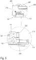
- Fig. 3 In the upper area, a section through the electromotive drive, which is carried out perpendicular to the longitudinal direction of the guideway 100, is shown. In the enlargement of the detail in the lower area of the figure, the counter bearing, which is supported on the contact edge 114 of the raceway 112, can again be clearly seen. This illustration also shows how the thread of the screw 132 of the fastening flange 130 cuts into the chamber formed by the stiffening ribs 115 of the guide profile 110.
- Fig. 4a shows a further perspective and sectional view of the electric motor drive of the Fig. 1 .
- the slider 210 is shown in section.
- An electrical connection 250 via which the electromotive drive is supplied with current, is arranged under the upper side of the transmission housing 240.
- This electrical connection is also in the Figures 1a to 1c to recognize. It can be designed as a fixed cable connection or as a plug connection.
- limit switches 251 are arranged on the slide 210.
- Limit switches 251 may be mechanical switches, such as microswitches in the illustrated embodiment.
- optical switches for example fork or reflex light barriers, in conjunction with corresponding control electronics.
- the limit switches 251 are arranged in such a way that they are actuated by the respective switching cams 133 which are arranged on the fastening flange 130 at the end of the guide profile 110 when the output unit 200 travels in the end region of the guide region 110.
- the limit switches 251 are thus electrically connected to the electrical connection 251 and the drive motor 220, so that a further travel of the output unit 200 in the direction of an actuated limit switch 251 is prevented.
- the limit switches are preferably 251 introduced into the supply circuit of the drive motor 220 and open the supply circuit when switching is carried out at the respective end region of the guide profile 110 or the guide track 100.
- Fig. 4b shows the limit switches 251 and the switching cams 133 which interact with them once again in an enlarged detail view.
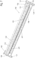
- FIG. 7 also shows a perspective view of the guide profile used in this exemplary embodiment.
- the same reference numerals in these figures denote the same or equivalent elements as in the preceding figures.
- Concerning. of the basic structure of this electromotive furniture drive in the second exemplary embodiment reference is made to the explanation of the first exemplary embodiment.
- the guide profile 110 is formed in one piece with the rack 120 in this exemplary embodiment.
- the fastening flange 130 is made in one piece with the guide profile 110.
- the toothed rack 120 can be designed such that it itself represents the guide profile 110.
- the guideway 100 is made of plastic in an injection molding process.
- Rib structures are arranged in the lower area to increase stability. These are designed as longitudinal ribs 116.
- Another difference relates to the raceway 113 for the counter bearing 236.
- This raceway is provided with dust openings 117, through which dust which falls, for example, from furniture upholstery onto the electromotive drive arranged in the interior of the furniture, accumulates in the raceway 113. Penetration of dust into the drive area within the slider 210 is thus prevented or at least reduced, thereby the risk of blocking or increased wear of the drive elements is reduced.
- a covering of the toothed rack 120 can be provided to prevent foreign bodies or dust from falling in and entering.
- a gear stage is formed by the worm 221 and the worm wheel 231 between the drive motor 220 and the driven gear 232 in order to reduce the speed.
- gears are possible, for example a planetary gear, a spur gear or a friction gear or as a planetary gear.
- a multi-stage gear can also be used instead of a one-stage gear.
- a helical toothing can also be used instead of a straight toothing between the output gear and the rack.
- Gearing in the manner of a developed worm wheel is also conceivable.
- a toothed rack and toothing means any contouring between an element (“toothed rack”) extending along the guideway 110 and a rotating driven element (“driven gear”). The contouring can be done on a microscopic scale, so that a friction wheel drive is also conceivable.
- the guideway 100 is straight. However, it is also conceivable for the guideway 100 to be at least partially curved.
- the guideway 100 can follow the movement of a force introduction point of a furniture component or a moving part of the furniture fitting, which is connected to the electric motor drive. It is also possible that the guideway 100 is part of the furniture fitting itself.
- the guideway 100 can be a straight or curved slide of a furniture fitting provided with teeth on at least one side.
- slide 210 and rack 120 are guided relative to one another.
- the description of this arrangement can be explained in a reduced manner, with the The toothing of the rack 120, which is in operative connection, is guided to the output gear 232 which forms the gear output and the guide or the guide profile 110 absorbs at least the toothing forces of the toothed rack, so that the toothed rack remains in engagement.
- alternative rack profiles are designed in the manner of a rack toothing.
- alternative toothings of the output gear 232 are designed in the manner of a chain wheel or in the manner of a rack wheel. It is essential, however, that a linear gear acting as a rack and pinion gear is formed.
- the bearings of the individual gear wheels are shown in the descriptions above.
- the special structure of the gear housing 240 and slide 210 permits particularly simple mounting and mounting of the gear members and the counter bearing 236 and is not restricted to the embodiments shown.
- the bearing of the worm 221, the drive shaft 230, the worm gear 231, the driven gear 232 can be arranged partially or completely in the gear housing 240 or at least partially or completely in the slide 210.
- worm 221, drive shaft 230, worm gears 231, output gear 232 can be partially or completely received by the gear housing 240 and / or partially or completely by the slide 210.
- the aforementioned bearings and guides are designed as plain bearings and as sliding guides. Alternatively, however, at least some of the bearings and guides have rolling bearings, for example in the form of deep groove ball bearings.
- the drive motor 220 is switched off by the limit switch 251, which is designed, for example, as a microswitch.
- a reversible switch which is also arranged in the motor circuit and is formed by a motor current threshold switch, for example a poly switch component.
- mechanical end stops are arranged, which are formed, for example, as follows: end of the toothing of the rack toothing; Protruding a toothed portion of the rack 120; through the mounting flange 130, which protrudes beyond the limits of the guideway 100 jumps; Fastening screws of the furniture drive in the area of the fastening flange 130. Electrical end stops can also be combined with mechanical end stops.
- the guide profile 110 here has no separate raceway for the counter bearing at the lower end of the drive shaft, which is not visible here. Rather, the drive shaft is supported at both ends in the gear housing 210. This means that larger gearing forces act through the engagement of the driven gear (cf. 232 of Fig. 1b ) in the rack 120, these forces are absorbed by the gear housing 210 and on the opposite side of the rack 120 by the guide profile 110. Especially in Fig. 10 it can be clearly seen how the gear housing 210 grips around the guide profile 110 like a clamp for this purpose.
- plain or ball bearings can be used as bearings for the drive shaft.
- ball bearings are advantageous in order to keep friction losses as low as possible and to be able to use smaller drive motors 220.
- the gear housing 240 does not cover the entire slide 210, but only the part in which the mechanical Drive elements are located.
- a separate connection cover 252 is provided for the area of the electrical connections 250.
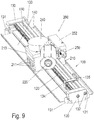
- FIG. 8 Switch cams for limit switch actuation arranged on the right side. This is not mounted on the mounting flange here, but as an adjustable switching cam 135 on a slide 134 that can be displaced along the guide profile 110. In this way, the end position of the slide 210 can be adapted to the respective furniture.
- the tab 134 can be provided with a fixing means, for example a (maggot) screw, in order to fix it in its desired position.
- the tab 134 is designed with a clamping device or further as a clamp to connect the switch cam 135 to the guide profile 110.
- At least one further tab 134 can be provided, so that a number of tabs 134 with switching cams 135 are provided on the guide profile 110.
- the switching cams 135, which are arranged the most distant from one another, are provided for the end position switch-off.
- Each switching cam 135, which is arranged between the switching cams 135 provided for the end position switch-off, is provided for an intermediate stop or for an intermediate position.
- the switching cam 133, 135 can actuate a switch or move a transmitter which actuates a switch.
- the drive unit 200 has at least one switch, the switch contact of which is integrated in the circuit of the drive motor 220 or alternatively gives a switch signal to a higher-level control when actuated.
- a carpet protection rail 140 is arranged below the guide rail 110, which prevents threads of a long-pile carpet from getting between the drive gear and the rack 110. Also, traces of grinding of the slider 210 with a furniture drive arranged very low in the furniture and in a dripping of grease or the like. prevented from the furniture drive.
- the carpet protection rail 140 is preferably clamped or plugged onto the furniture drive and can therefore be easily retrofitted. Alternatively, the carpet protection rail 140 is included connected to the electromotive furniture drive when it is in the installed position in the furniture.
- Both the tab 134 with the more adjustable switching cam 135 and the carpet protection rail 140 can also be used in the exemplary embodiments shown above.
Description
Die Erfindung betrifft einen elektromotorischen Möbelantrieb mit einer Führungsbahn und einer sich entlang der Führungsbahn bewegenden und diese zumindest teilweise umgreifenden Abtriebseinheit, wobei die Führungsbahn ein Führungsprofil und eine Zahnstange aufweist, und wobei die Abtriebseinheit einen Antriebsmotor mit einem Drehzahlreduziergetriebe und einem Abtriebszahnrad aufweist, das sich im Eingriff mit der Zahnstange der Führungsbahn befindet.The invention relates to an electromotive furniture drive with a guideway and an output unit moving along the guideway and at least partially encompassing it, wherein the guideway has a guide profile and a toothed rack, and wherein the output unit has a drive motor with a speed reduction gear and an output gearwheel which is located in the Engagement with the rack of the guideway.
Elektromotorische Möbelantriebe, im Folgenden abgekürzt auch als "Antriebe" bezeichnet, werden beispielsweise in Liege- und Sitzmöbeln eingebaut, um eine Verstellung von Möbelteilen wie Sitzen, Rückenlehnen, Fußbänken usw. relativ zu einem Grundkörper des Möbels und relativ zueinander komfortabel bewegen zu können.Electromotive furniture drives, hereinafter also abbreviated as "drives", are installed, for example, in reclining and seating furniture in order to be able to comfortably move an adjustment of furniture parts such as seats, backrests, footstools, etc. relative to a base body of the furniture and relative to one another.
Verstellbare Sitzmöbel insbesondere sog. Fernseh- oder Entspannungssessel, weisen dazu üblicherweise einen mechanisch relativ aufwändigen Möbelbeschlag auf, der im Zusammenwirken einer Vielzahl von Hebeln und Gestängen einen komplexen Bewegungsablauf der verschiedenen an ihm montierten Polstereinheiten der Möbel ermöglicht.Adjustable seating furniture, in particular so-called television or relaxation armchairs, usually has a mechanically relatively complex furniture fitting which, in cooperation with a plurality of levers and rods, enables a complex movement sequence of the various upholstery units of the furniture mounted on it.
In der Druckschrift
Zur Motorisierung von höhenverstellbaren Möbeln, insbesondere Tischen ist aus der Druckschrift
Aus den Druckschriften
Es ist daher eine Aufgabe der vorliegenden Erfindung, einen elektromotorischen Antrieb der eingangs genannten Art zu schaffen, der ein auf einfache Weise in seiner Länge anpassbare Grundeinheit aufweist und eine möglichst gut zugänglich entlang der Grundeinheit verfahrbare Abtriebseinheit aufweist. Diese Aufgabe wird gelöst durch einen elektromotorischen Möbelantrieb mit den Merkmalen des unabhängigen Anspruchs. Vorteilhafte Ausgestaltungen und Weiterbildungen sind in den abhängigen Ansprüchen angegeben.It is therefore an object of the present invention to provide an electric motor drive of the type mentioned at the outset which has a basic unit which can be easily adjusted in length and has an output unit which can be moved as easily as possible along the basic unit. This object is achieved by an electromotive furniture drive with the features of the independent claim. Advantageous refinements and developments are specified in the dependent claims.
Ein erfindungsgemäßer elektromotorischer Möbelantrieb der eingangs genannten Art zeichnet sich dadurch aus, dass die Zahnstange einstückig mit dem Führungsprofil ausgebildet ist. Auf diese Weise wird ein Möbelantrieb geschaffen, der eine einfach und kostengünstig herstellbare Führungsbahn aufweist, die bei gleichem Aufbau der Abtriebseinheit leicht in unterschiedlichen Längen und damit Verschiebewegen ausgebildet sein kann. Dadurch, dass die Führungsbahn und die Zahnstange integral miteinander ausgebildet sind, ist ein kompakter Aufbau und eine gute Führung gewährleistet. Die Abtriebseinheit liegt außerhalb der Führungsbahn und ist daher in ihrem Aufbau und ihrer Größe nicht durch die Ausgestaltung der Führungsbahn eingeschränkt.An electromotive furniture drive according to the invention of the type mentioned at the outset is characterized in that the rack is formed in one piece with the guide profile. In this way, a furniture drive is created which has a guide track which can be produced simply and inexpensively and which, with the same construction of the output unit, can easily be formed in different lengths and thus displacement paths. The fact that the guideway and the rack are integrally formed with one another ensures a compact structure and good guidance. The output unit lies outside the guideway and is therefore not limited in its structure and size by the design of the guideway.
Bevorzugt ist die Zahnstange nicht nur integral mit dem Führungsprofil ausgebildet, sondern bildet das Führungsprofil. Erfindungsgemäß sind am Führungsprofil zu beiden Enden Befestigungsflansche als Befestigungsmittel angeordnet, bevorzugt einstückig mit dem Führungsprofil. Zur Erhöhung der Stabilität ist das Führungsprofil mit einer Rippenstruktur versehen. Erfindungsgemäß ist das Führungsprofil in einem Spritzgussprozess aus Kunststoff hergestellt. Die Rippenstruktur zur Stabilisierung ist bevorzugt so ausgebildet, dass sie in einem Spritzgussprozess herstellbar ist. Weiter bevorzugt ist eine Abdeckung der Zahnstange vorgesehen
In einer vorteilhaften Ausgestaltung des Möbelantriebs ist benachbart zur Zahnstange eine Laufbahn für ein Gegenlager ausgebildet, das das Abtriebszahnrad direkt oder indirekt lagert. Auf diese Weise können Verzahnungskräfte, die zwischen der Zahnstange und dem Antriebszahnrad wirken, unmittelbar in das Führungsprofil eingeleitet werden. Dazu kann die Zahnstange entlang einer Seite der Laufbahn verlaufen und eine Anlagekante für das Gegenlager kann an einer der Zahnstange gegenüberliegenden Seite der Laufbahn ausgebildet sein.The rack is preferably not only formed integrally with the guide profile, but rather forms the guide profile. According to the invention, fastening flanges are arranged as fastening means on the guide profile at both ends, preferably in one piece with the guide profile. To increase stability, the guide profile is provided with a rib structure. According to the invention, the guide profile is made of plastic in an injection molding process. The rib structure for stabilization is preferably designed such that it can be produced in an injection molding process. A cover of the toothed rack is also preferably provided
In an advantageous embodiment of the furniture drive, a track for a counter bearing is formed adjacent to the rack and supports the driven gear directly or indirectly. In this way, toothing forces that act between the rack and the drive gear can be introduced directly into the guide profile. For this purpose, the rack can run along one side of the track and a contact edge for the counter bearing can be formed on a side of the track opposite the rack.
In einer weiteren vorteilhaften Ausgestaltung des Möbelantriebs ist ein Lagerdorn, durch den das Abtriebszahnrad gelagert ist, an einem Gehäuse der Abtriebseinheit festgelegt. Der Lagerdorn kann dabei an einem Ende einstückig mit dem Gehäuse ausgebildet sein und am anderen Ende mit dem Gegenlager zusammenwirken, wodurch ein kompakter Aufbau der Abtriebseinheit mit wenigen Einzelelementen ermöglicht wird.In a further advantageous embodiment of the furniture drive, a bearing mandrel, through which the driven gear is mounted, is fixed to a housing of the driven unit. The bearing mandrel can be integrally formed with the housing at one end and with the counter bearing at the other end interact, which enables a compact structure of the output unit with a few individual elements.
Wenn eine Gegenlagerung des Antriebszahnrads in der der Zahnstange benachbarten Laufbahn nicht erfolgt, kann alternativ der Lagerdorn an beiden Ende in dem Gehäuse der Abtriebseinheit festgelegt sein.If there is no counter bearing of the drive gear in the raceway adjacent to the rack, the bearing mandrel can alternatively be fixed at both ends in the housing of the output unit.
Erfindungsgemäß weist die Abtriebseinheit an mindestens einer, bevorzugt zwei gegenüberliegenden Seiten, Befestigungsmittel zur Befestigung mit einem Möbelteil oder einem Teil eines Möbelbeschlags auf.According to the invention, the output unit has at least one, preferably two opposite sides, fastening means for fastening with a furniture part or part of a furniture fitting.
Als Drehzahlreduziergetriebe kann vorteilhaft ein Schneckengetriebe mit einer mit dem Antriebsmotor verbundenen Schnecke und einem mit dem Abtriebszahnrad verbundenen Schneckenrad vorgesehen sein. So wird eine hohe Untersetzung bei einfachem Aufbau und gleichzeitiger Selbsthemmung erzielt.A worm gear with a worm connected to the drive motor and a worm wheel connected to the driven gear can advantageously be provided as the speed reduction gear. In this way, a high reduction ratio is achieved with a simple structure and simultaneous self-locking.
Vorteilhaft kann das Abtriebszahnrad nach Art eines Triebstockrades ausgebildet sein.The output gear can advantageously be designed in the manner of a rack wheel.
In einer weiteren vorteilhaften Ausgestaltung des Möbelantriebs weist die Abtriebseinheit einen Schieber auf, der das Führungsprofil zumindest teilweise umgreift. Dabei sind der Schieber und die Zahnstange relativ zueinander geführt, wobei die Führung zumindest Verzahnungskräfte der Zahnstangenverzahnung aufnimmt. Dabei kann vorteilhaft das Abtriebszahnrad teilweise oder vollständig im Schieber oder in einem auf den Schieber aufgesetzten Getriebegehäuse angeordnet sein. Falls als Drehzahlreduziergetriebe ein Schneckengetriebe mit Schnecke und Schneckenzahnrad vorgesehen ist, können auch diese Komponenten teilweise oder vollständig im Schieber oder in dem auf den Schieber aufgesetzten Getriebegehäuse angeordnet sind.In a further advantageous embodiment of the furniture drive, the output unit has a slide which at least partially encompasses the guide profile. The slide and the toothed rack are guided relative to one another, the guide absorbing at least toothing forces of the toothed rack toothing. In this case, the driven gear wheel can advantageously be arranged partially or completely in the slide or in a gear housing placed on the slide. If a worm gear with worm and worm gear is provided as the speed reduction gear, these components can also be arranged partially or completely in the slide or in the gear housing placed on the slide.
In einer weiteren vorteilhaften Ausgestaltung des Möbelantriebs sind Endschalter oder Endanschläge vorgesehen, um eine Bewegung der Abtriebseinheit über die Enden der Führungsbahn hinaus zu verhindern. Zur Betätigung der Endschalter sind bevorzugt Schaltnocken an der Führungsbahn angeordnet. Dabei kann zumindest einer der Schaltnocken an einem entlang der Führungsbahn verschiebbaren Reiter angeordnet sein, wodurch sich die Endposition der Abtriebseinheit variabel einstellen lässt.In a further advantageous embodiment of the furniture drive, limit switches or end stops are provided in order to move the output unit to prevent beyond the ends of the guideway. Switch cams are preferably arranged on the guideway to actuate the limit switches. In this case, at least one of the switching cams can be arranged on a slide that can be displaced along the guideway, as a result of which the end position of the output unit can be variably adjusted.
Schließlich kann ein an den Möbelantrieb ansteckbares Teppichschutzschild vorgesehen sein, das den Möbelantrieb zumindest im Bereich eines Verschiebewegs der Abtriebseinheit nach unten hin abschirmt. Das Teppichschutzschild verhindert, dass Fäden eines langflorigen Teppichs in den Antriebsmechanismus gelangen können. Auch werden Schleifspuren der Abtriebseinheit bei einem sehr niedrig im Möbel angeordneten Möbelantrieb sowie in ein Abtropfen von Fett o.ä. aus dem Möbelantrieb verhindert.Finally, a carpet protective shield that can be plugged onto the furniture drive can be provided, which shields the furniture drive downwards at least in the region of a displacement path of the output unit. The carpet protection shield prevents threads of a long-pile carpet from getting into the drive mechanism. Also, traces of grinding of the output unit with a furniture drive arranged very low in the furniture as well as in a dripping of grease or the like. prevented from the furniture drive.
Die Erfindung wird nachfolgend anhand von Ausführungsbeispielen mithilfe von Figuren näher erläutert. Es zeigen:
- Fig. 1 a bis 1c
- jeweils perspektivische Ansichten eines ersten nicht erfindungsgemäßen elektromotorischen Möbelantriebs in schematischen, teilweise geschnittenen Darstellungen;
- Fig. 2
- eine weitere perspektivische Darstellung des elektromotorischen Möbelantriebs des ersten nicht erfindungsgemäßen Ausführungsbeispiels;
- Fig. 3
- eine weitere Schnitt- und Detaildarstellung des elektronischen Möbelantriebs des ersten nicht erfindungsgemäßen Ausführungsbeispiels;
- Fig. 4a und 4b
- weitere perspektivische Schnitt- und Detaildarstellungen des elektromotorischen Möbelantriebs des ersten nicht erfindungsgemäßen Ausführungsbeispiels;
- Fig. 5a und 5b
- perspektivische Darstellungen eines elektromotorischen Möbelantriebs in einem zweiten Ausführungsbeispiel;
- Fig. 6a bis 6c
- verschiedene perspektivische und teilweise geschnittene Darstellungen des elektromotorischen Möbelantriebs im zweiten Ausführungsbeispiel;
- Fig. 7
- eine perspektivische Darstellung der Führungsbahn des elektromotorischen Möbelantriebs im zweiten Ausführungsbeispiel und
- Fig. 8 bis 10
- verschiedene perspektivische Darstellungen eines elektromotorischen Möbelantriebs in einem dritten Ausführungsbeispiel.
- 1 a to 1c
- perspective views of a first electromotive furniture drive not according to the invention in schematic, partially sectioned representations;
- Fig. 2
- a further perspective view of the electromotive furniture drive of the first embodiment not according to the invention;
- Fig. 3
- a further sectional and detailed representation of the electronic furniture drive of the first embodiment not according to the invention;
- 4a and 4b
- further perspective sectional and detailed representations of the electromotive furniture drive of the first embodiment not according to the invention;
- 5a and 5b
- perspective views of an electromotive furniture drive in a second embodiment;
- 6a to 6c
- different perspective and partially sectioned representations of the electromotive furniture drive in the second embodiment;
- Fig. 7
- a perspective view of the guide track of the electromotive furniture drive in the second embodiment and
- 8 to 10
- different perspective views of an electromotive furniture drive in a third embodiment.
Die Führungsbahn 100 ist in dieser Ausgestaltung im Wesentlichen durch ein Führungsprofil 110 gebildet, das einen in etwa rechteckigen Querschnitt aufweist.In this embodiment, the
In den
Das Führungsprofil 110 ist bevorzugt ein Aluminiumprofil, es kann für bestimmte Anwendungen, in denen keine zu großen Verschiebekräfte von dem Antrieb aufgebracht oder keine zu großen Biegekräfte von dem Antrieb aufgenommen werden müssen, auch als Kunststoffprofil ausgebildet sein. Aus der Schnittdarstellung des Führungsprofils 110 ist ersichtlich, dass das Profil eine Nut 111 zur Aufnahme einer Zahnstange 120 aufweist. Die Nut 111 zur Aufnahme einer Zahnstange 120 ist C-förmig ausgeführt, wobei die Zahnstange 120 an ihrer der Zahnung entgegen gesetzten Seite ein entsprechendes komplementäres Profil aufweist, sodass die Zahnstange 120 in die Nut 111 eingeschoben werden kann. Die Zahnstange 120 kann mit einem entsprechenden Profil beispielsweise aus einem harten, widerstandsfähigen Kunststoff hergestellt sein. Es kann sich bei der Zahnstange 120 um ein extrudiertes Profil mit eingefräster Zahnung oder auch um ein als Ganzes im Spritzgussverfahren hergestelltes Element halten. Die Zahnstange 120 kann ein- oder auch mehrteilig ausgebildet sein. Insbesondere bei einem Möbelantrieb mit langen Verfahrwegen kann die Herstellung eines entsprechend langen einteiligen extrudierten Profils problematisch sein. In einem solchen Fall bietet sich eine mehrteilige Zahnstange 120 an.The
Auf der in der Figur oben dargestellten Seite des Führungsprofils 110 ist zudem eine Führungsnut 112 ausgebildet. Angrenzend an die Nut 111 zur Aufnahme der Zahnstange 120 ist eine Laufbahn 113 für ein Gegenlager vorgesehen. Auf der der Zahnstange 120 gegenüber liegenden Seite ist die Laufbahn 113 mit einer parallel zur Nut 111 angeordneten Anlagekante 114 abgeschlossen. Die Funktion des Gegenlagers wird nachfolgend im Zusammenhang mit der detaillierteren Beschreibung der Abtriebseinheit 200 erläutert. Zusätzlich können, wie aus den
Zu beiden Enden des Führungsprofils 110 ist dieses mit Befestigungsflanschen 130 abgedeckt. Die Befestigungsflansche 130 stellen Befestigungsmittel 131, hier in Form von Gewindebohrungen bereit. Über die Befestigungsmittel 131 kann die Führungsbahn 100 und damit der elektromotorische Antrieb am Möbel, beispielsweise am Möbelbeschlag, festgelegt werden. Die Befestigungsflansche 130 sind über Schrauben 132 oder anderen Befestigungsmittel mit dem Führungsprofil 110 verbunden. Die Schrauben 132 können beispielsweise selbstschneidende Schrauben sein, die in geeignete Kammern oder an geeignete Stege bzw. Wandungen des Führungsprofils 110 eingeschraubt bzw. angeschraubt werden. Derartige geeignete Kammern bzw. Stege sind beispielsweise durch die Versteifungsrippen 115 definiert. An den Befestigungsflanschen 130 sind zudem Schaltnocken 133 angeordnet, die mit in dieser Figur nicht sichtbaren und nachfolgend erläuterten Endschaltern zusammen wirken. Durch die Befestigungsflansche 130 ist auch die in das Führungsprofil 110 eingeschobene Zahnstange 120 festgelegt.At both ends of the
Die Abtriebseinheit 200 weist als Gehäuseteil und Grundelement einen Schieber 210 auf, der beispielsweise als Spritzgusskunststoffteil einstückig als ein in etwa C-förmiger Block ausgebildet ist, der das Führungsprofil 110 zumindest teilweise umgreift und in diesem Sinne an der Außenseite des Führungsprofils 110 entlang läuft. An der Unterseite des Schiebers 210 weist dieser Abschnitte 213 auf, die teilweise über die Unterseite des Führungsprofils 210 greifen und so verhindern, dass die Abtriebseinheit 200 nach oben von der Führungsbahn 100 abgenommen werden kann. Alternativ oder zusätzlich kann zu diesem Zweck auch z.B. die Führungsnut 112 als Schwalbenschwanz-Nut oder als Nut mit einem T-förmigen oder mit einem L-förmigen Querschnitt ausgeführt sein. Gemäß dieser alternativen oder zusätzlichen Ausführungsform zumindest eines Teilbereiches der Führungsbahn 100 weist diese somit ein Führungsprofil 110 auf, in das der Schieber 210 zumindest teilweise hineingreift.The
In einer alternativen Ausbildung kann der Schieber 210 mehrteilig ausgeführt sein, wobei er aus wenigstens zwei Abschnitten besteht und zumindest ein Abschnitt als Führungsabschnitt zur Führung an dem Führungsprofil 110 ausgebildet ist, als Befestigungsabschnitt zur Befestigung über ein Befestigungsmittel 211, 212 ausgebildet ist, als Aufnahmeabschnitt für das Getriebe ausgebildet ist, oder als Lagerungsabschnitt für Getriebebauteile wie Schnecke 221, wie Antriebswelle 230, wie Schneckenzahnrad 231, wie Abtriebszahnrad 232 ausgebildet ist.In an alternative embodiment, the
Die Formgebung des Schiebers 210 an seinen dem Führungsprofil 110 zugewandten Fläche ist diesem entsprechend angepasst, sodass der Schieber 210 möglichst spielfrei bzw. mit einem geringen Spiel und bzgl. aller Achsen verdrehsicher entlang dem Führungsprofil 110 verschiebbar gelagert ist. An zumindest einer, bevorzugt zwei gegenüberliegenden Seiten des Schiebers 210, sind Befestigungsmittel 211 zur direkten oder indirekten Verbindung mit einem Möbelteil, beispielsweise einem Möbelbeschlag, vorhanden.The shape of the
Vorliegend sind als Befestigungsmittel 211 drei Bohrungen vorgesehen, von denen mindestens eine, beispielsweise die größere zentrale Bohrung mit einem Gewinde versehen ist. Zudem sind zwei parallele und gegenüber den Bohrungen vorstehende Kanten als weitere Befestigungsmittel 212 vorgesehen. Zur Verbindung mit dem Möbel oder Möbelbeschlag kann beispielsweise eine mit einer zentralen Bohrung und zwei Zapfen versehenen Platte zwischen die weiteren Befestigungsmittel 211 eingesetzt werden, wobei die beiden Zapfen in die äußeren Bohrungen und der Befestigungsmittel 211 eingesteckt sind und in die mittlere Gewindebohrung der Befestigungsmittel 211 eine Schraube eingesetzt wird. Die Kanten als weitere Befestigungsmittel 212 verhindern zusätzlich zu dem eingesteckten Zapfen eine Verdrehung der eingesetzten Platte. Denkbar wäre auch z.B. ein Gelenk, welches mit dem Befestigungsmittel 211 an den Schieber 210 befestigt ist, oder ein Befestigungsmittel 211, welches ein Gelenk aufweist oder bildet. Selbstverständlich sind andere Befestigungsmittel als die hier dargestellten zur Verbindung des Schiebers 210 mit dem Möbel oder Möbelbeschlag möglich.In the present case, three bores are provided as fastening means 211, of which at least one, for example the larger central bore, is provided with a thread. In addition, two parallel edges projecting from the bores are provided as further fastening means 212. For connection to the furniture or furniture fitting, for example, a plate provided with a central bore and two pegs can be inserted between the further fastening means 211, the two pegs being inserted into the outer bores and the fastening means 211 and one in the central threaded bore of the fastening means 211 Screw is inserted. The edges as further fastening means 212 prevent the inserted plate from twisting in addition to the inserted pin. It would also be conceivable, for example a joint which is fastened to the
Zur Bewegung des Schiebers 210 ist ein Antriebsmotor 220 an dem Schieber 210 festgelegt. In der
Im hier gezeigten Ausführungsbeispiel ist die Antriebswelle 230 über ihre gesamte Länge hohl ausgebildet und ist über ihre gesamte Länge drehbar auf einen Lagerdorn aufgesetzt. Der Lagerdorn ist an einem Getriebegehäuse 240 festgelegt, das auf den Schieber 210 aufgeschraubt ist (vgl.
Der Schieber 210 und das Getriebegehäuse 240 bilden zusammen auch ein Gehäuse der Abtriebseinheit. Ebenso können sie gemeinsam als mehrteiliges Getriebegehäuse angesehen werden.The
Am gegenüberliegenden unteren Ende, also benachbart zum Abtriebszahnrad 232, ragt der Lagerdorn aus der Antriebswelle 230 heraus. Der Lagerdorn weist an diesem unteren Ende einen Lagerzapfen 235 auf, der beispielsweise in
Bei Betrieb des Motors 220 wird dessen Drehbewegung über die Schnecke 221 und das Schneckenzahnrad 231 untersetzt und ggf. selbsthemmend auf die Antriebswelle 230 übertragen. Das Zusammenspiel von dem Antriebszahnrad 232 und der Zahnstange 120 überträgt die Drehbewegung der Antriebswelle 230 in eine Linearbewegung des Schiebers 210 entlang des Führungsprofils 110. Um beim Eingriff der Schnecke 221 in das Schneckenzahnrad 231 und insbesondere beim Eingriff des Abtriebszahnrads 232 in die Zahnstange 120 auftretenden Kräfte (Verzahnungskräfte), die die Zahnung auseinander drücken würden, aufnehmen zu können, ist das Gegenlager 236 vorgesehen. Insbesondere große zwischen Abtriebszahnrad 232 und Zahnstange 120 auftretende Kräfte werden von dem Gegenlager 236 an der Anlagekante 114 des Führungsprofils 110 abgestützt. Vorliegend ist das Gegenlager 236 als ein Radialkugellager ausgebildet. Anstelle des dargestellten Radialkugellagers als Gegenlager 236 kann dieses auch eine Rolle oder ein in der Laufbahn 113 verschiebbarer Lagerklotz eingesetzt werden. Es ist auch denkbar, das Gegenlager 236 nicht unmittelbar in der Laufbahn 113 zu führen, sondern in dem Schieber 210 abzustützen, welcher sich wiederum an dem Führungsprofil 110 und/oder an der Zahnstange 120 abstützt.When the
In
Weiter sind am Schieber 210 zwei Endschalter 251 angeordnet. Die Endschalter 251 können mechanische Schalter sein, wie beispielsweise Mikroschalter in dem dargestellten Ausführungsbeispiel. Alternativ ist es auch möglich, optische Schalter, beispielsweise Gabel- oder Reflexlichtschranken im Zusammenhang mit einer entsprechenden Steuerelektronik zu verwenden. Die Endschalter 251 sind so angeordnet, dass sie von dem jeweiligen Schaltnocken 133, die an dem Befestigungsflansch 130 am Ende des Führungsprofils 110 angeordnet sind, betätigt werden, wenn die Abtriebseinheit 200 in dem Endbereich des Führungsbereichs 110 fährt. Die Endschalter 251 sind so mit dem elektrischen Anschluss 251 und dem Antriebsmotor 220 elektrisch verbunden, sodass eine weitere Fahrt der Abtriebseinheit 200 in Richtung eines betätigten Endschalters 251 unterbunden ist. Vorzugsweise sind die zu diesem Zweck die Endschalter 251 in den Versorgungsstromkreis des Antriebsmotors 220 eingebracht und öffnen den Versorgungsstromkreis, wenn am jeweiligen Endbereich des Führungsprofils 110 bzw. der Führungsbahn 100 geschaltet werden.Furthermore, two
In den
Im Unterschied zum ersten Ausführungsbeispiel ist bei diesem Ausführungsbeispiel das Führungsprofil 110 einstückig mit der Zahnstange 120 ausgebildet. Ebenso ist in diesem Ausführungsbeispiel der Befestigungsflansch 130 einstückig mit dem Führungsprofil 110 ausgeführt. In einer möglichen Weiterbildung dieses Ausführungsbeispiels kann die Zahnstange 120 so ausgebildet sein, dass sie selbst das Führungsprofil 110 darstellt.In contrast to the first exemplary embodiment, the
Die Führungsbahn 100 ist in einem Spritzgussprozess aus Kunststoff gefertigt. Anders als beim Führungsprofil 110 des ersten Ausführungsbeispiels sind vorliegend keine Hohlräume im Profil vorgesehen, um die Führungsbahn 100 einfacher im Spritzgussverfahren herstellen zu können. Zur Erhöhung der Stabilität sind im unteren Bereich Rippenstrukturen angeordnet. Diese sind hier als Längsrippen 116 ausgebildet. Ein weiterer Unterschied betrifft die Laufbahn 113 für das Gegenlager 236. Diese Laufbahn ist mit Stauböffnungen 117 versehen, durch den Staub, der beispielsweise aus Möbelpolstern auf den im inneren des Möbels angeordneten elektromotorischen Antrieb fällt, sich in der Laufbahn 113 ansammelt. Ein Eindringen von Staub in den Antriebsbereich innerhalb des Schiebers 210 wird somit verhindert oder zumindest verringert, wodurch die Gefahr eines Blockierens oder einer verstärkten Abnutzung der Antriebselemente verringert wird. Weiterhin kann gegen das Hineinfallen und Eindringen von Fremdkörpern oder Staub eine Abdeckung der Zahnstange 120 vorgesehen sein.The
In beiden dargestellten Ausführungsbeispielen ist zur Drehzahlreduzierung zwischen dem Antriebsmotor 220 und dem Abtriebszahnrad 232 eine Getriebestufe durch die Schnecke 221 und das Schneckenrad 231 gebildet. Selbstverständlich sind andere Getriebearten, beispielsweise ein Planetengetriebe, ein Stirnradgetriebe oder ein Reibradgetriebe oder als Umlaufgetriebe möglich. Auch kann anstelle eines ein- ein mehrstufiges Getriebe eingesetzt werden.In both of the illustrated exemplary embodiments, a gear stage is formed by the
Weiter ist denkbar, dass anstelle einer geraden Verzahnung zwischen Abtriebszahnrad und Zahnstange auch eine Schrägverzahnung eingesetzt werden kann. Ebenso ist eine Verzahnung nach Art eines abgewickelten Schneckenrades denkbar. Als Zahnstange und Verzahnung ist in diesem Sinne jegliche Konturierung zwischen einem sich entlang der Führungsbahn 110 erstreckenden Elements ("Zahnstange") und einem sich drehendem Abtriebselement ("Abtriebszahnrad") zu verstehen. Die Konturierung kann auf mikroskopischer Skala erfolgen, sodass auch ein Reibradantrieb denkbar ist.It is also conceivable that instead of a straight toothing between the output gear and the rack, a helical toothing can also be used. Gearing in the manner of a developed worm wheel is also conceivable. In this sense, a toothed rack and toothing means any contouring between an element (“toothed rack”) extending along the
In den dargestellten Ausführungsbeispielen ist die Führungsbahn 100 gerade ausgebildet. Es ist jedoch ebenfalls denkbar, die Führungsbahn 100 zumindest teilweise bogenförmig auszubilden. Beispielsweise kann die Führungsbahn 100 der Bewegung eines Krafteinleitungspunkts eines Möbelbauteils bzw. eines bewegten Teil des Möbelbeschlags, der mit dem elektromotorischen Antrieb verbunden ist, folgen. Zudem ist es möglich, dass die Führungsbahn 100 Teil des Möbelbeschlags selbst ist. Beispielsweise kann die Führungsbahn 100 ein an zumindest einer Seite mit einer Verzahnung versehener gerader oder bogenförmiger Schieber eines Möbelbeschlags sein.In the exemplary embodiments shown, the
Gemäß den zuvor gezeigten und beschriebenen Ausführungsformen sind Schieber 210 und Zahnstange 120 relativ zueinander geführt. Die Beschreibung dieser Anordnung läßt sich darauf reduziert erläutern, wobei das mit der Verzahnung der Zahnstange 120 in Wirkverbindung befindende Führungsprofil 110 zum Getriebeabtrieb bildende Abtriebszahnrad 232 geführt wird und die Führung oder das Führungsprofil 110 zumindest die Verzahnungskräfte der Zahnstangenverzahnung aufnimmt, so dass die Zahnstangenverzahnung im Eingriff bleibt. Ferner sind alternative Zahnstangeprofile nach Art einer Triebstockverzahnung ausgebildet. Ferner sind alternative Verzahnungen des Abtriebszahnrades 232 nach Art eines Kettenrades oder nach Art eines Triebstockrades ausgebildet. Wesentlich ist jedoch, dass damit ein als Zahnstangegetriebe wirkendes Lineargetriebe gebildet ist.According to the embodiments shown and described above, slide 210 and
Aus den eingangs genannten Beschreibungen gehen die Lagerungen der einzelnen Getrieberäder hervor. Der besondere Aufbau von Getriebegehäuse 240 und Schieber 210 läßt jedoch eine besonders einfache Aufnahme und Montage der Getriebeglieder und des Gegenlagers 236 zu und ist nicht auf die dargestellten Ausführungen beschränkt. Somit können in alternativen Ausführungen die Lagerung der Schnecke 221, der Antriebswelle 230, des Schneckenzahnrades 231, des Abtriebszahnrades 232 teilweise oder vollständig im Getriebegehäuse 240 oder zumindest teilweise oder vollständig im Schieber 210 angeordnet sein. Ferner können Schnecke 221, Antriebswelle 230, Schneckenzahnrade 231, Abtriebszahnrad 232 teilweise oder vollständig vom Getriebegehäuse 240 und/oder teilweise oder vollständig vom Schieber 210 aufgenommen sein. Die vorgenannten Lager und Führungen sind als Gleitlager und als Gleitführung ausgebildet. Alternativ hierzu weisen jedoch zumindest ein Teil der Lager und Führungen Wälzlager beispielsweise in Form von Rillenkugellager auf.The bearings of the individual gear wheels are shown in the descriptions above. The special structure of the
Wie eingangs näher beschrieben erfolgt eine Abschaltung des Antriebsmotors 220 durch den Endschalter 251, der beispielsweise als Mikroschalter ausgebildet ist. Eine andere Art der Abschaltung weist einen reversiblen Schalter auf, welcher ebenfalls im Motorstromkreis angeordnet ist und durch ein Motorstromschwellwertschalters, z.B. ein Poly-Switch Bauteil, gebildet ist. Alternativ hierzu sind mechanische Endanschläge angeordnet, welche beispielsweise wie folgt gebildet sind: Ende der Verzahnung der Zahnstangenverzahnung; Hervorspringen eines Verzahnungsabschnittes der Zahnstange 120; durch den Befestigungsflansch 130, welcher über die Grenzen der Führungsbahn 100 hervor springt; Befestigungsschrauben des Möbelantriebs im Bereich des Befestigungsflansches 130. Es können ferner elektrische Endabschaltungen mit mechanischen Endanschlägen kombiniert sein.As described in more detail at the beginning, the
In den
Im Unterschied zu dem ersten Ausführungsbeispiel weist das Führungsprofil 110 hier keine gesonderte Laufbahn für das Gegenlager am unteren Ende der hier nicht sichtbaren Antriebswelle auf. Vielmehr ist die Antriebswelle an ihren beiden Ende in dem Getriebegehäuse 210 gelagert. Damit wirken größere Verzahnungskräfte durch den Eingriff des Abtriebszahnrads (vgl. 232 der
Als Lager für die Antriebswelle können grundsätzlich Gleit- oder Kugellager Verwendung finden. Kugellager sind jedoch vorteilhaft, um Reibungsverluste möglichst gering zu halten und kleinere Antriebsmotoren 220 einsetzten zu können.In principle, plain or ball bearings can be used as bearings for the drive shaft. However, ball bearings are advantageous in order to keep friction losses as low as possible and to be able to use
Das Getriebegehäuse 240 deckt bei diesem Ausführungsbeispiel nicht den gesamten Schieber 210 ab, sondern nur den Teil, in dem sich die mechanischen Antriebselemente befinden. Für den Bereich der elektrischen Anschlüsse 250 ist ein separater Anschlussdeckel 252 vorgesehen.In this exemplary embodiment, the
Ein weiterer Unterscheid betrifft den in
Weiter ist bei diesem Ausführungsbeispiel eine Teppichschutzschiene 140 unterhalb der Führungsschiene 110 angeordnet, die verhindert, dass Fäden eines langflorigen Teppichs zwischen Antriebszahnrad und Zahnstange 110 gelangen können. Auch werden Schleifspuren des Schiebers 210 bei einem sehr niedrig im Möbel angeordneten Möbelantrieb sowie in ein Abtropfen von Fett o.ä. aus dem Möbelantrieb verhindert. Die Teppichschutzschiene 140 wird bevorzugt an den Möbelantrieb angeklemmt oder aufgesteckt und kann somit leicht nachgerüstet werden. Alternativ ist die Teppichschutzschiene 140 mit dem elektromotorischen Möbelantrieb verbunden, wenn sich dieser in der im Möbel montierten Einbauposition befindet.Furthermore, in this exemplary embodiment, a
Sowohl der Reiter 134 mit dem verstellbareren Schaltnocken 135 als auch die Teppichschutzschiene 140 können auch bei den zuvor gezeigten Ausführungsbeispielen eingesetzt werden.Both the
- 100100
- FührungsbahnGuideway
- 110110
- FührungsprofilLeadership profile
- 111111
- Nut zur Aufnahme der ZahnstangeGroove to accommodate the rack
- 112112
- FührungsnutGuide groove
- 113113
- Laufbahn für GegenlagerCareer for counter camps
- 114114
- AnlagekanteContact edge
- 115115
- VersteifungsrippeStiffening rib
- 116116
- LängsrippenLongitudinal ribs
- 117117
- StauböffnungenDust openings
- 120120
- ZahnstangeRack
- 130130
- BefestigungsflanschMounting flange
- 131131
- BefestigungsmittelFasteners
- 132132
- Schraubescrew
- 133133
- SchaltnockenSwitch cams
- 134134
- Reiterequestrian
- 135135
- verstellbare Schaltnockenadjustable switching cams
- 140140
- TeppichschutzschieneCarpet protection rail
- 200200
- AbtriebseinheitOutput unit
- 210210
- Gehäuse (Schieber)Housing (slide)
- 211211
- BefestigungsmittelFasteners
- 212212
- weiteres Befestigungsmittelother fasteners
- 213213
- umgreifender Abschnittcomprehensive section
- 220220
- AntriebsmotorDrive motor
- 221221
- Schneckeslug
- 230230
- Antriebswelledrive shaft
- 231231
- SchneckenzahnradWorm gear
- 232232
- AbtriebszahnradOutput gear
- 234234
- LageraufnahmeInventory
- 235235
- LagerzapfenBearing journal
- 236236
- GegenlagerCounter bearing
- 240240
- Gehäuse (Getriebegehäuse)Housing (gear housing)
- 250250
- Elektrischer AnschlussElectrical connection
- 251251
- EndschalterLimit switch
- 252252
- AnschlussdeckelConnection cover
Claims (11)
- An electromotive furniture drive for a reclining- or seating furniture, comprising a guideway (100) and an output unit (200) which moves along the guideway (100) and which at least partly surrounds said guideway (100), wherein- the guideway (100) comprises a guide profile (110) and a gear rack (120),- the output unit (200) comprises a drive motor (220) with a speed-reducing mechanism and an output gear (232) which is in engagement with the gear rack (120) of the guideway (100),- the output unit (200) is provided with fastening means (211) for connection with a furniture part or a part of a furniture fitting on at least one side;- fastening flanges (130) are arranged at both ends of the guide profile (110) as fastening means (131), and wherein- the gear rack (120) is integrally formed with the guide profile (110),characterized in that the guide profile (110) is provided with a rib structure for the purpose of increasing stability, and that the guideway (100) is made of plastic in an injection-moulding process.
- An electromotive furniture drive according to claim 1, wherein the gear rack (120) represents the guide profile (110).
- An electromotive furniture drive according to claim 1 or 2, wherein the fastening flanges (130) are arranged integrally with the guide profile (110).
- An electromotive furniture drive according to one of claims 1 to 3, wherein a cover of the gear rack (120) is provided.
- An electromotive furniture drive according to one of claims 1 to 4, wherein a track (113) for a counter bearing (236) is arranged adjacent to the gear rack (120), said counter bearing mounting the output gear (232) directly or indirectly.
- An electromotive furniture drive according to one of the claims 1 to 5, wherein the drive unit (200) comprises a slide (210) which engages around the guide profile (110) at least in part.
- An electromotive furniture drive according to claim 6, wherein the slide (210) and the gear rack (120) are guided relative to each other, and wherein the guiding is provided to take up at least the meshing forces of the gear rack meshing.
- An electromotive furniture drive according to claim 6 or 7, wherein the output gear (232) is arranged partly or fully the slide (210) or in a gear housing (240) attached to the slide (210).
- An electromotive furniture drive according to one of the claims 6 to 8, wherein the speed-reducing mechanism comprises a worm (221) and a worm wheel (231) that are arranged partly or fully the slide (210) or in a gear housing (240) attached to the slide (210).
- An electromotive furniture drive according to one of the claims 1 to 9, wherein the output gear (232) is formed in the manner of a lantern gear.
- An electromotive furniture drive according to one of the claims 1 to 10, wherein limit switches (251) or limit stops are provided in order to prevent a movement of the output unit (200) beyond the ends of the guide track (100).
Applications Claiming Priority (3)
| Application Number | Priority Date | Filing Date | Title |
|---|---|---|---|
| DE102012107102.0A DE102012107102A1 (en) | 2012-08-02 | 2012-08-02 | Electromotive furniture drive |
| EP13742239.0A EP2879549B1 (en) | 2012-08-02 | 2013-07-30 | Electromotive furniture drive |
| PCT/EP2013/065991 WO2014020018A1 (en) | 2012-08-02 | 2013-07-30 | Electromotive furniture drive |
Related Parent Applications (1)
| Application Number | Title | Priority Date | Filing Date |
|---|---|---|---|
| EP13742239.0A Division EP2879549B1 (en) | 2012-08-02 | 2013-07-30 | Electromotive furniture drive |
Publications (2)
| Publication Number | Publication Date |
|---|---|
| EP3245904A1 EP3245904A1 (en) | 2017-11-22 |
| EP3245904B1 true EP3245904B1 (en) | 2020-05-06 |
Family
ID=48877260
Family Applications (2)
| Application Number | Title | Priority Date | Filing Date |
|---|---|---|---|
| EP13742239.0A Active EP2879549B1 (en) | 2012-08-02 | 2013-07-30 | Electromotive furniture drive |
| EP17181517.8A Active EP3245904B1 (en) | 2012-08-02 | 2013-07-30 | Electromotive furniture drive |
Family Applications Before (1)
| Application Number | Title | Priority Date | Filing Date |
|---|---|---|---|
| EP13742239.0A Active EP2879549B1 (en) | 2012-08-02 | 2013-07-30 | Electromotive furniture drive |
Country Status (7)
| Country | Link |
|---|---|
| US (1) | US10021991B2 (en) |
| EP (2) | EP2879549B1 (en) |
| CN (1) | CN104507363A (en) |
| DE (1) | DE102012107102A1 (en) |
| DK (2) | DK3245904T5 (en) |
| ES (2) | ES2805346T3 (en) |
| WO (1) | WO2014020018A1 (en) |
Families Citing this family (22)
| Publication number | Priority date | Publication date | Assignee | Title |
|---|---|---|---|---|
| DE102013110297A1 (en) * | 2013-09-18 | 2015-03-19 | Wolfgang Meyer | Adjustment unit for seating and reclining furniture |
| DE102014100444B4 (en) * | 2014-01-16 | 2017-06-29 | MAQUET GmbH | Device for linear displacement of a patient support surface and method for mounting such a device |
| DE202015101316U1 (en) | 2015-03-13 | 2016-06-15 | Dewertokin Gmbh | Electromotive double drive |
| CN106597832A (en) * | 2015-10-15 | 2017-04-26 | 江苏爱福特科技开发有限公司 | Awakening device |
| US11766956B2 (en) | 2016-09-08 | 2023-09-26 | Fisher & Company, Incorporated | Open architecture power length adjuster assembly for a vehicle seat and method of manufacturing the same |
| DE202016105473U1 (en) | 2016-09-30 | 2018-01-03 | Dewertokin Gmbh | Furniture and electromotive furniture drive with a drive unit and a guideway |
| DE202016105472U1 (en) | 2016-09-30 | 2018-01-03 | Dewertokin Gmbh | Furniture and electromotive furniture drive with a drive unit and a guideway |
| KR101758288B1 (en) * | 2017-02-08 | 2017-07-14 | 이기상 | Carriage support unit and Robot carriage |
| DE102017204470A1 (en) * | 2017-03-17 | 2018-09-20 | Aktiebolaget Skf | Actuator and method for switching off an actuator |
| JP2018193007A (en) * | 2017-05-19 | 2018-12-06 | トヨタ紡織株式会社 | Sliding device |
| US10968678B2 (en) * | 2017-07-03 | 2021-04-06 | Hall Labs Llc | Automated sliding panel mechanism with manual release mechanism |
| CN208241502U (en) * | 2017-09-13 | 2018-12-14 | 嘉兴礼海电气科技有限公司 | It is a kind of that the driver of linear thrust is provided |
| JP2019098916A (en) * | 2017-12-01 | 2019-06-24 | トヨタ紡織株式会社 | Slide device |
| CN109878384A (en) * | 2017-12-01 | 2019-06-14 | 丰田纺织株式会社 | Carriage |
| CN108019478A (en) * | 2017-12-29 | 2018-05-11 | 温州易得机械科技有限公司 | A kind of lateral-thrust unit |
| DE112018002621T5 (en) * | 2018-05-15 | 2020-03-05 | Limoss (Dongguan) Co., Ltd. | Linear drive device |
| DE102018006696A1 (en) * | 2018-08-24 | 2020-02-27 | Goracon Engineering Gmbh | chair leadership |
| USD925633S1 (en) * | 2018-12-06 | 2021-07-20 | Logicdata Electronic & Software Entwicklungs Gmbh | Gearbox cover |
| DE112020000364T5 (en) | 2019-01-09 | 2021-10-07 | Fisher & Company, Incorporated | POWERED SEAT RAIL ARRANGEMENT |
| US11760233B2 (en) * | 2019-02-20 | 2023-09-19 | Fisher & Company, Incorporated | Ultra-compact power length adjuster with anti-back drive capability and pinion-rack output for a vehicle seat |
| CN113710534B (en) * | 2019-03-14 | 2023-08-04 | 麦格纳座椅公司 | Long rail assembly with internal power drive system |
| TWI803397B (en) * | 2022-07-21 | 2023-05-21 | 施權航 | electric bed |
Family Cites Families (29)
| Publication number | Priority date | Publication date | Assignee | Title |
|---|---|---|---|---|
| DE2356209C3 (en) | 1973-11-10 | 1978-09-07 | Artur Dr. 7244 Waldachtal Fischer | Gears for toys |
| JPH0243519A (en) | 1988-08-03 | 1990-02-14 | Fuji Electric Co Ltd | Method for assembling display panel |
| JPH0738737Y2 (en) * | 1988-09-19 | 1995-09-06 | 日本精工株式会社 | Rack linear guide device |
| JPH03121125U (en) | 1990-03-27 | 1991-12-11 | ||
| JP2567928Y2 (en) * | 1992-08-11 | 1998-04-08 | 日本精工株式会社 | Rack-integrated linear guide device |
| US5492414A (en) * | 1995-06-05 | 1996-02-20 | Automation Gages, Inc. | Linear ball slide with rack and pinion |
| US5735214A (en) * | 1996-12-27 | 1998-04-07 | Tsuboi; Nobuyuki | Streamline track system with carriers and rail |
| DE19746208C2 (en) * | 1997-10-20 | 2000-04-06 | Dorma Gmbh & Co Kg | Running track for a drive for a suspended partition |
| DE19815283C2 (en) * | 1998-04-06 | 2000-07-13 | Brose Fahrzeugteile | Spindle drive for adjustment devices in motor vehicles |
| DE29811566U1 (en) * | 1998-06-29 | 1998-08-20 | Dewert Antriebs Systemtech | Electromotive furniture drive |
| DE19920672B4 (en) * | 1999-05-05 | 2006-10-05 | Karlheinz Baumeister | Linear actuator |
| DE19960940A1 (en) * | 1999-12-17 | 2001-06-21 | Schaeffler Waelzlager Ohg | Linear guide unit |
| US6367199B2 (en) * | 2000-02-22 | 2002-04-09 | Delphi Technologies, Inc. | Vehicle liftgate power operating system |
| DE10124316B4 (en) | 2001-05-17 | 2006-05-11 | Karl-Heinz Baumeister | Column for height-adjustable furniture elements |
| US6557601B1 (en) * | 2001-08-03 | 2003-05-06 | Taylor Design Group | Mechanical stop system |
| US6764640B1 (en) * | 2001-10-31 | 2004-07-20 | Edison Welding Institute | Torch-based cutting tool |
| JP3950683B2 (en) * | 2001-12-11 | 2007-08-01 | 日本トムソン株式会社 | Finite linear motion guide unit equipped with cage slip prevention mechanism |
| DE20302142U1 (en) * | 2002-09-16 | 2003-04-24 | Dewert Antriebs Systemtech | Electric motor drive for moveable or adjustable furniture such as an adjustable bed |
| JP3814270B2 (en) * | 2003-10-09 | 2006-08-23 | 本田技研工業株式会社 | Automatic switchgear for vehicles |
| DE202004018913U1 (en) * | 2004-04-01 | 2005-08-11 | Cimosys Ag | Modular power-operated furniture framework for support of seat upholstery has two parallel rails for sliding carriages hinged to longitudinal frame members carrying pockets for ends of slats |
| US7686342B2 (en) * | 2005-12-16 | 2010-03-30 | Vetco Gray Inc. | Pipe connector and torque tool |
| US8152492B2 (en) * | 2006-06-12 | 2012-04-10 | Unico, Inc. | Linear rod pump apparatus and method |
| US7611128B2 (en) * | 2006-08-30 | 2009-11-03 | Moteck Electric Corp. | Lifter |
| US7717005B2 (en) * | 2007-04-04 | 2010-05-18 | T-Motion Technology Co., Ltd. | Slide mechanism of linear transmission apparatus |
| US20080262657A1 (en) * | 2007-04-17 | 2008-10-23 | L&P Property Management Company | System and method for controlling adjustable furniture |
| US20100126073A1 (en) * | 2008-11-25 | 2010-05-27 | Pacific Bearing Company | Actuator for elevator doors, elevator door arrangement including same and methods |
| US20100129013A1 (en) * | 2008-11-25 | 2010-05-27 | Pacific Bearing Company | Guide Rail Having Base Rail And Gear Rack, Method Of Making Same, Guide Assembly Including Same |
| JP5414461B2 (en) * | 2009-10-30 | 2014-02-12 | 株式会社ミツバ | Linear actuator |
| US8201877B2 (en) | 2010-02-14 | 2012-06-19 | Ping Hsieh | Chair with electrically adjustable components |
-
2012
- 2012-08-02 DE DE102012107102.0A patent/DE102012107102A1/en not_active Withdrawn
-
2013
- 2013-07-30 DK DK17181517.8T patent/DK3245904T5/en active
- 2013-07-30 CN CN201380040751.XA patent/CN104507363A/en active Pending
- 2013-07-30 DK DK13742239.0T patent/DK2879549T3/en active
- 2013-07-30 US US14/418,836 patent/US10021991B2/en active Active
- 2013-07-30 ES ES17181517T patent/ES2805346T3/en active Active
- 2013-07-30 WO PCT/EP2013/065991 patent/WO2014020018A1/en active Application Filing
- 2013-07-30 EP EP13742239.0A patent/EP2879549B1/en active Active
- 2013-07-30 ES ES13742239.0T patent/ES2644307T3/en active Active
- 2013-07-30 EP EP17181517.8A patent/EP3245904B1/en active Active
Non-Patent Citations (1)
| Title |
|---|
| None * |
Also Published As
| Publication number | Publication date |
|---|---|
| EP2879549B1 (en) | 2017-07-19 |
| DK3245904T3 (en) | 2020-08-10 |
| ES2644307T3 (en) | 2017-11-28 |
| DE102012107102A1 (en) | 2014-02-06 |
| CN104507363A (en) | 2015-04-08 |
| ES2805346T3 (en) | 2021-02-11 |
| EP2879549A1 (en) | 2015-06-10 |
| DK2879549T3 (en) | 2017-11-06 |
| US10021991B2 (en) | 2018-07-17 |
| WO2014020018A1 (en) | 2014-02-06 |
| DK3245904T5 (en) | 2020-08-17 |
| EP3245904A1 (en) | 2017-11-22 |
| US20150289665A1 (en) | 2015-10-15 |
Similar Documents
| Publication | Publication Date | Title |
|---|---|---|
| EP3245904B1 (en) | Electromotive furniture drive | |
| EP2087258B1 (en) | Electromotive linear drive | |
| EP0558973B1 (en) | Sliding gate | |
| EP2070447B1 (en) | Electric motor furniture double drive and switch arrangement | |
| DE2637438B2 (en) | Electric window drives, in particular for motor vehicles | |
| EP1100183A2 (en) | Electromotive actuating device | |
| EP0588812B1 (en) | Spindle drive for a vehicle-seat adjustment device | |
| EP2240050B1 (en) | Dual electromotive furniture drive | |
| WO2008052601A1 (en) | Longitudinal adjustment device for a motor vehicle seat | |
| EP1662159A1 (en) | Linear guide system with actuator | |
| EP0657123B1 (en) | Flat-type lifting element | |
| DE102010036036A1 (en) | Adjustable drive for adjusting e.g. base of door relative to flap in e.g. automotive industry, has piston-cylinder assembly technically connected in parallel with linear actuator, and control unit controlling displacement speed of drive | |
| DE102012010547B4 (en) | Shunting drive for a trailer | |
| WO2014124998A1 (en) | Adjustment device for a vehicle seat | |
| EP3775460A1 (en) | Drive device with a gear rack element for a slidable leaf in the form of a sliding leaf or a slidable lift-and-slide leaf of a window or a door | |
| DE102012210590B4 (en) | Drive for opening and / or closing a movable wing of a door or a window | |
| EP0989006A1 (en) | Electromechanically controlled window roller blind, particularly for vehicles | |
| DE19960940A1 (en) | Linear guide unit | |
| DE19920672B4 (en) | Linear actuator | |
| DE202005001208U1 (en) | Electromotive drive device for shifting movable furniture components, has linear portable control element arranged in housing with two end switches arranged at a distance to each other and functionally cooperative with it | |
| DE102005062999B4 (en) | Electromotive furniture drive | |
| EP0374271B1 (en) | Drive unit for a door sliding horizontally along a guide rail by means of rollers | |
| DE10021898C2 (en) | Device for adjusting parts which are movable relative to one another | |
| DE102004009878A1 (en) | Drive component for adjusting movable parts of furniture has drive motor for each drawing drive and no housing | |
| DE10220071C1 (en) | Device for linear lift adjustment comprises a drive element designed as a first spindle nut sitting on a first spindle, and a second spindle designed as a hollow spindle |
Legal Events
| Date | Code | Title | Description |
|---|---|---|---|
| PUAI | Public reference made under article 153(3) epc to a published international application that has entered the european phase |
Free format text: ORIGINAL CODE: 0009012 |
|
| STAA | Information on the status of an ep patent application or granted ep patent |
Free format text: STATUS: THE APPLICATION HAS BEEN PUBLISHED |
|
| AC | Divisional application: reference to earlier application |
Ref document number: 2879549 Country of ref document: EP Kind code of ref document: P |
|
| AK | Designated contracting states |
Kind code of ref document: A1 Designated state(s): AL AT BE BG CH CY CZ DE DK EE ES FI FR GB GR HR HU IE IS IT LI LT LU LV MC MK MT NL NO PL PT RO RS SE SI SK SM TR |
|
| STAA | Information on the status of an ep patent application or granted ep patent |
Free format text: STATUS: REQUEST FOR EXAMINATION WAS MADE |
|
| 17P | Request for examination filed |
Effective date: 20180522 |
|
| RBV | Designated contracting states (corrected) |
Designated state(s): AL AT BE BG CH CY CZ DE DK EE ES FI FR GB GR HR HU IE IS IT LI LT LU LV MC MK MT NL NO PL PT RO RS SE SI SK SM TR |
|
| STAA | Information on the status of an ep patent application or granted ep patent |
Free format text: STATUS: EXAMINATION IS IN PROGRESS |
|
| 17Q | First examination report despatched |
Effective date: 20180823 |
|
| GRAP | Despatch of communication of intention to grant a patent |
Free format text: ORIGINAL CODE: EPIDOSNIGR1 |
|
| STAA | Information on the status of an ep patent application or granted ep patent |
Free format text: STATUS: GRANT OF PATENT IS INTENDED |
|
| INTG | Intention to grant announced |
Effective date: 20191213 |
|
| GRAS | Grant fee paid |
Free format text: ORIGINAL CODE: EPIDOSNIGR3 |
|
| GRAA | (expected) grant |
Free format text: ORIGINAL CODE: 0009210 |
|
| STAA | Information on the status of an ep patent application or granted ep patent |
Free format text: STATUS: THE PATENT HAS BEEN GRANTED |
|
| AC | Divisional application: reference to earlier application |
Ref document number: 2879549 Country of ref document: EP Kind code of ref document: P |
|
| AK | Designated contracting states |
Kind code of ref document: B1 Designated state(s): AL AT BE BG CH CY CZ DE DK EE ES FI FR GB GR HR HU IE IS IT LI LT LU LV MC MK MT NL NO PL PT RO RS SE SI SK SM TR |
|
| REG | Reference to a national code |
Ref country code: GB Ref legal event code: FG4D Free format text: NOT ENGLISH |
|
| REG | Reference to a national code |
Ref country code: CH Ref legal event code: EP Ref country code: AT Ref legal event code: REF Ref document number: 1265414 Country of ref document: AT Kind code of ref document: T Effective date: 20200515 |
|
| REG | Reference to a national code |
Ref country code: IE Ref legal event code: FG4D Free format text: LANGUAGE OF EP DOCUMENT: GERMAN |
|
| REG | Reference to a national code |
Ref country code: DE Ref legal event code: R096 Ref document number: 502013014701 Country of ref document: DE |
|
| REG | Reference to a national code |
Ref country code: DK Ref legal event code: T3 Effective date: 20200803 |
|
| REG | Reference to a national code |
Ref country code: DK Ref legal event code: T5 Effective date: 20200813 |
|
| REG | Reference to a national code |
Ref country code: LT Ref legal event code: MG4D |
|
| REG | Reference to a national code |
Ref country code: NL Ref legal event code: MP Effective date: 20200506 |
|
| PG25 | Lapsed in a contracting state [announced via postgrant information from national office to epo] |
Ref country code: SE Free format text: LAPSE BECAUSE OF FAILURE TO SUBMIT A TRANSLATION OF THE DESCRIPTION OR TO PAY THE FEE WITHIN THE PRESCRIBED TIME-LIMIT Effective date: 20200506 Ref country code: NO Free format text: LAPSE BECAUSE OF FAILURE TO SUBMIT A TRANSLATION OF THE DESCRIPTION OR TO PAY THE FEE WITHIN THE PRESCRIBED TIME-LIMIT Effective date: 20200806 Ref country code: IS Free format text: LAPSE BECAUSE OF FAILURE TO SUBMIT A TRANSLATION OF THE DESCRIPTION OR TO PAY THE FEE WITHIN THE PRESCRIBED TIME-LIMIT Effective date: 20200906 Ref country code: FI Free format text: LAPSE BECAUSE OF FAILURE TO SUBMIT A TRANSLATION OF THE DESCRIPTION OR TO PAY THE FEE WITHIN THE PRESCRIBED TIME-LIMIT Effective date: 20200506 Ref country code: GR Free format text: LAPSE BECAUSE OF FAILURE TO SUBMIT A TRANSLATION OF THE DESCRIPTION OR TO PAY THE FEE WITHIN THE PRESCRIBED TIME-LIMIT Effective date: 20200807 Ref country code: PT Free format text: LAPSE BECAUSE OF FAILURE TO SUBMIT A TRANSLATION OF THE DESCRIPTION OR TO PAY THE FEE WITHIN THE PRESCRIBED TIME-LIMIT Effective date: 20200907 Ref country code: LT Free format text: LAPSE BECAUSE OF FAILURE TO SUBMIT A TRANSLATION OF THE DESCRIPTION OR TO PAY THE FEE WITHIN THE PRESCRIBED TIME-LIMIT Effective date: 20200506 |
|
| PG25 | Lapsed in a contracting state [announced via postgrant information from national office to epo] |
Ref country code: HR Free format text: LAPSE BECAUSE OF FAILURE TO SUBMIT A TRANSLATION OF THE DESCRIPTION OR TO PAY THE FEE WITHIN THE PRESCRIBED TIME-LIMIT Effective date: 20200506 Ref country code: LV Free format text: LAPSE BECAUSE OF FAILURE TO SUBMIT A TRANSLATION OF THE DESCRIPTION OR TO PAY THE FEE WITHIN THE PRESCRIBED TIME-LIMIT Effective date: 20200506 Ref country code: BG Free format text: LAPSE BECAUSE OF FAILURE TO SUBMIT A TRANSLATION OF THE DESCRIPTION OR TO PAY THE FEE WITHIN THE PRESCRIBED TIME-LIMIT Effective date: 20200806 Ref country code: RS Free format text: LAPSE BECAUSE OF FAILURE TO SUBMIT A TRANSLATION OF THE DESCRIPTION OR TO PAY THE FEE WITHIN THE PRESCRIBED TIME-LIMIT Effective date: 20200506 |
|
| PG25 | Lapsed in a contracting state [announced via postgrant information from national office to epo] |
Ref country code: NL Free format text: LAPSE BECAUSE OF FAILURE TO SUBMIT A TRANSLATION OF THE DESCRIPTION OR TO PAY THE FEE WITHIN THE PRESCRIBED TIME-LIMIT Effective date: 20200506 Ref country code: AL Free format text: LAPSE BECAUSE OF FAILURE TO SUBMIT A TRANSLATION OF THE DESCRIPTION OR TO PAY THE FEE WITHIN THE PRESCRIBED TIME-LIMIT Effective date: 20200506 |
|
| PG25 | Lapsed in a contracting state [announced via postgrant information from national office to epo] |
Ref country code: EE Free format text: LAPSE BECAUSE OF FAILURE TO SUBMIT A TRANSLATION OF THE DESCRIPTION OR TO PAY THE FEE WITHIN THE PRESCRIBED TIME-LIMIT Effective date: 20200506 Ref country code: SM Free format text: LAPSE BECAUSE OF FAILURE TO SUBMIT A TRANSLATION OF THE DESCRIPTION OR TO PAY THE FEE WITHIN THE PRESCRIBED TIME-LIMIT Effective date: 20200506 Ref country code: RO Free format text: LAPSE BECAUSE OF FAILURE TO SUBMIT A TRANSLATION OF THE DESCRIPTION OR TO PAY THE FEE WITHIN THE PRESCRIBED TIME-LIMIT Effective date: 20200506 Ref country code: CZ Free format text: LAPSE BECAUSE OF FAILURE TO SUBMIT A TRANSLATION OF THE DESCRIPTION OR TO PAY THE FEE WITHIN THE PRESCRIBED TIME-LIMIT Effective date: 20200506 |
|
| REG | Reference to a national code |
Ref country code: DE Ref legal event code: R097 Ref document number: 502013014701 Country of ref document: DE |
|
| REG | Reference to a national code |
Ref country code: ES Ref legal event code: FG2A Ref document number: 2805346 Country of ref document: ES Kind code of ref document: T3 Effective date: 20210211 |
|
| PG25 | Lapsed in a contracting state [announced via postgrant information from national office to epo] |
Ref country code: PL Free format text: LAPSE BECAUSE OF FAILURE TO SUBMIT A TRANSLATION OF THE DESCRIPTION OR TO PAY THE FEE WITHIN THE PRESCRIBED TIME-LIMIT Effective date: 20200506 Ref country code: SK Free format text: LAPSE BECAUSE OF FAILURE TO SUBMIT A TRANSLATION OF THE DESCRIPTION OR TO PAY THE FEE WITHIN THE PRESCRIBED TIME-LIMIT Effective date: 20200506 Ref country code: MC Free format text: LAPSE BECAUSE OF FAILURE TO SUBMIT A TRANSLATION OF THE DESCRIPTION OR TO PAY THE FEE WITHIN THE PRESCRIBED TIME-LIMIT Effective date: 20200506 |
|
| REG | Reference to a national code |
Ref country code: CH Ref legal event code: PL |
|
| PLBE | No opposition filed within time limit |
Free format text: ORIGINAL CODE: 0009261 |
|
| STAA | Information on the status of an ep patent application or granted ep patent |
Free format text: STATUS: NO OPPOSITION FILED WITHIN TIME LIMIT |
|
| 26N | No opposition filed |
Effective date: 20210209 |
|
| REG | Reference to a national code |
Ref country code: BE Ref legal event code: MM Effective date: 20200731 |
|
| PG25 | Lapsed in a contracting state [announced via postgrant information from national office to epo] |
Ref country code: LI Free format text: LAPSE BECAUSE OF NON-PAYMENT OF DUE FEES Effective date: 20200731 Ref country code: LU Free format text: LAPSE BECAUSE OF NON-PAYMENT OF DUE FEES Effective date: 20200730 Ref country code: CH Free format text: LAPSE BECAUSE OF NON-PAYMENT OF DUE FEES Effective date: 20200731 |
|
| PG25 | Lapsed in a contracting state [announced via postgrant information from national office to epo] |
Ref country code: SI Free format text: LAPSE BECAUSE OF FAILURE TO SUBMIT A TRANSLATION OF THE DESCRIPTION OR TO PAY THE FEE WITHIN THE PRESCRIBED TIME-LIMIT Effective date: 20200506 Ref country code: BE Free format text: LAPSE BECAUSE OF NON-PAYMENT OF DUE FEES Effective date: 20200731 |
|
| PG25 | Lapsed in a contracting state [announced via postgrant information from national office to epo] |
Ref country code: IE Free format text: LAPSE BECAUSE OF NON-PAYMENT OF DUE FEES Effective date: 20200730 |
|
| REG | Reference to a national code |
Ref country code: AT Ref legal event code: MM01 Ref document number: 1265414 Country of ref document: AT Kind code of ref document: T Effective date: 20200730 |
|
| PG25 | Lapsed in a contracting state [announced via postgrant information from national office to epo] |
Ref country code: AT Free format text: LAPSE BECAUSE OF NON-PAYMENT OF DUE FEES Effective date: 20200730 |
|
| REG | Reference to a national code |
Ref country code: GB Ref legal event code: 732E Free format text: REGISTERED BETWEEN 20220127 AND 20220202 |
|
| REG | Reference to a national code |
Ref country code: DE Ref legal event code: R081 Ref document number: 502013014701 Country of ref document: DE Owner name: DEWERTOKIN TECHNOLOGY GROUP CO., LTD., JIAXING, CN Free format text: FORMER OWNER: DEWERTOKIN GMBH, 32278 KIRCHLENGERN, DE |
|
| PG25 | Lapsed in a contracting state [announced via postgrant information from national office to epo] |
Ref country code: TR Free format text: LAPSE BECAUSE OF FAILURE TO SUBMIT A TRANSLATION OF THE DESCRIPTION OR TO PAY THE FEE WITHIN THE PRESCRIBED TIME-LIMIT Effective date: 20200506 Ref country code: MT Free format text: LAPSE BECAUSE OF FAILURE TO SUBMIT A TRANSLATION OF THE DESCRIPTION OR TO PAY THE FEE WITHIN THE PRESCRIBED TIME-LIMIT Effective date: 20200506 Ref country code: CY Free format text: LAPSE BECAUSE OF FAILURE TO SUBMIT A TRANSLATION OF THE DESCRIPTION OR TO PAY THE FEE WITHIN THE PRESCRIBED TIME-LIMIT Effective date: 20200506 |
|
| PG25 | Lapsed in a contracting state [announced via postgrant information from national office to epo] |
Ref country code: MK Free format text: LAPSE BECAUSE OF FAILURE TO SUBMIT A TRANSLATION OF THE DESCRIPTION OR TO PAY THE FEE WITHIN THE PRESCRIBED TIME-LIMIT Effective date: 20200506 |
|
| P01 | Opt-out of the competence of the unified patent court (upc) registered |
Effective date: 20230329 |
|
| PGFP | Annual fee paid to national office [announced via postgrant information from national office to epo] |
Ref country code: DK Payment date: 20230626 Year of fee payment: 11 |
|
| PGFP | Annual fee paid to national office [announced via postgrant information from national office to epo] |
Ref country code: IT Payment date: 20230710 Year of fee payment: 11 Ref country code: GB Payment date: 20230725 Year of fee payment: 11 Ref country code: ES Payment date: 20230807 Year of fee payment: 11 |
|
| PGFP | Annual fee paid to national office [announced via postgrant information from national office to epo] |
Ref country code: FR Payment date: 20230727 Year of fee payment: 11 Ref country code: DE Payment date: 20230712 Year of fee payment: 11 |