EP3245732B1 - Electromechanical drive for actuating a moveable wing and corresponding door - Google Patents
Electromechanical drive for actuating a moveable wing and corresponding door Download PDFInfo
- Publication number
- EP3245732B1 EP3245732B1 EP15804388.5A EP15804388A EP3245732B1 EP 3245732 B1 EP3245732 B1 EP 3245732B1 EP 15804388 A EP15804388 A EP 15804388A EP 3245732 B1 EP3245732 B1 EP 3245732B1
- Authority
- EP
- European Patent Office
- Prior art keywords
- wing
- evaluation
- movement
- control unit
- drive according
- Prior art date
- Legal status (The legal status is an assumption and is not a legal conclusion. Google has not performed a legal analysis and makes no representation as to the accuracy of the status listed.)
- Active
Links
- 230000033001 locomotion Effects 0.000 claims description 80
- 238000011156 evaluation Methods 0.000 claims description 77
- 238000013016 damping Methods 0.000 claims description 18
- 230000005669 field effect Effects 0.000 claims description 18
- 239000003990 capacitor Substances 0.000 claims description 7
- 238000005259 measurement Methods 0.000 claims description 7
- 230000001419 dependent effect Effects 0.000 claims description 6
- 238000004146 energy storage Methods 0.000 claims description 6
- 230000005540 biological transmission Effects 0.000 claims description 5
- 238000004891 communication Methods 0.000 claims description 3
- 230000006870 function Effects 0.000 description 8
- 238000005381 potential energy Methods 0.000 description 4
- 238000010586 diagram Methods 0.000 description 3
- 238000012423 maintenance Methods 0.000 description 3
- 230000001960 triggered effect Effects 0.000 description 3
- 230000032683 aging Effects 0.000 description 2
- 230000001105 regulatory effect Effects 0.000 description 2
- 230000004913 activation Effects 0.000 description 1
- 230000006399 behavior Effects 0.000 description 1
- 238000011161 development Methods 0.000 description 1
- 230000018109 developmental process Effects 0.000 description 1
- 230000000694 effects Effects 0.000 description 1
- 230000001681 protective effect Effects 0.000 description 1
- 239000000126 substance Substances 0.000 description 1
- 238000004804 winding Methods 0.000 description 1
Images

Classifications
-
- H—ELECTRICITY
- H02—GENERATION; CONVERSION OR DISTRIBUTION OF ELECTRIC POWER
- H02P—CONTROL OR REGULATION OF ELECTRIC MOTORS, ELECTRIC GENERATORS OR DYNAMO-ELECTRIC CONVERTERS; CONTROLLING TRANSFORMERS, REACTORS OR CHOKE COILS
- H02P29/00—Arrangements for regulating or controlling electric motors, appropriate for both AC and DC motors
- H02P29/02—Providing protection against overload without automatic interruption of supply
- H02P29/024—Detecting a fault condition, e.g. short circuit, locked rotor, open circuit or loss of load
- H02P29/025—Detecting a fault condition, e.g. short circuit, locked rotor, open circuit or loss of load the fault being a power interruption
-
- E—FIXED CONSTRUCTIONS
- E05—LOCKS; KEYS; WINDOW OR DOOR FITTINGS; SAFES
- E05F—DEVICES FOR MOVING WINGS INTO OPEN OR CLOSED POSITION; CHECKS FOR WINGS; WING FITTINGS NOT OTHERWISE PROVIDED FOR, CONCERNED WITH THE FUNCTIONING OF THE WING
- E05F15/00—Power-operated mechanisms for wings
- E05F15/70—Power-operated mechanisms for wings with automatic actuation
- E05F15/72—Power-operated mechanisms for wings with automatic actuation responsive to emergency conditions, e.g. fire
-
- H—ELECTRICITY
- H02—GENERATION; CONVERSION OR DISTRIBUTION OF ELECTRIC POWER
- H02P—CONTROL OR REGULATION OF ELECTRIC MOTORS, ELECTRIC GENERATORS OR DYNAMO-ELECTRIC CONVERTERS; CONTROLLING TRANSFORMERS, REACTORS OR CHOKE COILS
- H02P3/00—Arrangements for stopping or slowing electric motors, generators, or dynamo-electric converters
- H02P3/06—Arrangements for stopping or slowing electric motors, generators, or dynamo-electric converters for stopping or slowing an individual dynamo-electric motor or dynamo-electric converter
- H02P3/08—Arrangements for stopping or slowing electric motors, generators, or dynamo-electric converters for stopping or slowing an individual dynamo-electric motor or dynamo-electric converter for stopping or slowing a dc motor
- H02P3/14—Arrangements for stopping or slowing electric motors, generators, or dynamo-electric converters for stopping or slowing an individual dynamo-electric motor or dynamo-electric converter for stopping or slowing a dc motor by regenerative braking
-
- E—FIXED CONSTRUCTIONS
- E05—LOCKS; KEYS; WINDOW OR DOOR FITTINGS; SAFES
- E05F—DEVICES FOR MOVING WINGS INTO OPEN OR CLOSED POSITION; CHECKS FOR WINGS; WING FITTINGS NOT OTHERWISE PROVIDED FOR, CONCERNED WITH THE FUNCTIONING OF THE WING
- E05F15/00—Power-operated mechanisms for wings
- E05F15/60—Power-operated mechanisms for wings using electrical actuators
- E05F15/603—Power-operated mechanisms for wings using electrical actuators using rotary electromotors
- E05F15/611—Power-operated mechanisms for wings using electrical actuators using rotary electromotors for swinging wings
- E05F15/63—Power-operated mechanisms for wings using electrical actuators using rotary electromotors for swinging wings operated by swinging arms
- E05F2015/631—Power-operated mechanisms for wings using electrical actuators using rotary electromotors for swinging wings operated by swinging arms the end of the arm sliding in a track; Slider arms therefor
-
- H—ELECTRICITY
- H02—GENERATION; CONVERSION OR DISTRIBUTION OF ELECTRIC POWER
- H02P—CONTROL OR REGULATION OF ELECTRIC MOTORS, ELECTRIC GENERATORS OR DYNAMO-ELECTRIC CONVERTERS; CONTROLLING TRANSFORMERS, REACTORS OR CHOKE COILS
- H02P3/00—Arrangements for stopping or slowing electric motors, generators, or dynamo-electric converters
- H02P3/06—Arrangements for stopping or slowing electric motors, generators, or dynamo-electric converters for stopping or slowing an individual dynamo-electric motor or dynamo-electric converter
- H02P3/08—Arrangements for stopping or slowing electric motors, generators, or dynamo-electric converters for stopping or slowing an individual dynamo-electric motor or dynamo-electric converter for stopping or slowing a dc motor
- H02P3/12—Arrangements for stopping or slowing electric motors, generators, or dynamo-electric converters for stopping or slowing an individual dynamo-electric motor or dynamo-electric converter for stopping or slowing a dc motor by short-circuit or resistive braking
Definitions
- the invention relates to an electromechanical drive for actuating a movable wing of the type specified in the preamble of claim 1.
- Electromechanical door drives are known from the prior art, which are also used as hold-open devices in hold-open systems on fire doors. Corresponding or at least generic drives are, for example, from DE 10 2005 028007 A1 , the US 2006/125436 A1 , the US 2013/300321 A1 , the WO 2011/013585 A1 as well as the DE 10 2005 049488 B3 known.
- the open door of a hold-open system must close with mechanically stored energy that was previously applied when the door was opened. There are different requirements for the behavior of such a door. If the door is opened manually when the drive is de-energized, the passer-by must generate the energy that is used to subsequently close the door.
- the mechanical energy storage device is charged with potential energy when the door is opened manually, which closes the released leaf again.
- the mechanical energy storage device is designed, for example, as a spring which is tensioned when the door is opened manually. Then the potential energy in the spring closes the door when the passer-by lets go of the sash.
- the closing moment of the sash is determined by the current spring tension and the various gear ratios in the system. So that the sash does not hit the closed position without braking, a braking device is used which dampens the closing movement of the sash. However, this braking device may only brake the leaf in the closing direction; the opening of the door may not be additionally hindered by this braking device, since the passer-by has to generate the energy to charge the mechanical energy store when the door is opened.
- an electric motor accelerates the sash using electrical energy. If the electrical power supply fails when the door is opened or if an alarm occurs, especially with a high leaf speed or with so-called "free swing" doors, in which the spring is kept tensioned and released in the event of a power failure or alarm, the risk that the sash hits the open position without braking or injures a person behind the sash. This means that the braking device must immediately stop the opening movement of the sash and dampen the subsequent closing movement of the sash. However, the braking device should only stop the leaf movement immediately when the door is opened, if the power failure or the alarm occurs when the door is opened automatically. If, on the other hand, the door is opened manually, the manual opening of the door should not be hindered by the braking device.
- an oscillator triggers a triac as long as the voltage supply is available. After a power failure or an alarm, the triac is no longer triggered. The triac remains conductive as long as it is triggered. It then remains conductive if a current flows through it. As soon as no more current flows, the triac blocks and only becomes conductive again if it is triggered again by the supply voltage that is again available. If this triac is introduced into the motor short-circuit, braking will only take place if the power failure or alarm occurs during automatic opening. Later manual opening of the door is no longer hindered.
- the braking device by which the movement of the door leaf can be braked, comprises an electric motor operated as a generator, the motor shaft of which can be rotated by movement of the door leaf and at the motor terminals of which a movement-dependent motor voltage is generated which is applied to a braking circuit, the braking circuit at least one as a field effect transistor (FET) designed switching element, via which the motor terminals can be short-circuited.
- FET field effect transistor
- a drain-source path of the field effect transistor is arranged in the braking circuit and a voltage between the gate and source of the field effect transistor is set via a potentiometer which is arranged in parallel with the drain-source path of the field effect transistor.
- a voltage tap of the potentiometer is connected to the gate connection of the field effect transistor.
- the invention is based on the object of specifying an improved electromechanical drive for actuating a movable leaf and a corresponding door which enable improved braking of the movable leaf in the event of a power failure or an alarm.
- the electromechanical drive according to the invention for actuating a movable wing comprises an electric motor, the motor shaft of which is in operative connection with the wing via a power transmission device when the drive is installed, so that a movement of the motor shaft causes the wing to move of the wing is charged and discharged by a closing movement of the movable wing, and a braking device by which the movement of the wing can be braked by the electric motor being operated as a generator.
- the movement of the wing at the motor terminals of the electric motor operated as a generator creates a movement-dependent output voltage which is applied to a braking circuit, the braking circuit having at least one switching element via which the motor terminals can be short-circuited.
- the output voltage of the electric motor operated as a generator is applied to a charging circuit which stores electrical energy in a capacitor for supplying energy to emergency control electronics.
- Embodiments of the electromechanical drive according to the invention advantageously enable automatic damping of the movement of the movable leaf without an external energy source in an emergency operation in the event of a power failure and in the event of an alarm, such as a fire alarm.
- the parameters and / or limit values for damping the movement of the sash can be automatically specified and set by a higher-level controller during normal operation.
- the motor current does not flow through the limit switch, so that the braking device also functions in the event of a line break to the limit switch.
- a motor relay can activate emergency operation in the event of a power failure and / or in the event of an alarm via at least one relay contact.
- the at least one relay contact can connect the motor terminals to main control electronics in normal operation and to the emergency control electronics in emergency operation, which can include the charging circuit.
- a first evaluation and control unit of the emergency control electronics sets an effective braking force for damping the movement of the leaf in emergency mode via the switching element designed as a field effect transistor.
- the first evaluation and control unit carries out a pulse width modulation of the motor current via the field effect transistor.
- a second evaluation and control unit of the main control electronics can communicate with the first evaluation and control unit of the emergency control electronics in normal operation via corresponding communication links and output information about the current operating state of the electromechanical drive to the first evaluation and control unit.
- the first evaluation and control unit and the second evaluation and control unit are preferably designed as microcontrollers.
- the pulse width modulation of the motor current advantageously enables a closing time to be specified, which can be kept constant, for example, by regulating the closing speed as a function of the opening angle of the sash.
- the desired closing time can advantageously be specified and set independently of temperature, aging and friction.
- embodiments of the electromechanical drive according to the invention allow the implementation of further parameterizable and electronically adjustable functions, such as a latching function, which can specify varying starting points for the latching and the final speed of the sash depending on certain parameters.
- an opening damping function can be implemented, which controls the opening speed of the sash when certain operating states are present of the drive and / or attenuates from a certain opening angle.
- additional functions such as cycle counter and storage of maintenance data can be easily implemented.
- the electromechanical drive according to the invention does not contain any easily flammable substances, such as damper oil.
- the first evaluation and control unit can dampen the movement of the sash depending on the current operating state of the electromechanical drive and / or on a current direction of movement and / or a current speed and / or a current opening angle of the sash to adjust.
- the first evaluation and control unit can, for example, use at least one measuring circuit to determine a current direction of movement and speed of the wing from the motor voltage.
- the polarity of the motor voltage can provide information about the direction of movement of the wing and the level of the motor voltage can provide information for determining the speed of the wing.
- At least one first measuring circuit can detect an opening movement of the sash and output a measured variable for determining the opening speed of the sash to the first evaluation and control unit.
- At least one second measuring circuit can detect a closing movement of the sash and output a measured variable for determining the closing speed of the sash to the first evaluation and control unit.
- At least a third measuring circuit can include a position sensor which can output a measured variable to determine a current opening angle and / or a current speed of the wing to the first evaluation and control unit.
- the first evaluation and control unit can dampen an automatic opening movement of the sash for a predefined first period of time with a maximum braking force, and after the predefined first period of time limit the further opening movement of the sash to a maximum opening speed if during the automatic opening movement of the sash, emergency operation occurs.
- the first evaluation and Control unit limit a manual opening movement of the sash to a maximum opening speed if emergency operation occurs during the manual opening movement. This can advantageously reduce the risk of the wing striking the open position without braking or injuring a person behind the wing.
- the first evaluation and control unit can limit the closing movement of the sash to a maximum closing speed if emergency operation occurs during the closing movement. Furthermore, the evaluation and control unit can terminate the damping of the closing movement of the sash when the sash has reached at least one predetermined end stop condition. For example, a latching speed and / or a latching position can be specified as a latching condition. In this way, it can be ensured in an advantageous manner that the movable leaf reaches the latching position and the door is completely closed.
- the second evaluation and control unit can output parameters and / or limit values for damping the movement of the wing to the first evaluation and control unit.
- the first evaluation and control unit can store the parameters and / or limit values for damping the movement of the wing in a non-volatile memory.
- the evaluation and control unit can increment a counter in the non-volatile memory with each opening cycle of the sash and thus count the opening cycles of the sash.
- maintenance data can be stored in the non-volatile memory.
- an electromechanical drive 1 for actuating a movable wing 5 in the illustrated embodiment has a housing 3 in which evaluation and control electronics 2, an electric motor 22, the motor shaft 24 of which is operatively connected to the wing 5 via a power transmission device, so that a movement of the motor shaft 24 causes a movement of the wing 5, a mechanical energy store 28, which is charged by an opening movement of the wing 5 and discharged by a closing movement of the movable wing 5, and a braking device 20, through which the movement of the wing 5 can be braked by operating the electric motor 22 as a generator.
- the movement of the wing 5 at motor terminals K1, K2 of the electric motor 22 operated as a generator produces a movement-dependent output voltage U A which is applied to a braking circuit 18.
- the braking circuit 18 has at least one switching element designed as a field effect transistor FET, via which the motor terminals K1, K2 can be short-circuited.
- the mechanical energy store 28 is preferably designed as a spring and is charged with potential energy by manually opening the wing 5, which closes the released wing 5 again.
- the output voltage U A of the electric motor 22 operated as a generator is applied to a charging circuit 12, which stores electrical energy in a capacitor C for supplying energy to emergency control electronics 10.
- the housing 3 is mounted fixed to the wing on the upper left edge area of the movable wing 5.
- the motor shaft 24 of the electric motor 22 is coupled via a transmission 26 to an output shaft 27 which is coupled to a slide arm 7.
- the sliding arm 7 has a sliding block 7.1 at its free end. which is mounted in a slide rail that is fixed to the front panel 9 is performed.
- the electric motor 22 is preferably designed as a permanent magnetic excited direct current motor.
- the evaluation and control electronics 2 include, in addition to the emergency control electronics 10 with a first evaluation and control unit 11, a main control electronics 30 with a second evaluation and control unit 32 and a motor relay 34, which via a further switching element S1 designed as an opener with a Operating voltage U B is connected.
- a freewheeling diode D F is connected electrically in parallel with the motor relay 34.
- the motor relay 34 activates the emergency operation in the event of a power failure and / or in the event of an alarm, such as a fire alarm, via at least one relay contact 34.1.
- a relay contact 34.1 connects a first motor terminal K1 to the main control electronics 30 in normal operation and to the emergency control electronics 10, which includes the charging circuit 12, in emergency operation.
- a second motor terminal K2 is connected both to the emergency control electronics 10 and to the main control electronics 30.
- a second relay contact, not shown, of the motor relay 34 can connect the second motor terminal K2 to the main control electronics 30 in normal operation and to the emergency control electronics 10 in emergency operation.
- the two evaluation and control units 11, 32 are each designed as a microcontroller.
- the motor relay 34 is energized by the applied operating voltage U B , so that the relay contact 34.1 connects the first motor terminal K1 to the main control electronics 30.
- the electromechanical drive 1 moves the leaf 5 and opens the corresponding door in that the second evaluation and control unit 32 accelerates the electric motor 22 by applying an input voltage U E to the motor terminals K1, K2.
- the wing 5 is moved by means of electrical energy. If the leaf 5 is moved manually to open the door, the passer-by has to generate the energy that is stored as potential energy in the mechanical energy store 28. If the passer-by lets go of leaf 5, the stored energy closes the door. So that the wing 5 does not hit the closed position without braking, the main control electronics 30 can use the braking device 20. to dampen the closing protection of wing 5. That
- Switching element S1 can, for example, be designed as an electronic switch controlled by the second evaluation and control unit 32, for example as a field effect transistor.
- the main control electronics 30 can use the components of the emergency control electronics 10 to dampen the movement of the movable wing 5 even during normal operation.
- the second evaluation and control unit 32 can thus disconnect the motor relay 34 from the operating voltage by opening the switching element S1.
- the relay contact 34.1 changes to the de-energized switching state shown and connects the motor terminals K1, K2 with the emergency electronics 10 so that the first evaluation and control unit 11 can dampen the movement of the movable wing 5 via the braking circuit 18.
- the emergency control electronics 10 include the charging circuit 12 to which the output voltage U A is applied and which stores electrical energy in the capacitor C for supplying energy to the emergency control electronics 10. Depending on the polarity of the output voltage U A , this is applied to the storage capacitor C via a first diode D1 or via a second diode D2.
- a Zener diode D z limits the maximum voltage.
- the emergency control electronics 10 in the illustrated embodiment includes a first measuring circuit 14A with a third diode D3 and a voltage divider, which has a first ohmic resistor R1 and a second ohmic resistor R2.
- the first measuring circuit 14A detects an opening movement of the sash 5 based on the polarity of the third diode D3 and outputs a measured variable for determining the opening speed of the sash 5 to the first evaluation and control unit 11 at the tap between the first and second ohmic resistors R1, R2.
- the emergency control electronics 10 include a second measuring circuit 14B with a fourth diode D4 and a further voltage divider, which has a third ohmic resistor R3 and a fourth ohmic resistor R4.
- the second measuring circuit 14B recognizes a closing movement of the leaf 5 due to the polarity of the fourth diode D4 and transmits a measured variable for determining the closing speed of the leaf 5 to the first evaluation and measurement at the tap between the third and fourth ohmic resistors R3, R4 Control unit 11 off.
- a third measuring circuit 16 of the emergency control electronics 10 comprises a position sensor R P , which outputs a measured variable for determining a current opening angle and / or a current speed of the wing 5 to the first evaluation and control unit 11.
- the position sensor R p can be designed, for example, as a film potentiometer, to which a protective resistor R5 can be connected in series to limit the current.
- the first evaluation and control unit 11 can thus determine a current direction of movement and speed of the wing 5 from the output voltage U A via the measuring circuits 14A, 14B.
- the first evaluation and control unit 11 can determine the absolute opening angle or the speed of the wing 5 via the third measuring circuit 16.
- the braking circuit 18 comprises the field effect transistor FET, a gate resistor R6, via which the gate of the field effect transistor FET is electrically connected to the first evaluation and control unit 11, and a bridge rectifier circuit BG with four diodes D5, D6, D7, D8, which has the effect that the polarity of the voltage applied to the drain-source path of the field effect transistor FET remains the same regardless of the polarity of the output voltage U A of the electric motor 22 operated as a generator.
- the first evaluation and control unit 11 now controls the short circuit at the motor terminals K1, K2 via the field effect transistor FET according to the following principle: When the emergency mode is activated, the motor terminals K1, K2 are open and electrical energy is charged into the capacitor C of the charging circuit 12. The energy stored in the capacitor C is used to supply the emergency control electronics 10 with energy. In addition, while the motor terminals K1, K2 are open, the first evaluation and control unit 11 determines the angular speed of the electric motor 22, i.e. the speed of the wing 5, via the first or second measuring circuit 14A, 14B Measuring circle 16 determine the position or the speed of the wing 5.
- the first evaluation and control unit 11 closes the motor terminals K1. K2 briefly via the field effect transistor FET. During the short circuit the angular speed of the electric motor 22 is damped. Due to the pulse width modulation of the short-circuit current I A , the first evaluation and control unit 11 adjusts the damping of the speed and thus the braking force in emergency operation and ensures that its energy supply is recharged. In emergency mode, the first evaluation and control unit 11 adjusts the damping of the movement of the sash 5 depending on the current operating state of the electromechanical drive 1 and / or on a current direction of movement and / or a current speed and / or a current opening angle of the sash 5.
- the first evaluation and control unit 11 ensures the desired closing time of, for example, 5 seconds by regulating the closing speed as a function of the opening angle of the leaf 5.
- the closing time is therefore independent of temperature, aging and friction. This means that the first evaluation and control unit 11 adjusts the damping of the movement of the sash 5 as a function of a current operating state of the electric drive 1 and / or a current direction of movement and / or a current speed and / or a current opening angle of the sash 5 .
- the first evaluation and control unit 11 dampens an automatic opening movement of the sash 5 for a predetermined first period of time of, for example, approximately 3 seconds with a maximum braking force if emergency operation occurs during the automatic opening movement of the sash 5. After the predetermined first period of approximately 3 seconds has elapsed, the first evaluation and control unit 1 limits the further opening movement of the sash 5 to a maximum opening speed. If emergency operation occurs during the manual opening movement, the first evaluation and control unit 11 limits a manual opening movement of the sash 5 to a maximum opening speed. This can advantageously reduce the risk of the wing 5 striking the open position without braking or injuring a person behind the wing.
- the first evaluation and control unit 11 limits the closing movement of the wing 5 to a maximum Closing speed.
- the first evaluation and control unit 11 ends the damping of the closing movement of the sash 5 when the sash 5 has reached at least one predetermined end stop condition.
- a latching speed and / or a latching position can be specified as a latching condition.
- the second evaluation and control unit 32 of the main control electronics 30 communicates with the first evaluation and control unit 11 of the emergency control electronics 10 in normal operation via corresponding communication links and outputs information about the current operating state of the electromechanical drive 1 to the first evaluation and control unit 11.
- the second evaluation and control unit 32 can output parameters and / or limit values for damping the movement of the wing 5 to the first evaluation and control unit 11.
- the first evaluation and control unit 11 stores the parameters and / or limit values for damping the movement of the sash 5 in a non-volatile memory 19.
- the first evaluation and control unit 11 increments a counter in the non-volatile memory with each opening cycle of the sash 5 19.
- maintenance data can be written into the non-volatile data memory 19 and read from it. This also applies to the status of the cycle counter in the data memory 19.
- Embodiments of the electromechanical drive 1 according to the invention can preferably be used for fire doors.
- Emergency control electronics S1 Switching element 11 Evaluation and control unit (microcontroller) 12th Charging circuit (power supply) 14A first measuring circuit (speed measurement) 14B second measuring circuit (speed measurement) 16 third measuring circuit (position determination) 18th Braking circuit (pulse width modulation) 19th non-volatile memory 20th Braking device 22nd Electric motor 24 Motor shaft 26th transmission 27 Output shaft 28 mechanical energy storage 30th Main control electronics 32 Evaluation and control unit (microcontroller) 34 Motor relay 34.1 Relay contact D1 to D8 diode R1 to R6 ohmic resistance Rp Potentiometer C.
Description
Die Erfindung betrifft einen elektromechanischen Antrieb zum Betätigen eines beweglichen Flügels der im Oberbegriff des Patentanspruchs 1 angegebenen Art.The invention relates to an electromechanical drive for actuating a movable wing of the type specified in the preamble of
Aus dem Stand der Technik sind elektromechanische Türantriebe bekannt, welche auch als Feststellvorrichtungen in Feststellanlagen an Brandschutztüren eingesetzt werden. Entsprechende oder zumindest gattungsähnliche Antriebe sind beispielsweise aus der
Öffnet der Antrieb die Tür, so beschleunigt beispielsweise ein Elektromotor mittels elektrischer Energie den Flügel. Fällt beim Öffnen der Tür die elektrische Energieversorgung aus oder tritt ein Alarm auf, so besteht, insbesondere bei einer großen Flügelgeschwindigkeit oder bei so genannten "Free-Swing" ― Türen, bei welchen die Feder gespannt gehalten und bei Netzausfall und bei Alarm gelöst wird, die Gefahr, dass der Flügel ungebremst in die Offenlage schlägt oder eine Person hinter dem Flügel verletzt. Das bedeutet, dass die Bremsvorrichtung die Öffnungsbewegung des Flügels unverzüglich stoppen und die anschließende Schließbewegung des Flügels dämpfen muss. Die Bremsvorrichtung soll aber nur dann die Flügelbewegung beim Öffnen unverzüglich stoppen, falls der Netzausfall bzw. der Alarm beim automatischen Öffnen der Tür eintritt. Wird die Tür hingegen manuell geöffnet, so soll das manuelle Öffnen der Tür nicht durch die Bremsvorrichtung behindert werden.When the drive opens the door, an electric motor, for example, accelerates the sash using electrical energy. If the electrical power supply fails when the door is opened or if an alarm occurs, especially with a high leaf speed or with so-called "free swing" doors, in which the spring is kept tensioned and released in the event of a power failure or alarm, the risk that the sash hits the open position without braking or injures a person behind the sash. This means that the braking device must immediately stop the opening movement of the sash and dampen the subsequent closing movement of the sash. However, the braking device should only stop the leaf movement immediately when the door is opened, if the power failure or the alarm occurs when the door is opened automatically. If, on the other hand, the door is opened manually, the manual opening of the door should not be hindered by the braking device.
Zudem ist es aus dem Stand der Technik bekannt, den Elektromotor des Antriebs selbst zum Bremsen des Flügels zu verwenden. Dies wird üblicherweise so gelöst, dass die Motorwicklung im stromlosen Zustand über ein als Diode ausgeführtes Schaltelement kurzgeschlossen ist. Dreht sich der als permanent magnetisch erregter Gleichstrommotor ausgeführte Elektromotor, so wird eine Spannung induziert. Der über den Kurzschluss fließende Strom hat ein Bremsmoment zur Folge. Dieses Bremsmoment wirkt wegen der Diode im Kurzschluss nur einseitig, mit weiteren Dioden in Serie kann die Schließgeschwindigkeit erhöht werden.In addition, it is known from the prior art to use the electric motor of the drive itself to brake the wing. This is usually solved in such a way that the motor winding is short-circuited in the de-energized state via a switching element designed as a diode. If the electric motor, designed as a permanent magnetically excited direct current motor, rotates, a voltage is induced. The current flowing through the short circuit results in a braking torque. Because of the diode in the short circuit, this braking torque only acts on one side; the closing speed can be increased with additional diodes in series.
Bei einer anderen bekannten technischen Lösung triggert ein Oszillator so lange einen Triac, wie die Spannungsversorgung vorhanden ist. Nach Netzausfall oder Alarm wird der Triac nicht mehr getriggert. Der Triac bleibt so lange leitend, wie er getriggert wird. Danach bleibt er weiter leitend, falls durch ihn ein Strom fließt. Sobald kein Strom mehr fließt, sperrt der Triac und wird erst wieder leitend, falls er erneut durch die wieder vorhandene Versorgungsspannung getriggert wird. Wird dieser Triac in den Motorkurzschluss eingebracht, wird nur dann gebremst, falls der Netzausfall bzw. Alarm während des automatischen Öffnens auftritt. Ein späteres manuelles Öffnen der Tür wird nicht mehr behindert.In another known technical solution, an oscillator triggers a triac as long as the voltage supply is available. After a power failure or an alarm, the triac is no longer triggered. The triac remains conductive as long as it is triggered. It then remains conductive if a current flows through it. As soon as no more current flows, the triac blocks and only becomes conductive again if it is triggered again by the supply voltage that is again available. If this triac is introduced into the motor short-circuit, braking will only take place if the power failure or alarm occurs during automatic opening. Later manual opening of the door is no longer hindered.
Diese bekannten technischen Lösungen weisen den Nachteil auf, dass die Diode bzw. der Triac passend zur Drehrichtung der Tür eingebaut werden müssen. Dazu werden üblicherweise Jumper eingesetzt, die vor Inbetriebnahme der Tür richtig von Hand gesetzt werden müssen. Die Bremsstärke beim Schließen der Tür muss in Abhängigkeit von der Größe des mechanischen Energiespeichers ebenfalls manuell eingestellt werden, indem beispielsweise Jumper gesetzt werden, um die gewünschte Schließzeit zu erhalten. Zudem fließt der Motorstrom über einen Endschlagschalter, so dass die Tür bei Leitungsbruch ungebremst zuschlägt.These known technical solutions have the disadvantage that the diode or the triac must be installed to match the direction of rotation of the door. For this purpose, jumpers are usually used, which must be correctly set by hand before the door is put into operation. The braking force when closing the door must also be set manually depending on the size of the mechanical energy storage device, for example by setting jumpers in order to obtain the desired closing time. In addition, the motor current flows via a limit switch so that the door slams shut without braking in the event of a line break.
Aus der
Der Erfindung liegt die Aufgabe zugrunde, einen verbesserten elektromechanischen Antrieb zum Betätigen eines beweglichen Flügels und eine korrespondierende Tür anzugeben, welche ein verbessertes Bremsen des beweglichen Flügels bei Netzausfall bzw. Alarm ermöglichen.The invention is based on the object of specifying an improved electromechanical drive for actuating a movable leaf and a corresponding door which enable improved braking of the movable leaf in the event of a power failure or an alarm.
Diese Aufgabe wird durch die Merkmale des elektromechanischen Antriebs zum Betätigen eines beweglichen Flügels nach Patentanspruch 1 gelöst.This object is achieved by the features of the electromechanical drive for actuating a movable leaf according to
Vorteilhafte Ausgestaltungen und Weiterbildungen der Erfindung sind in den übrigen Ansprüchen angegeben.Advantageous refinements and developments of the invention are specified in the remaining claims.
Der erfindungsgemäße elektromechanische Antrieb zum Betätigen eines beweglichen Flügels umfasst einen Elektromotor, dessen Motorwelle im montierten Zustand des Antriebs über eine Kraftübertragungseinrichtung mit dem Flügel in Wirkverbindung steht, so dass eine Bewegung der Motorwelle eine Bewegung des Flügels bewirkt, einen mechanischen Energiespeicher, welcher durch eine Öffnungsbewegung des Flügels aufgeladen und durch eine Schließbewegung des beweglichen Flügels entladen wird, und eine Bremsvorrichtung, durch welche die Bewegung des Flügels bremsbar ist, indem der Elektromotor als Generator betreibbar ist. Hierbei entsteht durch die Bewegung des Flügels an Motorklemmen des als Generator betriebenen Elektromotors eine bewegungsabhängige Ausgangsspannung, welche an einen Bremsstromkreis angelegt ist, wobei der Bremsstromkreis zumindest ein Schaltelement aufweist, über welches die Motorklemmen kurzschließbar sind. Erfindungsgemäß ist in einem Notfallbetrieb die Ausgangsspannung des als Generator betriebenen Elektromotors an einen Ladestromkreis angelegt, welcher elektrische Energie in einem Kondensator zur Energieversorgung einer Notfallsteuerelektronik speichert.The electromechanical drive according to the invention for actuating a movable wing comprises an electric motor, the motor shaft of which is in operative connection with the wing via a power transmission device when the drive is installed, so that a movement of the motor shaft causes the wing to move of the wing is charged and discharged by a closing movement of the movable wing, and a braking device by which the movement of the wing can be braked by the electric motor being operated as a generator. The movement of the wing at the motor terminals of the electric motor operated as a generator creates a movement-dependent output voltage which is applied to a braking circuit, the braking circuit having at least one switching element via which the motor terminals can be short-circuited. According to the invention, in emergency operation, the output voltage of the electric motor operated as a generator is applied to a charging circuit which stores electrical energy in a capacitor for supplying energy to emergency control electronics.
Zudem wird eine Tür mit mindestens einem beweglichen Flügel und einem erfindungsgemäßen elektromechanischen Antrieb zum Betätigen des beweglichen Flügels vorgeschlagen.In addition, a door with at least one movable leaf and an electromechanical drive according to the invention for actuating the movable leaf is proposed.
Ausführungsformen des erfindungsgemäßen elektromechanischen Antriebs ermöglichen in einem Notfallbetrieb bei Netzausfall und im Alarmfall, wie beispielsweise einem Brandalarm, in vorteilhafter Weise eine automatische Dämpfung der Bewegung des beweglichen Flügels ohne externe Energiequelle. Die Parameter und/oder Grenzwerte zur Dämpfung der Bewegung des Flügels können während des Normalbetriebs automatisch von einer übergeordneten Steuerung vorgegeben und eingestellt werden. Zudem fließt bei Ausführungsformen der Erfindung der Motorstrom nicht über Endschlagschalter, so dass die Bremsvorrichtung auch bei einem Leitungsbruch zum Endschlagschalter funktioniert.Embodiments of the electromechanical drive according to the invention advantageously enable automatic damping of the movement of the movable leaf without an external energy source in an emergency operation in the event of a power failure and in the event of an alarm, such as a fire alarm. The parameters and / or limit values for damping the movement of the sash can be automatically specified and set by a higher-level controller during normal operation. In addition, in embodiments of the invention, the motor current does not flow through the limit switch, so that the braking device also functions in the event of a line break to the limit switch.
In vorteilhafter Ausgestaltung des erfindungsgemäßen Antriebs kann ein Motorrelais den Notfallbetrieb bei Netzausfall und/oder bei einem Alarm über mindestens einen Relaiskontakt aktivieren. Der mindestens eine Relaiskontakt kann im Normalbetrieb die Motorklemmen mit einer Hauptsteuerelektronik und im Notfallbetrieb mit der Notfallsteuerelektronik verbinden, welche den Ladestromkreis umfassen können. Dies ermöglicht in vorteilhafter Weise eine einfache und sichere Aktivierung des Notfallbetriebs und somit eine sichere Energieversorgung der Notfallsteuerelektronik.In an advantageous embodiment of the drive according to the invention, a motor relay can activate emergency operation in the event of a power failure and / or in the event of an alarm via at least one relay contact. The at least one relay contact can connect the motor terminals to main control electronics in normal operation and to the emergency control electronics in emergency operation, which can include the charging circuit. This advantageously enables a simple and safe activation of the emergency operation and thus a safe energy supply for the emergency control electronics.
In der Ausgestaltung des erfindungsgemäßen Antriebs stellt eine erste Auswerte- und Steuereinheit der Notfallsteuerelektronik im Notfallbetrieb über das als Feldeffekttransistor ausgeführte Schaltelement eine wirksame Bremskraft zur Dämpfung der Bewegung des Flügels ein. Dabei führt die erste Auswerte- und Steuereinheit über den Feldeffekttransistor eine Pulsweitenmodulation des Motorstroms durch. Zudem kann eine zweite Auswerte- und Steuereinheit der Hauptsteuerelektronik im Normalbetrieb über entsprechende Kommunikationsverbindungen mit der ersten Auswerte- und Steuereinheit der Notfallsteuerelektronik kommunizieren und Informationen über den aktuellen Betriebszustand des elektromechanischen Antriebs an die erste Auswerte- und Steuereinheit ausgeben. Die erste Auswerte- und Steuereinheit und die zweite Auswerte- und Steuereinheit sind vorzugsweise Mikrocontroller ausgeführt.In the embodiment of the drive according to the invention, a first evaluation and control unit of the emergency control electronics sets an effective braking force for damping the movement of the leaf in emergency mode via the switching element designed as a field effect transistor. The first evaluation and control unit carries out a pulse width modulation of the motor current via the field effect transistor. In addition, a second evaluation and control unit of the main control electronics can communicate with the first evaluation and control unit of the emergency control electronics in normal operation via corresponding communication links and output information about the current operating state of the electromechanical drive to the first evaluation and control unit. The first evaluation and control unit and the second evaluation and control unit are preferably designed as microcontrollers.
Die Pulsweitenmodulation des Motorstroms ermöglicht in vorteilhafter Weise die Vorgabe einer Schließzeit, welche beispielsweise durch Regelung der Schließgeschwindigkeit als Funktion des Öffnungswinkels des Flügels konstant gehalten werden kann. Die gewünschte Schließzeit kann in vorteilhafter Weise unabhängig von Temperatur, Alterung und Reibung vorgegeben und eingestellt werden. Zudem ermöglichen Ausführungsformen des erfindungsgemäßen elektromechanischen Antriebs die Implementierung von weiteren parametrierbaren und elektronisch einstellbaren Funktionen, wie beispielsweise einer Endschlagfunktion, welche variierende Einsatzpunkte für den Endschlag und die Endgeschwindigkeit des Flügels in Abhängigkeit von bestimmten Parametern vorgeben kann. Des Weiteren kann eine Öffnungsdämpfungsfunktion implementiert werden, welche die Öffnungsgeschwindigkeit des Flügels bei Vorliegen von bestimmten Betriebszuständen des Antriebs und/oder ab einem bestimmten Öffnungswinkel dämpft. Des Weiteren können Zusatzfunktionen wie Zyklenzähler und Speicherung von Wartungsdaten einfach implementiert werden. Zudem weist der erfindungsgemäße elektromechanische Antrieb keine leicht brennbaren Stoffe, wie beispielsweise Dämpferöl, auf.The pulse width modulation of the motor current advantageously enables a closing time to be specified, which can be kept constant, for example, by regulating the closing speed as a function of the opening angle of the sash. The desired closing time can advantageously be specified and set independently of temperature, aging and friction. In addition, embodiments of the electromechanical drive according to the invention allow the implementation of further parameterizable and electronically adjustable functions, such as a latching function, which can specify varying starting points for the latching and the final speed of the sash depending on certain parameters. Furthermore, an opening damping function can be implemented, which controls the opening speed of the sash when certain operating states are present of the drive and / or attenuates from a certain opening angle. Furthermore, additional functions such as cycle counter and storage of maintenance data can be easily implemented. In addition, the electromechanical drive according to the invention does not contain any easily flammable substances, such as damper oil.
Bei einer bevorzugten Ausführungsform des erfindungsgemäßen elektromechanischen Antriebs kann die erste Auswerte- und Steuereinheit die Dämpfung der Bewegung des Flügels in Abhängigkeit vom aktuellen Betriebszustand des elektromechanischen Antriebs und/oder von einer aktuellen Bewegungsrichtung und/oder einer aktuellen Geschwindigkeit und/oder eines aktuellen Öffnungswinkels des Flügels einstellen. Die erste Auswerteund Steuereinheit kann beispielsweise über mindestens einen Messkreis aus der Motorspannung eine aktuelle Bewegungsrichtung und Geschwindigkeit des Flügels bestimmen. Hierbei kann die Polarität der Motorspannung eine Information über die Bewegungsrichtung des Flügels zur Verfügung stellen und die Höhe der Motorspannung kann eine Information zur Ermittlung der Geschwindigkeit des Flügels zur Verfügung stellen. Zumindest ein erster Messkreis kann eine Öffnungsbewegung des Flügels erkennen und eine Messgröße zur Ermittlung der Öffnungsgeschwindigkeit des Flügels an die erste Auswerte- und Steuereinheit ausgeben. Zumindest ein zweiter Messkreis kann eine Schließbewegung des Flügels erkennen und eine Messgröße zur Ermittlung der Schließgeschwindigkeit des Flügels an die erste Auswerte- und Steuereinheit ausgeben. Zumindest ein dritter Messkreis kann einen Positionssensor umfassen, welcher eine Messgröße zur Ermittlung eines aktuellen Öffnungswinkels und/oder einer aktuellen Geschwindigkeit des Flügels an die erste Auswerte- und Steuereinheit ausgeben kann.In a preferred embodiment of the electromechanical drive according to the invention, the first evaluation and control unit can dampen the movement of the sash depending on the current operating state of the electromechanical drive and / or on a current direction of movement and / or a current speed and / or a current opening angle of the sash to adjust. The first evaluation and control unit can, for example, use at least one measuring circuit to determine a current direction of movement and speed of the wing from the motor voltage. The polarity of the motor voltage can provide information about the direction of movement of the wing and the level of the motor voltage can provide information for determining the speed of the wing. At least one first measuring circuit can detect an opening movement of the sash and output a measured variable for determining the opening speed of the sash to the first evaluation and control unit. At least one second measuring circuit can detect a closing movement of the sash and output a measured variable for determining the closing speed of the sash to the first evaluation and control unit. At least a third measuring circuit can include a position sensor which can output a measured variable to determine a current opening angle and / or a current speed of the wing to the first evaluation and control unit.
In weiterer vorteilhafter Ausgestaltung des erfindungsgemäßen Antriebs kann die erste Auswerte- und Steuereinheit eine automatische Öffnungsbewegung des Flügels für eine vorgegebene erste Zeitdauer mit einer maximalen Bremskraft dämpfen, und nach Ablauf der vorgegebenen ersten Zeitdauer die weitere Öffnungsbewegung des Flügels auf eine maximale Öffnungsgeschwindigkeit begrenzen, wenn während der automatischen Öffnungsbewegung des Flügels der Notfallbetrieb eintritt. Zudem kann die erste Auswerteund Steuereinheit eine manuelle Öffnungsbewegung des Flügels auf eine maximale Öffnungsgeschwindigkeit begrenzen, wenn während der manuellen Öffnungsbewegung der Notfallbetrieb eintritt. Dadurch kann in vorteilhafter Weise die Gefahr reduziert werden, dass der Flügel ungebremst in die Offenlage schlägt oder eine Person hinter dem Flügel verletzt.In a further advantageous embodiment of the drive according to the invention, the first evaluation and control unit can dampen an automatic opening movement of the sash for a predefined first period of time with a maximum braking force, and after the predefined first period of time limit the further opening movement of the sash to a maximum opening speed if during the automatic opening movement of the sash, emergency operation occurs. In addition, the first evaluation and Control unit limit a manual opening movement of the sash to a maximum opening speed if emergency operation occurs during the manual opening movement. This can advantageously reduce the risk of the wing striking the open position without braking or injuring a person behind the wing.
In weiterer vorteilhafter Ausgestaltung des erfindungsgemäßen Antriebs kann die erste Auswerte- und Steuereinheit die Schließbewegung des Flügels auf eine maximale Schließgeschwindigkeit begrenzen, wenn während der Schließbewegung der Notfallbetrieb eintritt. Des Weiteren kann die Auswerte- und Steuereinheit die Dämpfung der Schließbewegung des Flügels beenden, wenn der Flügel mindestens eine vorgegebene Endschlagbedingung erreicht hat. Als Endschlagbedingung kann beispielsweise eine Endschlaggeschwindigkeit und/oder eine Endschlagposition vorgegeben werden. Dadurch kann in vorteilhafter Weise sichergestellt, werden, dass der bewegliche Flügel in die Endschlagposition gelangt und die Tür vollständig geschlossen ist.In a further advantageous embodiment of the drive according to the invention, the first evaluation and control unit can limit the closing movement of the sash to a maximum closing speed if emergency operation occurs during the closing movement. Furthermore, the evaluation and control unit can terminate the damping of the closing movement of the sash when the sash has reached at least one predetermined end stop condition. For example, a latching speed and / or a latching position can be specified as a latching condition. In this way, it can be ensured in an advantageous manner that the movable leaf reaches the latching position and the door is completely closed.
In weiterer vorteilhafter Ausgestaltung des erfindungsgemäßen Antriebs kann die zweite Auswerte- und Steuereinheit Parameter und/oder Grenzwerte zur Dämpfung der Bewegung des Flügels an die erste Auswerte- und Steuereinheit ausgeben. Die erste Auswerteund Steuereinheit kann die Parameter und/oder Grenzwerte zur Dämpfung der Bewegung des Flügels in einem nichtflüchtigen Speicher speichern.In a further advantageous embodiment of the drive according to the invention, the second evaluation and control unit can output parameters and / or limit values for damping the movement of the wing to the first evaluation and control unit. The first evaluation and control unit can store the parameters and / or limit values for damping the movement of the wing in a non-volatile memory.
In weiterer vorteilhafter Ausgestaltung des erfindungsgemäßen Antriebs kann die Auswerte- und Steuereinheit mit jedem Öffnungszyklus des Flügels einen Zähler im nichtflüchtigen Speicher inkrementieren und somit die Öffnungszyklen des Flügels zählen. Zudem können Wartungsdaten im nichtflüchtigen Speicher gespeichert werden.In a further advantageous embodiment of the drive according to the invention, the evaluation and control unit can increment a counter in the non-volatile memory with each opening cycle of the sash and thus count the opening cycles of the sash. In addition, maintenance data can be stored in the non-volatile memory.
Nachfolgend werden Ausführungsbeispiele der Erfindung anhand von zeichnerischen Darstellungen näher erläutert.In the following, exemplary embodiments of the invention are explained in more detail with the aid of drawings.
Dabei zeigen:
- Fig. 1
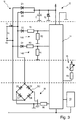
- ein schematisches Blockdiagramm eines Ausführungsbeispiels einer erfindungsgemäßen Tür mit einem Ausführungsbeispiel eines erfindungsgemäßen elektromechanischen Antriebs zum Betätigen eines beweglichen Flügels,
- Fig. 2
- ein schematisches Blockdiagramm einer Auswerte- und Steuerelektronik für den erfindungsgemäßen elektromechanischen Antrieb zum Betätigen eines beweglichen Flügels aus
Fig. 1 , und - Fig. 3
- ein schematisches Blockdiagramm einer Notfallsteuerelektronik für die Auswerte- und Steuerelektronik aus
Fig. 2 .
- Fig. 1
- a schematic block diagram of an embodiment of a door according to the invention with an embodiment of an electromechanical drive according to the invention for actuating a movable leaf,
- Fig. 2
- a schematic block diagram of evaluation and control electronics for the electromechanical drive according to the invention for actuating a movable leaf
Fig. 1 , and - Fig. 3
- a schematic block diagram of an emergency control electronics for the evaluation and control electronics
Fig. 2 .
Wie aus
Wie aus
Wie aus
Im Normalbetrieb ist das Motorrelais 34 durch die anliegende Betriebsspannung UB bestromt, so dass der Relaiskontakt 34.1 die erste Motorklemme K1 mit der Hauptsteuerelektronik 30 verbindet. Der elektromechanische Antrieb 1 bewegt den Flügel 5 und öffnet die korrespondierende Tür, indem die zweite Auswerte- und Steuereinheit 32 den Elektromotor 22 durch Anlegen einer Eingangsspannung UE an die Motorklemmen K1, K2 beschleunigt. Somit wird der Flügel 5 mittels elektrischer Energie bewegt. Wird der Flügel 5 zum Öffnen der Tür manuell bewegt, so muss der Passant die Energie aufbringen, die als potentielle Energie im mechanischen Energiespeicher 28 gespeichert wird. Lässt der Passant den Flügel 5 los, dann schließt die gespeicherte Energie die Tür. Damit der Flügel 5 nicht ungebremst in die Schließlage schlägt, kann die Hauptsteuerelektronik 30 die Bremsvorrichtuna 20 einsetzen. um die Schließbeweauna des Flüaels 5 zu dämofen. DasIn normal operation, the
Schaltelement S1 kann beispielsweise als von der zweiten Auswerte- und Steuereinheit 32 angesteuerter elektronischer Schalter, wie beispielsweise als Feldeffekttransistor ausgeführt werden. Dadurch kann die Hauptsteuerelektronik 30 die Bauelemente der Notfallsteuerelektronik 10 auch während des Normalbetriebs zum Dämpfen der Bewegung des beweglichen Flügels 5 einsetzen. So kann die zweite Auswerte- und Steuereinheit 32 das Motorrelais 34 durch Öffnen des Schaltelements S1 von der Betriebsspannung trennen. Dadurch wechselt der Relaiskontakt 34.1 in den dargestellten stromlosen Schaltzustand und verbindet die Motorklemmen K1, K2 mit der Notfallelektronik 10, so dass die erste Auswerte- und Steuereinheit 11 die Bewegung des beweglichen Flügels 5 über den Bremsstromkreis 18 dämpfen kann.Switching element S1 can, for example, be designed as an electronic switch controlled by the second evaluation and
Wie aus
Wie aus
Mit der Aktivierung des Notfallbetriebs sind die Motorklemmen K1, K2 geöffnet und elektrische Energie wird in den Kondensator C der Ladeschaltung 12 geladen. Die im Kondensator C gespeicherte Energie wird zur Energieversorgung der Notfallsteuerelektronik 10 verwendet. Zudem bestimmt die erste Auswerte- und Steuereinheit 11 während die Motorklemmen K1, K2 offen sind über den ersten oder zweiten Messkreis 14A, 14B die Winkelgeschwindigkeit des Elektromotors 22, also die Geschwindigkeit des Flügels 5. Zusätzlich kann die Auswerte- und Steuereinheit 11 über den dritten Messkreis 16 die Position bzw. die Geschwindigkeit des Flügels 5 bestimmen.How out
When the emergency mode is activated, the motor terminals K1, K2 are open and electrical energy is charged into the capacitor C of the charging
Zur Dämpfung der Bewegung des Flügels 4 schließt die erste Auswerte- und Steuereinheit 11 die Motorklemmen K1. K2 über den Feldeffekttransistor FET kurz. Während des Kurzschlusses wird die Winkelgeschwindigkeit des Elektromotors 22 gedämpft. Durch die Pulsweitenmodulation des Kurzschlussstromes IA stellt die erste Auswerte- und Steuereinheit 11 im Notfallbetrieb die Dämpfung der Geschwindigkeit und somit die Bremskraft ein und sorgt für das Nachladen ihrer Energieversorgung. Im Notfallbetrieb stellt die erste Auswerte- und Steuereinheit 11 die Dämpfung der Bewegung des Flügels 5 in Abhängigkeit vom aktuellen Betriebszustand des elektromechanischen Antriebs 1 und/oder von einer aktuellen Bewegungsrichtung und/oder einer aktuellen Geschwindigkeit und/oder eines aktuellen Öffnungswinkels des Flügels 5 ein. Des Weiteren sorgt die erste Auswerteund Steuereinheit 11 im Notfallbetrieb durch Regelung der Schließgeschwindigkeit als Funktion vom Öffnungswinkel des Flügels 5 für die gewünschte Schließzeit von beispielsweise 5 Sekunden. Die Schließzeit ist somit unabhängig von Temperatur, Alterung und Reibung. Das bedeutet, dass die erste Auswerte- und Steuereinheit 11 die Dämpfung der Bewegung des Flügels 5 in Abhängigkeit von einem aktuellen Betriebszustand des elektrischen Antriebs 1 und/oder einer aktuellen Bewegungsrichtung und/oder einer aktuellen Geschwindigkeit und/oder eines aktuellen Öffnungswinkels des Flügels 5 einstellt.To dampen the movement of the wing 4, the first evaluation and
Die erste Auswerte- und Steuereinheit 11 dämpft eine automatische Öffnungsbewegung des Flügels 5 für eine vorgegebene erste Zeitdauer von beispielsweise ca. 3 Sekunden mit einer maximalen Bremskraft, wenn während der automatischen Öffnungsbewegung des Flügels 5 der Notfallbetrieb eintritt. Nach Ablauf der vorgegebenen ersten Zeitdauer von ca. 3 Sekunden begrenzt die erste Auswerte- und Steuereinheit 1 die weitere Öffnungsbewegung des Flügels 5 auf eine maximale Öffnungsgeschwindigkeit. Wenn während der manuellen Öffnungsbewegung der Notfallbetrieb eintritt, begrenzt die erste Auswerte- und Steuereinheit 11 eine manuelle Öffnungsbewegung des Flügels 5 auf eine maximale Öffnungsgeschwindigkeit. Dadurch kann in vorteilhafter Weise die Gefahr reduziert werden, dass der Flügel 5 ungebremst in die Offenlage schlägt oder eine Person hinter dem Flügel verletzt.The first evaluation and
Wenn während der Schließbewegung des Flügels 5 der Notfallbetrieb eintritt, begrenzt die erste Auswerte- und Steuereinheit 11 die Schließbeweauna des Flüaels 5 auf eine maximale Schließgeschwindigkeit. Die erste Auswerte- und Steuereinheit 11 beendet die Dämpfung der Schließbewegung des Flügels 5, wenn der Flügel 5 mindestens eine vorgegebene Endschlagbedingung erreicht hat. Als Endschlagbedingung kann beispielsweise eine Endschlaggeschwindigkeit und/oder eine Endschlagposition vorgegeben werden.If emergency operation occurs during the closing movement of the
Die zweite Auswerte- und Steuereinheit 32 der Hauptsteuerelektronik 30 kommuniziert im Normalbetrieb über entsprechende Kommunikationsverbindungen mit der ersten Auswerte- und Steuereinheit 11 der Notfallsteuerelektronik 10 und gibt Informationen über den aktuellen Betriebszustand des elektromechanischen Antriebs 1 an die erste Auswerte- und Steuereinheit 11 aus. Zudem kann die zweite Auswerte- und Steuereinheit 32 Parameter und/oder Grenzwerte zur Dämpfung der Bewegung des Flügels 5 an die erste Auswerteund Steuereinheit 11 ausgeben. Im dargestellten Ausführungsbeispiel speichert die erste Auswerte- und Steuereinheit 11 die Parameter und/oder Grenzwerte zur Dämpfung der Bewegung des Flügels 5 in einem nichtflüchtigen Speicher 19. Zudem inkrementiert die erste Auswerte- und Steuereinheit 11 mit jedem Öffnungszyklus des Flügels 5 einen Zähler im nichtflüchtigen Speicher 19. Außerdem können bei Bedarf Wartungsdaten in den nichtflüchtigen Datenspeicher 19 geschrieben und aus diesem gelesen werden. Dies gilt auch für den Stand des Zyklenzählers im Datenspeicher 19.The second evaluation and
Ausführungsformen des erfindungsgemäßen elektromechanischen Antriebs 1 können vorzugweise für Brandschutztüren eingesetzt werden.
Claims (18)
- Electromechanical drive (1) comprising an electric motor (22) for actuating a movable wing (5) with the electric motor (22), the motor shaft (24) of which is operatively connected to the wing (5) in the mounted state of the drive (1) via a force transmission apparatus, such that a movement of the motor shaft (24) brings about a movement of the wing (5), a mechanical energy storage unit that is charged through an opening movement of the wing (5) and is discharged through a closing movement of the movable wing (5), and a braking device (20) by way of which the movement of the wing (5) is able to be braked by virtue of the electric motor (22) being able to be operated as a generator, wherein the movement of the wing (5) gives rise, at motor terminals (K1, K2) of the electric motor (22) operated as a generator, to a motion-dependent output voltage (UA) that is applied to a brake circuit (18), wherein the brake circuit (18) has at least one switching element (FET) by way of which the motor terminals (K1, K2) are able to be short-circuited,
characterizedin that, in an emergency mode, the output voltage (UA) of the electric motor (22) operated as a generator is applied to a charging circuit (12) that stores electrical energy in a capacitor (C) for supplying energy to emergency control electronics (10),wherein a first evaluation and control unit (11) of the emergency control electronics (10) also sets an effective braking force for damping the movement of the wing (5) via the switching element designed as a field-effect transistor (FET) andthe first evaluation and control unit (11) performs pulse-width modulation on the motor current (IA) via the field-effect transistor (FET). - Drive according to Claim 1,
characterized
in that a motor relay (34) activates the emergency mode via at least one relay contact (34.1) in the event of a grid failure and/or in the event of an alarm. - Drive according to Claim 2,
characterized
in that the at least one relay contact (34.1) connects the motor terminals (K1, K2) to main control electronics (30) in normal mode and connects said motor terminals to the emergency electronics (10), comprising the charging circuit (12), in emergency mode. - Drive according to one of Claims 1 to 3,
characterized
in that a second evaluation and control unit (32) of the main control electronics (30), in normal mode, communicates with the first evaluation and control unit (11) of the emergency control electronics (10) via appropriate communication connections and outputs information about the current operating state of the electromechanical drive (1) to the first evaluation and control electronics (11). - Drive according to one of Claims 1 to 4,
characterized
in that the first evaluation and control unit (11) sets the damping of the movement of the wing (5) on the basis of the current operating state of the electromechanical drive (1) and/or of a current direction of movement and/or a current speed and/or a current opening angle of the wing (5). - Drive according to Claim 5,
characterized
in that the first evaluation and control unit (11) determines a current direction of movement and speed of the wing (5) from the output voltage (UA) via at least one measurement circuit (14A, 14B). - Drive according to Claim 6,
characterized
in that at least one first measurement circuit (14A) identifies an opening movement of the wing (5) and outputs a measured variable for determining the opening speed of the wing (5) to the first evaluation and control unit (11). - Drive according to Claim 6 or 7,
characterized
in that at least one second measurement circuit (14B) identifies a closing movement of the wing (5) and outputs a measured variable for determining the closing speed of the wing (5) to the first evaluation and control unit (11) . - Drive according to one of Claims 5 to 8,
characterized
in that at least one third measurement circuit (16) comprises a position sensor (RP) that outputs a measured variable for determining a current opening angle and/or a current speed of the wing (5) to the first evaluation and control unit (11). - Drive according to one of Claims 1 to 9.
characterized
in that the first evaluation and control unit (11) damps an automatic opening movement of the wing (5) with a maximum braking force for a predefined first duration and, after the predefined first duration has elapsed, limits the further opening angle of the wing (5) to a maximum opening speed when the emergency mode occurs during the automatic opening movement of the wing (5). - Drive according to one of Claims 1 to 10,
characterized
in that the first evaluation and control unit (11) limits a manual opening movement of the wing (5) to a maximum opening speed when the emergency mode occurs during the manual opening movement. - Drive according to one of Claims 1 to 11,
characterized
in that the first evaluation and control unit (11) limits the closing movement of the wing (5) to a maximum closing speed when the emergency mode occurs during the closing movement. - Drive according to Claim 12,
characterized
in that the evaluation and control unit (11) ends the damping of the closing movement of the wing (5) when the wing (5) has achieved at least one predefined end stop condition. - Drive according to Claim 13,
characterized
in that an end stop speed and/or an end stop position are predefined as end stop condition. - Drive according to one of Claims 4 to 14,
characterized
in that the second evaluation and control unit (32) outputs parameters and/or limit values for damping the movement of the wing (5) to the first evaluation and control unit (11). - Drive according to Claim 15,
characterized
in that the first evaluation and control unit (11) stores the parameters and/or limit values for damping the movement of the wing (5) in a non-volatile memory (19). - Drive according to Claim 15 or 16,
characterized
in that the first evaluation and control unit (11) increments a counter in the non-volatile memory (19) with each opening cycle of the wing (5). - Door having at least one movable wing (5) and an electromechanical drive (1) for actuating the movable wing (5),
characterized
in that the electromechanical drive (1) is designed in accordance with at least one of Claims 1 to 17.
Priority Applications (1)
| Application Number | Priority Date | Filing Date | Title |
|---|---|---|---|
| PL15804388T PL3245732T3 (en) | 2015-01-13 | 2015-12-01 | Electromechanical drive for actuating a moveable wing and corresponding door |
Applications Claiming Priority (2)
| Application Number | Priority Date | Filing Date | Title |
|---|---|---|---|
| DE102015200289.6A DE102015200289B4 (en) | 2015-01-13 | 2015-01-13 | Electromechanical actuator for actuating a movable sash and corresponding door |
| PCT/EP2015/078168 WO2016113031A1 (en) | 2015-01-13 | 2015-12-01 | Electromechanical drive for actuating a moveable wing and corresponding door |
Publications (2)
| Publication Number | Publication Date |
|---|---|
| EP3245732A1 EP3245732A1 (en) | 2017-11-22 |
| EP3245732B1 true EP3245732B1 (en) | 2021-09-29 |
Family
ID=54780277
Family Applications (1)
| Application Number | Title | Priority Date | Filing Date |
|---|---|---|---|
| EP15804388.5A Active EP3245732B1 (en) | 2015-01-13 | 2015-12-01 | Electromechanical drive for actuating a moveable wing and corresponding door |
Country Status (5)
| Country | Link |
|---|---|
| EP (1) | EP3245732B1 (en) |
| DE (1) | DE102015200289B4 (en) |
| DK (1) | DK3245732T3 (en) |
| PL (1) | PL3245732T3 (en) |
| WO (1) | WO2016113031A1 (en) |
Cited By (2)
| Publication number | Priority date | Publication date | Assignee | Title |
|---|---|---|---|---|
| EP4350971A1 (en) | 2022-10-07 | 2024-04-10 | dormakaba Deutschland GmbH | Electromechanical drive for actuating a leaf movably mounted on a structural element |
| EP4350970A1 (en) | 2022-10-07 | 2024-04-10 | dormakaba Deutschland GmbH | Method for determining at least one property of a rotary movement of a three-phase ac machine in generator operation, and electromechanical drive |
Families Citing this family (9)
| Publication number | Priority date | Publication date | Assignee | Title |
|---|---|---|---|---|
| EP3104518B2 (en) | 2015-06-10 | 2021-07-28 | Belimo Holding AG | Control circuit for a safety drive |
| DE102016202225A1 (en) | 2016-02-15 | 2017-08-17 | Geze Gmbh | Braking device for a movable door leaf and corresponding door closer |
| DE102017201944A1 (en) * | 2017-02-08 | 2018-08-09 | Geze Gmbh | braking device |
| DE102017201950A1 (en) * | 2017-02-08 | 2018-08-09 | Geze Gmbh | braking device |
| DE102017201953A1 (en) * | 2017-02-08 | 2018-08-09 | Geze Gmbh | Drive device for a door or window sash |
| DE102017201942A1 (en) | 2017-02-08 | 2018-08-09 | Geze Gmbh | Locking and / or emergency opening system |
| DE102017103920A1 (en) | 2017-02-24 | 2018-08-30 | Petz Industries Gmbh & Co. Kg | actuator |
| DE102017210434A1 (en) * | 2017-06-21 | 2018-12-27 | Geze Gmbh | Electric door drive and security door |
| DE102022108617A1 (en) | 2022-04-08 | 2023-10-12 | Brose Fahrzeugteile Se & Co. Kommanditgesellschaft, Bamberg | Drive arrangement for motor-driven adjustment of a motor vehicle flap |
Family Cites Families (7)
| Publication number | Priority date | Publication date | Assignee | Title |
|---|---|---|---|---|
| AU2002952885A0 (en) * | 2002-11-25 | 2002-12-12 | Turbocor Inc | High speed electric motor power supply |
| DE102005028007B4 (en) | 2005-06-16 | 2009-05-07 | Geze Gmbh | Drive for actuating a movable wing, in particular a door |
| DE102005049488B8 (en) * | 2005-10-13 | 2007-02-15 | Grass Gmbh | Device and method for closing or opening and closing at least one drawer, flap, door or the like |
| JP5281513B2 (en) * | 2009-07-30 | 2013-09-04 | シロキ工業株式会社 | Driving device for vehicle opening / closing body |
| DE102011004019B4 (en) | 2011-02-14 | 2015-02-12 | Siemens Aktiengesellschaft | Electrically powered door |
| JP5993610B2 (en) * | 2012-05-08 | 2016-09-14 | アズビル株式会社 | Electric actuator |
| EP3104518B2 (en) * | 2015-06-10 | 2021-07-28 | Belimo Holding AG | Control circuit for a safety drive |
-
2015
- 2015-01-13 DE DE102015200289.6A patent/DE102015200289B4/en active Active
- 2015-12-01 WO PCT/EP2015/078168 patent/WO2016113031A1/en active Application Filing
- 2015-12-01 PL PL15804388T patent/PL3245732T3/en unknown
- 2015-12-01 EP EP15804388.5A patent/EP3245732B1/en active Active
- 2015-12-01 DK DK15804388.5T patent/DK3245732T3/en active
Cited By (3)
| Publication number | Priority date | Publication date | Assignee | Title |
|---|---|---|---|---|
| EP4350971A1 (en) | 2022-10-07 | 2024-04-10 | dormakaba Deutschland GmbH | Electromechanical drive for actuating a leaf movably mounted on a structural element |
| EP4350970A1 (en) | 2022-10-07 | 2024-04-10 | dormakaba Deutschland GmbH | Method for determining at least one property of a rotary movement of a three-phase ac machine in generator operation, and electromechanical drive |
| WO2024074644A1 (en) | 2022-10-07 | 2024-04-11 | Dormakaba Deutschland Gmbh | Electromechanical drive for actuating a sash mounted moveably on a structure element |
Also Published As
| Publication number | Publication date |
|---|---|
| DE102015200289B4 (en) | 2018-03-01 |
| PL3245732T3 (en) | 2022-02-14 |
| EP3245732A1 (en) | 2017-11-22 |
| DK3245732T3 (en) | 2021-11-22 |
| DE102015200289A1 (en) | 2016-07-14 |
| WO2016113031A1 (en) | 2016-07-21 |
Similar Documents
| Publication | Publication Date | Title |
|---|---|---|
| EP3245732B1 (en) | Electromechanical drive for actuating a moveable wing and corresponding door | |
| EP3245728B1 (en) | Braking element for a moveable door leaf and a corresponding door closer | |
| EP3417135B1 (en) | Braking device for a moving door leaf and corresponding door closer | |
| EP0966782B1 (en) | Method for electronic control and adjustment of the movement of electrically actuated units | |
| EP2267881B1 (en) | Brake switch for a door actuator with an electric motor operated as generator | |
| EP1941120B1 (en) | Drive for actuating a moving wing, particularly a door | |
| DE102005028007B4 (en) | Drive for actuating a movable wing, in particular a door | |
| DE102016210780B4 (en) | Brake device for a movable door leaf and corresponding door | |
| DE102013002245A1 (en) | Control device for DC motor | |
| WO2010124927A2 (en) | Method and device for detecting an entrapment situation | |
| DE4315637A1 (en) | Method for detecting the position, the direction (sense) of rotation and/or the speed of rotation of a rotatably mounted part | |
| DE4318128A1 (en) | Process for the electronic monitoring and control of the opening and closing process of electrically operated units | |
| DE102011107866A1 (en) | Method for operating a building closure | |
| EP3361620B1 (en) | Braking device | |
| DE102017201955A1 (en) | braking device | |
| EP3361621A1 (en) | Braking device | |
| EP0468361B1 (en) | Limitation of closing force at the closing edge of a movable element | |
| EP3361034A1 (en) | Fixing and/or emergency opening system | |
| DE10044029A1 (en) | Control arrangement of an AC blind motor or an AC tubular motor | |
| DE102013103950B3 (en) | Door i.e. revolving door, has brake arm generating voltage between base and emitter of transistor over closing movement of revolving door wing of generator by switching on and off of electromotor | |
| DE102010010354B3 (en) | Window lifter arrangement for use in motor vehicle, has controllers formed such that reference speed of window lifter motors is increased when duty cycle of pulse modulation of window lifter motors falls below fixed threshold value | |
| DE10142431A1 (en) | Controller for high speed gate, generates demand value for output frequency from absolute position sensor data and force-time profiles stored in control unit and controls gate movement | |
| EP3361027B1 (en) | Locking device | |
| DE102016208596A1 (en) | Method for operating a locking device and a locking device | |
| DE102017118173A1 (en) | Method and device for operating a brushless DC motor |
Legal Events
| Date | Code | Title | Description |
|---|---|---|---|
| STAA | Information on the status of an ep patent application or granted ep patent |
Free format text: STATUS: THE INTERNATIONAL PUBLICATION HAS BEEN MADE |
|
| PUAI | Public reference made under article 153(3) epc to a published international application that has entered the european phase |
Free format text: ORIGINAL CODE: 0009012 |
|
| STAA | Information on the status of an ep patent application or granted ep patent |
Free format text: STATUS: REQUEST FOR EXAMINATION WAS MADE |
|
| 17P | Request for examination filed |
Effective date: 20170710 |
|
| AK | Designated contracting states |
Kind code of ref document: A1 Designated state(s): AL AT BE BG CH CY CZ DE DK EE ES FI FR GB GR HR HU IE IS IT LI LT LU LV MC MK MT NL NO PL PT RO RS SE SI SK SM TR |
|
| AX | Request for extension of the european patent |
Extension state: BA ME |
|
| RIN1 | Information on inventor provided before grant (corrected) |
Inventor name: FISCHER, MANUEL Inventor name: KATZ, EUGEN Inventor name: HUCKER, MATTHIAS Inventor name: HAEGELE, VOLKER Inventor name: HAHN, ERHARD |
|
| DAV | Request for validation of the european patent (deleted) | ||
| DAX | Request for extension of the european patent (deleted) | ||
| STAA | Information on the status of an ep patent application or granted ep patent |
Free format text: STATUS: EXAMINATION IS IN PROGRESS |
|
| 17Q | First examination report despatched |
Effective date: 20191203 |
|
| STAA | Information on the status of an ep patent application or granted ep patent |
Free format text: STATUS: EXAMINATION IS IN PROGRESS |
|
| REG | Reference to a national code |
Ref country code: DE Ref legal event code: R079 Free format text: PREVIOUS MAIN CLASS: H02P0029020000 Ipc: E05F0015720000 |
|
| GRAP | Despatch of communication of intention to grant a patent |
Free format text: ORIGINAL CODE: EPIDOSNIGR1 |
|
| STAA | Information on the status of an ep patent application or granted ep patent |
Free format text: STATUS: GRANT OF PATENT IS INTENDED |
|
| RIC1 | Information provided on ipc code assigned before grant |
Ipc: H02P 3/14 20060101ALI20210416BHEP Ipc: H02P 3/12 20060101ALI20210416BHEP Ipc: H02P 29/024 20160101ALI20210416BHEP Ipc: E05F 15/72 20150101AFI20210416BHEP |
|
| INTG | Intention to grant announced |
Effective date: 20210517 |
|
| GRAS | Grant fee paid |
Free format text: ORIGINAL CODE: EPIDOSNIGR3 |
|
| GRAA | (expected) grant |
Free format text: ORIGINAL CODE: 0009210 |
|
| STAA | Information on the status of an ep patent application or granted ep patent |
Free format text: STATUS: THE PATENT HAS BEEN GRANTED |
|
| AK | Designated contracting states |
Kind code of ref document: B1 Designated state(s): AL AT BE BG CH CY CZ DK EE ES FI FR GB GR HR HU IE IS IT LI LT LU LV MC MK MT NL NO PL PT RO RS SE SI SK SM TR |
|
| RBV | Designated contracting states (corrected) |
Designated state(s): AL AT BE BG CH CY CZ DK EE ES FI FR GB GR HR HU IE IS IT LI LT LU LV MC MK MT NL NO PL PT RO RS SE SI SK SM TR |
|
| REG | Reference to a national code |
Ref country code: DE Ref legal event code: R108 Ref country code: GB Ref legal event code: FG4D Free format text: NOT ENGLISH |
|
| REG | Reference to a national code |
Ref country code: CH Ref legal event code: EP Ref country code: AT Ref legal event code: REF Ref document number: 1434336 Country of ref document: AT Kind code of ref document: T Effective date: 20211015 |
|
| REG | Reference to a national code |
Ref country code: IE Ref legal event code: FG4D Free format text: LANGUAGE OF EP DOCUMENT: GERMAN |
|
| REG | Reference to a national code |
Ref country code: DK Ref legal event code: T3 Effective date: 20211116 |
|
| REG | Reference to a national code |
Ref country code: NO Ref legal event code: T2 Effective date: 20210929 |
|
| REG | Reference to a national code |
Ref country code: LT Ref legal event code: MG9D |
|
| PG25 | Lapsed in a contracting state [announced via postgrant information from national office to epo] |
Ref country code: HR Free format text: LAPSE BECAUSE OF FAILURE TO SUBMIT A TRANSLATION OF THE DESCRIPTION OR TO PAY THE FEE WITHIN THE PRESCRIBED TIME-LIMIT Effective date: 20210929 Ref country code: SE Free format text: LAPSE BECAUSE OF FAILURE TO SUBMIT A TRANSLATION OF THE DESCRIPTION OR TO PAY THE FEE WITHIN THE PRESCRIBED TIME-LIMIT Effective date: 20210929 Ref country code: RS Free format text: LAPSE BECAUSE OF FAILURE TO SUBMIT A TRANSLATION OF THE DESCRIPTION OR TO PAY THE FEE WITHIN THE PRESCRIBED TIME-LIMIT Effective date: 20210929 Ref country code: LT Free format text: LAPSE BECAUSE OF FAILURE TO SUBMIT A TRANSLATION OF THE DESCRIPTION OR TO PAY THE FEE WITHIN THE PRESCRIBED TIME-LIMIT Effective date: 20210929 Ref country code: BG Free format text: LAPSE BECAUSE OF FAILURE TO SUBMIT A TRANSLATION OF THE DESCRIPTION OR TO PAY THE FEE WITHIN THE PRESCRIBED TIME-LIMIT Effective date: 20211229 Ref country code: FI Free format text: LAPSE BECAUSE OF FAILURE TO SUBMIT A TRANSLATION OF THE DESCRIPTION OR TO PAY THE FEE WITHIN THE PRESCRIBED TIME-LIMIT Effective date: 20210929 |
|
| REG | Reference to a national code |
Ref country code: NL Ref legal event code: MP Effective date: 20210929 |
|
| PG25 | Lapsed in a contracting state [announced via postgrant information from national office to epo] |
Ref country code: LV Free format text: LAPSE BECAUSE OF FAILURE TO SUBMIT A TRANSLATION OF THE DESCRIPTION OR TO PAY THE FEE WITHIN THE PRESCRIBED TIME-LIMIT Effective date: 20210929 Ref country code: GR Free format text: LAPSE BECAUSE OF FAILURE TO SUBMIT A TRANSLATION OF THE DESCRIPTION OR TO PAY THE FEE WITHIN THE PRESCRIBED TIME-LIMIT Effective date: 20211230 |
|
| PG25 | Lapsed in a contracting state [announced via postgrant information from national office to epo] |
Ref country code: IS Free format text: LAPSE BECAUSE OF FAILURE TO SUBMIT A TRANSLATION OF THE DESCRIPTION OR TO PAY THE FEE WITHIN THE PRESCRIBED TIME-LIMIT Effective date: 20220129 Ref country code: SK Free format text: LAPSE BECAUSE OF FAILURE TO SUBMIT A TRANSLATION OF THE DESCRIPTION OR TO PAY THE FEE WITHIN THE PRESCRIBED TIME-LIMIT Effective date: 20210929 Ref country code: RO Free format text: LAPSE BECAUSE OF FAILURE TO SUBMIT A TRANSLATION OF THE DESCRIPTION OR TO PAY THE FEE WITHIN THE PRESCRIBED TIME-LIMIT Effective date: 20210929 Ref country code: PT Free format text: LAPSE BECAUSE OF FAILURE TO SUBMIT A TRANSLATION OF THE DESCRIPTION OR TO PAY THE FEE WITHIN THE PRESCRIBED TIME-LIMIT Effective date: 20220131 Ref country code: NL Free format text: LAPSE BECAUSE OF FAILURE TO SUBMIT A TRANSLATION OF THE DESCRIPTION OR TO PAY THE FEE WITHIN THE PRESCRIBED TIME-LIMIT Effective date: 20210929 Ref country code: ES Free format text: LAPSE BECAUSE OF FAILURE TO SUBMIT A TRANSLATION OF THE DESCRIPTION OR TO PAY THE FEE WITHIN THE PRESCRIBED TIME-LIMIT Effective date: 20210929 Ref country code: EE Free format text: LAPSE BECAUSE OF FAILURE TO SUBMIT A TRANSLATION OF THE DESCRIPTION OR TO PAY THE FEE WITHIN THE PRESCRIBED TIME-LIMIT Effective date: 20210929 Ref country code: CZ Free format text: LAPSE BECAUSE OF FAILURE TO SUBMIT A TRANSLATION OF THE DESCRIPTION OR TO PAY THE FEE WITHIN THE PRESCRIBED TIME-LIMIT Effective date: 20210929 Ref country code: AL Free format text: LAPSE BECAUSE OF FAILURE TO SUBMIT A TRANSLATION OF THE DESCRIPTION OR TO PAY THE FEE WITHIN THE PRESCRIBED TIME-LIMIT Effective date: 20210929 |
|
| PG25 | Lapsed in a contracting state [announced via postgrant information from national office to epo] |
Ref country code: MC Free format text: LAPSE BECAUSE OF FAILURE TO SUBMIT A TRANSLATION OF THE DESCRIPTION OR TO PAY THE FEE WITHIN THE PRESCRIBED TIME-LIMIT Effective date: 20210929 |
|
| REG | Reference to a national code |
Ref country code: CH Ref legal event code: PL |
|
| PLBE | No opposition filed within time limit |
Free format text: ORIGINAL CODE: 0009261 |
|
| STAA | Information on the status of an ep patent application or granted ep patent |
Free format text: STATUS: NO OPPOSITION FILED WITHIN TIME LIMIT |
|
| GBPC | Gb: european patent ceased through non-payment of renewal fee |
Effective date: 20211229 |
|
| 26N | No opposition filed |
Effective date: 20220630 |
|
| REG | Reference to a national code |
Ref country code: BE Ref legal event code: MM Effective date: 20211231 |
|
| PG25 | Lapsed in a contracting state [announced via postgrant information from national office to epo] |
Ref country code: LU Free format text: LAPSE BECAUSE OF NON-PAYMENT OF DUE FEES Effective date: 20211201 Ref country code: IE Free format text: LAPSE BECAUSE OF NON-PAYMENT OF DUE FEES Effective date: 20211201 Ref country code: GB Free format text: LAPSE BECAUSE OF NON-PAYMENT OF DUE FEES Effective date: 20211229 |
|
| PG25 | Lapsed in a contracting state [announced via postgrant information from national office to epo] |
Ref country code: SI Free format text: LAPSE BECAUSE OF FAILURE TO SUBMIT A TRANSLATION OF THE DESCRIPTION OR TO PAY THE FEE WITHIN THE PRESCRIBED TIME-LIMIT Effective date: 20210929 Ref country code: FR Free format text: LAPSE BECAUSE OF NON-PAYMENT OF DUE FEES Effective date: 20211231 Ref country code: BE Free format text: LAPSE BECAUSE OF NON-PAYMENT OF DUE FEES Effective date: 20211231 |
|
| PG25 | Lapsed in a contracting state [announced via postgrant information from national office to epo] |
Ref country code: LI Free format text: LAPSE BECAUSE OF NON-PAYMENT OF DUE FEES Effective date: 20211231 Ref country code: CH Free format text: LAPSE BECAUSE OF NON-PAYMENT OF DUE FEES Effective date: 20211231 |
|
| PGFP | Annual fee paid to national office [announced via postgrant information from national office to epo] |
Ref country code: PL Payment date: 20221122 Year of fee payment: 8 |
|
| PG25 | Lapsed in a contracting state [announced via postgrant information from national office to epo] |
Ref country code: HU Free format text: LAPSE BECAUSE OF FAILURE TO SUBMIT A TRANSLATION OF THE DESCRIPTION OR TO PAY THE FEE WITHIN THE PRESCRIBED TIME-LIMIT; INVALID AB INITIO Effective date: 20151201 |
|
| P01 | Opt-out of the competence of the unified patent court (upc) registered |
Effective date: 20230510 |
|
| PG25 | Lapsed in a contracting state [announced via postgrant information from national office to epo] |
Ref country code: CY Free format text: LAPSE BECAUSE OF FAILURE TO SUBMIT A TRANSLATION OF THE DESCRIPTION OR TO PAY THE FEE WITHIN THE PRESCRIBED TIME-LIMIT Effective date: 20210929 |
|
| PG25 | Lapsed in a contracting state [announced via postgrant information from national office to epo] |
Ref country code: SM Free format text: LAPSE BECAUSE OF FAILURE TO SUBMIT A TRANSLATION OF THE DESCRIPTION OR TO PAY THE FEE WITHIN THE PRESCRIBED TIME-LIMIT Effective date: 20210929 |
|
| PGFP | Annual fee paid to national office [announced via postgrant information from national office to epo] |
Ref country code: NO Payment date: 20231222 Year of fee payment: 9 Ref country code: IT Payment date: 20231228 Year of fee payment: 9 Ref country code: DK Payment date: 20231227 Year of fee payment: 9 Ref country code: AT Payment date: 20231221 Year of fee payment: 9 |
|
| PGFP | Annual fee paid to national office [announced via postgrant information from national office to epo] |
Ref country code: PL Payment date: 20231123 Year of fee payment: 9 |