EP3361034A1 - Fixing and/or emergency opening system - Google Patents
Fixing and/or emergency opening system Download PDFInfo
- Publication number
- EP3361034A1 EP3361034A1 EP17207597.0A EP17207597A EP3361034A1 EP 3361034 A1 EP3361034 A1 EP 3361034A1 EP 17207597 A EP17207597 A EP 17207597A EP 3361034 A1 EP3361034 A1 EP 3361034A1
- Authority
- EP
- European Patent Office
- Prior art keywords
- wing
- control
- electric motor
- plant according
- detecting
- Prior art date
- Legal status (The legal status is an assumption and is not a legal conclusion. Google has not performed a legal analysis and makes no representation as to the accuracy of the status listed.)
- Pending
Links
Images


Classifications
-
- E—FIXED CONSTRUCTIONS
- E05—LOCKS; KEYS; WINDOW OR DOOR FITTINGS; SAFES
- E05F—DEVICES FOR MOVING WINGS INTO OPEN OR CLOSED POSITION; CHECKS FOR WINGS; WING FITTINGS NOT OTHERWISE PROVIDED FOR, CONCERNED WITH THE FUNCTIONING OF THE WING
- E05F15/00—Power-operated mechanisms for wings
- E05F15/70—Power-operated mechanisms for wings with automatic actuation
- E05F15/72—Power-operated mechanisms for wings with automatic actuation responsive to emergency conditions, e.g. fire
-
- E—FIXED CONSTRUCTIONS
- E05—LOCKS; KEYS; WINDOW OR DOOR FITTINGS; SAFES
- E05F—DEVICES FOR MOVING WINGS INTO OPEN OR CLOSED POSITION; CHECKS FOR WINGS; WING FITTINGS NOT OTHERWISE PROVIDED FOR, CONCERNED WITH THE FUNCTIONING OF THE WING
- E05F15/00—Power-operated mechanisms for wings
- E05F15/60—Power-operated mechanisms for wings using electrical actuators
- E05F15/603—Power-operated mechanisms for wings using electrical actuators using rotary electromotors
- E05F15/611—Power-operated mechanisms for wings using electrical actuators using rotary electromotors for swinging wings
- E05F15/63—Power-operated mechanisms for wings using electrical actuators using rotary electromotors for swinging wings operated by swinging arms
-
- E—FIXED CONSTRUCTIONS
- E05—LOCKS; KEYS; WINDOW OR DOOR FITTINGS; SAFES
- E05F—DEVICES FOR MOVING WINGS INTO OPEN OR CLOSED POSITION; CHECKS FOR WINGS; WING FITTINGS NOT OTHERWISE PROVIDED FOR, CONCERNED WITH THE FUNCTIONING OF THE WING
- E05F3/00—Closers or openers with braking devices, e.g. checks; Construction of pneumatic or liquid braking devices
- E05F3/22—Additional arrangements for closers, e.g. for holding the wing in opened or other position
- E05F3/221—Mechanical power-locks, e.g. for holding the wing open or for free-moving zones
- E05F3/222—Mechanical power-locks, e.g. for holding the wing open or for free-moving zones electrically operated
-
- H—ELECTRICITY
- H02—GENERATION; CONVERSION OR DISTRIBUTION OF ELECTRIC POWER
- H02K—DYNAMO-ELECTRIC MACHINES
- H02K11/00—Structural association of dynamo-electric machines with electric components or with devices for shielding, monitoring or protection
- H02K11/30—Structural association with control circuits or drive circuits
-
- H—ELECTRICITY
- H02—GENERATION; CONVERSION OR DISTRIBUTION OF ELECTRIC POWER
- H02K—DYNAMO-ELECTRIC MACHINES
- H02K51/00—Dynamo-electric gears, i.e. dynamo-electric means for transmitting mechanical power from a driving shaft to a driven shaft and comprising structurally interrelated motor and generator parts
-
- H—ELECTRICITY
- H02—GENERATION; CONVERSION OR DISTRIBUTION OF ELECTRIC POWER
- H02K—DYNAMO-ELECTRIC MACHINES
- H02K7/00—Arrangements for handling mechanical energy structurally associated with dynamo-electric machines, e.g. structural association with mechanical driving motors or auxiliary dynamo-electric machines
- H02K7/10—Structural association with clutches, brakes, gears, pulleys or mechanical starters
- H02K7/102—Structural association with clutches, brakes, gears, pulleys or mechanical starters with friction brakes
- H02K7/1021—Magnetically influenced friction brakes
- H02K7/1023—Magnetically influenced friction brakes using electromagnets
-
- E—FIXED CONSTRUCTIONS
- E05—LOCKS; KEYS; WINDOW OR DOOR FITTINGS; SAFES
- E05F—DEVICES FOR MOVING WINGS INTO OPEN OR CLOSED POSITION; CHECKS FOR WINGS; WING FITTINGS NOT OTHERWISE PROVIDED FOR, CONCERNED WITH THE FUNCTIONING OF THE WING
- E05F15/00—Power-operated mechanisms for wings
- E05F15/60—Power-operated mechanisms for wings using electrical actuators
- E05F15/603—Power-operated mechanisms for wings using electrical actuators using rotary electromotors
- E05F15/611—Power-operated mechanisms for wings using electrical actuators using rotary electromotors for swinging wings
- E05F15/63—Power-operated mechanisms for wings using electrical actuators using rotary electromotors for swinging wings operated by swinging arms
- E05F2015/631—Power-operated mechanisms for wings using electrical actuators using rotary electromotors for swinging wings operated by swinging arms the end of the arm sliding in a track; Slider arms therefor
-
- E—FIXED CONSTRUCTIONS
- E05—LOCKS; KEYS; WINDOW OR DOOR FITTINGS; SAFES
- E05Y—INDEXING SCHEME RELATING TO HINGES OR OTHER SUSPENSION DEVICES FOR DOORS, WINDOWS OR WINGS AND DEVICES FOR MOVING WINGS INTO OPEN OR CLOSED POSITION, CHECKS FOR WINGS AND WING FITTINGS NOT OTHERWISE PROVIDED FOR, CONCERNED WITH THE FUNCTIONING OF THE WING
- E05Y2201/00—Constructional elements; Accessories therefore
- E05Y2201/20—Brakes; Disengaging means, e.g. clutches; Holders, e.g. locks; Stops; Accessories therefore
- E05Y2201/21—Brakes
-
- E—FIXED CONSTRUCTIONS
- E05—LOCKS; KEYS; WINDOW OR DOOR FITTINGS; SAFES
- E05Y—INDEXING SCHEME RELATING TO HINGES OR OTHER SUSPENSION DEVICES FOR DOORS, WINDOWS OR WINGS AND DEVICES FOR MOVING WINGS INTO OPEN OR CLOSED POSITION, CHECKS FOR WINGS AND WING FITTINGS NOT OTHERWISE PROVIDED FOR, CONCERNED WITH THE FUNCTIONING OF THE WING
- E05Y2201/00—Constructional elements; Accessories therefore
- E05Y2201/20—Brakes; Disengaging means, e.g. clutches; Holders, e.g. locks; Stops; Accessories therefore
- E05Y2201/218—Holders
-
- E—FIXED CONSTRUCTIONS
- E05—LOCKS; KEYS; WINDOW OR DOOR FITTINGS; SAFES
- E05Y—INDEXING SCHEME RELATING TO HINGES OR OTHER SUSPENSION DEVICES FOR DOORS, WINDOWS OR WINGS AND DEVICES FOR MOVING WINGS INTO OPEN OR CLOSED POSITION, CHECKS FOR WINGS AND WING FITTINGS NOT OTHERWISE PROVIDED FOR, CONCERNED WITH THE FUNCTIONING OF THE WING
- E05Y2201/00—Constructional elements; Accessories therefore
- E05Y2201/40—Motors; Magnets; Springs; Weights; Accessories therefore
- E05Y2201/404—Motors; Magnets; Springs; Weights; Accessories therefore characterised by the function
- E05Y2201/408—Motors; Magnets; Springs; Weights; Accessories therefore characterised by the function for braking
-
- E—FIXED CONSTRUCTIONS
- E05—LOCKS; KEYS; WINDOW OR DOOR FITTINGS; SAFES
- E05Y—INDEXING SCHEME RELATING TO HINGES OR OTHER SUSPENSION DEVICES FOR DOORS, WINDOWS OR WINGS AND DEVICES FOR MOVING WINGS INTO OPEN OR CLOSED POSITION, CHECKS FOR WINGS AND WING FITTINGS NOT OTHERWISE PROVIDED FOR, CONCERNED WITH THE FUNCTIONING OF THE WING
- E05Y2201/00—Constructional elements; Accessories therefore
- E05Y2201/40—Motors; Magnets; Springs; Weights; Accessories therefore
- E05Y2201/43—Motors
- E05Y2201/434—Electromotors; Details thereof
-
- E—FIXED CONSTRUCTIONS
- E05—LOCKS; KEYS; WINDOW OR DOOR FITTINGS; SAFES
- E05Y—INDEXING SCHEME RELATING TO HINGES OR OTHER SUSPENSION DEVICES FOR DOORS, WINDOWS OR WINGS AND DEVICES FOR MOVING WINGS INTO OPEN OR CLOSED POSITION, CHECKS FOR WINGS AND WING FITTINGS NOT OTHERWISE PROVIDED FOR, CONCERNED WITH THE FUNCTIONING OF THE WING
- E05Y2400/00—Electronic control; Power supply; Power or signal transmission; User interfaces
- E05Y2400/10—Electronic control
- E05Y2400/20—Electronic control of brakes, disengaging means, holders or stops
-
- E—FIXED CONSTRUCTIONS
- E05—LOCKS; KEYS; WINDOW OR DOOR FITTINGS; SAFES
- E05Y—INDEXING SCHEME RELATING TO HINGES OR OTHER SUSPENSION DEVICES FOR DOORS, WINDOWS OR WINGS AND DEVICES FOR MOVING WINGS INTO OPEN OR CLOSED POSITION, CHECKS FOR WINGS AND WING FITTINGS NOT OTHERWISE PROVIDED FOR, CONCERNED WITH THE FUNCTIONING OF THE WING
- E05Y2400/00—Electronic control; Power supply; Power or signal transmission; User interfaces
- E05Y2400/10—Electronic control
- E05Y2400/30—Electronic control of motors
- E05Y2400/302—Electronic control of motors during electromotoric braking
-
- E—FIXED CONSTRUCTIONS
- E05—LOCKS; KEYS; WINDOW OR DOOR FITTINGS; SAFES
- E05Y—INDEXING SCHEME RELATING TO HINGES OR OTHER SUSPENSION DEVICES FOR DOORS, WINDOWS OR WINGS AND DEVICES FOR MOVING WINGS INTO OPEN OR CLOSED POSITION, CHECKS FOR WINGS AND WING FITTINGS NOT OTHERWISE PROVIDED FOR, CONCERNED WITH THE FUNCTIONING OF THE WING
- E05Y2400/00—Electronic control; Power supply; Power or signal transmission; User interfaces
- E05Y2400/10—Electronic control
- E05Y2400/30—Electronic control of motors
- E05Y2400/32—Position control, detection or monitoring
-
- E—FIXED CONSTRUCTIONS
- E05—LOCKS; KEYS; WINDOW OR DOOR FITTINGS; SAFES
- E05Y—INDEXING SCHEME RELATING TO HINGES OR OTHER SUSPENSION DEVICES FOR DOORS, WINDOWS OR WINGS AND DEVICES FOR MOVING WINGS INTO OPEN OR CLOSED POSITION, CHECKS FOR WINGS AND WING FITTINGS NOT OTHERWISE PROVIDED FOR, CONCERNED WITH THE FUNCTIONING OF THE WING
- E05Y2400/00—Electronic control; Power supply; Power or signal transmission; User interfaces
- E05Y2400/10—Electronic control
- E05Y2400/52—Safety arrangements
-
- E—FIXED CONSTRUCTIONS
- E05—LOCKS; KEYS; WINDOW OR DOOR FITTINGS; SAFES
- E05Y—INDEXING SCHEME RELATING TO HINGES OR OTHER SUSPENSION DEVICES FOR DOORS, WINDOWS OR WINGS AND DEVICES FOR MOVING WINGS INTO OPEN OR CLOSED POSITION, CHECKS FOR WINGS AND WING FITTINGS NOT OTHERWISE PROVIDED FOR, CONCERNED WITH THE FUNCTIONING OF THE WING
- E05Y2400/00—Electronic control; Power supply; Power or signal transmission; User interfaces
- E05Y2400/60—Power supply; Power or signal transmission
- E05Y2400/61—Power supply
- E05Y2400/616—Generators
-
- E—FIXED CONSTRUCTIONS
- E05—LOCKS; KEYS; WINDOW OR DOOR FITTINGS; SAFES
- E05Y—INDEXING SCHEME RELATING TO HINGES OR OTHER SUSPENSION DEVICES FOR DOORS, WINDOWS OR WINGS AND DEVICES FOR MOVING WINGS INTO OPEN OR CLOSED POSITION, CHECKS FOR WINGS AND WING FITTINGS NOT OTHERWISE PROVIDED FOR, CONCERNED WITH THE FUNCTIONING OF THE WING
- E05Y2900/00—Application of doors, windows, wings or fittings thereof
- E05Y2900/10—Application of doors, windows, wings or fittings thereof for buildings or parts thereof
- E05Y2900/13—Application of doors, windows, wings or fittings thereof for buildings or parts thereof characterised by the type of wing
- E05Y2900/132—Doors
Definitions
- the invention relates to a system for detecting and / or emergency opening a wing of a door, a window or the like, with a drive with at least one mechanical energy storage, which is charged by an opening movement of the wing and discharged with a closing movement of the wing, at least one electric motor, the motor shaft is in operative connection with the wing, and a control and / or regulating electronics, via which the electric motor for regenerative damping of the wing movements can be controlled.
- Actuators or door closers for movable door leaves with a mechanical energy storage and hydraulic damping are well known.
- the mechanical energy store When the door leaf is opened manually, the mechanical energy store is charged with potential energy, which closes the released door leaf again.
- the mechanical energy storage may, for example, comprise a spring, which is tensioned by the manual opening of the door leaf and relaxes again with the closing of the door leaf.
- generator damped door closer with at least one operated as a generator electric motor whose motor shaft is operatively connected to the wing and the motor terminals can be shorted to attenuate the wing movements via a control or control electronics.
- a regenerated damped door closer usually also includes a spring acting as a mechanical reservoir.
- the spring When the door is opened manually, the spring is tensioned, which loads potential energy into the spring.
- the electric motor usually associated gear is rotated.
- the at least one electric motor is usually a brush-type one or brushless magnetically excited DC motor.
- this generates electrical energy for the control electronics from the wing movement.
- the movement of the door leaf can be damped by short-circuiting the motor windings on the control or regulating electronics.
- Such a regenerated damped door usually operates as a known hydraulically damped door closer self-sufficient, i. it does not require an external source of electrical power, either through the mains or through an accumulator.
- a locking device must cancel the self-closing feature of the door closer according to the current electrical current guidelines.
- the triggering device of a fire switching center switches off the electrical energy, whereby the locking device triggers and the door leaf is closed by the spring forming the mechanical memory. If there is no electrical energy at the locking device, the door closes after manual opening. The closing of the door is controlled, i. E. attenuated.
- a door closer If a door closer is installed on a supply air door, it usually works like a conventional door closer. In the event of an alarm, such as a fire or smoke occurring, a smoke-heat extraction system provides electrical energy, which opens the air supply door against the force of the spring of the door closer. The relevant building is hereby thereby used with the corresponding exhaust windows.
- a Zu Kunststofföffner is previously mounted in addition to the hydraulic door closer, which usually includes a motor-gear unit that opens the door leaf via a lever or a roller.
- Supply air opener and door closer must be decoupled to the extent that the door leaf can still be opened manually even when the supply air opener is closed.
- the smoke and heat exhaust ventilation unit supplies electrical energy, which opens the door opener and keeps it open, as long as the smoke alarm and heat exhaust system alarm signal or the corresponding electrical energy is present.
- the previously known regeneratively damped door closers or actuators can not keep the door open against the force of the mechanical accumulator, i. lock the door, still open the door against the force of the mechanical storage, i. fulfill the supply air function for a smoke and heat exhaust.
- the invention has for its object to provide a system for detecting and / or emergency opening a wing of a door, a window or the like, in which the two functions detection and emergency opening are realized in the simplest possible and correspondingly cost-effective manner.
- the inventive system for detecting and / or emergency opening a wing of a door, a window or the like comprises a drive or door closer with at least one mechanical energy storage, which is charged by an opening movement of the wing and discharged with a closing movement of the wing, at least one electric motor whose Motor shaft with the Wing is operatively connected, and a control and / or regulating electronics for controlling the electric motor.
- the electric motor via the control and / or control electronics for both the dynamic damping of the wing movements and against the force of the mechanical memory for detecting the wing and / or the electromotive emergency opening of the wing controlled by the electric motor for detecting and / or emergency opening of the Wing is additionally supplied with external electrical energy from an external device such as in particular a smoke control center, a smoke and heat exhaust control center or the like.
- the at least one operated for damping the wing movements as a generator electric motor of a regenerative damped drive or door closer can also be used for detecting and emergency opening of the wing, so these two functions are realized in a simple manner and correspondingly inexpensive.
- the at least one electric motor for keeping the wing open for example, from a triggering device and to open the door in case of alarm, for example, from a smoke and heat exhaust control center are supplied with electrical energy.
- the electrical energy can be supplied from the network or an electrical energy storage.
- the electric motor can be controlled via the control and / or regulating electronics as a function of an external control signal formed by an output signal of the external device for detecting and / or emergency opening of the blade.
- the electric motor for detecting and / or the electromotive emergency opening of the wing advantageously over the external control signal with the external electrical energy can be supplied.
- this external control signal also supplies the additional electrical energy required for the electric motor.
- the drive expediently comprises an electrical energy store which can be charged via an electric motor which is operatively connected to the vane via its motor shaft and which can be operated as a generator and via which the control and / or regulating electronics can be supplied with energy.
- an electric motor which is operatively connected to the vane via its motor shaft and which can be operated as a generator and via which the control and / or regulating electronics can be supplied with energy.
- it may be in the provided for charging the electrical energy storage, operable as a generator electric motor to a provided for damping the wing movements and to determine and / or emergency opening electric motor or a separate motor.
- the electrical energy storage is charged by the at least one intended both for the regenerative damping of the wing movements as well as for the detection and / or emergency opening electric motor.
- the control and / or regulating electronics comprises a switching unit, which is switchable between a first switching state, in which the motor terminals of the electric motor for regenerative damping of the wing movements with the damping circuit, and a second switching state, wherein the motor terminals of the electric motor for detection of the wing at a particular specifiable locking position and / or the electromotive emergency opening of the wing are applied to a voltage supplied by the external electrical energy voltage.
- the locking position for example, the maximum Correspond to the opening position of the wing or be specified variably.
- the switching unit may for example be integrated in the damping circuit and interrupt it for detecting or emergency opening of the wing.
- the switching unit for determining the wing assumes its second switching state, when the wing occupies the particular predeterminable locking position and the external control signal is applied to the control and / or regulating electronics.
- the switching unit comprises a relay, connected in the de-energized state, the motor terminals of the electric motor for regenerative damping of the wing movements with the damping circuit and the current in the energized state, the terminals of the electric motor for detection and / or electromotive emergency opening the wing can be applied to a voltage supplied by the external electrical energy voltage.
- the external control signal of the switching unit via a position switch can be fed, which is closed at the particular specifiable locking position eintecdem wing. It is also particularly advantageous if a level adjusting unit is provided for generating the voltage to be applied to the electric motor for detecting and / or electromotive emergency opening of the vane, by means of which the level of the external control signal can be adapted to the level required for the voltage supply of the electric motor.
- An alternative embodiment of the system according to the invention which is advantageous in particular with regard to energy optimization, is characterized in that the external control signal of the switching unit via a control and / or regulating unit of the control and / or regulating electronics as a function of the output signal one of the particular specifiable locking position of the wing detecting position sensor can be fed.
- the external control signal can be supplied to the electric motor for adjusting the level via such a control and / or regulating unit of the control and / or regulating electronics for generating the voltage to be applied to the electric motor for detection and electromotive emergency opening of the blade.
- the switching unit comprises a can be acted upon by the external control signal H-bridge of electronic switches such as transistors, in which both the generator damping of the wing movements as well as to determine the wing and / or the electromotive emergency opening of the Is arranged vane controllable electric motor and the electronic switch via a control and / or regulating unit of the control and / or control electronics are controlled so that the electric motor for regenerative damping of the wing movements as a generator operable or for detecting and / or electromotive emergency opening of Wing supplied by the external electrical power voltage at the motor terminals can be applied.
- the external control signal H-bridge of electronic switches such as transistors
- the electronic switches of the H-bridge can be controlled via the control and / or regulating unit for determining the wing, preferably depending on the direction of the moment of the mechanical energy storage and / or emergency opening of the wing depending on the direction of rotation of the wing.
- the switching unit can be controlled via the associated control and / or regulating unit of the control and / or regulating electronics for detecting the blade so that the electrical energy supplied to the electric motor is just sufficient to the potential energy of the mechanical energy storage to compensate.
- a bistable locking unit can be actuated via the control and / or regulating unit provided for controlling the switching unit to determine the wing in the particular predefinable locking position and / or to keep the wing open. It is particularly advantageous if the bistable locking unit comprises a bistable brake unit for acting on the motor shaft of the electric motor.
- the bistable locking unit is preferably unlocked in an alarm as in particular in case of fire on the control and / or regulating unit.
- the locking position may correspond to the maximum open position of the wing or advantageously also be variably adjustable, for example, as a parameter via a commissioning unit or the like.
- the wing is detectable at least above a predefinable opening angle upon reaching a respective opening angle. The wing is thus detected after a respective opening movement, as soon as it is stopped.
- the determination of the wing in a respective locking position by manual operation of the wing is solvable.
- the force required for the manual triggering of the determination can be parameterized.
- the locking angle is also traversable, so that the wing in particular manually released from the determination and can be opened beyond the respective locking position.
- the drive comprises a safety sensor system that can be supplied in particular via the external device with external electrical energy.
- the safety sensor system comprises at least one sensor for monitoring the area in the closing direction in front of the wing on the hinge opposite side and / or at least one sensor for monitoring the area in the opening direction in front of the wing on the hinge side.
- system is associated with a two-leaf door with a fixed leaf and a moving leaf in particular for an electric closing sequence control both wings at least one for determining the wing at a particular specifiable locking position and / or the electromotive emergency opening of the wing controllable electric motor.
- the active leaf, in particular external electrical energy can be supplied via the external device.
- Fig. 1 shows a schematic representation of a system 10 for detecting a wing of a door, in the present case, for example, a rotary wing.
- the wing may also be a casement or the like.
- the parking system 10 includes a drive 14, which is designed here for example as a door closer.
- the drive 14 comprises a mechanical accumulator 16, in particular comprising a spring, which is charged by an opening movement of the vane 12 and discharged with a closing movement of the vane 12, an electric motor 18 whose motor shaft 20 is in operative connection with the vane 12, and a control unit. and / or control electronics 22 for controlling the electric motor 18th
- the electric motor 18 via the control and / or regulating electronics 22 for both the regenerative damping of the wing movements and against the force of the mechanical memory 16 for detecting the wing 12 can be controlled by the electric motor 18 to determine the wing in addition to an external electrical energy from an external device 24 can be supplied, which is in the present case, for example, a smoke control center.
- the mechanical energy storage 16 and the electric motor 18 may each be connected via a gear 26 and 28 with an output shaft 30 of the drive 14, which in turn is coupled via a fitting with the wing 12.
- the electric motor 18 is controlled via the control and / or regulating electronics 22 in response to an external control signal 34 formed by an output signal of the external device 24 for detecting the wing 12.
- the electric motor 18 can be supplied to determine the wing 12, for example via this external control signal 34 with the external electrical energy.
- the drive 14 may comprise an electrical energy store, which is connected via a via its motor shaft 36 in operative connection with the wing 12, can be operated as a generator electric motor 38 and via which the control and / or regulating electronics 22 can be supplied with energy.
- the control and / or regulating electronics 22 may include a switching unit 48, which is switchable between a first switching state, in which the motor terminals 46 of the electric motor 18 for the generator damping of the wing movements with the damping circuit 40, and a second switching state, in which the Motor terminals 46 of the electric motor 18 are applied to determine the wing 12 at a particular specifiable locking position to a voltage supplied by the external electrical energy 50 voltage.
- the switching unit 48 assumes its second switching state for determining the wing 12 when the wing 12 assumes the particular predeterminable locking position and the external control signal 34 is applied to the control and / or regulating electronics 22.
- the switching unit 48 may for example comprise a relay, which is connected in the present case in the damping circuit 40.
- a relay which is connected in the present case in the damping circuit 40.
- the terminals 46 of the electric motor 18 for detecting the wing 12 to the voltage 50 supplied by the external electric power is applied.
- the external control signal 34 of the switching unit 48 via a position switch 52 can be fed, which is closed at the particular specifiable locking position engaging wing 12.
- a level adjusting unit 54 is provided for generating the voltage to be applied to the electric motor 18 for detecting the vane 12, by means of which the level of the external control signal 34 can be adapted to the level required for the voltage supply of the electric motor 18.
- control and / or regulating unit 42 can be connected to a measuring circuit, such as a position transmitter 56 or the like, by means of which the position, pivoting direction, pivoting speed and / or the like of the vane 12 are detected.
- the external device 24 provided in the present case, for example as a smoke switch center, may comprise, for example, a power supply unit 58 connected to the network, at least one fire detector 60 and a triggering device 62.
- the external device 24 may be housed in a separate housing or integrated in the drive or door closer 14.
- the switching unit 48 comprising a relay in the present case closes the damping circuit 40, ie the motor terminals 46 of the electric motor 18 are connected to the damping circuit 40.
- the drive 14 thus operates as a generator damped drive or regenerated damped door closer.
- the output voltage of the external device 24 or the smoke control center is applied via the position switch 52 to the coil of the relay of the switching unit 48.
- the position switch 52 closes its contact when the wing 12 is fully open, in the present case, for example, the maximum open position of the wing 12 forms the locking position. In principle, however, such an embodiment is conceivable in which the locking position is variably predetermined.
- the relay of the switching unit 48 does not pick up. After a respective opening of the wing 12 closes regenerated steamed. To open the spring of the mechanical memory 16 must be stretched.
- the relay of the switching unit 48 energizes and connects the electric motor 18 with voltage.
- the wing 12 is pressed in the present case against the open position.
- the opening torque of the electric motor 18 is set.
- the wing 12 can also be triggered manually in this embodiment by being pressed against the opening torque of the electric motor 18 manually. As soon as the position switch 52 interrupts the connection, the blade closes in a generator-damped manner.
- the control and / or regulating unit 42 via the example, a field effect transistor comprehensive switching element 44 z. B. perform a pulse width modulation of the motor current of the electric motor 18 to adjust an effective damping force for damping the wing movements.
- the damping of the wing movements can be set, for example, as a function of a current direction of movement and / or a current speed and / or a current opening angle of the wing 12.
- the damping of the wing movements can be carried out in particular as in the DE 10 2015 200 284 B3 is described, the disclosure of which is included here.
- Fig. 2 shows a schematic representation of another exemplary embodiment of a system 10 according to the invention for detecting a wing 12 of a door or the like with a generator comprising a regeneratively damped Drive 14 or door closer.
- the external control signal 34 of the switch comprising a relay 48 via a further control and / or regulating unit 64 of the control and / or regulating electronics 22 in response to the output signal 66 of the detection position of the wing 12 detecting position sensor 56 can be fed.
- a level adjustment is carried out by this further control and / or regulating unit 64.
- the present embodiment is different from the Fig. 1 thus at least substantially in that the position switch and the level adjustment are replaced by the intelligent control and / or regulating unit 64.
- the functions correspond to each other at least substantially.
- the control and / or regulating unit 64 detects the signal of the position sensor 56 and energizes the relay of the switching unit 48 only when the wing 12 is in the locked position and the trigger device 62 of the external device 24 or smoke control center provides energy, ie an alarm is present.
- control and / or regulating unit 64 By means of the control and / or regulating unit 64, it is now possible, for example, to adjust the electrical energy supplied to the electric motor 18 so that it is just sufficient to compensate for the potential energy of the spring of the mechanical energy store 16. This can be done for example by a position control on the basis of the signal of the position sensor 56, by learning the required holding energy during triggering and / or the like.
- the external device 24 or smoke control center can also be arranged here in a separate housing or mounted in the housing of the drive 14 or door closer.
- this embodiment has at least substantially the same structure as that of the Fig. 1 , wherein like reference numerals are assigned to corresponding parts.
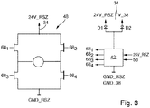
- FIG. 3 shows in a schematic partial representation of another exemplary embodiment of a system 10 according to the invention for detecting a wing 12 of a door or the like, wherein only the area of the switching unit 48 is shown.
- the switching unit 48 comprises a can be acted upon by the external control signal 34 H-bridge of electronic switches 68, in particular transistors, in which both the generator for damping the wing movements and for detecting the wing 12 controllable electric motor 18 is arranged.
- the electronic switches 68 of this H-bridge of the switching unit 48 can be controlled via the control and / or regulating unit 42 of the control and / or regulating electronics 22 in such a way that the electric motor 18 (cf. Fig. 2 ) to the generator damping of the wing movements as a generator operable or to determine the wing 12 a supplied by the external electrical energy voltage at the motor terminals 46 can be applied.
- the electronic switches 68 of the H-bridge of the switching unit 48 via the control and / or regulating unit 42 in particular so controlled that at his particular specifiable locking position einskydem wing 12 and adjacent external control signal 34 for detecting the wing 12 to the motor terminals 46 of Electric motor 18 (see also again Fig. 2 ) a voltage supplied by the external electric power is applied.
- the electronic Switch 68 of the H-bridge can be controlled via the control and / or regulating unit 42 for detecting the wing 12, in particular depending on the direction of the moment of the mechanical energy accumulator 16.
- control and / or regulating unit 42 of the regeneratively damped drive 14 or door closer also assumes the determination of the wing 12 (see also again Fig. 2 ). It is in the Fig. 3 only the corresponding modified section of the embodiment according to Fig. 2 shown.
- Each of the electronic switches 68 1 to 68 4 can be controlled separately via the control and / or regulating unit 42.
- the wing 12 is not in the locked position, which can be signaled via the position sensor 56, or provides the external device 24 or smoke control center (see also again Fig. 2 ) not the required voltage of, for example 24 V (signal "24V-RSZ"), this recognizes the control and / or regulating unit 42 based on these two signals.
- the control and / or regulating unit 42 opens the electronic switches 68 1 and 68 2 and attenuates the closing movement of the wing 12, for example, by a pulse-width-modulated short circuit of the electric motor 18 via the electronic switches 68 3 and 68 4 .
- the control and / or regulating unit 42 is either made of the electric motor 38 operating as a generator (cf. Fig. 2 ) or supplied by the external device 24 or smoke control center voltage 24V-RSZ supplied.
- the control and / or regulating unit 42 which then activates the wing 12 by activating the two electronic switches 68 1 and 68 4 and 68 2 and 68 3 , depending on the direction of the spring torque against the force of the spring of the mechanical energy accumulator 16 holds or notes.
- pulse-width modulated control of the two transistors and an evaluation of the output signal of the position sensor 56 is as in the embodiment according to Fig. 2 achieved an optimization of energy consumption.
- the supply of the control and / or regulating unit 42 can now take place from the external device 24 or smoke control unit (24V-RSZ).
- this embodiment according to Fig. 3 at least essentially the same structure as that of the Fig. 2 have.
- Fig. 4 shows a schematic representation of an exemplary embodiment of a system 10 according to the invention for emergency opening of a wing 12 of a door or the like, in which the control and / or regulating electronics 22 of the drive 14 or door closer comprises a switching unit 48 which between a first switching state in which the Motor terminals 46 of the electric motor 18 are connected to the regenerative damping of the wing movements with the damping circuit 40, and a second switching state is switchable, wherein the motor terminals 46 of the electric motor 18 for electromotive emergency opening of the wing 12 to a supplied by the external electrical power voltage 50 from a external device 24 are applied, which is here, for example, a smoke and heat exhaust center.
- a switching unit 48 which between a first switching state in which the Motor terminals 46 of the electric motor 18 are connected to the regenerative damping of the wing movements with the damping circuit 40, and a second switching state is switchable, wherein the motor terminals 46 of the electric motor 18 for electromotive emergency opening of the wing 12 to
- the switching unit 48 comprises an H-bridge, which can be acted upon by the external control signal, consisting of electronic switches 68, in particular transistors, in which the electric motor 18, which is controllable both for regenerative damping of the wing movements and for the electromotive emergency opening of the wing 12, is arranged.
- the electronic switches 18 are so controllable via the control and / or regulating unit 42 of the control and / or regulating electronics 22 in the present case that the electric motor 18 for regenerative damping of the wing movements as a generator operable or for electromotive emergency opening of the wing 12 a through the external electrical energy supplied voltage at the motor terminals 46 can be applied.
- the control of the electronic switch 68 of the H-bridge for emergency opening of the wing 12 can be effected in particular in dependence on the direction of rotation of the wing 12.
- the external output signal 34 formed by the output signal of the external device 24 and RWA (smoke and heat exhaust) center of the H-bridge comprehensive switching unit 48 via a rectifier or diode bridge 70 are supplied.
- the control and / or regulating unit 42 controls the H-bridge of the switching unit 48 for regenerative damping of the drive 14 or door closer.
- the control and / or regulating unit 42 blocks the electronic switches 68 1 and 68 2 of the H-bridge containing the electric motor 18 and thus damps the closing of the wing 12, for example by a pulse-width-modulated short circuit of the electronic switches 68 1 and 68 4 .
- the control and / or regulating unit 42 is now supplied from the engine line (24V-RWA).
- the control and / or regulating unit 42 takes the command "open" from the signals R1 and R2 and opens the wing 12 with regenerative damping by the electric motor 18 by a corresponding control of the electronic switches 68 1 and 68 4 and 68 2, for example pulse-width modulated and in response to the output signal of the position sensor 56 in response to the direction of rotation of the blade 12 is controlled accordingly.
- the control and / or regulating unit 42 energizes a bistable locking unit 72 which, for example, comprises a bistable brake unit for acting on the motor shaft 20 of the electric motor 18 can.
- the vane 12 now remains in the open position against the force of the mechanical energy accumulator 16 in the present case, for example a spring, without the external device 24 or RWA center having to supply energy.
- the external device 24 or RWA center wants to close the wing 12.
- the control and / or regulating unit 42 is now also supplied with electrical energy from the external device 24 or RWA control center, which takes place via the diode or rectifier bridge 70.
- the control and / or regulating unit 42 unlocks the bistable locking unit 72 via a short pulse, whereupon the blade 12 is regeneratively damped as after a manual opening, for example by locking the electronic switches 68 1 and 68 2 and via the electronic switches 68 3 and 68 4 a particular pulse width modulated short circuit of the motor terminals 46 of the electric motor 18 is generated.
- the aforementioned locking position can be predetermined, for example, by the maximum open position of the wing 12 or variably adjustable as a parameter via a commissioning unit or the like.
- wing 12 can be fixed at least above a predefinable opening angle upon reaching a respective opening angle.
- the determination of the wing 12 can be solvable in a respective locking position by manual operation of the wing 12.
- the force required for the manual triggering of the determination can be parameterizable, for example.
- the respective drive 14 may also comprise a safety sensor system that can be supplied in particular via the external device 24 with external electrical energy.
- a safety sensor system may in particular comprise at least one sensor for monitoring the area in the closing direction in front of the wing 12 on the opposite side of the band and / or at least one sensor for monitoring the area in the opening direction in front of the wing 12 on the band side.
- both wings 12 can each have at least one for determining the wing 12 in a particular predefinable Be assigned parking position and / or the electric motor emergency opening of the wing 12 controllable electric motor 18.
- external power can be supplied to at least the active leaf, in particular via the external device 24.
Abstract
Eine Anlage zur Feststellung und/oder Notöffnung eines Flügels einer Tür, eines Fensters oder dergleichen umfasst einen Antrieb mit wenigstens einem mechanischen Energiespeicher, der durch eine Öffnungsbewegung des Flügels aufgeladen und mit einer Schließbewegung des Flügels entladen wird, wenigstens einem Elektromotor, dessen Motorwelle mit dem Flügel in Wirkverbindung steht, und einer Steuer- und/oder Regelelektronik zur Ansteuerung des Elektromotors. Der Elektromotor ist über die Steuer- und/oder Regelelektronik sowohl zur generatorischen Dämpfung der Flügelbewegungen als auch entgegen der Kraft des mechanischen Speichers zur Feststellung des Flügels und/oder zur elektromotorischen Notöffnung des Flügels ansteuerbar, indem der Elektromotor zur Feststellung und/oder Notöffnung des Flügels zusätzlich mit externer elektrischer Energie aus einer externen Einrichtung wie insbesondere einer Rauchschaltzentrale, einer Rauch- und Wärmeabzugszentrale oder dergleichen versorgbar ist.A system for detecting and / or emergency opening a wing of a door, a window or the like comprises a drive with at least one mechanical energy storage, which is charged by an opening movement of the wing and discharged with a closing movement of the wing, at least one electric motor whose motor shaft with the Wing is operatively connected, and a control and / or regulating electronics for controlling the electric motor. The electric motor can be controlled via the control and / or regulating electronics for both the generator damping of the wing movements and against the force of the mechanical memory for detecting the wing and / or the electromotive emergency opening of the wing by the electric motor for detecting and / or emergency opening of the wing in addition with external electrical energy from an external device such as in particular a smoke control center, a smoke and heat exhaust control center or the like can be supplied.
Description
Die Erfindung betrifft eine Anlage zur Feststellung und/oder Notöffnung eines Flügels einer Tür, eines Fensters oder dergleichen, mit einem Antrieb mit wenigstens einem mechanischen Energiespeicher, der durch eine Öffnungsbewegung des Flügels aufgeladen und mit einer Schließbewegung des Flügels entladen wird, wenigstens einem Elektromotor, dessen Motorwelle mit dem Flügel in Wirkverbindung steht, und einer Steuer- und/oder Regelelektronik, über die der Elektromotor zur generatorischen Dämpfung der Flügelbewegungen ansteuerbar ist.The invention relates to a system for detecting and / or emergency opening a wing of a door, a window or the like, with a drive with at least one mechanical energy storage, which is charged by an opening movement of the wing and discharged with a closing movement of the wing, at least one electric motor, the motor shaft is in operative connection with the wing, and a control and / or regulating electronics, via which the electric motor for regenerative damping of the wing movements can be controlled.
Antriebe oder Türschließer für bewegliche Türflügel mit einem mechanischen Energiespeicher und hydraulischer Dämpfung sind allgemein bekannt. Beim manuellen Öffnen des Türflügels wird der mechanische Energiespeicher mit potentieller Energie aufgeladen, welche den losgelassenen Türflügel wieder schließt. Der mechanische Energiespeicher kann beispielsweise eine Feder umfassen, die durch das manuelle Öffnen des Türflügels gespannt wird und sich mit dem Schließen des Türflügels wieder entspannt.Actuators or door closers for movable door leaves with a mechanical energy storage and hydraulic damping are well known. When the door leaf is opened manually, the mechanical energy store is charged with potential energy, which closes the released door leaf again. The mechanical energy storage may, for example, comprise a spring, which is tensioned by the manual opening of the door leaf and relaxes again with the closing of the door leaf.
Es sind auch bereits generatorisch gedämpfte Türschließer mit wenigstens einem als Generator betriebenen Elektromotor bekannt, dessen Motorwelle mit dem Flügel in Wirkverbindung steht und dessen Motorklemmen zur Dämpfung der Flügelbewegungen über eine Steuer- oder Regelelektronik kurzgeschlossen werden können. Außer einem Gehäuse und einem Beschlag zur Verbindung zwischen Getriebe und Türflügel umfasst auch ein solcher generatorisch gedämpfter Türschließer in der Regel wieder eine als mechanischer Speicher dienende Feder.There are already known generator damped door closer with at least one operated as a generator electric motor whose motor shaft is operatively connected to the wing and the motor terminals can be shorted to attenuate the wing movements via a control or control electronics. In addition to a housing and a fitting for connection between the gearbox and the door, such a regenerated damped door closer usually also includes a spring acting as a mechanical reservoir.
Beim manuellen Öffnen der Tür wird die Feder gespannt, wodurch potentielle Energie in die Feder geladen wird. Gleichzeitig wird mit dem Öffnen der Tür das dem Elektromotor üblicherweise zugeordnete Getriebe gedreht. Bei dem wenigstens einen Elektromotor handelt es sich in der Regel um einen bürstenbehafteten oder bürstenlosen magnetisch erregten Gleichstrommotor. Zum einen wird damit elektrische Energie für die Steuer- oder Regelelektronik aus der Flügelbewegung erzeugt. Zum anderen kann über die Steuer- oder Regelelektronik die Bewegung des Türflügels durch Kurzschließen der Motorwicklungen gedämpft werden. Insbesondere kann über die Steuer- oder Regelelektronik nach dem Loslassen des Türflügels die durch die sich entspannende Feder verursachte Schließbewegung des Türflügels gesteuert bzw. geregelt gedämpft werden, was beispielsweise über eine Pulsweitenmodulation des Kurzschlusses in Abhängigkeit von der aktuellen Position bzw. der aktuellen Geschwindigkeit des Türflügels erfolgen kann.When the door is opened manually, the spring is tensioned, which loads potential energy into the spring. At the same time with the opening of the door, the electric motor usually associated gear is rotated. The at least one electric motor is usually a brush-type one or brushless magnetically excited DC motor. On the one hand, this generates electrical energy for the control electronics from the wing movement. On the other hand, the movement of the door leaf can be damped by short-circuiting the motor windings on the control or regulating electronics. In particular, can be controlled or damped controlled by the relaxing spring caused closing movement of the door via the control or regulating electronics after releasing the door, which for example via a pulse width modulation of the short circuit in dependence on the current position or the current speed of the door leaf can be done.
Ein solcher generatorisch gedämpfter Türflügel arbeitet in der Regel wie ein bekannter hydraulisch gedämpfter Türschließer autark, d.h. er benötigt keine externe elektrische Energiequelle, weder über das Netz noch über einen Akkumulator.Such a regenerated damped door usually operates as a known hydraulically damped door closer self-sufficient, i. it does not require an external source of electrical power, either through the mains or through an accumulator.
Eine Feststellvorrichtung muss nach den derzeitigen Richtlinien mit elektrischer Energie nach dem Arbeitsstromprinzip die selbstschließende Eigenschaft des Türschließers aufheben. Im beispielsweise durch einen Brandmelder ausgelösten Alarmfall schaltet die Auslösevorrichtung einer Brandschaltzentrale die elektrische Energie ab, wodurch die Feststellvorrichtung auslöst und der Türflügel durch die den mechanischen Speicher bildende Feder geschlossen wird. Liegt an der Feststellvorrichtung keine elektrische Energie an, schließt die Tür nach manueller Öffnung. Das Schließen der Tür erfolgt dabei kontrolliert, d.h. gedämpft.A locking device must cancel the self-closing feature of the door closer according to the current electrical current guidelines. In the case of an alarm triggered, for example, by a fire alarm, the triggering device of a fire switching center switches off the electrical energy, whereby the locking device triggers and the door leaf is closed by the spring forming the mechanical memory. If there is no electrical energy at the locking device, the door closes after manual opening. The closing of the door is controlled, i. E. attenuated.
Ist an einer Zulufttür ein Türschließer montiert, so arbeitet dieser im Normalfall wie ein herkömmlicher Türschließer. Im Alarmfall wie bei einem Brand oder auftretendem Rauch liefert eine Rauch-Wärme-Abzugsanlage elektrische Energie, wodurch die Zulufttür entgegen der Kraft der Feder des Türschließers geöffnet wird. Das betreffende Gebäude wird hiermit dadurch mit den entsprechenden Abluftfenstern entraucht.If a door closer is installed on a supply air door, it usually works like a conventional door closer. In the event of an alarm, such as a fire or smoke occurring, a smoke-heat extraction system provides electrical energy, which opens the air supply door against the force of the spring of the door closer. The relevant building is hereby thereby used with the corresponding exhaust windows.
Dazu wird bisher zusätzlich zum hydraulischen Türschließer ein Zuluftöffner montiert, der in der Regel eine Motor-Getriebe-Einheit umfasst, die über einen Hebel oder eine Rolle den Türflügel öffnet. Zuluftöffner und Türschließer müssen dabei insoweit entkoppelt sein, dass auch bei geschlossenem Zuluftöffner der Türflügel noch manuell geöffnet werden kann. Im Brandfall liefert die Rauch- und Wärmeabzugszentrale elektrische Energie, wodurch der Zuluftöffner den Türflügel öffnet und diesen offenhält, solange das Warnsignal der Rauch- und Wärmeabzugszentrale bzw. die entsprechende elektrische Energie ansteht.For this purpose, a Zuluftöffner is previously mounted in addition to the hydraulic door closer, which usually includes a motor-gear unit that opens the door leaf via a lever or a roller. Supply air opener and door closer must be decoupled to the extent that the door leaf can still be opened manually even when the supply air opener is closed. In the event of a fire, the smoke and heat exhaust ventilation unit supplies electrical energy, which opens the door opener and keeps it open, as long as the smoke alarm and heat exhaust system alarm signal or the corresponding electrical energy is present.
Die bisher bekannten generatorisch gedämpften Türschließer oder Antriebe können weder den Türflügel gegen die Kraft des mechanischen Speichers offenhalten, d.h. den Türflügel feststellen, noch den Türflügel gegen die Kraft des mechanischen Speichers öffnen, d.h. die Zuluftfunktion für einen Rauch- und Wärmeabzug erfüllen.The previously known regeneratively damped door closers or actuators can not keep the door open against the force of the mechanical accumulator, i. lock the door, still open the door against the force of the mechanical storage, i. fulfill the supply air function for a smoke and heat exhaust.
Der Erfindung liegt die Aufgabe zugrunde, eine Anlage zur Feststellung und/oder Notöffnung eines Flügels einer Tür, eines Fensters oder dergleichen anzugeben, bei der die beiden Funktionen Feststellung und Notöffnung auf möglichst einfache und entsprechend kostengünstige Weise realisiert sind.The invention has for its object to provide a system for detecting and / or emergency opening a wing of a door, a window or the like, in which the two functions detection and emergency opening are realized in the simplest possible and correspondingly cost-effective manner.
Erfindungsgemäß wird diese Aufgabe durch eine Feststell- und/oder Notöffnungsanlage mit den Merkmalen des Anspruchs 1 gelöst. Bevorzugte Ausführungsformen der erfindungsgemäßen Anlage ergeben sich aus den Unteransprüchen, der vorliegenden Beschreibung sowie der Zeichnung.According to the invention this object is achieved by a locking and / or emergency opening system with the features of claim 1. Preferred embodiments of the system according to the invention will become apparent from the dependent claims, the present description and the drawings.
Die erfindungsgemäße Anlage zur Feststellung und/oder Notöffnung eines Flügels einer Tür, eines Fensters oder dergleichen umfasst einen Antrieb oder Türschließer mit wenigstens einem mechanischen Energiespeicher, der durch eine Öffnungsbewegung des Flügels aufgeladen und mit einer Schließbewegung des Flügels entladen wird, wenigstens einem Elektromotor, dessen Motorwelle mit dem Flügel in Wirkverbindung steht, und einer Steuer- und/oder Regelelektronik zur Ansteuerung des Elektromotors. Dabei ist der Elektromotor über die Steuer- und/oder Regelelektronik sowohl zur generatorischen Dämpfung der Flügelbewegungen als auch entgegen der Kraft des mechanischen Speichers zur Feststellung des Flügels und/oder zur elektromotorischen Notöffnung des Flügels ansteuerbar, indem der Elektromotor zur Feststellung und/oder Notöffnung des Flügels zusätzlich mit externer elektrischer Energie aus einer externen Einrichtung wie insbesondere einer Rauchschaltzentrale, einer Rauch- und Wärmeabzugszentrale oder dergleichen versorgbar ist.The inventive system for detecting and / or emergency opening a wing of a door, a window or the like comprises a drive or door closer with at least one mechanical energy storage, which is charged by an opening movement of the wing and discharged with a closing movement of the wing, at least one electric motor whose Motor shaft with the Wing is operatively connected, and a control and / or regulating electronics for controlling the electric motor. In this case, the electric motor via the control and / or control electronics for both the dynamic damping of the wing movements and against the force of the mechanical memory for detecting the wing and / or the electromotive emergency opening of the wing controlled by the electric motor for detecting and / or emergency opening of the Wing is additionally supplied with external electrical energy from an external device such as in particular a smoke control center, a smoke and heat exhaust control center or the like.
Aufgrund dieser Ausbildung kann der wenigstens eine zur Dämpfung der Flügelbewegungen als Generator betriebene Elektromotor eines generatorisch gedämpften Antriebs bzw. Türschließers auch zur Feststellung und Notöffnung des Flügels herangezogen werden, womit diese beiden Funktionen auf einfache Weise und entsprechend kostengünstig realisiert sind. So kann der wenigstens eine Elektromotor zum Offenhalten des Flügels beispielsweise aus einer Auslösevorrichtung und zum Öffnen der Tür im Alarmfall beispielsweise aus einer Rauch- und Wärmeabzugszentrale mit elektrischer Energie versorgt werden. Dabei kann die elektrische Energie aus dem Netz oder einem elektrischen Energiespeicher geliefert werden.Due to this design, the at least one operated for damping the wing movements as a generator electric motor of a regenerative damped drive or door closer can also be used for detecting and emergency opening of the wing, so these two functions are realized in a simple manner and correspondingly inexpensive. Thus, the at least one electric motor for keeping the wing open, for example, from a triggering device and to open the door in case of alarm, for example, from a smoke and heat exhaust control center are supplied with electrical energy. In this case, the electrical energy can be supplied from the network or an electrical energy storage.
Vorteilhafterweise ist der Elektromotor über die Steuer- und/oder Regelelektronik in Abhängigkeit von einem durch ein Ausgangssignal der externen Einrichtung gebildeten externen Steuersignal zur Feststellung und/oder Notöffnung des Flügels ansteuerbar. Dabei ist der Elektromotor zur Feststellung und/oder zur elektromotorischen Notöffnung des Flügels vorteilhafterweise über das externe Steuersignal mit der externen elektrischen Energie versorgbar. Über das betreffende externe Steuersignal wird somit nicht nur die jeweilige Feststell- oder Notöffnungsfunktion ausgelöst. In diesem Fall liefert dieses externe Steuersignal gleichzeitig auch die für den Elektromotor erforderliche zusätzliche elektrische Energie.Advantageously, the electric motor can be controlled via the control and / or regulating electronics as a function of an external control signal formed by an output signal of the external device for detecting and / or emergency opening of the blade. In this case, the electric motor for detecting and / or the electromotive emergency opening of the wing advantageously over the external control signal with the external electrical energy can be supplied. Thus, not only the respective locking or emergency opening function is triggered via the relevant external control signal. In this case, this external control signal also supplies the additional electrical energy required for the electric motor.
Der Antrieb umfasst zweckmäßigerweise einen elektrischen Energiespeicher, der über einen über seine Motorwelle mit dem Flügel in Wirkverbindung stehenden, als Generator betreibbaren Elektromotor aufladbar und über den die Steuer- und/oder Regelelektronik mit Energie versorgbar ist. Dabei kann es sich bei dem zur Aufladung des elektrischen Energiespeichers vorgesehenen, als Generator betreibbaren Elektromotor um einen auch zur Dämpfung der Flügelbewegungen und zur Feststellung und/oder Notöffnung vorgesehenen Elektromotor oder um einen getrennten Motor handeln. Grundsätzlich sind also insbesondere auch solche Ausführungen denkbar, bei denen der elektrische Energiespeicher durch den wenigstens einen sowohl zur generatorischen Dämpfung der Flügelbewegungen als auch zur Feststellung und/oder Notöffnung vorgesehenen Elektromotor aufgeladen wird.The drive expediently comprises an electrical energy store which can be charged via an electric motor which is operatively connected to the vane via its motor shaft and which can be operated as a generator and via which the control and / or regulating electronics can be supplied with energy. In this case, it may be in the provided for charging the electrical energy storage, operable as a generator electric motor to a provided for damping the wing movements and to determine and / or emergency opening electric motor or a separate motor. In principle, therefore, in particular those embodiments are conceivable in which the electrical energy storage is charged by the at least one intended both for the regenerative damping of the wing movements as well as for the detection and / or emergency opening electric motor.
Die Steuer- und/oder Regelelektronik umfasst bevorzugt einen Dämpfungskreis mit wenigstens einem über eine Steuer- und/oder Regeleinheit ansteuerbaren Schaltelement, über das die Motorklemmen des an den Dämpfungsstromkreis angeschlossenen Elektromotors zur generatorischen Dämpfung der Flügelbewegungen kurzschließbar sind.The control and / or regulating electronics preferably comprises a damping circuit with at least one controllable via a control and / or regulating unit switching element via which the motor terminals of the electric motor connected to the damping circuit for regenerative damping of the wing movements are kurzschließbar.
Bevorzugt umfasst die Steuer- und/oder Regelelektronik eine Umschalteinheit, die zwischen einem ersten Schaltzustand, bei dem die Motorklemmen des Elektromotors zur generatorischen Dämpfung der Flügelbewegungen mit dem Dämpfungsstromkreis verbunden sind, und einem zweiten Schaltzustand umschaltbar ist, bei dem die Motorklemmen des Elektromotors zur Feststellung des Flügels bei einer insbesondere vorgebbaren Feststellposition und/oder zur elektromotorischen Notöffnung des Flügels an eine durch die externe elektrische Energie gelieferte Spannung angelegt sind. Die Feststellposition kann beispielsweise der maximalen Öffnungsposition des Flügels entsprechen oder auch variabel vorgebbar sein. Die Umschalteinheit kann beispielsweise in dem Dämpfungsstromkreis integriert sein und diesen zur Feststellung oder Notöffnung des Flügels unterbrechen.Preferably, the control and / or regulating electronics comprises a switching unit, which is switchable between a first switching state, in which the motor terminals of the electric motor for regenerative damping of the wing movements with the damping circuit, and a second switching state, wherein the motor terminals of the electric motor for detection of the wing at a particular specifiable locking position and / or the electromotive emergency opening of the wing are applied to a voltage supplied by the external electrical energy voltage. The locking position, for example, the maximum Correspond to the opening position of the wing or be specified variably. The switching unit may for example be integrated in the damping circuit and interrupt it for detecting or emergency opening of the wing.
Von Vorteil ist insbesondere, wenn die Umschalteinheit zur Feststellung des Flügels ihren zweiten Schaltzustand annimmt, wenn der Flügel die insbesondere vorgebbare Feststellposition einnimmt und das externe Steuersignal an der Steuer- und/oder Regelelektronik anliegt.It is particularly advantageous if the switching unit for determining the wing assumes its second switching state, when the wing occupies the particular predeterminable locking position and the external control signal is applied to the control and / or regulating electronics.
Gemäß einer bevorzugten praktischen Ausführungsform der erfindungsgemäßen Anlage umfasst die Umschalteinheit ein Relais, über das im unbestromten Zustand die Motorklemmen des Elektromotors zur generatorischen Dämpfung der Flügelbewegungen mit dem Dämpfungsstromkreis verbindbar und über das im bestromten Zustand die Klemmen des Elektromotors zur Feststellung und/oder zur elektromotorischen Notöffnung des Flügels an eine durch die externe elektrische Energie gelieferte Spannung anlegbar sind.According to a preferred practical embodiment of the system according to the invention, the switching unit comprises a relay, connected in the de-energized state, the motor terminals of the electric motor for regenerative damping of the wing movements with the damping circuit and the current in the energized state, the terminals of the electric motor for detection and / or electromotive emergency opening the wing can be applied to a voltage supplied by the external electrical energy voltage.
Gemäß einer zweckmäßigen praktischen Ausführungsform der erfindungsgemäßen Anlage ist das externe Steuersignal der Umschalteinheit über einen Positionsschalter zuführbar, der bei die insbesondere vorgebbare Feststellposition einnehmendem Flügel schließbar ist. Von Vorteil ist insbesondere auch, wenn zur Erzeugung der zur Feststellung und/oder zur elektromotorischen Notöffnung des Flügels an den Elektromotor anzulegenden Spannung eine Pegelanpassungseinheit vorgesehen ist, über die der Pegel des externen Steuersignals an den zur Spannungsversorgung des Elektromotors erforderlichen Pegel anpassbar ist.According to an expedient practical embodiment of the system according to the invention, the external control signal of the switching unit via a position switch can be fed, which is closed at the particular specifiable locking position einnehmendem wing. It is also particularly advantageous if a level adjusting unit is provided for generating the voltage to be applied to the electric motor for detecting and / or electromotive emergency opening of the vane, by means of which the level of the external control signal can be adapted to the level required for the voltage supply of the electric motor.
Eine alternative, insbesondere hinsichtlich einer Energieoptimierung vorteilhafte Ausführungsform der erfindungsgemäßen Anlage zeichnet sich dadurch aus, dass das externe Steuersignal der Umschalteinheit über eine Steuer- und/oder Regeleinheit der Steuer- und/oder Regelelektronik in Abhängigkeit vom Ausgangssignal eines die insbesondere vorgebbare Feststellposition des Flügels erfassenden Positionsgebers zuführbar ist. Dabei ist insbesondere auch von Vorteil, wenn zur Erzeugung der zur Feststellung und zur elektromotorischen Notöffnung des Flügels an den Elektromotor anzulegenden Spannung das externe Steuersignal dem Elektromotor zur Pegelanpassung über eine solche Steuer- und/oder Regeleinheit der Steuer- und/oder Regelelektronik zuführbar ist.An alternative embodiment of the system according to the invention, which is advantageous in particular with regard to energy optimization, is characterized in that the external control signal of the switching unit via a control and / or regulating unit of the control and / or regulating electronics as a function of the output signal one of the particular specifiable locking position of the wing detecting position sensor can be fed. In this case, it is particularly advantageous if the external control signal can be supplied to the electric motor for adjusting the level via such a control and / or regulating unit of the control and / or regulating electronics for generating the voltage to be applied to the electric motor for detection and electromotive emergency opening of the blade.
Gemäß einer weiteren bevorzugten praktischen Ausführungsform der erfindungsgemäßen Anlage umfasst die Umschalteinheit eine durch das externe Steuersignal beaufschlagbare H-Brücke aus elektronischen Schaltern wie insbesondere Transistoren, in der der sowohl zur generatorischen Dämpfung der Flügelbewegungen als auch zur Feststellung des Flügels und/oder zur elektromotorischen Notöffnung des Flügels ansteuerbare Elektromotor angeordnet ist und deren elektronische Schalter über eine Steuer- und/oder Regeleinheit der Steuer- und/oder Regelelektronik so ansteuerbar sind, dass der Elektromotor zur generatorischen Dämpfung der Flügelbewegungen als Generator betreibbar bzw. zur Feststellung und/oder zur elektromotorischen Notöffnung des Flügels eine durch die externe elektrische Energie gelieferte Spannung an dessen Motorklemmen anlegbar ist.According to a further preferred practical embodiment of the system according to the invention, the switching unit comprises a can be acted upon by the external control signal H-bridge of electronic switches such as transistors, in which both the generator damping of the wing movements as well as to determine the wing and / or the electromotive emergency opening of the Is arranged vane controllable electric motor and the electronic switch via a control and / or regulating unit of the control and / or control electronics are controlled so that the electric motor for regenerative damping of the wing movements as a generator operable or for detecting and / or electromotive emergency opening of Wing supplied by the external electrical power voltage at the motor terminals can be applied.
Dabei ist insbesondere von Vorteil, wenn die elektronischen Schalter der H-Brücke über die Steuer- und/oder Regeleinheit so ansteuerbar sind, dass bei seine insbesondere vorgebbare Feststellposition einnehmendem Flügel und anliegendem externem Steuersignal zur Feststellung und/oder zur elektromotorischen Notöffnung des Flügels an die Motorklemmen des Elektromotors eine durch die externe elektrische Energie gelieferte Spannung angelegt wird.It is particularly advantageous if the electronic switches of the H-bridge on the control and / or regulating unit are controlled so that at his particular specifiable locking position einnehmendem wing and adjoining external control signal for detecting and / or electromotive emergency opening of the wing to the Motor terminals of the electric motor is supplied by the external electrical energy supplied voltage.
Die elektronischen Schalter der H-Brücke sind über die Steuer- und/oder Regeleinheit zur Feststellung des Flügels bevorzugt in Abhängigkeit von der Richtung des Moments des mechanischen Energiespeichers und/oder zur Notöffnung des Flügels in Abhängigkeit von der Drehrichtung des Flügels ansteuerbar.The electronic switches of the H-bridge can be controlled via the control and / or regulating unit for determining the wing, preferably depending on the direction of the moment of the mechanical energy storage and / or emergency opening of the wing depending on the direction of rotation of the wing.
Von Vorteil ist insbesondere auch, wenn die Umschalteinheit über die zugeordnete Steuer- und/oder Regeleinheit der Steuer- und/oder Regelelektronik zur Feststellung des Flügels so ansteuerbar ist, dass die dem Elektromotor zugeführte elektrische Energie gerade ausreicht, um die potentielle Energie des mechanischen Energiespeichers zu kompensieren.It is also particularly advantageous if the switching unit can be controlled via the associated control and / or regulating unit of the control and / or regulating electronics for detecting the blade so that the electrical energy supplied to the electric motor is just sufficient to the potential energy of the mechanical energy storage to compensate.
Gemäß einer weiteren praktischen Ausführungsform der erfindungsgemäßen Anlage ist über die zur Ansteuerung der Umschalteinheit vorgesehene Steuer- und/oder Regeleinheit zur Feststellung des Flügels in der insbesondere vorgebbaren Feststellposition und/oder zum Offenhalten des Flügels nach erfolgter Notöffnung eine bistabile Feststelleinheit ansteuerbar. Dabei ist insbesondere von Vorteil, wenn die bistabile Feststelleinheit eine bistabile Bremseinheit zur Beaufschlagung der Motorwelle des Elektromotors umfasst.According to a further practical embodiment of the system according to the invention, a bistable locking unit can be actuated via the control and / or regulating unit provided for controlling the switching unit to determine the wing in the particular predefinable locking position and / or to keep the wing open. It is particularly advantageous if the bistable locking unit comprises a bistable brake unit for acting on the motor shaft of the electric motor.
Die bistabile Feststelleinheit ist bevorzugt bei einem Alarm wie insbesondere im Brandfall über die Steuer- und/oder Regeleinheit entriegelbar.The bistable locking unit is preferably unlocked in an alarm as in particular in case of fire on the control and / or regulating unit.
Die Feststellposition kann der maximalen Offenstellung des Flügels entsprechen oder vorteilhafterweise auch beispielsweise als Parameter über eine Inbetriebnahmeeinheit oder dergleichen variabel einstellbar sein.The locking position may correspond to the maximum open position of the wing or advantageously also be variably adjustable, for example, as a parameter via a commissioning unit or the like.
Gemäß einer weiteren vorteilhaften Ausführungsform ist der Flügel zumindest oberhalb eines vorgebbaren Öffnungswinkels bei Erreichen eines jeweiligen Öffnungswinkels feststellbar. Der Flügel wird also nach einer jeweiligen Öffnungsbewegung festgestellt, sobald er angehalten wird.According to a further advantageous embodiment, the wing is detectable at least above a predefinable opening angle upon reaching a respective opening angle. The wing is thus detected after a respective opening movement, as soon as it is stopped.
Zweckmäßigerweise ist die Feststellung des Flügels in einer jeweiligen Feststellposition durch manuelle Betätigung des Flügels lösbar. Dabei kann die zum manuellen Auslösen der Feststellung benötigte Kraft parametrisierbar sein. Von Vorteil ist insbesondere auch, wenn bei einem jeweiligen Feststellwinkel, der kleiner ist als der maximale Öffnungswinkel des Flügels, der Feststellwinkel auch überfahrbar ist, so dass der Flügel insbesondere manuell aus der Feststellung gelöst und über die betreffende Feststellposition hinaus geöffnet werden kann.Conveniently, the determination of the wing in a respective locking position by manual operation of the wing is solvable. In this case, the force required for the manual triggering of the determination can be parameterized. Advantageous In particular, even if at a respective locking angle, which is smaller than the maximum opening angle of the wing, the locking angle is also traversable, so that the wing in particular manually released from the determination and can be opened beyond the respective locking position.
Gemäß einer weiteren zweckmäßigen praktischen Ausführungsform der erfindungsgemäßen Anlage umfasst der Antrieb eine insbesondere über die externe Einrichtung mit externer elektrischer Energie versorgbare Sicherheitssensorik. Dabei ist insbesondere von Vorteil, wenn die Sicherheitssensorik wenigstens einen Sensor zur Überwachung des Bereichs in Schließrichtung vor dem Flügel auf der Bandgegenseite und/oder wenigstens einen Sensor zur Überwachung des Bereichs in Öffnungsrichtung vor dem Flügel auf der Bandseite umfasst.According to a further expedient practical embodiment of the system according to the invention, the drive comprises a safety sensor system that can be supplied in particular via the external device with external electrical energy. In this case, it is particularly advantageous if the safety sensor system comprises at least one sensor for monitoring the area in the closing direction in front of the wing on the hinge opposite side and / or at least one sensor for monitoring the area in the opening direction in front of the wing on the hinge side.
Vorteilhafterweise erfolgt ein jeweiliges Auslösen einer Feststellung und/oder die Aktivierung einer jeweiligen Feststellung und/oder die Dämpfung einer jeweiligen Öffnungsbewegung des Flügels über die Steuer- und/oder Regelelektronik in Abhängigkeit von Ausgangssignalen der Sicherheitssensorik.Advantageously, a respective triggering of a determination and / or the activation of a respective determination and / or the damping of a respective opening movement of the wing via the control and / or regulating electronics in response to output signals of the safety sensor.
Gemäß einer weiteren bevorzugten Ausführungsform der erfindungsgemäßen Anlage ist bei einer zweiflügligen Tür mit einem Standflügel und einem Gangflügel insbesondere für eine elektrische Schließfolgeregelung beiden Flügeln jeweils wenigstens ein zur Feststellung des Flügels bei einer insbesondere vorgebbaren Feststellposition und/oder zur elektromotorischen Notöffnung des Flügels ansteuerbarer Elektromotor zugeordnet. Bevorzugt ist zumindest dem Gangflügel insbesondere über die externe Einrichtung externe elektrische Energie zuführbar.According to a further preferred embodiment of the system according to the invention is associated with a two-leaf door with a fixed leaf and a moving leaf in particular for an electric closing sequence control both wings at least one for determining the wing at a particular specifiable locking position and / or the electromotive emergency opening of the wing controllable electric motor. Preferably, at least the active leaf, in particular external electrical energy can be supplied via the external device.
Die Erfindung wird im Folgenden anhand von Ausführungsbeispielen unter Bezugnahme auf die Zeichnung näher erläutert; in dieser zeigen:
- Fig. 1
- eine schematische Darstellung einer beispielhaften Ausführungsform einer erfindungsgemäßen Anlage zur Feststellung eines Flügels einer Tür oder dergleichen mit einem generatorisch gedämpften Antrieb oder Türschließer, der mit einer ein Relais umfassenden Umschalteinheit versehen ist,
- Fig. 2
- eine schematische Darstellung einer weiteren beispielhaften Ausführungsform einer erfindungsgemäßen Anlage zur Feststellung eines Flügels einer Tür oder dergleichen mit einem ein Relais umfassenden generatorisch gedämpften Antrieb oder Türschließer,
- Fig. 3
- eine schematische Teildarstellung einer beispielhaften Ausführungsform einer erfindungsgemäßen Anlage zur Feststellung eines Flügels einer Tür oder dergleichen mit einem generatorisch gedämpften Antrieb oder Türschließer, der mit einer eine H-Brücke aus elektronischen Schaltern umfassenden Umschalteinheit versehen ist, und
- Fig. 4
- eine schematische Darstellung einer beispielhaften Ausführungsform einer erfindungsgemäßen Anlage zur Notöffnung eines Flügels einer Tür oder dergleichen mit einem eine H-Brücke aus elektronischen Schaltern umfassenden generatorisch gedämpften Antrieb oder Türschließer.
- Fig. 1
- a schematic representation of an exemplary embodiment of a system according to the invention for detecting a wing of a door or the like with a regenerated damped drive or door closer, which is provided with a switch comprising a relay switching unit,
- Fig. 2
- a schematic representation of another exemplary embodiment of a system according to the invention for detecting a wing of a door or the like with a relay comprising a regeneratively damped drive or door closer,
- Fig. 3
- a schematic partial view of an exemplary embodiment of a system according to the invention for detecting a wing of a door or the like with a regeneratively damped drive or door closer, which is provided with a H-bridge comprising electronic switches switching unit, and
- Fig. 4
- a schematic representation of an exemplary embodiment of a system according to the invention for emergency opening a wing of a door or the like with a H-bridge of electronic switches comprehensive generator damped drive or door closer.
Die Feststellanlage 10 umfasst einen Antrieb 14, der hier beispielsweise als Türschließer ausgeführt ist. Der Antrieb 14 umfasst einen insbesondere eine Feder umfassenden mechanischen Speicher 16, der durch eine Öffnungsbewegung des Flügels 12 aufgeladen und mit einer Schließbewegung des Flügels 12 entladen wird, einen Elektromotor 18, dessen Motorwelle 20 mit dem Flügel 12 in Wirkverbindung steht, und eine Steuer- und/oder Regelelektronik 22 zur Ansteuerung des Elektromotors 18.The
Dabei ist der Elektromotor 18 über die Steuer- und/oder Regelelektronik 22 sowohl zur generatorischen Dämpfung der Flügelbewegungen als auch entgegen der Kraft des mechanischen Speichers 16 zur Feststellung des Flügels 12 ansteuerbar, indem der Elektromotor 18 zur Feststellung des Flügels zusätzlich mit einer externen elektrischen Energie aus einer externen Einrichtung 24 versorgbar ist, bei der es sich im vorliegenden Fall beispielsweise um eine Rauchschaltzentrale handelt.In this case, the
Der mechanische Energiespeicher 16 und der Elektromotor 18 können jeweils über ein Getriebe 26 bzw. 28 mit einer Abtriebswelle 30 des Antriebs 14 verbunden sein, die wiederum über einen Beschlag mit dem Flügel 12 gekoppelt ist.The
Der Elektromotor 18 ist über die Steuer- und/oder Regelelektronik 22 in Abhängigkeit von einem durch ein Ausgangssignal der externen Einrichtung 24 gebildeten externen Steuersignal 34 zur Feststellung des Flügels 12 ansteuerbar. Dabei kann der Elektromotor 18 zur Feststellung des Flügels 12 beispielsweise über dieses externe Steuersignal 34 auch mit der externen elektrischen Energie versorgbar sein.The
Zudem kann der Antrieb 14 einen elektrischen Energiespeicher umfassen, der über einen über seine Motorwelle 36 mit dem Flügel 12 in Wirkverbindung stehenden, als Generator betreibbaren Elektromotor 38 aufladbar und über den die Steuer- und/oder Regelelektronik 22 mit Energie versorgbar ist.In addition, the
Die Steuer- und/oder Regelelektronik 22 kann einen Dämpfungskreis 40 mit wenigstens einem über eine Steuer- und/oder Regeleinheit 42 ansteuerbaren Schaltelement 44 umfassen, über das die Motorklemmen 46 des an den Dämpfungsstromkreis 40 angeschlossenen Elektromotors 18 zur generatorischen Dämpfung der Flügelbewegungen kurzschließbar sind.The control and / or regulating
Die Steuer- und/oder Regelelektronik 22 kann eine Umschalteinheit 48 umfassen, die zwischen einem ersten Schaltzustand, bei dem die Motorklemmen 46 des Elektromotors 18 zur generatorischen Dämpfung der Flügelbewegungen mit dem Dämpfungsstromkreis 40 verbunden sind, und einem zweiten Schaltzustand umschaltbar ist, bei dem die Motorklemmen 46 des Elektromotors 18 zur Feststellung des Flügels 12 bei einer insbesondere vorgebbaren Feststellposition an eine durch die externe elektrische Energie gelieferte Spannung 50 angelegt sind. Im vorliegenden Fall nimmt die Umschalteinheit 48 zur Feststellung des Flügels 12 ihren zweiten Schaltzustand an, wenn der Flügel 12 die insbesondere vorgebbare Feststellposition einnimmt und das externe Steuersignal 34 an der Steuer- und/oder Regelelektronik 22 anliegt.The control and / or regulating
Wie aus der
Im vorliegenden Fall ist das externe Steuersignal 34 der Umschalteinheit 48 über einen Positionsschalter 52 zuführbar, der bei die insbesondere vorgebbare Feststellposition einnehmendem Flügel 12 schließbar ist. Zudem ist im vorliegenden Fall zur Erzeugung der zur Feststellung des Flügels 12 an den Elektromotor 18 anzulegenden Spannung 15 eine Pegelanpassungseinheit 54 vorgesehen, über die der Pegel des externen Steuersignals 34 an den zur Spannungsversorgung des Elektromotors 18 erforderlichen Pegel anpassbar ist.In the present case, the
Wie aus der
Die im vorliegenden Fall beispielsweise als Rauchschaltzentrale vorgesehene externe Einrichtung 24 kann beispielsweise ein an das Netz angeschlossenes Netzteil 58, wenigstens einen Brandmelder 60 sowie eine Auslösevorrichtung 62 umfassen. Die externe Einrichtung 24 kann in einem eigenen Gehäuse untergebracht oder im Antrieb bzw. Türschließer 14 integriert sein.The
Im unbestromten Zustand schließt die im vorliegenden Fall ein Relais umfassende Umschalteinheit 48 den Dämpfungsstromkreis 40, d.h. die Motorklemmen 46 des Elektromotors 18 werden an den Dämpfungsstromkreis 40 angeschlossen. Der Antrieb 14 arbeitet somit als generatorisch gedämpfter Antrieb bzw. generatorisch gedämpfter Türschließer. Die Ausgangsspannung der externen Einrichtung 24 bzw. der Rauchschaltzentrale liegt über den Positionsschalter 52 an der Spule des Relais der Umschalteinheit 48 an. Der Positionsschalter 52 schließt seinen Kontakt, sobald der Flügel 12 vollständig geöffnet ist, wobei im vorliegenden Fall beispielsweise die maximale Offenstellung des Flügels 12 die Feststellposition bildet. Grundsätzlich ist jedoch auch eine solche Ausführung denkbar, bei der die Feststellposition variabel vorgebbar ist.In the de-energized state, the switching
Liefert die externe Einrichtung 24 bzw. Rauchschaltzentrale beispielsweise im Fall eines Alarms keine Spannung oder ist der Flügel 12 nicht vollständig geöffnet, so zieht das Relais der Umschalteinheit 48 nicht an. Nach einem jeweiligen Öffnen schließt der Flügel 12 generatorisch gedämpft. Zum Öffnen muss die Feder des mechanischen Speichers 16 gespannt werden.If the
Ist der Flügel 12 in der Feststellposition und liefert die externe Einrichtung 24 bzw. Rauchschaltzentrale Spannung, so zieht das Relais der Umschalteinheit 48 an und verbindet den Elektromotor 18 mit Spannung. Der Flügel 12 wird im vorliegenden Fall gegen die Offenlage gedrückt. Über die Pegelanpassungseinheit 54 wird das Öffnungsmoment des Elektromotors 18 eingestellt.If the
Der Flügel 12 kann bei dieser Ausführungsform auch manuell ausgelöst werden, indem er gegen das Öffnungsmoment des Elektromotors 18 manuell zugedrückt wird. Sobald der Positionsschalter 52 die Verbindung unterbricht, schließt der Flügel generatorisch gedämpft. Dazu kann die Steuer- und/oder Regeleinheit 42 über das beispielsweise einen Feldeffekttransistor umfassende Schaltelement 44 z. B. eine Pulsweitenmodulation des Motorstroms des Elektromotors 18 durchführen, um eine wirksame Dämpfungskraft zur Dämpfung der Flügelbewegungen einzustellen. Die Dämpfung der Flügelbewegungen kann beispielsweise in Abhängigkeit von einer aktuellen Bewegungsrichtung und/oder einer aktuellen Geschwindigkeit und/oder eines aktuellen Öffnungswinkels des Flügels 12 eingestellt werden. Im Übrigen kann die Dämpfung der Flügelbewegungen insbesondere so erfolgen, wie dies in der
Die vorliegende Ausführungsform unterscheidet sich von der
Mittels der Steuer- und/oder Regeleinheit 64 ist es nunmehr beispielsweise möglich, die dem Elektromotor 18 zugeführte elektrische Energie so einzustellen, dass diese gerade ausreicht, die potentielle Energie der Feder des mechanischen Energiespeichers 16 zu kompensieren. Dies kann beispielsweise durch eine Lageregelung auf der Basis des Signals des Positionsgebers 56, durch Lernen der benötigten Halteenergie beim Auslösen und/oder dergleichen erfolgen.By means of the control and / or regulating
Damit ist eine Energie sparende Ausführung der Feststellung realisierbar, die sich zudem mit minimaler Kraft manuell auslösen lässt.Thus, an energy-saving execution of the determination can be realized, which also can be manually triggered with minimal force.
Die externe Einrichtung 24 bzw. Rauchschaltzentrale kann auch hier wieder in einem eigenen Gehäuse angeordnet oder im Gehäuse des Antriebs 14 oder Türschließers montiert sein.The
Auch im Übrigen besitzt diese Ausführungsform zumindest im Wesentlichen wieder den gleichen Aufbau wie die der
Im vorliegenden Fall umfasst die Umschalteinheit 48 eine durch das externe Steuersignal 34 beaufschlagbare H-Brücke aus elektronischen Schaltern 68 wie insbesondere Transistoren, in der der sowohl zur generatorischen Dämpfung der Flügelbewegungen als auch zur Feststellung des Flügels 12 ansteuerbare Elektromotor 18 angeordnet ist. Dabei sind die elektronischen Schalter 68 dieser H-Brücke der Umschalteinheit 48 über die Steuer- und/oder Regeleinheit 42 der Steuer- und/oder Regelelektronik 22 so ansteuerbar, dass der Elektromotor 18 (vgl. auch nochmals
Dabei sind die elektronischen Schalter 68 der H-Brücke der Umschalteinheit 48 über die Steuer- und/oder Regeleinheit 42 insbesondere so ansteuerbar, dass bei seine insbesondere vorgebbare Feststellposition einnehmendem Flügel 12 und anliegendem externem Steuersignal 34 zur Feststellung des Flügels 12 an die Motorklemmen 46 des Elektromotors 18 (vgl. auch nochmals
Im vorliegenden Fall übernimmt somit die Steuer- und/oder Regeleinheit 42 des generatorisch gedämpften Antriebs 14 oder Türschließers auch die Feststellung des Flügels 12 (vgl. auch nochmals
Befindet sich der Flügel 12 nicht in der Feststellposition, was über den Positionsgeber 56 signalisierbar ist, oder liefert die externe Einrichtung 24 bzw. Rauchschaltzentrale (vgl. auch nochmals
Liefert die externe Einrichtung 24 bzw. Rauchschaltzentrale die geforderte Spannung von beispielsweise 24 V und nimmt der Flügel 12 seine Feststellposition ein, so erkennt dies die Steuer- und/oder Regeleinheit 42, die daraufhin den Flügel 12 durch eine Ansteuerung der beiden elektronischen Schalter 681 und 684 bzw. 682 und 683 in Abhängigkeit von der Richtung des Federmoments entgegen der Kraft der Feder des mechanischen Energiespeichers 16 hält bzw. feststellt. Über eine beispielsweise pulsweitenmodulierte Ansteuerung der beiden Transistoren und eine Auswertung des Ausgangssignals des Positionsgebers 56 wird wie bei der Ausführungsform gemäß
Im Übrigen kann diese Ausführungsform gemäß
Die Umschalteinheit 48 umfasst im vorliegenden Fall eine durch das externe Steuersignal 34 beaufschlagbare H-Brücke aus elektronischen Schaltern 68 wie insbesondere Transistoren, in der der sowohl zur generatorischen Dämpfung der Flügelbewegungen als auch zur elektromotorischen Notöffnung des Flügels 12 ansteuerbare Elektromotor 18 angeordnet ist. Die elektronischen Schalter 18 sind über die Steuer- und/oder Regeleinheit 42 der Steuer- und/oder Regelelektronik 22 im vorliegenden Fall so ansteuerbar, dass der Elektromotor 18 zur generatorischen Dämpfung der Flügelbewegungen als Generator betreibbar bzw. zur elektromotorischen Notöffnung des Flügels 12 eine durch die externe elektrische Energie gelieferte Spannung an dessen Motorklemmen 46 anlegbar ist. Dabei kann die Ansteuerung der elektronischen Schalter 68 der H-Brücke zur Notöffnung des Flügels 12 insbesondere in Abhängigkeit von der Drehrichtung des Flügels 12 erfolgen.In the present case, the switching
Wie anhand der
Im Normalfall, d.h. bei fehlendem Alarm liegt an der Motorlinie keine Spannung (R1 = 0, R2 = 0). Die Steuer- und/oder Regeleinheit 42 steuert in diesem Fall die H-Brücke der Umschalteinheit 48 zur generatorischen Dämpfung des Antriebs 14 oder Türschließers an. Die Steuer- und/oder Regeleinheit 42 sperrt die elektronischen Schalter 681 und 682 der den Elektromotor 18 enthaltenden H-Brücke und dämpft damit das Schließen des Flügels 12 beispielsweise durch einen pulsweitenmodulierten Kurzschluss der elektronischen Schalter 681 und 684.In the normal case, ie in the absence of an alarm, there is no voltage at the motor line (R1 = 0, R2 = 0). In this case, the control and / or regulating
Im Alarmfall legt die externe Einrichtung 24 bzw. RWA-Zentrale ein externes Steuersignal 34, hier beispielsweise 24V, an die Motorlinie an (R1 = 24V, R2 = GND), um den Flügel 12 zu öffnen. Die Steuer- und/oder Regeleinheit 42 wird nun aus der Motorlinie versorgt (24V-RWA). Die Steuer- und/oder Regeleinheit 42 entnimmt den Befehl "Öffnen" aus den Signalen R1 und R2 und öffnet den Flügel 12 mit generatorischer Dämpfung, indem der Elektromotor 18 durch eine entsprechende Ansteuerung der elektronischen Schalter 681 und 684 bzw. 682 beispielsweise pulsweitenmoduliert sowie in Abhängigkeit von dem Ausgangssignal des Positionsgebers 56 in Abhängigkeit von der Drehrichtung des Flügels 12 entsprechend geregelt wird. Ist der Flügel 12 offen, bestromt die Steuer- und/oder Regeleinheit 42 eine bistabile Feststelleinheit 72, die beispielsweise eine bistabile Bremseinheit zur Beaufschlagung der Motorwelle 20 des Elektromotors 18 umfassen kann. Der Flügel 12 bleibt jetzt entgegen der Kraft des im vorliegenden Fall beispielsweise eine Feder umfassenden mechanischen Energiespeichers 16 in der Offenlage, ohne dass die externe Einrichtung 24 bzw. RWA-Zentrale Energie liefern muss.In the event of an alarm, the
Nach einem Alarm-Reset will die externe Einrichtung 24 bzw. RWA-Zentrale den Flügel 12 schließen. Dazu polt die Motorlinie die Spannung um (R1 = GND, R2 = 24V). Dies erkennt die Steuer- und/oder Regeleinheit 42 aus den Signalen R1 und R2. Die Steuer- und/oder Regeleinheit 42 wird auch jetzt aus der externen Einrichtung 24 bzw. RWA-Zentrale mit elektrischer Energie versorgt, was über die Dioden- oder Gleichrichterbrücke 70 erfolgt. Die Steuer- und/oder Regeleinheit 42 entriegelt die bistabile Feststelleinheit 72 über einen kurzen Impuls, woraufhin der Flügel 12 generatorisch gedämpft wie nach einer manuellen Öffnung schließt, indem beispielsweise die elektronischen Schalter 681 und 682 gesperrt werden und über die elektronischen Schalter 683 und 684 ein insbesondere pulsweitenmodulierter Kurzschluss der Motorklemmen 46 des Elektromotors 18 erzeugt wird.After an alarm reset, the
Im Übrigen kann diese Ausführungsform gemäß
Es sind auch beliebige Kombinationen der zuvor beschriebenen beispielhaften Ausführungsformen denkbar.Any combinations of the exemplary embodiments described above are also conceivable.
Die zuvor genannte Feststellposition kann beispielsweise durch die maximale Offenstellung des Flügels 12 vorgegeben oder als Parameter über eine Inbetriebnahmeeinheit oder dergleichen variabel einstellbar sein.The aforementioned locking position can be predetermined, for example, by the maximum open position of the
Es sind beispielsweise auch solche Ausführungen denkbar, bei denen der Flügel 12 zumindest oberhalb eines vorgebbaren Öffnungswinkels bei Erreichen eines jeweiligen Öffnungswinkels feststellbar ist.For example, such embodiments are also conceivable in which the
Die Feststellung des Flügels 12 kann in einer jeweiligen Feststellposition durch manuelle Betätigung des Flügels 12 lösbar sein. Dabei kann die zum manuellen Auslösen der Feststellung benötigte Kraft beispielsweise parametrisierbar sein.The determination of the
Es sind insbesondere auch solche Ausführungen denkbar, bei denen bei einem jeweiligen Feststellwinkel, der kleiner ist als der maximale Öffnungswinkel des Flügels 12, der Feststellwinkel auch überfahrbar ist, so dass der Flügel 12 insbesondere manuell aus der Feststellung gelöst und über die betreffende Feststellposition hinaus geöffnet werden kann.In particular, such embodiments are conceivable in which at a respective locking angle, which is smaller than the maximum opening angle of the
Der jeweilige Antrieb 14 kann auch eine insbesondere über die externe Einrichtung 24 mit externer elektrischer Energie versorgbare Sicherheitssensorik umfassen. Eine solche Sicherheitssensorik kann insbesondere wenigstens einen Sensor zur Überwachung des Bereichs in Schließrichtung vor dem Flügel 12 auf der Bandgegenseite und/oder wenigstens einen Sensor zur Überwachung des Bereichs in Öffnungsrichtung vor dem Flügel 12 auf der Bandseite umfassen.The
Dabei sind insbesondere auch solche Ausführungen denkbar, bei denen ein jeweiliges Auslösen einer Feststellung und/oder die Aktivierung einer jeweiligen Feststellung und/oder die Dämpfung einer jeweiligen Öffnungsbewegung des Flügels 12 über die Steuer- und/oder Regelelektronik 22 in Abhängigkeit von Ausgangssignalen der Sicherheitssensorik erfolgt.In particular, such embodiments are also conceivable in which a respective triggering of a determination and / or the activation of a respective determination and / or the damping of a respective opening movement of the
Bei einer zweiflügligen Tür mit einem Standflügel und einem Gangflügel kann insbesondere für eine elektrische Schließfolgeregelung auch beiden Flügeln 12 jeweils wenigstens ein zur Feststellung des Flügels 12 bei einer insbesondere vorgebbaren Feststellposition und/oder zur elektromotorischen Notöffnung des Flügels 12 ansteuerbarer Elektromotor 18 zugeordnet sein. In diesem Fall kann zumindest dem Gangflügel insbesondere über die externe Einrichtung 24 externe elektrische Energie zuführbar sein.In the case of a double-leaf door with a fixed leaf and a moving leaf, in particular for an electrical closing sequence control, both
- 1010
- Anlageinvestment
- 1212
- Flügelwing
- 1414
- Antriebdrive
- 1616
- mechanischer Energiespeichermechanical energy storage
- 1818
- Elektromotorelectric motor
- 2020
- Motorwellemotor shaft
- 2222
- Steuer- und/oder RegelelektronikControl and / or regulating electronics
- 2424
- externe Einrichtungexternal device
- 2626
- Getriebetransmission
- 2828
- Getriebetransmission
- 3030
- Abtriebswelleoutput shaft
- 3232
- Beschlagfitting
- 3434
- externes Steuersignalexternal control signal
- 3636
- Motorwellemotor shaft
- 3838
- Elektromotorelectric motor
- 4040
- DämpfungsstromkreisDamping circuit
- 4242
- Steuer- und/oder RegeleinheitControl and / or regulating unit
- 4444
- Schaltelementswitching element
- 4646
- Motorklemmenmotor terminals
- 4848
- Umschalteinheitswitching
- 5050
- Spannungtension
- 5252
- Positionsschalterposition switch
- 5454
- PegelanpassungseinheitLevel matching unit
- 5656
- Positionsgeberlocator
- 5858
- Netzteilpower adapter
- 6060
- Brandmelderfire alarm
- 6262
- Auslösevorrichtungtriggering device
- 6464
- Steuer- und/oder RegeleinheitControl and / or regulating unit
- 6666
- Ausgangssignaloutput
- 6868
- elektronischer Schalterelectronic switch
- 7070
- Gleichrichter-BrückeRectifier bridge
- 7272
- bistabile Feststelleinheitbistable locking unit
Claims (28)
dadurch gekennzeichnet, dass der Elektromotor (18) über die Steuer- und/oder Regelelektronik (22) in Abhängigkeit von einem durch ein Ausgangssignal der externen Einrichtung (24) gebildeten externen Steuersignal (34) zur Feststellung und/oder Notöffnung des Flügels (12) ansteuerbar ist.Plant according to claim 1,
characterized in that the electric motor (18) via the control and / or regulating electronics (22) in response to an external control signal (34) formed by an output signal of the external device (24) for detecting and / or emergency opening of the wing (12) is controllable.
dadurch gekennzeichnet, dass der Elektromotor (18) zur Feststellung und/oder zur elektromotorischen Notöffnung des Flügels (12) über das externe Steuersignal (34) mit der externen elektrischen Energie versorgbar ist.Plant according to claim 2,
characterized in that the electric motor (18) for detecting and / or the electromotive emergency opening of the wing (12) via the external control signal (34) can be supplied with the external electrical energy.
dadurch gekennzeichnet , dass der Elektromotor (18) zur Feststellung und/oder zur elektromotorischen Notöffnung des Flügels (12) ein bürstenloser Gleichstrommotor ist, wodurch der Flügel (12) durch das Aufbringen einer elektrischen Spannung an mindestens einer Motorwicklung bereits feststellbar ist.Plant according to at least one of the preceding claims,
characterized in that the electric motor (18) for detecting and / or electromotive emergency opening of the wing (12) is a brushless DC motor, whereby the wing (12) by the application of an electrical voltage to at least one motor winding is already detected.
dadurch gekennzeichnet , dass der Antrieb (14) einen elektrischen Energiespeicher umfasst, der über einen über seine Motorwelle (36) mit dem Flügel (12) in Wirkverbindung stehenden, als Generator betreibbaren Elektromotor (38) aufladbar und über den die Steuer- und/oder Regelelektronik (22) mit Energie versorgbar ist.Plant according to at least one of the preceding claims,
characterized in that the drive (14) comprises an electrical energy store, via a via its motor shaft (36) with the wing (12) operatively connected, operable as a generator electric motor (38) and chargeable via the control and / or Control electronics (22) can be supplied with energy.
dadurch gekennzeichnet, die Steuer- und/oder Regelelektronik (22) einen Dämpfungskreis (40) mit wenigstens einem über eine Steuer- und/oder Regeleinheit (42) ansteuerbaren Schaltelement (44) umfasst, über das die Motorklemmen (46) des an den Dämpfungsstromkreis (40) angeschlossenen Elektromotors (18) zur generatorischen Dämpfung der Flügelbewegungen kurzschließbar sind.Plant according to at least one of the preceding claims,
characterized in that the control and / or regulating electronics (22) comprises a damping circuit (40) with at least one controllable via a control and / or regulating unit (42) switching element (44) via which the motor terminals (46) of the damping circuit (40) connected electric motor (18) for regenerative damping of the wing movements are kurzschließbar.
dadurch gekennzeichnet, dass die Steuer- und/oder Regelelektronik (22) eine Umschalteinheit (48) umfasst, die zwischen einem ersten Schaltzustand, bei dem die Motorklemmen (46) des Elektromotors (18) zur generatorischen Dämpfung der Flügelbewegungen mit dem Dämpfungsstromkreis (40) verbunden sind, und einem zweiten Schaltzustand umschaltbar ist, bei dem die Motorklemmen (46) des Elektromotors (18) zur Feststellung des Flügels (12) bei einer insbesondere vorgebaren Feststellposition und/oder zur elektromotorischen Notöffnung des Flügels (12) an eine durch die externe elektrische Energie gelieferte Spannung (50) angelegt sind.Plant according to claim 6,
characterized in that the control and / or regulating electronics (22) comprises a switching unit (48) between a first switching state in which the motor terminals (46) of the electric motor (18) for regenerative damping of the wing movements with the damping circuit (40) are connected, and a second switching state is switchable, wherein the motor terminals (46) of the electric motor (18) for detecting the wing (12) in a particular vorgebaren locking position and / or the electromotive emergency opening of the wing (12) to a applied by the external electrical energy voltage (50) are applied.
dadurch gekennzeichnet, dass die Umschalteinheit (48) zur Feststellung des Flügels (12) ihren zweiten Schaltzustand annimmt, wenn der Flügel (12) die insbesondere vorgebbare Feststellposition einnimmt und das externe Steuersignal (34) an der Steuer- und/oder Regelelektronik (22) anliegt.Plant according to claim 7,
characterized in that the switching unit (48) for detecting the wing (12) assumes its second switching state when the wing (12) occupies the particular specifiable locking position and the external control signal (34) to the control and / or regulating electronics (22) is applied.
dadurch gekennzeichnet, dass die Umschalteinheit (48) ein Relais umfasst, über das im unbestromten Zustand die Motorklemmen (46) des Elektromotors (18) zur generatorischen Dämpfung der Flügelbewegungen mit dem Dämpfungsstromkreis (40) verbindbar und über das im bestromten Zustand die Klemmen (46) des Elektromotors (18) zur Feststellung und/oder zur elektromotorischen Notöffnung des Flügels (12) an eine durch die externe elektrische Energie gelieferte Spannung (50) anlegbar sind.Plant according to at least one of the preceding claims,
characterized in that the switching unit (48) comprises a relay, via which in the de-energized state, the motor terminals (46) of the electric motor (18) for regenerative damping of the wing movements with the damping circuit (40) connectable and in the energized state, the terminals (46 ) of the electric motor (18) for detecting and / or the electromotive emergency opening of the wing (12) to a delivered by the external electrical energy voltage (50) can be applied.
dadurch gekennzeichnet, dass das externe Steuersignal (34) der Umschalteinheit (48) über einen Positionsschalter (52) zuführbar ist, der bei die insbesondere vorgebbare Feststellposition einnehmendem Flügel (12) schließbar ist, und/oder zur Erzeugung der zur Feststellung und/oder zur elektromotorischen Notöffnung des Flügels (12) an den Elektromotor (18) anzulegenden Spannung (50) eine Pegelanpassungseinheit (54) vorgesehen ist, über die der Pegel des externen Steuersignals (34) an den zur Spannungsversorgung des Elektromotors (18) erforderlichen Pegels anpassbar ist.Plant according to at least one of the preceding claims,
characterized in that the external control signal (34) of the switching unit (48) via a position switch (52) can be fed, which is closed at the particular specifiable locking position engaging wing (12), and / or for generating the for determining and / or electromotive emergency opening of the wing (12) to the electric motor (18) voltage to be applied (50) a level adjusting unit (54) is provided, via which the level of the external control signal (34) to the power supply to the electric motor (18) required level is adjustable.
dadurch gekennzeichnet, dass das externe Steuersignal (34) der Umschalteinheit (48) über eine Steuer- und/oder Regeleinheit (64) der Steuer- und/oder Regelelektronik (22) in Abhängigkeit vom Ausgangssignal (66) eines die insbesondere vorgebare Feststellposition des Flügels (12) erfassenden Positionsgebers (56) zuführbar ist, und/oder zur Erzeugung der zur Feststellung und/oder zur elektromotorischen Notöffnung des Flügels (12) an den Elektromotor (18) anzulegenden Spannung das externe Steuersignal (34) dem Elektromotor (18) zur Pegelanpassung über eine solche Steuer- und/oder Regeleinheit (64) der Steuer- und/oder Regelelektronik (22) zuführbar ist.Plant according to one of claims 1 to 9,
characterized in that the external control signal (34) of the switching unit (48) via a control and / or regulating unit (64) of the control and / or regulating electronics (22) in dependence on the output signal (66) of a particular vorgebare locking position of the wing (12) detecting position sensor (56) can be supplied, and / or for generating the for detecting and / or the electromotive emergency opening of the wing (12) to the electric motor (18) to be applied voltage, the external control signal (34) to the electric motor (18) Level adjustment via such a control and / or regulating unit (64) of the control and / or regulating electronics (22) can be fed.
dadurch gekennzeichnet, dass die Umschalteinheit (48) eine durch das externe Steuersignal (34) beaufschlagbare H-Brücke aus elektronischen Schaltern (68) wie insbesondere Transistoren umfasst, in der der sowohl zur generatorischen Dämpfung der Flügelbewegungen als auch zur Feststellung des Flügels (12) und/oder zur elektromotorischen Notöffnung des Flügels (12) ansteuerbare Elektromotor (18) angeordnet ist und deren elektronische Schalter (68) über eine Steuer- und/oder Regeleinheit (42) der Steuer- und/oder Regelelektronik (22) so ansteuerbar sind, dass der Elektromotor (18) zur generatorischen Dämpfung der Flügelbewegungen als Generator betreibbar bzw. zur Feststellung und/oder zur elektromotorischen Notöffnung des Flügels (12) eine durch die externe elektrische Energie gelieferte Spannung an dessen Motorklemmen (46) anlegbar ist.Plant according to at least one of the preceding claims,
characterized in that the switching unit (48) comprises a by the external control signal (34) acted upon H-bridge of electronic switches (68) such as in particular transistors, in which both for the generator damping of the wing movements as well as for the determination of the wing (12) and / or the electromotive emergency opening of the wing (12) controllable electric motor (18) is arranged and the electronic switch (68) via a control and / or regulating unit (42) of the control and / or regulating electronics (22) are controlled so in that the electric motor (18) can be operated as a generator for the generatoric damping of the wing movements or for the determination and / or for the purpose of determining electromotive emergency opening of the wing (12) supplied by the external electrical energy voltage at the motor terminals (46) can be applied.
dadurch gekennzeichnet, dass die elektronischen Schalter (68) der H-Brücke über die Steuer- und/oder Regeleinheit (42) so ansteuerbar sind, dass bei seine insbesondere vorgebare Feststellposition einnehmendem Flügel (12) und anliegendem externen Steuersignal (34) zur Feststellung und/oder zur elektromotorischen Notöffnung des Flügels (12) an die Motorklemmen (46) des Elektromotors (18) eine durch die externe elektrische Energie gelieferte Spannung angelegt wird.Plant according to claim 12,
characterized in that the electronic switches (68) of the H-bridge on the control and / or regulating unit (42) are controlled so that at its particular vorgebare locking position einnehmendem wing (12) and adjacent external control signal (34) for detecting and or for the electromotive emergency opening of the wing (12) to the motor terminals (46) of the electric motor (18) a voltage supplied by the external electrical energy voltage is applied.
dadurch gekennzeichnet, dass die elektronischen Schalter (68) der H-Brücke über die Steuer- und/oder Regeleinheit (42) zur Feststellung des Flügels (12) in Abhängigkeit von der Richtung des Moments des mechanischen Energiespeichers (16) und/oder zur Notöffnung des Flügels in Abhängigkeit von der Drehrichtung des Flügels ansteuerbar sind.Plant according to claim 12 or 13,
characterized in that the electronic switch (68) of the H-bridge via the control and / or regulating unit (42) for detecting the wing (12) in dependence on the direction of the moment of the mechanical energy store (16) and / or emergency opening of the wing depending on the direction of rotation of the wing are controlled.
dadurch gekennzeichnet, dass die Umschalteinheit (48) über die zugeordnete Steuer- und/oder Regeleinheit (42) der Steuer- und/oder Regelelektronik (22) zur Feststellung des Flügels (12) so ansteuerbar ist, dass die dem Elektromotor (18) zugeführte elektrische Energie gerade ausreicht, um die potentielle Energie des mechanischen Energiespeichers (16) zu kompensieren.Plant according to at least one of the preceding claims,
characterized in that the switching unit (48) via the associated control and / or regulating unit (42) of the control and / or regulating electronics (22) for detecting the wing (12) is controlled so that the electric motor (18) supplied electrical energy is just sufficient to compensate for the potential energy of the mechanical energy store (16).
dadurch gekennzeichnet, dass über die zur Ansteuerung der Umschalteinheit (48) vorgesehene Steuer- und/oder Regeleinheit (42) zur Feststellung des Flügels (12) in der insbesondere vorgebbaren Feststellposition und/oder zum Offenhaltung des Flügels (12) nach erfolgter Notöffnung eine bistabile Feststelleinheit (72) ansteuerbar ist.Plant according to at least one of the preceding claims,
characterized in that via the for controlling the switching unit (48) provided for control and / or regulating unit (42) for detecting the wing (12) in the particular predeterminable locking position and / or for keeping open the wing (12) after emergency opening a bistable Locking unit (72) is controllable.
dadurch gekennzeichnet, dass die bistabile Feststelleinheit (72) eine bistabile Bremseinheit zur Beaufschlagung der Motorwelle (20) des Elektromotors (18) umfasst.Plant according to claim 16,
characterized in that the bistable locking unit (72) comprises a bistable brake unit for acting on the motor shaft (20) of the electric motor (18).
dadurch gekennzeichnet, dass die bistabile Feststelleinheit (72) bei einem Alarm wie insbesondere im Brandfall über die Steuer- und/oder Regeleinheit (42) entriegelbar ist.Plant according to claim 16 or 17,
characterized in that the bistable locking unit (72) in an alarm as in particular in case of fire via the control and / or regulating unit (42) can be unlocked.
dadurch gekennzeichnet, dass die Feststellposition als Parameter über eine Inbetriebnahmeeinheit oder dergleichen variabel einstellbar ist.Plant according to at least one of the preceding claims,
characterized in that the locking position as a parameter via a commissioning unit or the like is variably adjustable.
dadurch gekennzeichnet , dass der Flügel (12) zumindest oberhalb eines vorgebbaren Öffnungswinkels bei Erreichen eines jeweiligen Öffnungswinkels feststellbar ist.Plant according to at least one of the preceding claims,
characterized in that the wing (12) is detectable at least above a predetermined opening angle upon reaching a respective opening angle.
dadurch gekennzeichnet , dass die Feststellung des Flügels (12) in einer jeweiligen Feststellposition durch manuelle Betätigung des Flügels (12) lösbar ist.Plant according to at least one of the preceding claims,
characterized in that the determination of the wing (12) in a respective locking position by manual operation of the wing (12) is releasable.
dadurch gekennzeichnet, dass die zum manuellen Auslösen der Feststellung benötigte Kraft parametrisierbar ist.Plant according to claim 21,
characterized in that the force required for the manual triggering of the determination can be parametrised.
dadurch gekennzeichnet , dass bei einem jeweiligen Feststellwinkel, der kleiner ist als der maximale Öffnungswinkel des Flügels (12), der Feststellwinkel auch überfahrbar ist, so dass der Flügel (12) insbesondere manuell aus der Feststellung gelöst und über die betreffende Feststellposition hinaus geöffnet werden kann.Plant according to at least one of the preceding claims,
characterized in that at a respective locking angle which is smaller than the maximum opening angle of the wing (12), the locking angle is also traversable, so that the wing (12) in particular manually released from the determination and can be opened beyond the respective locking position ,
dadurch gekennzeichnet , dass der Antrieb (14) eine insbesondere über die externe Einrichtung (24) mit externer elektrischer Energie versorgbare Sicherheitssensorik umfasst.Plant according to at least one of the preceding claims,
characterized in that the drive (14) comprises in particular via the external device (24) can be supplied with external electrical energy safety sensor.
dadurch gekennzeichnet, dass die Sicherheitssensorik wenigstens einen Sensor zur Überwachung des Bereichs in Schließrichtung vor dem Flügel (12) auf der Bandgegenseite und/oder wenigstens einen Sensor zur Überwachung des Bereichs in Öffnungsrichtung vor dem Flügel (12) auf der Bandseite umfasst.Plant according to claim 24,
characterized in that the safety sensor system comprises at least one sensor for monitoring the area in the closing direction in front of the wing (12) on the hinge opposite side and / or at least one sensor for monitoring the area in the opening direction in front of the wing (12) on the hinge side.
dadurch gekennzeichnet , dass ein jeweiliges Auslösen einer Feststellung und/oder die Aktivierung einer jeweiligen Feststellung und /oder die Dämpfung einer jeweiligen Öffnungsbewegung des Flügels (12) über die Steuer- und/oder Regelelektronik (22) in Abhängigkeit von Ausgangssignalen der Sicherheitssensorik erfolgt.Plant according to claim 24 or 25,
characterized in that a respective trigger a detection and / or the activation of a respective fixed position and / or the damping of a respective opening movement of the wing (12) via the control and / or regulating electronics (22) in response to output signals of the safety sensor is performed.
dadurch gekennzeichnet, dass bei einer zweiflügeligen Tür mit einem Standflügel und einem Gangflügel insbesondere für eine elektrische Schließfolgeregelung beiden Flügeln (12) jeweils wenigstens ein zur Feststellung des Flügels (12) bei einer insbesondere vorgebaren Feststellposition und/oder zur elektromotorischen Notöffnung des Flügels ansteuerbarer Elektromotor (18) zugeordnet ist.Plant according to at least one of the preceding claims,
characterized in that in a two-leaf door with a stationary leaf and a moving leaf in particular for an electrical closing sequence control both wings (12) at least one for determining the wing (12) at a particular vorgebaren locking position and / or electromotive emergency opening of the wing controllable electric motor ( 18) is assigned.
dadurch gekennzeichnet, dass zumindest dem Gangflügel insbesondere über die externe Einrichtung (24) externe elektrische Energie zuführbar ist.Plant according to claim 27,
characterized in that at least the active leaf, in particular via the external device (24) external electrical energy can be supplied.
Applications Claiming Priority (1)
| Application Number | Priority Date | Filing Date | Title |
|---|---|---|---|
| DE102017201942.5A DE102017201942A1 (en) | 2017-02-08 | 2017-02-08 | Locking and / or emergency opening system |
Publications (1)
| Publication Number | Publication Date |
|---|---|
| EP3361034A1 true EP3361034A1 (en) | 2018-08-15 |
Family
ID=60673660
Family Applications (1)
| Application Number | Title | Priority Date | Filing Date |
|---|---|---|---|
| EP17207597.0A Pending EP3361034A1 (en) | 2017-02-08 | 2017-12-15 | Fixing and/or emergency opening system |
Country Status (3)
| Country | Link |
|---|---|
| US (1) | US10961767B2 (en) |
| EP (1) | EP3361034A1 (en) |
| DE (1) | DE102017201942A1 (en) |
Families Citing this family (2)
| Publication number | Priority date | Publication date | Assignee | Title |
|---|---|---|---|---|
| DE102016210606A1 (en) * | 2016-06-15 | 2017-12-21 | Geze Gmbh | DEVICE FOR INFLUENCING THE OPENING AND / OR CLOSING MOVEMENT OF A DOOR OR WINDOW WING |
| DE102022209690A1 (en) | 2022-09-15 | 2024-03-21 | Geze Gmbh | Door closer with freewheel function |
Citations (5)
| Publication number | Priority date | Publication date | Assignee | Title |
|---|---|---|---|---|
| DE10259925A1 (en) * | 2002-03-01 | 2003-09-11 | Geze Gmbh | door drive |
| EP1870552A2 (en) * | 2006-06-21 | 2007-12-26 | GEZE GmbH | Device for regulating the closing sequence for swinging doors with two wings |
| DE202013011874U1 (en) * | 2013-06-27 | 2014-09-16 | Ernst Hommer | Fail-safe drive unit |
| DE102015200284B3 (en) | 2015-01-13 | 2015-10-29 | Geze Gmbh | Brake device for a movable door leaf and a corresponding door closer |
| WO2016113031A1 (en) * | 2015-01-13 | 2016-07-21 | Geze Gmbh | Electromechanical drive for actuating a moveable wing and corresponding door |
Family Cites Families (12)
| Publication number | Priority date | Publication date | Assignee | Title |
|---|---|---|---|---|
| FI78767C (en) * | 1987-07-09 | 1989-09-11 | Waertsilae Oy Ab | FOERFARANDE OCH ARRANGEMANG FOER OPTIMERING AV FUNKTIONEN HOS EN DOERRSTAENGARE. |
| US5428278A (en) * | 1993-03-03 | 1995-06-27 | Schlage Lock Company | Operating delay means for a hydraulic door closer |
| US5913763A (en) * | 1993-07-19 | 1999-06-22 | Dorma Door Controls, Inc. | Method for controlling the operational modes of a door in conjunction with a mechanical door control mechanism |
| US6049287A (en) * | 1998-03-02 | 2000-04-11 | Yulkowski; Leon | Door with integrated smoke detector and hold open |
| ATE294912T1 (en) | 1998-03-28 | 2005-05-15 | Geze Gmbh | DRIVE FOR ONE DOOR |
| US8169169B2 (en) * | 2005-04-13 | 2012-05-01 | Brian Hass | Door operator for controlling a door and method of same |
| US20090260289A1 (en) * | 2008-04-18 | 2009-10-22 | Michael Carpenter | Door Safety System |
| US8405337B2 (en) * | 2008-11-12 | 2013-03-26 | Globe Motors, Inc. | Method of controlling an automatic door system |
| DE102011055491A1 (en) | 2011-11-18 | 2013-05-23 | Dorma Gmbh + Co. Kg | Power door closers |
| MX2016003121A (en) * | 2013-09-09 | 2016-05-31 | Yale Security Inc | Method and apparatus for increasing the digital input and output range on a door operator. |
| US10208520B2 (en) * | 2016-05-16 | 2019-02-19 | Schlage Lock Company Llc | Method and apparatus for adjusting the closing force of a door |
| US11377893B2 (en) * | 2016-12-22 | 2022-07-05 | Assa Abloy Entrance Systems Ab | Closing speed control in power off |
-
2017
- 2017-02-08 DE DE102017201942.5A patent/DE102017201942A1/en active Pending
- 2017-12-15 EP EP17207597.0A patent/EP3361034A1/en active Pending
-
2018
- 2018-02-06 US US15/890,043 patent/US10961767B2/en active Active
Patent Citations (5)
| Publication number | Priority date | Publication date | Assignee | Title |
|---|---|---|---|---|
| DE10259925A1 (en) * | 2002-03-01 | 2003-09-11 | Geze Gmbh | door drive |
| EP1870552A2 (en) * | 2006-06-21 | 2007-12-26 | GEZE GmbH | Device for regulating the closing sequence for swinging doors with two wings |
| DE202013011874U1 (en) * | 2013-06-27 | 2014-09-16 | Ernst Hommer | Fail-safe drive unit |
| DE102015200284B3 (en) | 2015-01-13 | 2015-10-29 | Geze Gmbh | Brake device for a movable door leaf and a corresponding door closer |
| WO2016113031A1 (en) * | 2015-01-13 | 2016-07-21 | Geze Gmbh | Electromechanical drive for actuating a moveable wing and corresponding door |
Also Published As
| Publication number | Publication date |
|---|---|
| US20180223585A1 (en) | 2018-08-09 |
| US10961767B2 (en) | 2021-03-30 |
| DE102017201942A1 (en) | 2018-08-09 |
Similar Documents
| Publication | Publication Date | Title |
|---|---|---|
| EP1340877B1 (en) | Door drive | |
| EP1982030B1 (en) | Method and device for controlling the closing movement of a chassis component for vehicles | |
| DE102017201957A1 (en) | drive unit | |
| EP3240936B1 (en) | Method for operating a door drive, door drive controller, door drive, and swing door | |
| EP1870552A2 (en) | Device for regulating the closing sequence for swinging doors with two wings | |
| DE4231984A1 (en) | Electromechanical swing door operating drive - with data processor coupled to motor control ensuring controlled door movement according to stored programme | |
| DE4315637A1 (en) | Method for detecting the position, the direction (sense) of rotation and/or the speed of rotation of a rotatably mounted part | |
| EP1964229A1 (en) | Pinch protection method and device for a motor-driven closing system | |
| EP2558669B1 (en) | Method for operating a closing device, and a closing device | |
| EP3361034A1 (en) | Fixing and/or emergency opening system | |
| DE19537304C2 (en) | Drive system for closing elements | |
| DE102012210588A1 (en) | Automatic swing door system has drive unit that is connected with a smoke and fire sensor, and emergency power supply unit that is connected with the drive unit during fire over the switching device | |
| WO2009121518A1 (en) | Adjusting device having an anti-trap protection and offset in the start-up phase | |
| DE19543887A1 (en) | Automatic window opening and closing system | |
| DE102015104818B4 (en) | Method of operating a door operator, door operator control, door operator and swing door | |
| DE102011107867B4 (en) | Method for operating a building closure | |
| EP3245372B1 (en) | Method for operating a door drive, door drive control, door drive and hinged door | |
| EP3361029A1 (en) | Drive for a wing of a door or a window | |
| DE102011078832A1 (en) | Building door i.e. low-energy door, for use as e.g. inner door that is utilized between two rooms of building, has control device actuating driving apparatus when recognizing locking request for locking door leaf in holding position | |
| DE102013207453A1 (en) | Closing device of a building with an electromotive drive device | |
| DE102009047441A1 (en) | Method for operating e.g. rear flap of flap system of motor vehicle, involves assigning position indication of provisional maximum open position, and limiting movement of flap toward open position to provisional maximum open position | |
| EP3361027B1 (en) | Locking device | |
| DE102009004503A1 (en) | Method of operating rotor actuator, involves arranging rotor actuator to pivot connected rotor in pivoting direction, where rotor actuator prevents pivoting of connected rotor in pivoting direction up to predetermined measure | |
| DE19610877A1 (en) | Control for motorised drive for roller shutter or door | |
| EP4303395A2 (en) | Fire protection tube drive for a blind windable on a winding shaft and fire protection system |
Legal Events
| Date | Code | Title | Description |
|---|---|---|---|
| PUAI | Public reference made under article 153(3) epc to a published international application that has entered the european phase |
Free format text: ORIGINAL CODE: 0009012 |
|
| STAA | Information on the status of an ep patent application or granted ep patent |
Free format text: STATUS: THE APPLICATION HAS BEEN PUBLISHED |
|
| AK | Designated contracting states |
Kind code of ref document: A1 Designated state(s): AL AT BE BG CH CY CZ DE DK EE ES FI FR GB GR HR HU IE IS IT LI LT LU LV MC MK MT NL NO PL PT RO RS SE SI SK SM TR |
|
| AX | Request for extension of the european patent |
Extension state: BA ME |
|
| STAA | Information on the status of an ep patent application or granted ep patent |
Free format text: STATUS: REQUEST FOR EXAMINATION WAS MADE |
|
| 17P | Request for examination filed |
Effective date: 20190212 |
|
| RBV | Designated contracting states (corrected) |
Designated state(s): AL AT BE BG CH CY CZ DE DK EE ES FI FR GB GR HR HU IE IS IT LI LT LU LV MC MK MT NL NO PL PT RO RS SE SI SK SM TR |
|
| STAA | Information on the status of an ep patent application or granted ep patent |
Free format text: STATUS: REQUEST FOR EXAMINATION WAS MADE |
|
| STAA | Information on the status of an ep patent application or granted ep patent |
Free format text: STATUS: EXAMINATION IS IN PROGRESS |
|
| STAA | Information on the status of an ep patent application or granted ep patent |
Free format text: STATUS: EXAMINATION IS IN PROGRESS |
|
| 17Q | First examination report despatched |
Effective date: 20211027 |
|
| P01 | Opt-out of the competence of the unified patent court (upc) registered |
Effective date: 20230510 |