EP3361027B1 - Locking device - Google Patents
Locking device Download PDFInfo
- Publication number
- EP3361027B1 EP3361027B1 EP17207592.1A EP17207592A EP3361027B1 EP 3361027 B1 EP3361027 B1 EP 3361027B1 EP 17207592 A EP17207592 A EP 17207592A EP 3361027 B1 EP3361027 B1 EP 3361027B1
- Authority
- EP
- European Patent Office
- Prior art keywords
- leaf
- locking device
- evaluation
- motor
- control unit
- Prior art date
- Legal status (The legal status is an assumption and is not a legal conclusion. Google has not performed a legal analysis and makes no representation as to the accuracy of the status listed.)
- Active
Links
- 238000013016 damping Methods 0.000 claims description 50
- 238000011156 evaluation Methods 0.000 claims description 48
- 238000005381 potential energy Methods 0.000 claims description 5
- 230000005540 biological transmission Effects 0.000 description 7
- 230000005669 field effect Effects 0.000 description 6
- 230000006870 function Effects 0.000 description 5
- 230000001419 dependent effect Effects 0.000 description 4
- 230000001105 regulatory effect Effects 0.000 description 4
- 238000001514 detection method Methods 0.000 description 3
- 238000004146 energy storage Methods 0.000 description 3
- 230000001172 regenerating effect Effects 0.000 description 3
- 238000004891 communication Methods 0.000 description 2
- 230000032683 aging Effects 0.000 description 1
- 230000000903 blocking effect Effects 0.000 description 1
- 230000001276 controlling effect Effects 0.000 description 1
- 238000000034 method Methods 0.000 description 1
- 230000001960 triggered effect Effects 0.000 description 1
Images
Classifications
-
- E—FIXED CONSTRUCTIONS
- E05—LOCKS; KEYS; WINDOW OR DOOR FITTINGS; SAFES
- E05F—DEVICES FOR MOVING WINGS INTO OPEN OR CLOSED POSITION; CHECKS FOR WINGS; WING FITTINGS NOT OTHERWISE PROVIDED FOR, CONCERNED WITH THE FUNCTIONING OF THE WING
- E05F3/00—Closers or openers with braking devices, e.g. checks; Construction of pneumatic or liquid braking devices
- E05F3/22—Additional arrangements for closers, e.g. for holding the wing in opened or other position
- E05F3/221—Mechanical power-locks, e.g. for holding the wing open or for free-moving zones
- E05F3/222—Mechanical power-locks, e.g. for holding the wing open or for free-moving zones electrically operated
-
- E—FIXED CONSTRUCTIONS
- E05—LOCKS; KEYS; WINDOW OR DOOR FITTINGS; SAFES
- E05F—DEVICES FOR MOVING WINGS INTO OPEN OR CLOSED POSITION; CHECKS FOR WINGS; WING FITTINGS NOT OTHERWISE PROVIDED FOR, CONCERNED WITH THE FUNCTIONING OF THE WING
- E05F1/00—Closers or openers for wings, not otherwise provided for in this subclass
- E05F1/002—Closers or openers for wings, not otherwise provided for in this subclass controlled by automatically acting means
- E05F1/006—Closers or openers for wings, not otherwise provided for in this subclass controlled by automatically acting means by emergency conditions, e.g. fire
-
- E—FIXED CONSTRUCTIONS
- E05—LOCKS; KEYS; WINDOW OR DOOR FITTINGS; SAFES
- E05F—DEVICES FOR MOVING WINGS INTO OPEN OR CLOSED POSITION; CHECKS FOR WINGS; WING FITTINGS NOT OTHERWISE PROVIDED FOR, CONCERNED WITH THE FUNCTIONING OF THE WING
- E05F15/00—Power-operated mechanisms for wings
- E05F15/60—Power-operated mechanisms for wings using electrical actuators
- E05F15/603—Power-operated mechanisms for wings using electrical actuators using rotary electromotors
- E05F15/611—Power-operated mechanisms for wings using electrical actuators using rotary electromotors for swinging wings
- E05F15/63—Power-operated mechanisms for wings using electrical actuators using rotary electromotors for swinging wings operated by swinging arms
-
- E—FIXED CONSTRUCTIONS
- E05—LOCKS; KEYS; WINDOW OR DOOR FITTINGS; SAFES
- E05F—DEVICES FOR MOVING WINGS INTO OPEN OR CLOSED POSITION; CHECKS FOR WINGS; WING FITTINGS NOT OTHERWISE PROVIDED FOR, CONCERNED WITH THE FUNCTIONING OF THE WING
- E05F15/00—Power-operated mechanisms for wings
- E05F15/70—Power-operated mechanisms for wings with automatic actuation
- E05F15/72—Power-operated mechanisms for wings with automatic actuation responsive to emergency conditions, e.g. fire
-
- E—FIXED CONSTRUCTIONS
- E05—LOCKS; KEYS; WINDOW OR DOOR FITTINGS; SAFES
- E05F—DEVICES FOR MOVING WINGS INTO OPEN OR CLOSED POSITION; CHECKS FOR WINGS; WING FITTINGS NOT OTHERWISE PROVIDED FOR, CONCERNED WITH THE FUNCTIONING OF THE WING
- E05F5/00—Braking devices, e.g. checks; Stops; Buffers
- E05F5/12—Braking devices, e.g. checks; Stops; Buffers specially for preventing the closing of a wing before another wing has been closed
-
- H—ELECTRICITY
- H02—GENERATION; CONVERSION OR DISTRIBUTION OF ELECTRIC POWER
- H02K—DYNAMO-ELECTRIC MACHINES
- H02K11/00—Structural association of dynamo-electric machines with electric components or with devices for shielding, monitoring or protection
- H02K11/30—Structural association with control circuits or drive circuits
-
- H—ELECTRICITY
- H02—GENERATION; CONVERSION OR DISTRIBUTION OF ELECTRIC POWER
- H02K—DYNAMO-ELECTRIC MACHINES
- H02K51/00—Dynamo-electric gears, i.e. dynamo-electric means for transmitting mechanical power from a driving shaft to a driven shaft and comprising structurally interrelated motor and generator parts
-
- H—ELECTRICITY
- H02—GENERATION; CONVERSION OR DISTRIBUTION OF ELECTRIC POWER
- H02K—DYNAMO-ELECTRIC MACHINES
- H02K7/00—Arrangements for handling mechanical energy structurally associated with dynamo-electric machines, e.g. structural association with mechanical driving motors or auxiliary dynamo-electric machines
- H02K7/10—Structural association with clutches, brakes, gears, pulleys or mechanical starters
- H02K7/102—Structural association with clutches, brakes, gears, pulleys or mechanical starters with friction brakes
- H02K7/1021—Magnetically influenced friction brakes
- H02K7/1023—Magnetically influenced friction brakes using electromagnets
-
- E—FIXED CONSTRUCTIONS
- E05—LOCKS; KEYS; WINDOW OR DOOR FITTINGS; SAFES
- E05F—DEVICES FOR MOVING WINGS INTO OPEN OR CLOSED POSITION; CHECKS FOR WINGS; WING FITTINGS NOT OTHERWISE PROVIDED FOR, CONCERNED WITH THE FUNCTIONING OF THE WING
- E05F5/00—Braking devices, e.g. checks; Stops; Buffers
-
- E—FIXED CONSTRUCTIONS
- E05—LOCKS; KEYS; WINDOW OR DOOR FITTINGS; SAFES
- E05Y—INDEXING SCHEME RELATING TO HINGES OR OTHER SUSPENSION DEVICES FOR DOORS, WINDOWS OR WINGS AND DEVICES FOR MOVING WINGS INTO OPEN OR CLOSED POSITION, CHECKS FOR WINGS AND WING FITTINGS NOT OTHERWISE PROVIDED FOR, CONCERNED WITH THE FUNCTIONING OF THE WING
- E05Y2201/00—Constructional elements; Accessories therefore
- E05Y2201/20—Brakes; Disengaging means, e.g. clutches; Holders, e.g. locks; Stops; Accessories therefore
- E05Y2201/21—Brakes
-
- E—FIXED CONSTRUCTIONS
- E05—LOCKS; KEYS; WINDOW OR DOOR FITTINGS; SAFES
- E05Y—INDEXING SCHEME RELATING TO HINGES OR OTHER SUSPENSION DEVICES FOR DOORS, WINDOWS OR WINGS AND DEVICES FOR MOVING WINGS INTO OPEN OR CLOSED POSITION, CHECKS FOR WINGS AND WING FITTINGS NOT OTHERWISE PROVIDED FOR, CONCERNED WITH THE FUNCTIONING OF THE WING
- E05Y2201/00—Constructional elements; Accessories therefore
- E05Y2201/20—Brakes; Disengaging means, e.g. clutches; Holders, e.g. locks; Stops; Accessories therefore
- E05Y2201/218—Holders
-
- E—FIXED CONSTRUCTIONS
- E05—LOCKS; KEYS; WINDOW OR DOOR FITTINGS; SAFES
- E05Y—INDEXING SCHEME RELATING TO HINGES OR OTHER SUSPENSION DEVICES FOR DOORS, WINDOWS OR WINGS AND DEVICES FOR MOVING WINGS INTO OPEN OR CLOSED POSITION, CHECKS FOR WINGS AND WING FITTINGS NOT OTHERWISE PROVIDED FOR, CONCERNED WITH THE FUNCTIONING OF THE WING
- E05Y2201/00—Constructional elements; Accessories therefore
- E05Y2201/40—Motors; Magnets; Springs; Weights; Accessories therefore
- E05Y2201/43—Motors
- E05Y2201/434—Electromotors; Details thereof
-
- E—FIXED CONSTRUCTIONS
- E05—LOCKS; KEYS; WINDOW OR DOOR FITTINGS; SAFES
- E05Y—INDEXING SCHEME RELATING TO HINGES OR OTHER SUSPENSION DEVICES FOR DOORS, WINDOWS OR WINGS AND DEVICES FOR MOVING WINGS INTO OPEN OR CLOSED POSITION, CHECKS FOR WINGS AND WING FITTINGS NOT OTHERWISE PROVIDED FOR, CONCERNED WITH THE FUNCTIONING OF THE WING
- E05Y2201/00—Constructional elements; Accessories therefore
- E05Y2201/40—Motors; Magnets; Springs; Weights; Accessories therefore
- E05Y2201/46—Magnets
- E05Y2201/462—Electromagnets
-
- E—FIXED CONSTRUCTIONS
- E05—LOCKS; KEYS; WINDOW OR DOOR FITTINGS; SAFES
- E05Y—INDEXING SCHEME RELATING TO HINGES OR OTHER SUSPENSION DEVICES FOR DOORS, WINDOWS OR WINGS AND DEVICES FOR MOVING WINGS INTO OPEN OR CLOSED POSITION, CHECKS FOR WINGS AND WING FITTINGS NOT OTHERWISE PROVIDED FOR, CONCERNED WITH THE FUNCTIONING OF THE WING
- E05Y2400/00—Electronic control; Power supply; Power or signal transmission; User interfaces
- E05Y2400/10—Electronic control
- E05Y2400/20—Electronic control of brakes, disengaging means, holders or stops
-
- E—FIXED CONSTRUCTIONS
- E05—LOCKS; KEYS; WINDOW OR DOOR FITTINGS; SAFES
- E05Y—INDEXING SCHEME RELATING TO HINGES OR OTHER SUSPENSION DEVICES FOR DOORS, WINDOWS OR WINGS AND DEVICES FOR MOVING WINGS INTO OPEN OR CLOSED POSITION, CHECKS FOR WINGS AND WING FITTINGS NOT OTHERWISE PROVIDED FOR, CONCERNED WITH THE FUNCTIONING OF THE WING
- E05Y2400/00—Electronic control; Power supply; Power or signal transmission; User interfaces
- E05Y2400/10—Electronic control
- E05Y2400/30—Electronic control of motors
- E05Y2400/302—Electronic control of motors during electromotoric braking
-
- E—FIXED CONSTRUCTIONS
- E05—LOCKS; KEYS; WINDOW OR DOOR FITTINGS; SAFES
- E05Y—INDEXING SCHEME RELATING TO HINGES OR OTHER SUSPENSION DEVICES FOR DOORS, WINDOWS OR WINGS AND DEVICES FOR MOVING WINGS INTO OPEN OR CLOSED POSITION, CHECKS FOR WINGS AND WING FITTINGS NOT OTHERWISE PROVIDED FOR, CONCERNED WITH THE FUNCTIONING OF THE WING
- E05Y2400/00—Electronic control; Power supply; Power or signal transmission; User interfaces
- E05Y2400/10—Electronic control
- E05Y2400/30—Electronic control of motors
- E05Y2400/40—Control units therefore
- E05Y2400/41—Control units therefore for multiple motors
-
- E—FIXED CONSTRUCTIONS
- E05—LOCKS; KEYS; WINDOW OR DOOR FITTINGS; SAFES
- E05Y—INDEXING SCHEME RELATING TO HINGES OR OTHER SUSPENSION DEVICES FOR DOORS, WINDOWS OR WINGS AND DEVICES FOR MOVING WINGS INTO OPEN OR CLOSED POSITION, CHECKS FOR WINGS AND WING FITTINGS NOT OTHERWISE PROVIDED FOR, CONCERNED WITH THE FUNCTIONING OF THE WING
- E05Y2400/00—Electronic control; Power supply; Power or signal transmission; User interfaces
- E05Y2400/10—Electronic control
- E05Y2400/52—Safety arrangements
-
- E—FIXED CONSTRUCTIONS
- E05—LOCKS; KEYS; WINDOW OR DOOR FITTINGS; SAFES
- E05Y—INDEXING SCHEME RELATING TO HINGES OR OTHER SUSPENSION DEVICES FOR DOORS, WINDOWS OR WINGS AND DEVICES FOR MOVING WINGS INTO OPEN OR CLOSED POSITION, CHECKS FOR WINGS AND WING FITTINGS NOT OTHERWISE PROVIDED FOR, CONCERNED WITH THE FUNCTIONING OF THE WING
- E05Y2400/00—Electronic control; Power supply; Power or signal transmission; User interfaces
- E05Y2400/60—Power supply; Power or signal transmission
- E05Y2400/61—Power supply
- E05Y2400/616—Generators
-
- E—FIXED CONSTRUCTIONS
- E05—LOCKS; KEYS; WINDOW OR DOOR FITTINGS; SAFES
- E05Y—INDEXING SCHEME RELATING TO HINGES OR OTHER SUSPENSION DEVICES FOR DOORS, WINDOWS OR WINGS AND DEVICES FOR MOVING WINGS INTO OPEN OR CLOSED POSITION, CHECKS FOR WINGS AND WING FITTINGS NOT OTHERWISE PROVIDED FOR, CONCERNED WITH THE FUNCTIONING OF THE WING
- E05Y2900/00—Application of doors, windows, wings or fittings thereof
- E05Y2900/10—Application of doors, windows, wings or fittings thereof for buildings or parts thereof
- E05Y2900/13—Application of doors, windows, wings or fittings thereof for buildings or parts thereof characterised by the type of wing
- E05Y2900/132—Doors
- E05Y2900/134—Fire doors
Definitions
- the invention relates to a device for detecting a wing of a door or the like with at least one electric motor operated as a generator, the motor shaft of which is operatively connected to the wing via a power transmission unit. It also relates to a door closer with such a locking device.
- Door closers for movable door leaves with a mechanical energy store and a damping device for damping the leaf movement are generally known.
- the mechanical energy store When the door leaf is opened manually, the mechanical energy store is charged with potential energy, which closes the released door leaf again.
- the mechanical energy store can comprise, for example, a spring which is tensioned by the manual opening of the door leaf and relaxes again when the door leaf is closed.
- the damping circuit can have at least one switching element, for example in the form of a field effect transistor, via which the motor terminals can be short-circuited.
- a drain-source path of the field effect transistor is arranged in the damping circuit.
- a voltage between the gate and source of the field effect transistor is set via a potentiometer, which is arranged in parallel with the drain-source path of the field effect transistor.
- a voltage tap of the potentiometer is connected to the gate connection of the field effect transistor.
- the field effect transistor is thus operated as a voltage-dependent load resistor for the electric motor, so that the damping force of the damping device is dependent on the output voltage of the electric motor operated as a generator.
- Locking devices are also already known, with which a door leaf can be locked at certain opening angles.
- a mechanical memory comprising a spring unit and a generator motor, the motor terminals of which are connected to a damping circuit for damping the leaf
- the damping motor due to the electrical losses of the damping motor, the movement of the door leaf only dampens when closing, but not stop, ie can determine.
- the spring force of the mechanical memory is greater than the friction, the spring force will continue to move the door leaf slowly in the closing direction even if the damping motor is completely short-circuited.
- the EP 1 936 089 A1 describes a rotary leaf drive with a drive, a gear and a locking device for locking an adjacent closer section.
- the DE 10 2015 200 284 B3 discloses a braking device for a movable door leaf with an electric motor operated as a generator, the motor shaft of which can be rotated by movement of the door leaf and which sets a braking force for damping the movement of the door leaf by short-circuiting the motor terminals.
- the EP 2 963 218 A1 describes a blocking device for a closing sequence control device of a two-leaf swing door system with a drive motor and a brake element coupled to the motor shaft, which blocks the rotary movement of the drive motor if necessary.
- the invention has for its object to provide a locking device and a door closer of the type mentioned, with which the aforementioned problems are eliminated.
- a reliable determination of the wing is to be realized in the simplest possible and correspondingly cost-effective manner, using the components already present in a drive with regenerative damping of the wing movement as effectively as possible.
- this object is achieved by a locking device with the features of claim 1 and a door closer with the features of claim 14.
- Preferred embodiments of the locking device according to the invention and of the door closer according to the invention result from the subclaims.
- the device according to the invention for determining a wing of a door or the like comprises at least one electric motor operated as a generator, whose motor shaft is operatively connected to the wing via a power transmission unit.
- the motor terminals of at least one electric motor working as a generator are connected to a damping circuit for damping the wing movements.
- the motor shaft of at least one electric motor working as a generator can be acted upon by a brake unit.
- the brake unit preferably comprises an electromagnetic brake.
- the locking device comprises an evaluation and / or control unit, via which the brake unit can be controlled.
- an evaluation and / or control unit enables a variable setting of the determination, in particular a time-limited determination and / or the like.
- At least one electric motor operated as a generator is connected via its motor terminals to a charging circuit via which the evaluation and / or control unit can be supplied with electrical energy. It is therefore a self-sufficient, i.e. Operation of the locking device possible even without external energy supply.
- the brake unit can be operated in a monostable manner in accordance with the open-circuit principle.
- the brake unit can act on the relevant at least one motor shaft to determine the wing in the idle state or when the control signal is not present. As soon as a control signal is applied or at the latest as soon as an energy store to be charged via the charging circuit is empty, the brake unit is released.
- the brake unit can also be operated bistably.
- this has the advantage that energy from the energy store is only required during the switching times.
- the evaluation and / or control unit monitors the energy store that can be charged via the charging circuit in order to be able to release the wing if necessary in time, as long as the energy stored in this energy store is still sufficient.
- the locking device comprises at least two electric motors each operated as a generator, one of which is connected to the damping circuit via its motor terminals and the other is connected to the charging circuit via its motor terminals.
- the one electric motor thus serves as a damping motor for damping the wing movements and the other electric motor serves as a generator motor for generating the energy required to charge the energy store via the charging circuit.
- the motor shaft of the electric motor connected to the charging circuit via its motor terminals and / or the motor shaft of the electric motor connected to the damping circuit via its motor terminals can be acted upon by the braking unit.
- damping circuit can be controlled via the evaluation and / or control unit.
- the damping circuit preferably comprises at least one switching element which can be controlled via the evaluation and / or control unit and via which pulse width modulation of the motor current is feasible.
- the pulse width modulation of the motor current advantageously allows a closing time to be specified, which can be kept constant, for example, by regulating the closing speed as a function of the opening angle of the door leaf.
- the desired closing time can advantageously be specified and set independently of temperature, aging and friction.
- the brake unit can preferably be controlled via the evaluation and / or control unit to generate a time-limited determination of the wing.
- the brake unit can be controlled via the evaluation and / or control unit to set a predefinable closing delay of the leaf.
- the opened sash can only close after a certain time. It can, for example, take into account the fact that passing the door takes some time, for example to transport larger objects through the door. If several people want to pass the door, more time is also required during which the door is to be kept open.
- the brake unit can be controlled via the evaluation and / or control unit as a function of output signals from a safety sensor system.
- the door leaf can be stopped at least for a short time so that the person can move away from the danger area.
- the locking device in the case of a double-leaf door with a passive leaf and a moving wing is assigned to both wings at least one electric motor operated as a generator, and the motor shaft of an electric motor assigned to a respective wing can be acted upon by a brake unit to determine the two wings.
- the closing sequence of the two leaves can be controlled and / or regulated via the evaluation and / or control unit.
- a two-leaf fire door can therefore be equipped with a locking device according to the invention or corresponding door closers according to the invention. If the passive leaf is opened while the active leaf closes, the active leaf should interrupt the closing process at least until the passive leaf is closed further than the active leaf. Conversely, the passive leaf should trigger automatically if the active leaf is triggered manually.
- the brake unit assigned to the wing can be controlled via the evaluation and / or control unit such that a respective determination of the wing is released in the event of a fire.
- the determination can again be made monostable or bistable according to the open-circuit principle.
- a respective brake unit can be released as soon as a control signal arrives from a fire detector, but at the latest as soon as the energy store that can be charged via the charging circuit is empty.
- a bistable design has the advantage that energy from the energy store is only required during the switching times. The state of charge of the energy store is then expediently monitored via the evaluation and / or control unit in order to determine to be able to solve it in time as long as the energy stored in the energy storage is sufficient.
- the at least one brake unit can thus, in particular, be used to set a predefinable closing delay and / or depending on output signals from a safety sensor system and / or to control and / or regulate the closing sequence in the case of a double-leaf door and / or to release it Fire in the case of a wing of a fire door can be controlled.
- At least one, for example, electromagnetic brake unit can be provided to act on at least one motor shaft of at least one electric motor operated as a generator. Due to the generally high reduction ratio of the transmission assigned to a respective electric motor, the smallest moments are sufficient to hold the spring unit forming the energy store. As already mentioned, a respective brake unit can be made monostable or bistable.
- a door closer provided with a locking device according to the invention is to operate with a closing delay, no external signal is required.
- the closing delay can be entered as parameters, for example via a near field communication NFC (near field communication) in a data memory.
- NFC near field communication
- the wing closes after the time that can be predetermined by the evaluation and / or control unit or as soon as the energy store that can be charged via the charging circuit is empty. For longer times, the energy in the energy store can be increased with an additional battery or an accumulator.
- the closing delay can also be controlled via a signal.
- a switch or the like can be provided to switch the fixed delay on and off.
- the closing delay can also be controlled via a sensor system (e.g. passive infrared sensors).
- the sash can remain open, for example, as long as the sensor detects people who want to pass the door.
- an additional accumulator or a battery can be used for the greatest possible delay times. Designs are also conceivable in which the sensor system is provided with its own battery and / or its own accumulator. A corresponding sensor system can also be integrated in the respective door closer.
- a respective brake unit can be controlled via the evaluation and / or control unit as a function of output signals from a safety sensor system, the movement surface, for example a secondary closing edge of the leaf, can be secured, for example.
- the relevant safety sensor system can be provided with its own battery or its own accumulator.
- the leaf If the leaf is open and the sensor system supplies an active signal, the leaf can be kept open according to a predefinable closing delay. If the sensor system supplies an active control signal while the wing is closing, the evaluation and / or control unit can initially operate the wing with maximum damping, i.e. dampen pulse width modulation of 100%, for example, and then additionally activate the at least one brake unit for locking the wing against the force of the spring unit.
- maximum damping i.e. dampen pulse width modulation of 100%, for example
- the energy stores assigned to the two door leaves can be coupled. Sufficient energy can thus always be provided, in particular for switching a bistable locking device, by actuating the two leaves of the double-leaf door in such a way that one wing always moves when the other device must be held open.
- Standing the active wing and the passive wing For example, open and if the passive leaf is released manually so that it closes, the determination of the active leaf can be solved by the passive leaf shortly before reaching the closed position. If, on the other hand, the active leaf is released manually when the sash is open, the fixing of the passive leaf can be released immediately. If the passive leaf is opened while the active leaf closes, the active leaf can be stopped until the passive leaf is closed further than the active leaf.
- an autonomous electrical closing sequence for door closers with regenerative damping can thus also be implemented in particular.
- a respective electric motor operated as a generator can in particular be designed as a permanently magnetically excited direct current motor.
- the door closer according to the invention comprises a mechanical energy store, which can be charged with potential energy by manually opening the door leaf, which energy can be used to close the door leaf, and a locking device. It is characterized in that the locking device is designed according to the invention.
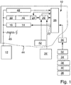
- the single figure shows a schematic representation of an exemplary embodiment of a device 10 according to the invention for determining a wing 12 of a door or the like.
- this is, for example, the wing 12 of a revolving door.
- the locking device 10 comprises at least one electric motor 14 operated as a generator; 16, whose motor shaft is connected to the wing 12 via a force transmission unit such that a respective movement of the wing 12 with a movement of the motor shaft.
- the power transmission unit can in each case in particular also include a gear 18; 20 include.
- the motor terminals of at least one electric motor 14; 16 are connected to a damping circuit 22 for damping the wing movements, whereby according to that in the only one Fig. 1 Embodiment shown, only the motor terminals of the electric motor 14 are connected to such a damping circuit 22.
- only the electric motor 14 serves as a damping motor.
- the motor shaft can have at least one electric motor 14; 16 can be acted upon by a brake unit 24, wherein according to the in Fig. 1 illustrated embodiment, only the motor shaft of the electric motor 16 can be acted upon by such a brake unit 24.
- the brake unit 24 can in particular comprise an electromagnetic brake.
- the locking device 10 comprises control electronics with an evaluation and / or control unit 46, via which the brake unit 24 can be controlled.
- At least one electric motor 14 operated as a generator; 16 is connected via its motor terminals to a charging circuit for charging an energy store 28.
- a charging circuit for charging an energy store 28.
- the charging circuit is part of the evaluation and / or control electronics of the locking device 10.
- the damping circuit 22 in particular can also be integrated in the evaluation and / or control unit 26.
- the evaluation and / or control unit 26 can be supplied with electrical energy via the charging circuit or the energy store 28 which can be charged via this. Self-sufficient operation without the supply of electrical energy from the outside is thus possible.
- the brake unit 24 is either monostable or bistable according to the open-circuit principle.
- the locking device thus comprises two electric motors 14 each operated as a generator; 16, one of which, namely the electric motor 14, is connected via its motor terminals to the damping circuit 22 and the other, namely the electric motor 16, is connected via its motor terminals to the charging circuit for charging the energy store 28.
- the motor shaft of the electric motor 16 connected to the charging circuit via its motor terminals and / or the motor shaft of the electric motor 14 connected to the damping circuit 22 via its motor terminals can be acted upon by the braking unit 24.
- a braking unit is assigned to each electric motor.
- the exemplary embodiment shown is only capable of applying a brake unit 24 to the motor shaft of the electric motor 16 connected via its motor terminals to the charging circuit for charging the energy store 28.
- the damping circuit 22 which, like the charging circuit with the associated energy store 28, is assigned to the evaluation and control electronics, can be controlled via the evaluation and / or control unit 26. As already mentioned, This damping circuit 22 can also be integrated in the evaluation and / or control unit 26.
- the damping circuit 22 connected to the motor terminals of the electric motor 14 serving as a damping motor can comprise at least one switching element which can be controlled via the evaluation and / or control unit 26 and via which, for example, pulse width modulation of the motor current can be carried out.
- the movement of the wing 12 can be damped in particular depending on the position, speed and / or direction of rotation of the wing 12 by a corresponding, for example pulse-width-modulated short circuit of the electric motor 14 serving as a damping motor.
- the brake unit 24 can be controlled via the evaluation and / or control unit 26, in particular for generating a time-limited determination of the wing 12.
- the brake unit 24 can be controlled via the evaluation and / or control unit 26, for example to set a predefinable closing delay of the wing 12.
- the brake unit 24 can also be controlled via the evaluation and / or control unit 26 as a function of output signals from a safety sensor system.
- both leaves 12 can each have at least one electric motor 14; 16 assigned and the motor shaft of at least one electric motor 14 assigned to a respective wing 12; 16 can be acted upon by a brake unit 24.
- the closing sequence of the two leaves 12 can be controlled and / or regulated via the evaluation and / or control unit 26.
- the brake unit 24 assigned to the wing 12 can also be controlled via the evaluation and / or control unit 26 such that a respective determination of the wing 12 is released in the event of a fire. This ensures that the sash is closed by the assigned mechanical memory in the event of a fire.
- the evaluation and / or control unit 26 can thus control the braking unit 24 and / or the damping circuit 22, for example as a function of a signal 30, which in the event of a delay, for example by a switch 32 and / or a person detector 34 and / or a safety sensor system 36 and / or in the case of a fire protection door by a fire detector and / or in the case of a double-leaf door with a passive leaf and an active leaf by a closing sequence specification 40 and / or the like can be specified.
- an additional accumulator or an additional battery 42 can be provided to supply the evaluation and / or control unit 26 with electrical energy.
- the energy stores 28, 28 'of the locking devices or door closers assigned to the two leaves 12 can be coupled to one another. Sufficient electrical energy is therefore always available, in particular for switching a bistable detection, if one wing is moved in each case, while the detection of the other must be held, as was already explained in more detail at the beginning.
- the locking device 10 can in particular be integrated in a door closer 44 with a mechanical energy store 46, which can be charged by manually opening the door leaf 12 with potential energy that can be used to close the door leaf 12.
- the mechanical energy store 46 of the door closer 44 can in particular comprise a spring unit.
- a time-limited detection of a door leaf in a generator-damped door closer for example for a delay in connection with a safety sensor, for a closing sequence for a double-leaf door and / or depending on at least one fire detector, can be implemented.
- the door closer which is damped by the generator, is provided with a monostable or bistable hold-open device and the supply of the hold-open device with electrical energy from an independent energy store is guaranteed.
- damping of the wing movements can be done in particular as in the DE 10 2015 200 284 B3 is described.
- the spring unit of the mechanical energy store 46 is tensioned.
- the electric motor 16 serving as a generator motor generates electrical energy via the charging circuit, which is stored in the energy store 28, the state of which can be monitored by the evaluation and / or control unit 26.
- the energy store 28 supplies the evaluation and / or control unit 26 with electrical energy.
- the movements of the wing 12 are dependent on the position, speed and / or direction of rotation of the wing 12 by the evaluation and / or control unit 26 via the damping circuit 22, for example by a pulse-width modulated short circuit of the motor terminals of the Damping motor serving electric motor 14 damped.
- the position, speed and / or direction of rotation of the vane 12 can be detected via corresponding measuring circuits 48 and transmitted to the evaluation and / or control unit 26.
- a time-limited determination of the wing 12 is possible by a corresponding control of the brake unit 24 assigned to the electric motor 16 serving as a generator motor by the evaluation and / or control unit 26.
Description
Die Erfindung betrifft eine Einrichtung zur Feststellung eines Flügels einer Tür oder dergleichen mit wenigstens einem als Generator betriebenen Elektromotor, dessen Motorwelle über eine Kraftübertragungseinheit mit dem Flügel in Wirkverbindung steht. Sie betrifft ferner einen Türschließer mit einer solchen Feststelleinrichtung.The invention relates to a device for detecting a wing of a door or the like with at least one electric motor operated as a generator, the motor shaft of which is operatively connected to the wing via a power transmission unit. It also relates to a door closer with such a locking device.
Türschließer für bewegliche Türflügel mit einem mechanischen Energiespeicher und einer Dämpfungseinrichtung zur Dämpfung der Flügelbewegung sind allgemein bekannt. Beim manuellen Öffnen des Türflügels wird der mechanische Energiespeicher mit potentieller Energie aufgeladen, welche den losgelassenen Türflügel wieder schließt. Der mechanische Energiespeicher kann beispielsweise eine Feder umfassen, die durch das manuelle Öffnen des Türflügels gespannt wird und sich mit dem Schließen des Türflügels wieder entspannt.Door closers for movable door leaves with a mechanical energy store and a damping device for damping the leaf movement are generally known. When the door leaf is opened manually, the mechanical energy store is charged with potential energy, which closes the released door leaf again. The mechanical energy store can comprise, for example, a spring which is tensioned by the manual opening of the door leaf and relaxes again when the door leaf is closed.
Es sind auch bereits Antriebe zum Betätigen eines beweglichen Türflügels mit einer Dämpfungseinrichtung zur Dämpfung der Flügelbewegung bekannt, die einen als Generator betriebenen Elektromotor umfassen, dessen Motorwelle durch eine Bewegung des Türflügels drehbar ist und an dessen Motorklemmen eine bewegungsabhängige Motorspannung entsteht, die an einen Dämpfungsstromkreis angelegt ist. Der Dämpfungsstromkreis kann wenigstens ein beispielsweise als Feldeffekttransistor ausgeführtes Schaltelement aufweisen, über das die Motorklemmen kurzgeschlossen werden können. Im Dämpfungsstromkreis ist eine Drain-Source-Strecke des Feldeffekttransistors angeordnet. Eine Spannung zwischen Gate und Source des Feldeffekttransistors wird über ein Potentiometer eingestellt, das in Parallelschaltung mit der Drain-Source-Strecke des Feldeffekttransistors angeordnet ist. Ein Spannungsabgriff des Potentiometers ist an den Gate-Anschluss des Feldeffekttransistors angeschlossen. Damit wird der Feldeffekttransistor als spannungsabhängiger Lastwiderstand für den Elektromotor betrieben, so dass die Dämpfungskraft der Dämpfungsvorrichtung von der Ausgangsspannung des als Generator betriebenen Elektromotors abhängig ist.There are also drives for actuating a movable door leaf with a damping device for damping the leaf movement, which comprise an electric motor operated as a generator, the motor shaft of which can be rotated by a movement of the door leaf and a movement-dependent motor voltage is generated at the motor terminals and applied to a damping circuit is. The damping circuit can have at least one switching element, for example in the form of a field effect transistor, via which the motor terminals can be short-circuited. A drain-source path of the field effect transistor is arranged in the damping circuit. A voltage between the gate and source of the field effect transistor is set via a potentiometer, which is arranged in parallel with the drain-source path of the field effect transistor. A voltage tap of the potentiometer is connected to the gate connection of the field effect transistor. The field effect transistor is thus operated as a voltage-dependent load resistor for the electric motor, so that the damping force of the damping device is dependent on the output voltage of the electric motor operated as a generator.
Es sind auch bereits Feststelleinrichtungen bekannt, mit denen ein Türflügel bei bestimmten Öffnungswinkeln feststellbar ist. Insbesondere bei Türöffnern mit einem eine Federeinheit umfassenden mechanischen Speicher und einem Generatormotor, dessen Motorklemmen zur Dämpfung des Flügels an einen Dämpfungsstromkreis angeschlossen sind, besteht nun aber das Problem, dass aufgrund der elektrischen Verluste der Dämpfungsmotor die Bewegung des Türflügels beim Schließen nur dämpfen, jedoch nicht anhalten, d.h. feststellen kann. Solange die Federkraft des mechanischen Speichers größer ist als die Reibung, wird die Federkraft den Türflügel selbst dann in Schließrichtung langsam weiterbewegen, wenn der Dämpfungsmotor vollständig kurzgeschlossen ist.Locking devices are also already known, with which a door leaf can be locked at certain opening angles. Particularly in the case of door openers with a mechanical memory comprising a spring unit and a generator motor, the motor terminals of which are connected to a damping circuit for damping the leaf, there is now the problem that due to the electrical losses of the damping motor, the movement of the door leaf only dampens when closing, but not stop, ie can determine. As long as the spring force of the mechanical memory is greater than the friction, the spring force will continue to move the door leaf slowly in the closing direction even if the damping motor is completely short-circuited.
Die
Die
Die
Der Erfindung liegt die Aufgabe zugrunde, eine Feststelleinrichtung sowie einen Türschließer der eingangs genannten Art anzugeben, mit denen die zuvor erwähnten Probleme beseitigt sind. Dabei soll insbesondere eine zuverlässige Feststellung des Flügels unter möglichst effektiver Nutzung der bei einem Antrieb mit generatorischer Dämpfung der Flügelbewegung bereits vorhandenen Komponenten auf möglichst einfache und entsprechend kostengünstige Weise verwirklicht werden.The invention has for its object to provide a locking device and a door closer of the type mentioned, with which the aforementioned problems are eliminated. In particular, a reliable determination of the wing is to be realized in the simplest possible and correspondingly cost-effective manner, using the components already present in a drive with regenerative damping of the wing movement as effectively as possible.
Erfindungsgemäß wird diese Aufgabe durch eine Feststelleinrichtung mit den Merkmalen des Anspruchs 1 sowie einen Türschließer mit den Merkmalen des Anspruchs 14 gelöst. Bevorzugte Ausführungsformen der erfindungsgemäßen Feststelleinrichtung sowie des erfindungsgemäßen Türschließers ergeben sich aus den Unteransprüchen.According to the invention, this object is achieved by a locking device with the features of claim 1 and a door closer with the features of
Die erfindungsgemäße Einrichtung zur Feststellung eines Flügels einer Tür oder dergleichen umfasst wenigstens einen als Generator betriebenen Elektromotor, dessen Motorwelle über eine Kraftübertragungseinheit mit dem Flügel in Wirkverbindung steht. Dabei sind die Motorklemmen wenigstens eines als Generator arbeitenden Elektromotors zur Dämpfung der Flügelbewegungen an einen Dämpfungsstromkreis angeschlossen. Zur Feststellung des Flügels ist die Motorwelle wenigstens eines als Generator arbeitenden Elektromotors durch eine Bremseinheit beaufschlagbar.The device according to the invention for determining a wing of a door or the like comprises at least one electric motor operated as a generator, whose motor shaft is operatively connected to the wing via a power transmission unit. The motor terminals of at least one electric motor working as a generator are connected to a damping circuit for damping the wing movements. To determine the wing, the motor shaft of at least one electric motor working as a generator can be acted upon by a brake unit.
Aufgrund dieser Ausbildung wird auf einfache und entsprechend kostengünstige Weise eine zuverlässige Feststellung des Flügels gewährleistet, wobei die bei einem Antrieb mit generatorischer Dämpfung der Flügelbewegungen vorgesehenen Komponenten auf effektive Weise genutzt werden.On the basis of this design, a reliable determination of the wing is ensured in a simple and correspondingly cost-effective manner, the components provided in a drive with regenerative damping of the wing movements being used effectively.
Bevorzugt umfasst die Bremseinheit eine elektromagnetische Bremse.The brake unit preferably comprises an electromagnetic brake.
Erfindungsgemäß umfasst die Feststelleinrichtung eine Auswerte- und/oder Steuereinheit, über die die Bremseinheit ansteuerbar ist. Über eine solche Auswerte- und/oder Steuereinheit ist eine variable Einstellung der Feststellung, insbesondere eine zeitbegrenzte Feststellung und/oder dergleichen möglich.According to the invention, the locking device comprises an evaluation and / or control unit, via which the brake unit can be controlled. Such an evaluation and / or control unit enables a variable setting of the determination, in particular a time-limited determination and / or the like.
Erfindungsgemäß ist wenigstens ein als Generator betriebener Elektromotor über seine Motorklemmen an einen Ladestromkreis angeschlossen, über den die Auswerte- und/oder Steuereinheit mit elektrischer Energie versorgbar ist. Es ist somit ein autarker, d.h. auch ohne Energiezufuhr von außen möglicher Betrieb der Feststelleinrichtung gewährleistet.According to the invention, at least one electric motor operated as a generator is connected via its motor terminals to a charging circuit via which the evaluation and / or control unit can be supplied with electrical energy. It is therefore a self-sufficient, i.e. Operation of the locking device possible even without external energy supply.
Die Bremseinheit kann beispielsweise entsprechend dem Arbeitsstromprinzip monostabil betreibbar sein. Dabei kann die Bremseinheit im Ruhezustand bzw. bei nicht anliegendem Steuersignal die betreffende wenigstens eine Motorwelle zur Feststellung des Flügels beaufschlagen. Sobald ein Steuersignal angelegt wird oder spätestens sobald ein über den Ladestromkreis aufzuladender Energiespeicher leer ist, wird die Bremseinheit gelöst.For example, the brake unit can be operated in a monostable manner in accordance with the open-circuit principle. The brake unit can act on the relevant at least one motor shaft to determine the wing in the idle state or when the control signal is not present. As soon as a control signal is applied or at the latest as soon as an energy store to be charged via the charging circuit is empty, the brake unit is released.
Gemäß einer alternativen Ausführungsform kann die Bremseinheit auch bistabil betreibbar sein. Dies bringt unter anderem den Vorteil mit sich, dass nur während der Schaltzeiten Energie aus dem Energiespeicher benötigt wird. Dabei ist es gegebenenfalls zweckmäßig, wenn die Auswerte- und/oder Steuereinheit den über den Ladestromkreis aufladbaren Energiespeicher überwacht, um die Feststellung des Flügels gegebenenfalls rechtzeitig lösen zu können, solange die in diesem Energiespeicher gespeicherte Energie noch ausreicht.According to an alternative embodiment, the brake unit can also be operated bistably. Among other things, this has the advantage that energy from the energy store is only required during the switching times. In this case, it may be expedient if the evaluation and / or control unit monitors the energy store that can be charged via the charging circuit in order to be able to release the wing if necessary in time, as long as the energy stored in this energy store is still sufficient.
Erfindungsgemäß umfasst die Feststelleinrichtung wenigstens zwei jeweils als Generator betriebene Elektromotoren, von denen einer über seine Motorklemmen an den Dämpfungsstromkreis und der andere über seine Motorklemmen an den Ladestromkreis angeschlossen ist. In diesem Fall dient der eine Elektromotor somit als Dämpfungsmotor zur Dämpfung der Flügelbewegungen und der andere Elektromotor als Generatormotor zur Erzeugung der zur Aufladung des Energiespeichers über den Ladestromkreis benötigten Energie.According to the invention, the locking device comprises at least two electric motors each operated as a generator, one of which is connected to the damping circuit via its motor terminals and the other is connected to the charging circuit via its motor terminals. In this case, the one electric motor thus serves as a damping motor for damping the wing movements and the other electric motor serves as a generator motor for generating the energy required to charge the energy store via the charging circuit.
Dabei ist zur Feststellung des Flügels die Motorwelle des über seine Motorklemmen an den Ladestromkreis angeschlossenen Elektromotors und/oder die Motorwelle des über seine Motorklemmen an den Dämpfungsstromkreis angeschlossenen Elektromotors durch die Bremseinheit beaufschlagbar.To determine the wing, the motor shaft of the electric motor connected to the charging circuit via its motor terminals and / or the motor shaft of the electric motor connected to the damping circuit via its motor terminals can be acted upon by the braking unit.
Von Vorteil ist insbesondere auch, wenn der Dämpfungsstromkreis über die Auswerte- und/oder Steuereinheit ansteuerbar ist.It is also particularly advantageous if the damping circuit can be controlled via the evaluation and / or control unit.
Dabei umfasst der Dämpfungsstromkreis bevorzugt wenigstens ein über die Auswerte- und/oder Steuereinheit ansteuerbares Schaltelement, über das eine Pulsweitenmodulation des Motorstroms durchführbar ist. Die Pulsweitenmodulation des Motorstroms ermöglicht in vorteilhafter Weise die Vorgabe einer Schließzeit, welche beispielsweise durch Regelung der Schließgeschwindigkeit als Funktion des Öffnungswinkels des Türflügels konstant gehalten werden kann. Die gewünschte Schließzeit kann in vorteilhafter Weise unabhängig von Temperatur, Alterung und Reibung vorgegeben und eingestellt werden.The damping circuit preferably comprises at least one switching element which can be controlled via the evaluation and / or control unit and via which pulse width modulation of the motor current is feasible. The pulse width modulation of the motor current advantageously allows a closing time to be specified, which can be kept constant, for example, by regulating the closing speed as a function of the opening angle of the door leaf. The desired closing time can advantageously be specified and set independently of temperature, aging and friction.
Bevorzugt ist die Bremseinheit über die Auswerte- und/oder Steuereinheit zur Erzeugung einer zeitbegrenzten Feststellung des Flügels ansteuerbar.The brake unit can preferably be controlled via the evaluation and / or control unit to generate a time-limited determination of the wing.
Gemäß einer zweckmäßigen praktischen Ausführungsform der erfindungsgemäßen Feststelleinrichtung ist die Bremseinheit über die Auswerte- und/oder Steuereinheit zur Einstellung einer vorgebbaren Schließverzögerung des Flügels ansteuerbar. Im Fall eines Türschließers kann der geöffnete Flügel somit erst nach einer bestimmten Zeit schließen. Es kann damit beispielsweise dem Umstand Rechnung getragen werden, dass das Passieren der Tür einige Zeit benötigt, um beispielsweise größere Gegenstände durch die Tür zu transportieren. Wollen mehrere Personen die Tür passieren, so wird ebenfalls mehr Zeit benötigt, während der die Tür offengehalten werden soll.According to an expedient practical embodiment of the locking device according to the invention, the brake unit can be controlled via the evaluation and / or control unit to set a predefinable closing delay of the leaf. In the case of a door closer, the opened sash can only close after a certain time. It can, for example, take into account the fact that passing the door takes some time, for example to transport larger objects through the door. If several people want to pass the door, more time is also required during which the door is to be kept open.
Gemäß einer weiteren vorteilhaften Ausführungsform der erfindungsgemäßen Feststelleinrichtung ist die Bremseinheit über die Auswerte- und/oder Steuereinheit in Abhängigkeit von Ausgangssignalen einer Sicherheitssensorik ansteuerbar.According to a further advantageous embodiment of the locking device according to the invention, the brake unit can be controlled via the evaluation and / or control unit as a function of output signals from a safety sensor system.
Wird durch das Schließen des Türflügels beispielsweise eine Person gefährdet, so kann der Türflügel zumindest für eine kurze Zeit angehalten werden, damit die Person sich aus dem Gefahrenbereich entfernen kann.If, for example, a person is endangered by the closing of the door leaf, the door leaf can be stopped at least for a short time so that the person can move away from the danger area.
Gemäß einer weiteren bevorzugten praktischen Ausführungsform der erfindungsgemäßen Feststelleinrichtung ist bei einer zweiflügeligen Tür mit einem Standflügel und einem Gangflügel beiden Flügeln jeweils wenigstens ein als Generator betriebener Elektromotor zugeordnet und zur Feststellung der beiden Flügel jeweils die Motorwelle eines einem jeweiligen Flügel zugeordneten Elektromotors durch eine Bremseinheit beaufschlagbar.According to a further preferred practical embodiment of the locking device according to the invention, in the case of a double-leaf door with a passive leaf and a moving wing is assigned to both wings at least one electric motor operated as a generator, and the motor shaft of an electric motor assigned to a respective wing can be acted upon by a brake unit to determine the two wings.
Dabei kann über die Auswerte- und/oder Steuereinheit insbesondere die Schließfolge der beiden Flügel steuer- und/oder regelbar sein.In particular, the closing sequence of the two leaves can be controlled and / or regulated via the evaluation and / or control unit.
Es kann somit insbesondere eine zweiflügelige Brandschutztür mit einer erfindungsgemäßen Feststelleinrichtung bzw. entsprechenden erfindungsgemäßen Türschließern ausgestattet sein. Wird der Standflügel geöffnet, während der Gangflügel schließt, soll der Gangflügel den Schließvorgang zumindest solange unterbrechen, bis der Standflügel wieder weiter geschlossen ist als der Gangflügel. Umgekehrt soll der Standflügel automatisch auslösen, falls der Gangflügel manuell ausgelöst wird.In particular, a two-leaf fire door can therefore be equipped with a locking device according to the invention or corresponding door closers according to the invention. If the passive leaf is opened while the active leaf closes, the active leaf should interrupt the closing process at least until the passive leaf is closed further than the active leaf. Conversely, the passive leaf should trigger automatically if the active leaf is triggered manually.
Gemäß einer weiteren vorteilhaften Ausführungsform der erfindungsgemäßen Feststelleinrichtung ist bei einem Flügel einer Brandschutztür oder dergleichen die dem Flügel zugeordnete Bremseinheit über die Auswerte- und/oder Steuereinheit so ansteuerbar, dass eine jeweilige Feststellung des Flügels im Brandfall gelöst wird.According to a further advantageous embodiment of the locking device according to the invention, in the case of a wing of a fire protection door or the like, the brake unit assigned to the wing can be controlled via the evaluation and / or control unit such that a respective determination of the wing is released in the event of a fire.
Dabei kann die Feststellung wieder nach dem Arbeitsstromprinzip monostabil oder bistabil ausgeführt sein. Im Fall einer monostabilen Ausführung kann eine jeweilige Bremseinheit gelöst werden, sobald von einem Brandmelder ein Steuersignal eintrifft, spätestens jedoch, sobald der über den Ladestromkreis aufladbare Energiespeicher leer ist. Eine bistabile Ausführung bringt, wie bereits erwähnt, den Vorteil mit sich, dass nur während der Schaltzeiten Energie aus dem Energiespeicher benötigt wird. Über die Auswerte- und/oder Steuereinheit wird dann zweckmäßigerweise der Ladezustand des Energiespeichers überwacht, um die Feststellung rechtzeitig lösen zu können, solange die im Energiespeicher gespeicherte Energie noch ausreicht.The determination can again be made monostable or bistable according to the open-circuit principle. In the case of a monostable version, a respective brake unit can be released as soon as a control signal arrives from a fire detector, but at the latest as soon as the energy store that can be charged via the charging circuit is empty. As already mentioned, a bistable design has the advantage that energy from the energy store is only required during the switching times. The state of charge of the energy store is then expediently monitored via the evaluation and / or control unit in order to determine to be able to solve it in time as long as the energy stored in the energy storage is sufficient.
Über die Auswerte- und/oder Steuereinheit kann die wenigstens eine Bremseinheit somit insbesondere zur Einstellung einer vorgebbaren Schließverzögerung und/oder in Abhängigkeit von Ausgangssignalen einer Sicherheitssensorik und/oder zur Steuerung und/oder Regelung der Schließfolge bei einer zweiflügeligen Tür und/oder zum Lösen im Brandfall bei einem Flügel einer Brandschutztür ansteuerbar sein.Via the evaluation and / or control unit, the at least one brake unit can thus, in particular, be used to set a predefinable closing delay and / or depending on output signals from a safety sensor system and / or to control and / or regulate the closing sequence in the case of a double-leaf door and / or to release it Fire in the case of a wing of a fire door can be controlled.
Zur Feststellung eines Flügels kann erfindungsgemäß also wenigstens eine beispielsweise elektromagnetische Bremseinheit zur Beaufschlagung wenigstens einer Motorwelle wenigstens eines als Generator betriebenen Elektromotors vorgesehen sein. Aufgrund der in der Regel hohen Untersetzung des einem jeweiligen Elektromotor zugeordneten Getriebes reichen geringste Momente zum Halten der den Energiespeicher bildenden Federeinheit aus. Wie bereits erwähnt, kann eine jeweilige Bremseinheit monostabil oder bistabil ausgeführt sein.To determine a wing, according to the invention, at least one, for example, electromagnetic brake unit can be provided to act on at least one motor shaft of at least one electric motor operated as a generator. Due to the generally high reduction ratio of the transmission assigned to a respective electric motor, the smallest moments are sufficient to hold the spring unit forming the energy store. As already mentioned, a respective brake unit can be made monostable or bistable.
Soll ein mit einer erfindungsgemäßen Feststelleinrichtung versehener Türschließer grundsätzlich mit Schließverzögerung arbeiten, so wird kein externes Signal benötigt. Die Schließverzögerung kann als Parameter beispielsweise über eine Nahfeldkommunikation NFC (near field communication) in einen Datenspeicher eingegeben werden. Der Flügel schließt nach Ablauf der durch die Auswerte- und/oder Steuereinheit vorgebbaren Zeit oder sobald der über den Ladestromkreis aufladbare Energiespeicher leer ist. Für größere Zeiten kann die Energie im Energiespeicher mit einer zusätzlichen Batterie oder einem Akkumulator vergrößert werden.If a door closer provided with a locking device according to the invention is to operate with a closing delay, no external signal is required. The closing delay can be entered as parameters, for example via a near field communication NFC (near field communication) in a data memory. The wing closes after the time that can be predetermined by the evaluation and / or control unit or as soon as the energy store that can be charged via the charging circuit is empty. For longer times, the energy in the energy store can be increased with an additional battery or an accumulator.
Alternativ oder zusätzlich kann die Schließverzögerung auch über ein Signal gesteuert werden. Im einfachsten Fall kann ein Schalter oder dergleichen vorgesehen sein, um die feste Verzögerung ein- und auszuschalten. Die Schließverzögerung kann auch über eine Sensorik (zum Beispiel Passiv-Infrarot-Sensoren) gesteuert werden. Der Flügel kann in diesem Fall beispielsweise solange offen bleiben, wie von der Sensorik Personen erfasst werden, die die Tür passieren wollen. Auch in diesem Fall kann für möglichst große Verzögerungszeiten auch ein zusätzlicher Akkumulator oder eine Batterie eingesetzt werden. Es sind auch solche Ausführungen denkbar, bei denen die Sensorik mit einer eigenen Batterie und/oder einem eigenen Akkumulator versehen ist. Zudem kann eine entsprechende Sensorik auch im jeweiligen Türschließer integriert sein.Alternatively or additionally, the closing delay can also be controlled via a signal. In the simplest case, a switch or the like can be provided to switch the fixed delay on and off. The closing delay can also be controlled via a sensor system (e.g. passive infrared sensors). In this case, the sash can remain open, for example, as long as the sensor detects people who want to pass the door. In this case too, an additional accumulator or a battery can be used for the greatest possible delay times. Designs are also conceivable in which the sensor system is provided with its own battery and / or its own accumulator. A corresponding sensor system can also be integrated in the respective door closer.
Ist eine jeweilige Bremseinheit über die Auswerte- und/oder Steuereinheit in Abhängigkeit von Ausgangssignalen einer Sicherheitssensorik ansteuerbar, so kann beispielsweise die Bewegungsfläche wie beispielsweise eine Nebenschließkante des Flügels gesichert werden. Die betreffende Sicherheitssensorik kann mit einer eigenen Batterie oder einem eigenen Akkumulator versehen sein.If a respective brake unit can be controlled via the evaluation and / or control unit as a function of output signals from a safety sensor system, the movement surface, for example a secondary closing edge of the leaf, can be secured, for example. The relevant safety sensor system can be provided with its own battery or its own accumulator.
Ist der Flügel offen und liefert die Sensorik ein aktives Signal, so kann der Flügel entsprechend einer vorgebbaren Schließverzögerung offengehalten werden. Liefert die Sensorik während des Schließens des Flügels ein aktives Steuersignal, so kann die Auswerte- und/oder Steuereinheit den Flügel zunächst mit maximaler Dämpfung, d.h. beispielsweise einer Pulsweitenmodulation von 100%, dämpfen und anschließend zusätzlich die wenigstens eine Bremseinheit zum Feststellen des Flügels entgegen der Kraft der Federeinheit aktivieren.If the leaf is open and the sensor system supplies an active signal, the leaf can be kept open according to a predefinable closing delay. If the sensor system supplies an active control signal while the wing is closing, the evaluation and / or control unit can initially operate the wing with maximum damping, i.e. dampen pulse width modulation of 100%, for example, and then additionally activate the at least one brake unit for locking the wing against the force of the spring unit.
Bei der Steuerung und/oder Regelung der Schließfolge im Fall einer zweiflügligen Tür können die den beiden Türflügeln zugeordneten Energiespeicher gekoppelt sein. Damit kann insbesondere zum Schalten einer bistabilen Feststellung stets für genügend Energie gesorgt werden, indem die beiden Flügel der zweiflügligen Tür so angesteuert werden, dass sich der eine Flügel stets bewegt, wenn die Feststellung des anderen gehalten werden muss. Stehen der Gangflügel und der Standflügel beispielsweise offen und wird der Standflügel manuell gelöst, so dass dieser schließt, so kann die Feststellung des Gangflügels kurz vor Erreichen der Schließlage durch den Standflügel gelöst werden. Wird dagegen bei offenstehenden Flügeln der Gangflügel manuell gelöst, so kann die Feststellung des Standflügels unmittelbar freigegeben werden. Wird der Standflügel geöffnet während der Gangflügel schließt, kann der Gangflügel angehalten werden, bis der Standflügel wieder weiter geschlossen ist als der Gangflügel.When controlling and / or regulating the closing sequence in the case of a double-leaf door, the energy stores assigned to the two door leaves can be coupled. Sufficient energy can thus always be provided, in particular for switching a bistable locking device, by actuating the two leaves of the double-leaf door in such a way that one wing always moves when the other device must be held open. Standing the active wing and the passive wing For example, open and if the passive leaf is released manually so that it closes, the determination of the active leaf can be solved by the passive leaf shortly before reaching the closed position. If, on the other hand, the active leaf is released manually when the sash is open, the fixing of the passive leaf can be released immediately. If the passive leaf is opened while the active leaf closes, the active leaf can be stopped until the passive leaf is closed further than the active leaf.
Erfindungsgemäß ist somit insbesondere auch eine autarke elektrische Schließfolge für Türschließer mit generatorischer Dämpfung realisierbar.According to the invention, an autonomous electrical closing sequence for door closers with regenerative damping can thus also be implemented in particular.
Ein jeweiliger als Generator betriebener Elektromotor kann insbesondere als permanent magnetisch erregter Gleichstrommotor ausgeführt sein.A respective electric motor operated as a generator can in particular be designed as a permanently magnetically excited direct current motor.
Der erfindungsgemäße Türschließer umfasst einen mechanischen Energiespeicher, der durch manuelles Öffnen des Türflügels mit potentieller Energie aufladbar ist, die zum Schließen des Türflügels nutzbar ist, sowie eine Feststelleinrichtung. Er zeichnet sich dadurch aus, dass die Feststelleinrichtung entsprechend der Erfindung ausgeführt ist.The door closer according to the invention comprises a mechanical energy store, which can be charged with potential energy by manually opening the door leaf, which energy can be used to close the door leaf, and a locking device. It is characterized in that the locking device is designed according to the invention.
Die Erfindung wird im Folgenden anhand der Zeichnung näher erläutert. In dieser zeigt die einzige Figur in schematischer Darstellung eine beispielhafte Ausführungsform einer erfindungsgemäßen Einrichtung 10 zur Feststellung eines Flügels 12 einer Tür oder dergleichen. Dabei handelt es sich im vorliegenden Fall beispielsweise um den Flügel 12 einer Drehtür.The invention is explained in more detail below with reference to the drawing. In this, the single figure shows a schematic representation of an exemplary embodiment of a
Die Feststelleinrichtung 10 umfasst wenigstens einen als Generator betriebenen Elektromotor 14; 16, dessen Motorwelle über eine Kraftübertragungseinheit so mit dem Flügel 12 verbunden ist, dass eine jeweilige Bewegung des Flügels 12 mit einer jeweiligen Bewegung der Motorwelle einhergeht. Dabei kann die Kraftübertragungseinheit u.a. jeweils insbesondere auch ein Getriebe 18; 20 umfassen.The locking
Die Motorklemmen wenigstens eines als Generator arbeitenden Elektromotors 14; 16 sind zur Dämpfung der Flügelbewegungen an einen Dämpfungsstromkreis 22 angeschlossen, wobei gemäß dem in der einzigen
Zur Feststellung des Flügels 12 kann die Motorwelle wenigstens eines als Generator arbeitenden Elektromotors 14; 16 durch eine Bremseinheit 24 beaufschlagbar sein, wobei gemäß dem in der
Die Feststelleinrichtung 10 umfasst eine Steuerelektronik mit einer Auswerte- und/oder Steuereinheit 46, über die die Bremseinheit 24 ansteuerbar ist.The locking
Wenigstens ein als Generator betriebener Elektromotor 14; 16 ist über seine Motorklemmen an einen Ladestromkreis zum Aufladen eines Energiespeichers 28 angeschlossen. Beim in der
Über den Ladestromkreis bzw. den über diesen aufladbaren Energiespeicher 28 ist die Auswerte- und/oder Steuereinheit 26 mit elektrischer Energie versorgbar. Es ist somit ein autarker Betrieb ohne Zufuhr elektrischer Energie von außen möglich.The evaluation and / or
Die Bremseinheit 24 ist entweder entsprechend dem Arbeitsstromprinzip monostabil betreibbar oder bistabil betreibbar.The
Beim in der
Zur Feststellung des Flügels 12 ist grundsätzlich die Motorwelle des über seine Motorklemmen an den Ladestromkreis angeschlossenen Elektromotors 16 und/oder die Motorwelle des über seine Motorklemmen an den Dämpfungsstromkreis 22 angeschlossenen Elektromotors 14 durch die Bremseinheit 24 beaufschlagbar. Grundsätzlich ist auch eine solche Ausführung denkbar, bei der jedem Elektromotor eine solche Bremseinheit zugeordnet ist. Beim in der
Der Dämpfungsstromkreis 22, der ebenso wie der Ladestromkreis mit zugeordnetem Energiespeicher 28 der Auswerte- und Steuerelektronik zugeordnet ist, ist über die Auswerte- und/oder Steuereinheit 26 ansteuerbar. Wie bereits erwähnt, kann dieser Dämpfungsstromkreis 22 auch in der Auswerte- und/oder Steuereinheit 26 integriert sein.The damping
Der an die Motorklemmen des als Dämpfungsmotor dienenden Elektromotors 14 angeschlossene Dämpfungsstromkreis 22 kann wenigstens ein über die Auswerte- und/oder Steuereinheit 26 ansteuerbares Schaltelement umfassen, über das beispielsweise eine Pulsweitenmodulation des Motorstroms durchführbar ist. Dabei kann die Bewegung des Flügels 12 insbesondere in Abhängigkeit von der Position, Geschwindigkeit und/oder Drehrichtung des Flügels 12 durch einen entsprechenden beispielsweise pulsweitenmodulierten Kurzschluss des als Dämpfungsmotor dienenden Elektromotors 14 gedämpft werden.The damping
Die Bremseinheit 24 ist über die Auswerte- und/oder Steuereinheit 26 insbesondere zur Erzeugung einer zeitbegrenzten Feststellung des Flügels 12 ansteuerbar.The
Dabei ist die Bremseinheit 24 über die Auswerte- und/oder Steuereinheit 26 beispielsweise zur Einstellung einer vorgebbaren Schließverzögerung des Flügels 12 ansteuerbar.The
Alternativ oder zusätzlich kann die Bremseinheit 24 über die Auswerte- und/oder Steuereinheit 26 auch in Abhängigkeit von Ausgangssignalen einer Sicherheitssensorik ansteuerbar sein.As an alternative or in addition, the
Alternativ oder zusätzlich kann bei einer zweiflügligen Tür mit einem Standflügel und einem Gangflügel auch beiden Flügeln 12 jeweils wenigstens ein als Generator betriebener Elektromotor 14; 16 zugeordnet und zur Feststellung der beiden Flügel 12 jeweils die Motorwelle wenigstens eines einem jeweiligen Flügel 12 zugeordneten Elektromotors 14; 16 durch eine Bremseinheit 24 beaufschlagbar sein. Dabei kann über die Auswerte- und/oder Steuereinheit 26 insbesondere die Schließfolge der beiden Flügel 12 steuer- und/oder regelbar sein.Alternatively or additionally, in the case of a two-leaf door with a fixed leaf and a moving leaf, both leaves 12 can each have at least one
Alternativ oder zusätzlich kann bei einem Flügel 12 einer Brandschutztür oder dergleichen die dem Flügel 12 zugeordnete Bremseinheit 24 über die Auswerte- und/oder Steuereinheit 26 auch so ansteuerbar sein, dass eine jeweilige Feststellung des Flügels 12 im Brandfall gelöst wird. Damit ist sichergestellt, dass der Flügel im Brandfall durch den zugeordneten mechanischen Speicher geschlossen wird.As an alternative or in addition, in the case of a
Wie aus der
Insbesondere für größere Verzögerungszeiten kann auch ein zusätzlicher Akkumulator oder eine zusätzliche Batterie 42 zur Versorgung der Auswerte- und/oder Steuereinheit 26 mit elektrischer Energie vorgesehen sein. Im Fall einer zweiflügligen Tür können die Energiespeicher 28, 28' der den beiden Flügeln 12 zugeordneten Feststelleinrichtungen bzw. Türschließern miteinander gekoppelt werden. Insbesondere zum Schalten einer bistabilen Feststellung steht somit stets genügend elektrische Energie zur Verfügung, wenn ein Flügel jeweils bewegt wird, während die Feststellung des anderen gehalten werden muss, wie dies eingangs bereits näher erläutert wurde.For longer delay times in particular, an additional accumulator or an
Wie der
Mit einer erfindungsgemäßen Feststelleinrichtung 10 ist somit insbesondere eine zeitlich begrenzte Feststellung eines Türflügels bei einem generatorisch gedämpften Türschließer beispielsweise für eine Schließverzögerung in Verbindung mit einem Sicherheitssensor, für eine Schließfolge bei einer zweiflügeligen Tür und/oder in Abhängigkeit von wenigstens einem Brandmelder realisierbar. Dabei ist der generatorisch gedämpfte Türschließer mit einer monostabilen oder bistabilen Feststellung versehen und die Versorgung der Feststellung mit elektrischer Energie aus einem autarken Energiespeicher gewährleistet.With a
Im Übrigen kann die Dämpfung der Flügelbewegungen insbesondere so erfolgen, wie dies in der
Beim Öffnen des Türflügels 12 wird die Federeinheit des mechanischen Energiespeichers 46 gespannt. Gleichzeitig drehen die beiden Elektromotoren 14, 16. Der als Generatormotor dienende Elektromotor 16 erzeugt über den Ladestromkreis elektrische Energie, die im Energiespeicher 28 gespeichert wird, dessen Zustand durch die Auswerte- und/oder Steuereinheit 26 überwacht werden kann. Der Energiespeicher 28 versorgt die Auswerte- und/oder Steuereinheit 26 mit elektrischer Energie. Die Bewegungen des Flügels 12 werden in Abhängigkeit von der Position, Geschwindigkeit und/oder Drehrichtung des Flügels 12 durch die Auswerte- und/oder Steuereinheit 26 über den Dämpfungsstromkreis 22 beispielsweise durch einen pulsweitenmodulierten Kurzschluss der Motorklemmen des als Dämpfungsmotor dienenden Elektromotors 14 gedämpft. Position, Geschwindigkeit und/oder Drehrichtung des Flügels 12 können über entsprechende Messkreise 48 erfasst und an die Auswerte- und/oder Steuereinheit 26 übermittelt werden. Für bestimmte Situationen ist eine zeitbegrenzte Feststellung des Flügels 12 durch eine entsprechende Ansteuerung der dem als Generatormotor dienenden Elektromotor 16 zugeordneten Bremseinheit 24 durch die Auswerte- und/oder Steuereinheit 26 möglich.When the
- 1010th
- FeststelleinrichtungLocking device
- 1212th
- Flügelwing
- 1414
- ElektromotorElectric motor
- 1616
- ElektromotorElectric motor
- 1818th
- Getriebetransmission
- 2020
- Getriebetransmission
- 2222
- DämpfungsstromkreisDamping circuit
- 2424th
- BremseinheitBrake unit
- 2626
- Auswerte- und / oder SteuereinheitEvaluation and / or control unit
- 2828
- EnergiespeicherEnergy storage
- 3030th
- Signalsignal
- 3232
- Schaltercounter
- 3434
- PersonendetektorPerson detector
- 3636
- SicherheitssensorikSafety sensors
- 3838
- BrandmelderFire alarm
- 4040
- SchließfolgeClosing sequence
- 4242
- zusätzlicher Akkumulator / Batterieadditional accumulator / battery
- 4444
- TürschließerDoor closer
- 4646
- mechanischer Energiespeichermechanical energy storage
- 4848
- MesskreiseMeasuring circuits
Claims (14)
- Locking device (10) for locking a leaf (12) of a door or the like, comprising at least one electric motor (14; 16) which is operated as a generator and the motor shaft of which is operatively connected to the leaf (12) by means of a force-transmitting unit, wherein the motor terminals of at least one electric motor (14; 16) operating as a generator are connected to an electrical damping circuit (22) for the purpose of damping the leaf movements, and the motor shaft of at least one electric motor (14; 16) operating as a generator can be acted on by a braking unit (24) of the locking device for the purpose of locking the leaf (12), wherein the locking device (10) comprises an evaluation and/or control unit (26) by means of which the braking unit (24) can be actuated, and at least one electric motor (14; 16) which is operated as a generator is connected to an electrical charging circuit by means of its motor terminals, it being possible for electrical energy to be supplied to the evaluation and/or control unit (26) by means of the said electrical charging circuit, wherein the locking device (10) comprises at least two electric motors (14; 16) which are each operated as a generator and one of which is connected to the electrical damping circuit (22) by means of its motor terminals and the other of which is connected to the electrical charging circuit by means of its motor terminals, wherein the motor shaft of the electric motor (16) which is connected to the electrical charging circuit by means of its motor terminals and/or the motor shaft of the electric motor (14) which is connected to the electrical damping circuit (22) by means of its motor terminals can be acted on by the braking unit (24) for the purpose of locking the leaf (12).
- Locking device according to Claim 1,
characterized in that the braking unit (24) comprises an electromagnetic brake. - Locking device according to at least one of the preceding claims, characterized in that the braking unit (24) can be operated in a monostable manner in accordance with the open-circuit principle.
- Locking device according to either of Claims 1 and 2,
characterized in that the braking unit (24) can be operated in a bistable manner. - Locking device according to at least one of the preceding claims,
characterized in that the electrical damping circuit (22) can be actuated by means of the evaluation and/or control unit (26). - Locking device according to Claim 5,
characterized in that the electrical damping circuit (22) comprises at least one switching element which can be actuated by means of the evaluation and/or control unit (26) and by means of which pulse-width modulation of the motor current can be carried out. - Locking device according to at least one of the preceding claims,
characterized in that the braking unit (24) can be actuated by means of the evaluation and/or control unit (26) for the purpose of generating time-limited locking of the leaf (12). - Locking device according to at least one of the preceding claims,
characterized in that the braking unit (24) can be actuated by means of the evaluation and/or control unit (26) for the purpose of adjusting a prespecifiable closing deceleration of the leaf (12). - Locking device according to at least one of the preceding claims,
characterized in that the braking unit (24) can be actuated by means of the evaluation and/or control unit (26) depending on output signals of a safety sensor system. - Locking device according to at least one of the preceding claims,
characterized in that, in the case of a two-leaf door with a passive leaf and an active leaf, at least one electric motor (14; 16) which is operated as a generator is assigned to each of the two leaves (12), and the motor shaft of at least one electric motor, which is associated with a respective leaf (12), can respectively be acted on by a braking unit (24) for the purpose of locking the two leaves (12). - Locking device according to Claim 10,
characterized in that the closing sequence of the two leaves (12) can be subjected to open-loop control and/or closed-loop control by means of the evaluation and/or control unit (26). - Locking device according to either of Claims 10 and 11,
characterized in that, in the case of a two-leaf door with a passive leaf and an active leaf, the evaluation and control unit (26) is equipped with an additional rechargeable battery or battery (42). - Locking device according to at least one of the preceding claims,
characterized in that, in the case of a leaf (12) of a fire door or the like, the braking unit (24) which is associated with the leaf can be actuated by means of the evaluation and/or control unit (26) such that respective locking of the leaf (12) is released in the event of a fire. - Door closer (44) comprising a mechanical energy store (46) which can be charged with potential energy by manually opening the door leaf, which potential energy can be used for closing the door leaf, and comprising a locking device, characterized in that the locking device (10) is designed according to at least one of the preceding claims.
Applications Claiming Priority (1)
| Application Number | Priority Date | Filing Date | Title |
|---|---|---|---|
| DE102017201939.5A DE102017201939A1 (en) | 2017-02-08 | 2017-02-08 | Locking device |
Publications (2)
| Publication Number | Publication Date |
|---|---|
| EP3361027A1 EP3361027A1 (en) | 2018-08-15 |
| EP3361027B1 true EP3361027B1 (en) | 2020-07-29 |
Family
ID=60673657
Family Applications (1)
| Application Number | Title | Priority Date | Filing Date |
|---|---|---|---|
| EP17207592.1A Active EP3361027B1 (en) | 2017-02-08 | 2017-12-15 | Locking device |
Country Status (3)
| Country | Link |
|---|---|
| US (1) | US20180223578A1 (en) |
| EP (1) | EP3361027B1 (en) |
| DE (1) | DE102017201939A1 (en) |
Family Cites Families (15)
| Publication number | Priority date | Publication date | Assignee | Title |
|---|---|---|---|---|
| FI78767C (en) * | 1987-07-09 | 1989-09-11 | Waertsilae Oy Ab | FOERFARANDE OCH ARRANGEMANG FOER OPTIMERING AV FUNKTIONEN HOS EN DOERRSTAENGARE. |
| US5018304A (en) * | 1990-05-10 | 1991-05-28 | F. L. Saino Manufacturing Co. | Door operator |
| DE19726021A1 (en) * | 1997-06-19 | 1998-12-24 | Geze Gmbh & Co | Hinged door or window operating drive system |
| US6078159A (en) * | 1999-02-17 | 2000-06-20 | The Chamberlain Group, Inc. | Method and apparatus for programming a logic board from switching power |
| DE10023760A1 (en) * | 1999-06-15 | 2000-12-21 | Geze Gmbh | A method for closing double overlapping door systems in which the first closing leaf generates the energy to close the outer leaf. |
| DE102006059285A1 (en) * | 2006-12-13 | 2008-06-19 | Dorma Gmbh + Co. Kg | Drive for rotary panel door has closer and drive sections that interact with driven shaft held in second holder and are arranged adjacent to each other in longitudinal direction and extending in extension direction of driven shaft |
| US20090260289A1 (en) * | 2008-04-18 | 2009-10-22 | Michael Carpenter | Door Safety System |
| US8390219B2 (en) * | 2010-07-29 | 2013-03-05 | Yale Security Inc. | Door operator with electrical back check feature |
| DE102011055491A1 (en) * | 2011-11-18 | 2013-05-23 | Dorma Gmbh + Co. Kg | Power door closers |
| CN108612428A (en) * | 2012-05-08 | 2018-10-02 | 施拉奇锁有限责任公司 | door closer system |
| DE102014212570B4 (en) * | 2014-06-30 | 2018-04-19 | Geze Gmbh | Blocking device for a closing sequence control device of a two-leaf revolving door system |
| DE102015200284B3 (en) | 2015-01-13 | 2015-10-29 | Geze Gmbh | Brake device for a movable door leaf and a corresponding door closer |
| EP3245367A1 (en) * | 2015-01-18 | 2017-11-22 | Assa Abloy Sicherheitstechnik GmbH | Door drive device with main drive and auxiliary drive |
| NZ752019A (en) * | 2016-12-22 | 2024-01-26 | Assa Abloy Entrance Systems Ab | Closing speed control in power off |
| DE102017201950A1 (en) * | 2017-02-08 | 2018-08-09 | Geze Gmbh | braking device |
-
2017
- 2017-02-08 DE DE102017201939.5A patent/DE102017201939A1/en active Pending
- 2017-12-15 EP EP17207592.1A patent/EP3361027B1/en active Active
-
2018
- 2018-02-06 US US15/889,889 patent/US20180223578A1/en not_active Abandoned
Non-Patent Citations (1)
| Title |
|---|
| None * |
Also Published As
| Publication number | Publication date |
|---|---|
| EP3361027A1 (en) | 2018-08-15 |
| DE102017201939A1 (en) | 2018-08-09 |
| US20180223578A1 (en) | 2018-08-09 |
Similar Documents
| Publication | Publication Date | Title |
|---|---|---|
| EP3325748B1 (en) | Door component comprising a controllable damping system | |
| EP1340877B1 (en) | Door drive | |
| EP3245732B1 (en) | Electromechanical drive for actuating a moveable wing and corresponding door | |
| EP3417135B1 (en) | Braking device for a moving door leaf and corresponding door closer | |
| EP2887535B1 (en) | Drive and control system for raising gates | |
| EP2780526A1 (en) | Servo door-closer | |
| EP3361028A1 (en) | Drive unit | |
| DE4231984A1 (en) | Electromechanical swing door operating drive - with data processor coupled to motor control ensuring controlled door movement according to stored programme | |
| DE3003877A1 (en) | CLAMP LOCKING DEVICE FOR AUTOMATICALLY OPERATED DOORS OR WINDOWS, ESPECIALLY ON VEHICLES | |
| DE102017210434A1 (en) | Electric door drive and security door | |
| EP2188476B1 (en) | Linear drive for sliding doors or the like | |
| EP3361027B1 (en) | Locking device | |
| DE102012210588A1 (en) | Automatic swing door system has drive unit that is connected with a smoke and fire sensor, and emergency power supply unit that is connected with the drive unit during fire over the switching device | |
| EP3361034A1 (en) | Fixing and/or emergency opening system | |
| DE4140197C2 (en) | Method for adjusting a component that can be actuated by external power | |
| DE19700828C5 (en) | Method for operating an automatic door system | |
| DE102016210986A1 (en) | Device for detecting a door or window sash | |
| DE102018008812A1 (en) | Fail-safe, battery-operated freewheel door closer | |
| DE102015104825C5 (en) | Method for operating a door drive, door drive control, door drive and swing door | |
| EP3575531B1 (en) | System for blocking the leaf of a door or a window | |
| DE102011078832A1 (en) | Building door i.e. low-energy door, for use as e.g. inner door that is utilized between two rooms of building, has control device actuating driving apparatus when recognizing locking request for locking door leaf in holding position | |
| DE102009047441A1 (en) | Method for operating e.g. rear flap of flap system of motor vehicle, involves assigning position indication of provisional maximum open position, and limiting movement of flap toward open position to provisional maximum open position | |
| EP3361029A1 (en) | Drive for a wing of a door or a window | |
| EP3067510B1 (en) | Drive for a curtain with an emergency supply for an electronic end deactivation system | |
| DE102013207453A1 (en) | Closing device of a building with an electromotive drive device |
Legal Events
| Date | Code | Title | Description |
|---|---|---|---|
| PUAI | Public reference made under article 153(3) epc to a published international application that has entered the european phase |
Free format text: ORIGINAL CODE: 0009012 |
|
| STAA | Information on the status of an ep patent application or granted ep patent |
Free format text: STATUS: THE APPLICATION HAS BEEN PUBLISHED |
|
| AK | Designated contracting states |
Kind code of ref document: A1 Designated state(s): AL AT BE BG CH CY CZ DE DK EE ES FI FR GB GR HR HU IE IS IT LI LT LU LV MC MK MT NL NO PL PT RO RS SE SI SK SM TR |
|
| AX | Request for extension of the european patent |
Extension state: BA ME |
|
| STAA | Information on the status of an ep patent application or granted ep patent |
Free format text: STATUS: REQUEST FOR EXAMINATION WAS MADE |
|
| 17P | Request for examination filed |
Effective date: 20190212 |
|
| RBV | Designated contracting states (corrected) |
Designated state(s): AL AT BE BG CH CY CZ DE DK EE ES FI FR GB GR HR HU IE IS IT LI LT LU LV MC MK MT NL NO PL PT RO RS SE SI SK SM TR |
|
| STAA | Information on the status of an ep patent application or granted ep patent |
Free format text: STATUS: EXAMINATION IS IN PROGRESS |
|
| 17Q | First examination report despatched |
Effective date: 20190619 |
|
| GRAP | Despatch of communication of intention to grant a patent |
Free format text: ORIGINAL CODE: EPIDOSNIGR1 |
|
| STAA | Information on the status of an ep patent application or granted ep patent |
Free format text: STATUS: GRANT OF PATENT IS INTENDED |
|
| INTG | Intention to grant announced |
Effective date: 20200323 |
|
| GRAS | Grant fee paid |
Free format text: ORIGINAL CODE: EPIDOSNIGR3 |
|
| GRAA | (expected) grant |
Free format text: ORIGINAL CODE: 0009210 |
|
| STAA | Information on the status of an ep patent application or granted ep patent |
Free format text: STATUS: THE PATENT HAS BEEN GRANTED |
|
| AK | Designated contracting states |
Kind code of ref document: B1 Designated state(s): AL AT BE BG CH CY CZ DE DK EE ES FI FR GB GR HR HU IE IS IT LI LT LU LV MC MK MT NL NO PL PT RO RS SE SI SK SM TR |
|
| REG | Reference to a national code |
Ref country code: CH Ref legal event code: EP |
|
| REG | Reference to a national code |
Ref country code: AT Ref legal event code: REF Ref document number: 1295992 Country of ref document: AT Kind code of ref document: T Effective date: 20200815 |
|
| REG | Reference to a national code |
Ref country code: IE Ref legal event code: FG4D Free format text: LANGUAGE OF EP DOCUMENT: GERMAN |
|
| REG | Reference to a national code |
Ref country code: DE Ref legal event code: R096 Ref document number: 502017006409 Country of ref document: DE |
|
| REG | Reference to a national code |
Ref country code: LT Ref legal event code: MG4D |
|
| REG | Reference to a national code |
Ref country code: NL Ref legal event code: MP Effective date: 20200729 |
|
| PG25 | Lapsed in a contracting state [announced via postgrant information from national office to epo] |
Ref country code: FI Free format text: LAPSE BECAUSE OF FAILURE TO SUBMIT A TRANSLATION OF THE DESCRIPTION OR TO PAY THE FEE WITHIN THE PRESCRIBED TIME-LIMIT Effective date: 20200729 Ref country code: PT Free format text: LAPSE BECAUSE OF FAILURE TO SUBMIT A TRANSLATION OF THE DESCRIPTION OR TO PAY THE FEE WITHIN THE PRESCRIBED TIME-LIMIT Effective date: 20201130 Ref country code: ES Free format text: LAPSE BECAUSE OF FAILURE TO SUBMIT A TRANSLATION OF THE DESCRIPTION OR TO PAY THE FEE WITHIN THE PRESCRIBED TIME-LIMIT Effective date: 20200729 Ref country code: LT Free format text: LAPSE BECAUSE OF FAILURE TO SUBMIT A TRANSLATION OF THE DESCRIPTION OR TO PAY THE FEE WITHIN THE PRESCRIBED TIME-LIMIT Effective date: 20200729 Ref country code: GR Free format text: LAPSE BECAUSE OF FAILURE TO SUBMIT A TRANSLATION OF THE DESCRIPTION OR TO PAY THE FEE WITHIN THE PRESCRIBED TIME-LIMIT Effective date: 20201030 Ref country code: NO Free format text: LAPSE BECAUSE OF FAILURE TO SUBMIT A TRANSLATION OF THE DESCRIPTION OR TO PAY THE FEE WITHIN THE PRESCRIBED TIME-LIMIT Effective date: 20201029 Ref country code: HR Free format text: LAPSE BECAUSE OF FAILURE TO SUBMIT A TRANSLATION OF THE DESCRIPTION OR TO PAY THE FEE WITHIN THE PRESCRIBED TIME-LIMIT Effective date: 20200729 Ref country code: SE Free format text: LAPSE BECAUSE OF FAILURE TO SUBMIT A TRANSLATION OF THE DESCRIPTION OR TO PAY THE FEE WITHIN THE PRESCRIBED TIME-LIMIT Effective date: 20200729 Ref country code: BG Free format text: LAPSE BECAUSE OF FAILURE TO SUBMIT A TRANSLATION OF THE DESCRIPTION OR TO PAY THE FEE WITHIN THE PRESCRIBED TIME-LIMIT Effective date: 20201029 |
|
| PG25 | Lapsed in a contracting state [announced via postgrant information from national office to epo] |
Ref country code: IS Free format text: LAPSE BECAUSE OF FAILURE TO SUBMIT A TRANSLATION OF THE DESCRIPTION OR TO PAY THE FEE WITHIN THE PRESCRIBED TIME-LIMIT Effective date: 20201129 Ref country code: PL Free format text: LAPSE BECAUSE OF FAILURE TO SUBMIT A TRANSLATION OF THE DESCRIPTION OR TO PAY THE FEE WITHIN THE PRESCRIBED TIME-LIMIT Effective date: 20200729 Ref country code: RS Free format text: LAPSE BECAUSE OF FAILURE TO SUBMIT A TRANSLATION OF THE DESCRIPTION OR TO PAY THE FEE WITHIN THE PRESCRIBED TIME-LIMIT Effective date: 20200729 Ref country code: LV Free format text: LAPSE BECAUSE OF FAILURE TO SUBMIT A TRANSLATION OF THE DESCRIPTION OR TO PAY THE FEE WITHIN THE PRESCRIBED TIME-LIMIT Effective date: 20200729 |
|
| PG25 | Lapsed in a contracting state [announced via postgrant information from national office to epo] |
Ref country code: NL Free format text: LAPSE BECAUSE OF FAILURE TO SUBMIT A TRANSLATION OF THE DESCRIPTION OR TO PAY THE FEE WITHIN THE PRESCRIBED TIME-LIMIT Effective date: 20200729 |
|
| PG25 | Lapsed in a contracting state [announced via postgrant information from national office to epo] |
Ref country code: CZ Free format text: LAPSE BECAUSE OF FAILURE TO SUBMIT A TRANSLATION OF THE DESCRIPTION OR TO PAY THE FEE WITHIN THE PRESCRIBED TIME-LIMIT Effective date: 20200729 Ref country code: DK Free format text: LAPSE BECAUSE OF FAILURE TO SUBMIT A TRANSLATION OF THE DESCRIPTION OR TO PAY THE FEE WITHIN THE PRESCRIBED TIME-LIMIT Effective date: 20200729 Ref country code: RO Free format text: LAPSE BECAUSE OF FAILURE TO SUBMIT A TRANSLATION OF THE DESCRIPTION OR TO PAY THE FEE WITHIN THE PRESCRIBED TIME-LIMIT Effective date: 20200729 Ref country code: IT Free format text: LAPSE BECAUSE OF FAILURE TO SUBMIT A TRANSLATION OF THE DESCRIPTION OR TO PAY THE FEE WITHIN THE PRESCRIBED TIME-LIMIT Effective date: 20200729 Ref country code: EE Free format text: LAPSE BECAUSE OF FAILURE TO SUBMIT A TRANSLATION OF THE DESCRIPTION OR TO PAY THE FEE WITHIN THE PRESCRIBED TIME-LIMIT Effective date: 20200729 Ref country code: SM Free format text: LAPSE BECAUSE OF FAILURE TO SUBMIT A TRANSLATION OF THE DESCRIPTION OR TO PAY THE FEE WITHIN THE PRESCRIBED TIME-LIMIT Effective date: 20200729 |
|
| REG | Reference to a national code |
Ref country code: DE Ref legal event code: R097 Ref document number: 502017006409 Country of ref document: DE |
|
| PG25 | Lapsed in a contracting state [announced via postgrant information from national office to epo] |
Ref country code: AL Free format text: LAPSE BECAUSE OF FAILURE TO SUBMIT A TRANSLATION OF THE DESCRIPTION OR TO PAY THE FEE WITHIN THE PRESCRIBED TIME-LIMIT Effective date: 20200729 |
|
| PLBE | No opposition filed within time limit |
Free format text: ORIGINAL CODE: 0009261 |
|
| STAA | Information on the status of an ep patent application or granted ep patent |
Free format text: STATUS: NO OPPOSITION FILED WITHIN TIME LIMIT |
|
| PG25 | Lapsed in a contracting state [announced via postgrant information from national office to epo] |
Ref country code: SK Free format text: LAPSE BECAUSE OF FAILURE TO SUBMIT A TRANSLATION OF THE DESCRIPTION OR TO PAY THE FEE WITHIN THE PRESCRIBED TIME-LIMIT Effective date: 20200729 |
|
| 26N | No opposition filed |
Effective date: 20210430 |
|
| REG | Reference to a national code |
Ref country code: CH Ref legal event code: PL |
|
| PG25 | Lapsed in a contracting state [announced via postgrant information from national office to epo] |
Ref country code: MC Free format text: LAPSE BECAUSE OF FAILURE TO SUBMIT A TRANSLATION OF THE DESCRIPTION OR TO PAY THE FEE WITHIN THE PRESCRIBED TIME-LIMIT Effective date: 20200729 Ref country code: SI Free format text: LAPSE BECAUSE OF FAILURE TO SUBMIT A TRANSLATION OF THE DESCRIPTION OR TO PAY THE FEE WITHIN THE PRESCRIBED TIME-LIMIT Effective date: 20200729 |
|
| REG | Reference to a national code |
Ref country code: BE Ref legal event code: MM Effective date: 20201231 |
|
| PG25 | Lapsed in a contracting state [announced via postgrant information from national office to epo] |
Ref country code: LU Free format text: LAPSE BECAUSE OF NON-PAYMENT OF DUE FEES Effective date: 20201215 Ref country code: IE Free format text: LAPSE BECAUSE OF NON-PAYMENT OF DUE FEES Effective date: 20201215 Ref country code: FR Free format text: LAPSE BECAUSE OF NON-PAYMENT OF DUE FEES Effective date: 20201231 |
|
| PG25 | Lapsed in a contracting state [announced via postgrant information from national office to epo] |
Ref country code: LI Free format text: LAPSE BECAUSE OF NON-PAYMENT OF DUE FEES Effective date: 20201231 Ref country code: CH Free format text: LAPSE BECAUSE OF NON-PAYMENT OF DUE FEES Effective date: 20201231 |
|
| PG25 | Lapsed in a contracting state [announced via postgrant information from national office to epo] |
Ref country code: TR Free format text: LAPSE BECAUSE OF FAILURE TO SUBMIT A TRANSLATION OF THE DESCRIPTION OR TO PAY THE FEE WITHIN THE PRESCRIBED TIME-LIMIT Effective date: 20200729 Ref country code: MT Free format text: LAPSE BECAUSE OF FAILURE TO SUBMIT A TRANSLATION OF THE DESCRIPTION OR TO PAY THE FEE WITHIN THE PRESCRIBED TIME-LIMIT Effective date: 20200729 Ref country code: CY Free format text: LAPSE BECAUSE OF FAILURE TO SUBMIT A TRANSLATION OF THE DESCRIPTION OR TO PAY THE FEE WITHIN THE PRESCRIBED TIME-LIMIT Effective date: 20200729 |
|
| PG25 | Lapsed in a contracting state [announced via postgrant information from national office to epo] |
Ref country code: MK Free format text: LAPSE BECAUSE OF FAILURE TO SUBMIT A TRANSLATION OF THE DESCRIPTION OR TO PAY THE FEE WITHIN THE PRESCRIBED TIME-LIMIT Effective date: 20200729 |
|
| PG25 | Lapsed in a contracting state [announced via postgrant information from national office to epo] |
Ref country code: BE Free format text: LAPSE BECAUSE OF NON-PAYMENT OF DUE FEES Effective date: 20201231 |
|
| GBPC | Gb: european patent ceased through non-payment of renewal fee |
Effective date: 20211215 |
|
| PG25 | Lapsed in a contracting state [announced via postgrant information from national office to epo] |
Ref country code: GB Free format text: LAPSE BECAUSE OF NON-PAYMENT OF DUE FEES Effective date: 20211215 |
|
| P01 | Opt-out of the competence of the unified patent court (upc) registered |
Effective date: 20230510 |
|
| PGFP | Annual fee paid to national office [announced via postgrant information from national office to epo] |
Ref country code: DE Payment date: 20231231 Year of fee payment: 7 |
|
| REG | Reference to a national code |
Ref country code: AT Ref legal event code: MM01 Ref document number: 1295992 Country of ref document: AT Kind code of ref document: T Effective date: 20221215 |