EP4350971A1 - Electromechanical drive for actuating a leaf movably mounted on a structural element - Google Patents
Electromechanical drive for actuating a leaf movably mounted on a structural element Download PDFInfo
- Publication number
- EP4350971A1 EP4350971A1 EP22200311.3A EP22200311A EP4350971A1 EP 4350971 A1 EP4350971 A1 EP 4350971A1 EP 22200311 A EP22200311 A EP 22200311A EP 4350971 A1 EP4350971 A1 EP 4350971A1
- Authority
- EP
- European Patent Office
- Prior art keywords
- control
- control device
- current
- wing
- electromechanical drive
- Prior art date
- Legal status (The legal status is an assumption and is not a legal conclusion. Google has not performed a legal analysis and makes no representation as to the accuracy of the status listed.)
- Pending
Links
- 230000005540 biological transmission Effects 0.000 claims abstract description 6
- 230000001960 triggered effect Effects 0.000 claims abstract description 3
- 230000001419 dependent effect Effects 0.000 claims description 6
- 230000000694 effects Effects 0.000 claims description 6
- 238000000034 method Methods 0.000 description 5
- 230000004907 flux Effects 0.000 description 3
- 238000010586 diagram Methods 0.000 description 1
- 238000005259 measurement Methods 0.000 description 1
- 238000010248 power generation Methods 0.000 description 1
Images

Classifications
-
- H—ELECTRICITY
- H02—GENERATION; CONVERSION OR DISTRIBUTION OF ELECTRIC POWER
- H02P—CONTROL OR REGULATION OF ELECTRIC MOTORS, ELECTRIC GENERATORS OR DYNAMO-ELECTRIC CONVERTERS; CONTROLLING TRANSFORMERS, REACTORS OR CHOKE COILS
- H02P29/00—Arrangements for regulating or controlling electric motors, appropriate for both AC and DC motors
- H02P29/02—Providing protection against overload without automatic interruption of supply
- H02P29/024—Detecting a fault condition, e.g. short circuit, locked rotor, open circuit or loss of load
- H02P29/025—Detecting a fault condition, e.g. short circuit, locked rotor, open circuit or loss of load the fault being a power interruption
-
- E—FIXED CONSTRUCTIONS
- E05—LOCKS; KEYS; WINDOW OR DOOR FITTINGS; SAFES
- E05F—DEVICES FOR MOVING WINGS INTO OPEN OR CLOSED POSITION; CHECKS FOR WINGS; WING FITTINGS NOT OTHERWISE PROVIDED FOR, CONCERNED WITH THE FUNCTIONING OF THE WING
- E05F1/00—Closers or openers for wings, not otherwise provided for in this subclass
- E05F1/002—Closers or openers for wings, not otherwise provided for in this subclass controlled by automatically acting means
- E05F1/006—Closers or openers for wings, not otherwise provided for in this subclass controlled by automatically acting means by emergency conditions, e.g. fire
-
- E—FIXED CONSTRUCTIONS
- E05—LOCKS; KEYS; WINDOW OR DOOR FITTINGS; SAFES
- E05F—DEVICES FOR MOVING WINGS INTO OPEN OR CLOSED POSITION; CHECKS FOR WINGS; WING FITTINGS NOT OTHERWISE PROVIDED FOR, CONCERNED WITH THE FUNCTIONING OF THE WING
- E05F1/00—Closers or openers for wings, not otherwise provided for in this subclass
- E05F1/08—Closers or openers for wings, not otherwise provided for in this subclass spring-actuated, e.g. for horizontally sliding wings
- E05F1/10—Closers or openers for wings, not otherwise provided for in this subclass spring-actuated, e.g. for horizontally sliding wings for swinging wings, e.g. counterbalance
- E05F1/1041—Closers or openers for wings, not otherwise provided for in this subclass spring-actuated, e.g. for horizontally sliding wings for swinging wings, e.g. counterbalance with a coil spring perpendicular to the pivot axis
-
- E—FIXED CONSTRUCTIONS
- E05—LOCKS; KEYS; WINDOW OR DOOR FITTINGS; SAFES
- E05F—DEVICES FOR MOVING WINGS INTO OPEN OR CLOSED POSITION; CHECKS FOR WINGS; WING FITTINGS NOT OTHERWISE PROVIDED FOR, CONCERNED WITH THE FUNCTIONING OF THE WING
- E05F15/00—Power-operated mechanisms for wings
- E05F15/60—Power-operated mechanisms for wings using electrical actuators
- E05F15/603—Power-operated mechanisms for wings using electrical actuators using rotary electromotors
- E05F15/611—Power-operated mechanisms for wings using electrical actuators using rotary electromotors for swinging wings
- E05F15/63—Power-operated mechanisms for wings using electrical actuators using rotary electromotors for swinging wings operated by swinging arms
-
- E—FIXED CONSTRUCTIONS
- E05—LOCKS; KEYS; WINDOW OR DOOR FITTINGS; SAFES
- E05F—DEVICES FOR MOVING WINGS INTO OPEN OR CLOSED POSITION; CHECKS FOR WINGS; WING FITTINGS NOT OTHERWISE PROVIDED FOR, CONCERNED WITH THE FUNCTIONING OF THE WING
- E05F15/00—Power-operated mechanisms for wings
- E05F15/70—Power-operated mechanisms for wings with automatic actuation
- E05F15/72—Power-operated mechanisms for wings with automatic actuation responsive to emergency conditions, e.g. fire
-
- E—FIXED CONSTRUCTIONS
- E05—LOCKS; KEYS; WINDOW OR DOOR FITTINGS; SAFES
- E05F—DEVICES FOR MOVING WINGS INTO OPEN OR CLOSED POSITION; CHECKS FOR WINGS; WING FITTINGS NOT OTHERWISE PROVIDED FOR, CONCERNED WITH THE FUNCTIONING OF THE WING
- E05F3/00—Closers or openers with braking devices, e.g. checks; Construction of pneumatic or liquid braking devices
- E05F3/04—Closers or openers with braking devices, e.g. checks; Construction of pneumatic or liquid braking devices with liquid piston brakes
- E05F3/10—Closers or openers with braking devices, e.g. checks; Construction of pneumatic or liquid braking devices with liquid piston brakes with a spring, other than a torsion spring, and a piston, the axes of which are the same or lie in the same direction
-
- H—ELECTRICITY
- H02—GENERATION; CONVERSION OR DISTRIBUTION OF ELECTRIC POWER
- H02P—CONTROL OR REGULATION OF ELECTRIC MOTORS, ELECTRIC GENERATORS OR DYNAMO-ELECTRIC CONVERTERS; CONTROLLING TRANSFORMERS, REACTORS OR CHOKE COILS
- H02P29/00—Arrangements for regulating or controlling electric motors, appropriate for both AC and DC motors
- H02P29/02—Providing protection against overload without automatic interruption of supply
- H02P29/024—Detecting a fault condition, e.g. short circuit, locked rotor, open circuit or loss of load
- H02P29/028—Detecting a fault condition, e.g. short circuit, locked rotor, open circuit or loss of load the motor continuing operation despite the fault condition, e.g. eliminating, compensating for or remedying the fault
-
- H—ELECTRICITY
- H02—GENERATION; CONVERSION OR DISTRIBUTION OF ELECTRIC POWER
- H02P—CONTROL OR REGULATION OF ELECTRIC MOTORS, ELECTRIC GENERATORS OR DYNAMO-ELECTRIC CONVERTERS; CONTROLLING TRANSFORMERS, REACTORS OR CHOKE COILS
- H02P3/00—Arrangements for stopping or slowing electric motors, generators, or dynamo-electric converters
- H02P3/06—Arrangements for stopping or slowing electric motors, generators, or dynamo-electric converters for stopping or slowing an individual dynamo-electric motor or dynamo-electric converter
- H02P3/18—Arrangements for stopping or slowing electric motors, generators, or dynamo-electric converters for stopping or slowing an individual dynamo-electric motor or dynamo-electric converter for stopping or slowing an ac motor
- H02P3/22—Arrangements for stopping or slowing electric motors, generators, or dynamo-electric converters for stopping or slowing an individual dynamo-electric motor or dynamo-electric converter for stopping or slowing an ac motor by short-circuit or resistive braking
-
- E—FIXED CONSTRUCTIONS
- E05—LOCKS; KEYS; WINDOW OR DOOR FITTINGS; SAFES
- E05F—DEVICES FOR MOVING WINGS INTO OPEN OR CLOSED POSITION; CHECKS FOR WINGS; WING FITTINGS NOT OTHERWISE PROVIDED FOR, CONCERNED WITH THE FUNCTIONING OF THE WING
- E05F15/00—Power-operated mechanisms for wings
- E05F15/70—Power-operated mechanisms for wings with automatic actuation
-
- E—FIXED CONSTRUCTIONS
- E05—LOCKS; KEYS; WINDOW OR DOOR FITTINGS; SAFES
- E05F—DEVICES FOR MOVING WINGS INTO OPEN OR CLOSED POSITION; CHECKS FOR WINGS; WING FITTINGS NOT OTHERWISE PROVIDED FOR, CONCERNED WITH THE FUNCTIONING OF THE WING
- E05F15/00—Power-operated mechanisms for wings
- E05F15/60—Power-operated mechanisms for wings using electrical actuators
- E05F15/603—Power-operated mechanisms for wings using electrical actuators using rotary electromotors
- E05F15/611—Power-operated mechanisms for wings using electrical actuators using rotary electromotors for swinging wings
- E05F15/63—Power-operated mechanisms for wings using electrical actuators using rotary electromotors for swinging wings operated by swinging arms
- E05F2015/631—Power-operated mechanisms for wings using electrical actuators using rotary electromotors for swinging wings operated by swinging arms the end of the arm sliding in a track; Slider arms therefor
-
- E—FIXED CONSTRUCTIONS
- E05—LOCKS; KEYS; WINDOW OR DOOR FITTINGS; SAFES
- E05Y—INDEXING SCHEME RELATING TO HINGES OR OTHER SUSPENSION DEVICES FOR DOORS, WINDOWS OR WINGS AND DEVICES FOR MOVING WINGS INTO OPEN OR CLOSED POSITION, CHECKS FOR WINGS AND WING FITTINGS NOT OTHERWISE PROVIDED FOR, CONCERNED WITH THE FUNCTIONING OF THE WING
- E05Y2201/00—Constructional elements; Accessories therefore
- E05Y2201/20—Brakes; Disengaging means, e.g. clutches; Holders, e.g. locks; Stops; Accessories therefore
- E05Y2201/21—Brakes
-
- E—FIXED CONSTRUCTIONS
- E05—LOCKS; KEYS; WINDOW OR DOOR FITTINGS; SAFES
- E05Y—INDEXING SCHEME RELATING TO HINGES OR OTHER SUSPENSION DEVICES FOR DOORS, WINDOWS OR WINGS AND DEVICES FOR MOVING WINGS INTO OPEN OR CLOSED POSITION, CHECKS FOR WINGS AND WING FITTINGS NOT OTHERWISE PROVIDED FOR, CONCERNED WITH THE FUNCTIONING OF THE WING
- E05Y2201/00—Constructional elements; Accessories therefore
- E05Y2201/40—Motors; Magnets; Springs; Weights; Accessories therefore
- E05Y2201/404—Motors; Magnets; Springs; Weights; Accessories therefore characterised by the function
- E05Y2201/408—Motors; Magnets; Springs; Weights; Accessories therefore characterised by the function for braking
-
- E—FIXED CONSTRUCTIONS
- E05—LOCKS; KEYS; WINDOW OR DOOR FITTINGS; SAFES
- E05Y—INDEXING SCHEME RELATING TO HINGES OR OTHER SUSPENSION DEVICES FOR DOORS, WINDOWS OR WINGS AND DEVICES FOR MOVING WINGS INTO OPEN OR CLOSED POSITION, CHECKS FOR WINGS AND WING FITTINGS NOT OTHERWISE PROVIDED FOR, CONCERNED WITH THE FUNCTIONING OF THE WING
- E05Y2400/00—Electronic control; Power supply; Power or signal transmission; User interfaces
- E05Y2400/10—Electronic control
- E05Y2400/30—Electronic control of motors
- E05Y2400/302—Electronic control of motors during electromotoric braking
-
- E—FIXED CONSTRUCTIONS
- E05—LOCKS; KEYS; WINDOW OR DOOR FITTINGS; SAFES
- E05Y—INDEXING SCHEME RELATING TO HINGES OR OTHER SUSPENSION DEVICES FOR DOORS, WINDOWS OR WINGS AND DEVICES FOR MOVING WINGS INTO OPEN OR CLOSED POSITION, CHECKS FOR WINGS AND WING FITTINGS NOT OTHERWISE PROVIDED FOR, CONCERNED WITH THE FUNCTIONING OF THE WING
- E05Y2400/00—Electronic control; Power supply; Power or signal transmission; User interfaces
- E05Y2400/10—Electronic control
- E05Y2400/45—Control modes
-
- E—FIXED CONSTRUCTIONS
- E05—LOCKS; KEYS; WINDOW OR DOOR FITTINGS; SAFES
- E05Y—INDEXING SCHEME RELATING TO HINGES OR OTHER SUSPENSION DEVICES FOR DOORS, WINDOWS OR WINGS AND DEVICES FOR MOVING WINGS INTO OPEN OR CLOSED POSITION, CHECKS FOR WINGS AND WING FITTINGS NOT OTHERWISE PROVIDED FOR, CONCERNED WITH THE FUNCTIONING OF THE WING
- E05Y2400/00—Electronic control; Power supply; Power or signal transmission; User interfaces
- E05Y2400/10—Electronic control
- E05Y2400/52—Safety arrangements
- E05Y2400/53—Wing impact prevention or reduction
- E05Y2400/532—Emergency braking
-
- E—FIXED CONSTRUCTIONS
- E05—LOCKS; KEYS; WINDOW OR DOOR FITTINGS; SAFES
- E05Y—INDEXING SCHEME RELATING TO HINGES OR OTHER SUSPENSION DEVICES FOR DOORS, WINDOWS OR WINGS AND DEVICES FOR MOVING WINGS INTO OPEN OR CLOSED POSITION, CHECKS FOR WINGS AND WING FITTINGS NOT OTHERWISE PROVIDED FOR, CONCERNED WITH THE FUNCTIONING OF THE WING
- E05Y2800/00—Details, accessories and auxiliary operations not otherwise provided for
- E05Y2800/25—Emergency conditions
- E05Y2800/252—Emergency conditions the elements functioning only in case of emergency
-
- E—FIXED CONSTRUCTIONS
- E05—LOCKS; KEYS; WINDOW OR DOOR FITTINGS; SAFES
- E05Y—INDEXING SCHEME RELATING TO HINGES OR OTHER SUSPENSION DEVICES FOR DOORS, WINDOWS OR WINGS AND DEVICES FOR MOVING WINGS INTO OPEN OR CLOSED POSITION, CHECKS FOR WINGS AND WING FITTINGS NOT OTHERWISE PROVIDED FOR, CONCERNED WITH THE FUNCTIONING OF THE WING
- E05Y2900/00—Application of doors, windows, wings or fittings thereof
- E05Y2900/10—Application of doors, windows, wings or fittings thereof for buildings or parts thereof
- E05Y2900/13—Application of doors, windows, wings or fittings thereof for buildings or parts thereof characterised by the type of wing
- E05Y2900/132—Doors
-
- E—FIXED CONSTRUCTIONS
- E05—LOCKS; KEYS; WINDOW OR DOOR FITTINGS; SAFES
- E05Y—INDEXING SCHEME RELATING TO HINGES OR OTHER SUSPENSION DEVICES FOR DOORS, WINDOWS OR WINGS AND DEVICES FOR MOVING WINGS INTO OPEN OR CLOSED POSITION, CHECKS FOR WINGS AND WING FITTINGS NOT OTHERWISE PROVIDED FOR, CONCERNED WITH THE FUNCTIONING OF THE WING
- E05Y2900/00—Application of doors, windows, wings or fittings thereof
- E05Y2900/10—Application of doors, windows, wings or fittings thereof for buildings or parts thereof
- E05Y2900/13—Application of doors, windows, wings or fittings thereof for buildings or parts thereof characterised by the type of wing
- E05Y2900/148—Windows
Definitions
- the invention relates to an electromechanical drive for actuating a wing movably mounted on a structural element, in particular a door wing or a window wing, wherein the electromechanical drive has an electric motor with at least one phase, wherein a voltage curve over this phase is continuous during operation of the electric motor, wherein a drive shaft of the electric motor is operatively connected to the wing via a power transmission device when the electromechanical drive is mounted as intended on the wing and/or the frame, so that a movement of the drive shaft causes a movement of the wing, wherein the electromechanical drive has a mechanical energy store which is charged by an opening movement of the wing and discharged by a closing movement of the wing, so that the closing movement is triggered and/or supported by the energy stored in the mechanical energy store.
- Electromechanical drives for moving a wing are known from the state of the art.
- a wing is understood to mean a door or window wing in particular.
- Such wings are mounted in the structural elements surrounding the wing, such as frames.
- the wing is therefore the moving part and the structural element is the fixed part.
- the term frame can therefore also refer to any other structural element surrounding the wing, in particular a building wall.
- Such electromechanical drives often have an electric motor and a mechanical locking unit.
- the mechanical locking unit can be, for example, a spring that is tensioned by the electric motor when the wing is opened or when the wing is moved in an opening direction. The energy stored in the spring is used to close the wing. used. During the closing process, the electric motor can be used to slow down the wing movement.
- the sash should be reliably braked. This applies not only to the closing process, but also to the manual opening process in the event of a fault, in order to avoid an uncontrolled impact in the opening end position.
- the object of the invention is to further develop the electromechanical drives known from the prior art in such a way that safe operation is possible in the event of a fault.
- the electromechanical drive has an emergency braking device by means of which the movement of the wing can be braked in an operating state suitable for emergencies by operating the electric motor as a generator, wherein the movement of the wing causes a movement-dependent voltage to be applied between phase terminals of the electric motor operated as a generator, wherein the phase terminals are electrically connected to a braking circuit of the emergency braking device, wherein the emergency braking device has a control energy generating device, wherein the control energy generating device generates electrical energy for operating a control device of the emergency braking device that controls the braking circuit from an electrical current flowing between the phase terminals, wherein the control energy generating device is electrically connected to the control device, wherein the braking circuit has a current control device by means of which a current flow through the braking circuit and thereby between the phase terminals can be adjusted, and wherein the control device is electrically connected to the current control device in order to specify the braking effect exerted on the wing by the emergency braking device.
- the emergency braking device is designed in such a way that, in particular in the event of a power failure, the control device is supplied with electrical energy from the electrical energy generated by the movement of the wing. In this way, when the wing moves, the control device can control the current control device of the braking circuit in such a way that a desired maximum braking effect is achieved by adjusting the current flowing between the phase terminals of the electric motor. If the wing does not move, there is no voltage between the phase terminals, so that the power generation device cannot provide electrical energy to operate the control device and the control device cannot be operated. However, since the control device is only intended and required for the controlled braking process, this is not a disadvantage.
- the electric motor is a three-phase or alternating current electric motor
- the braking circuit has a braking rectifier circuit, wherein the braking rectifier circuit is electrically connected to the phase terminals of the electric motor operated as a generator.
- the alternating current or three-phase electric motor generates a single-phase or multi-phase electrical alternating voltage between the mutually associated phase terminals of the electric motor.
- the braking or short-circuit current flowing via the braking circuit between the phase terminals can be adjusted particularly easily, for example by using a MOSFET in the braking circuit according to the invention.
- the invention provides that the control energy generating device has a control rectifier circuit, wherein the control rectifier circuit is electrically connected to the phase terminals of the electric motor operated as a generator.
- the electrical energy for operating the control device can be generated particularly easily directly via the control rectifier circuit from the electrical voltage present between the phase terminals.
- a direct current is advantageous for operating the control device, since this can be used to operate conventional electronic circuit elements such as microcontrollers. Since the control rectifier circuit rectifies the alternating voltage present between the phase terminals, the electrical energy provided by the control rectifier circuit can be made available directly to other electronic circuit components.
- the control rectifier circuit is designed such that a voltage polarity of the movement-dependent voltage between the phase terminals, which depends on a direction of movement of the wing, is rectified to operate the control device.
- the invention provides that the control rectifier circuit and the brake rectifier circuit are electrically connected in parallel to one another with the phase terminals.
- the respective advantages can be combined with one another.
- a particularly simple structure of the brake rectifier circuit or the control rectifier circuit can be achieved by designing the control rectifier circuit and/or the brake rectifier circuit as a bridge rectifier circuit.
- the bridge rectifier circuit is also referred to as a two-pulse bridge rectifier circuit and has two pairs of diodes connected in parallel. The phase terminals are electrically connected between the pairs of diodes to the bridge rectifier circuit.
- the invention provides that the structure of the control rectifier circuit and the structure of the brake rectifier circuit are identical. "Identical” in this context means that an identical structure of the rectifier circuits is selected with components that have at least very similar characteristics. If bridge rectifier circuits are used, the diodes used should have properties that are as similar as possible.
- a maximum braking effect by the electric motor is achieved if the braking current flowing between the phase terminals is not limited by the current control device. This corresponds to a hard Phase short circuit. In this case, an output voltage across the brake rectifier circuit is approximately 0V.
- the voltage drop across the diodes of the brake rectifier circuit is relatively large due to the high braking current. If diodes with a similar characteristic to the brake rectifier circuit are used for the control rectifier circuit and the current flowing through the control device is lower than the braking current flowing through the brake rectifier circuit, the voltage drop across the diodes of the control rectifier circuit is also lower. This voltage difference can be used as the output voltage of the control rectifier circuit for the control device.
- the control energy generation device has a voltage drop element, wherein the voltage drop element is electrically connected to the brake rectifier circuit and the current control device, wherein the control device is electrically connected to the brake rectifier circuit and the current control device in parallel to the voltage drop element.
- the voltage drop element can, for example, be an ohmic resistance element with a predetermined electrical resistance that is connected in series with the brake rectifier circuit and the current control device. As soon as current flows through the current control device, a current-dependent, defined voltage drops across the resistance element, which can be used to supply the control device.
- the invention provides that the control energy generation device is electrically connected to the current control device in a parallel circuit.
- the current control device already contains electrical elements via which a voltage drop is generated that can be used to operate the control device.
- the A current measuring resistor can advantageously be provided in the current control device, which can also be used as a voltage drop element.
- the current control device is designed in such a way that a current flow through the brake rectifier circuit and the current control device is always greater than a current flow minimum when the wing moves.
- an electrical current flows through the brake circuit at all times when the wing moves, through which sufficient energy can be provided to operate the control device via the voltage drop element.
- the invention provides that the control device has a central control unit.
- the central control unit is advantageously an electronic and particularly advantageously a digital-electronic data processing device.
- a microcontroller is advantageously used as the central control device.
- Microcontrollers offer electrical inputs and outputs with digital-analog and analog-digital converters, PWM outputs and comparator inputs, so that the necessary calculations can be carried out, the electrical signals for controlling the current control device can be generated and measurement signals can be processed simultaneously with a microcontroller.
- the current control device comprises a transistor, a current measuring element and a control element, wherein the transistor is electrically connected to the brake rectifier circuit via a collector and an emitter, wherein a current flowing through the transistor is measured by the current measuring element, and wherein the control element is electrically connected to a base of the transistor in order to specify the current flow through the transistor, wherein the control element is electrically connected to the central control unit of the Control device is connected, wherein the control device specifies a current setpoint to the control element, wherein the control element is electrically conductively connected to the current measuring element, wherein the control element limits a current flow such that the current setpoint and the current match.
- the transistor is advantageously a MOSFET.
- a shunt resistor can advantageously be used as the current measuring element.
- An operational amplifier can advantageously be used as the control element. The operational amplifier compares the current value flowing through the MOSFET and the shunt resistor with a current setpoint specified by the control device. If the current flowing is too high, the gate voltage of the MOSFET is reduced by the operational amplifier until the current setpoint is reached. If the current flowing is too small, the gate voltage of the MOSFET is increased by the operational amplifier until the current setpoint is reached. The MOSFET is therefore used in linear operation. This circuit generates a constant load current between the phase terminals, provided the electric motor can supply it. Otherwise, the load current is limited by the maximum current flow that the electric motor can generate.
- the invention provides that a level converter is arranged between the central control unit and the control element.
- a low potential of the brake rectifier circuit moves away from a reference potential used for the control as the braking current increases.
- the voltage difference between these potentials can influence the current control device, so that without an additional circuit part the effective current setpoint specified by the control device would be dependent on the braking current and control would not be possible.
- the level converter can be used to convert the current setpoint generated by the control device or the reference potential used for control into a reference potential.
- Control voltage can be converted into a differential output voltage so that the control voltage of the control element is independent of the braking current.
- the invention provides that the control device has overvoltage protection, wherein the overvoltage protection is directly electrically connected to the control energy generation device.
- the overvoltage protection is directly electrically connected to the control energy generation device.
- an output voltage of the control rectifier circuit could correspond to the no-load voltage of the electric motor.
- this output voltage could be too high for the operation of the control device and could damage it.
- Overvoltage protection offers the possibility of limiting the output voltage generated by the control energy generation device to a range that is safe for the operation of the control device.
- the invention provides that the control device has a voltage regulator, wherein the voltage regulator is electrically connected to the current control device and supplies the current control device with electrical energy, and wherein the voltage regulator is electrically connected to other components of the control device and supplies them with electrical energy.
- the output voltage generated, for example, with a control rectifier circuit is too small in many applications for the operation of the control device.
- the voltage regulator which can be designed, for example, as a switching regulator, an operating voltage sufficient for the operation of the control device can be generated from the output voltage.
- the invention provides that the control device has a linear regulator, wherein the linear regulator is arranged in an electrically conductive manner between the voltage regulator and the other components of the control device.
- the invention provides that the control device has a measuring device for detecting the speed and direction of movement of the wing.
- the measuring device can advantageously comprise Hall sensors for detecting rotational movement parameters of the electric motor. These can advantageously be processed by the central control device.
- the existing inputs of the microcontroller can be used for this purpose.
- the invention provides that the electric motor is an axial flux motor or a radial flux motor.
- Axial or radial flux machines are particularly suitable for use with door or window drives.
- the electromechanical drive consists of the three-phase motor and the emergency braking device, wherein the emergency braking device consists of the control energy generating device, the control device and the braking circuit, wherein the control energy generating device consists of the control rectifier circuit, wherein the control device consists of the control element, the level converter, the overvoltage protection, the voltage regulator, the linear regulator, the measuring device and the central control unit, wherein the braking circuit consists of the current control device and the braking rectifier circuit, and wherein the current control device consists of the transistor, the current measuring element and the control element.
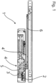
- FIG 1 is a schematic sectional view of an electromechanical drive 1 for actuating a wing, in particular a door wing or a window wing, which is mounted rotatably and/or displaceably on a structural element.
- the electromechanical drive 1 has a three-phase three-phase motor 2, which is designed as an axial flow machine.
- a drive shaft 3 of the three-phase motor 2 is operatively connected to the wing (not shown) via a power transmission device 4.
- the power transmission device 4 essentially consists of a gear 5 connected to the three-phase motor 2 and a lever 6. This converts a movement of the drive shaft 3 in motor mode of the three-phase motor 2 into a movement of the wing.
- a movement of the wing in generator mode of the three-phase motor 2 causes a movement of the drive shaft 3 via the power transmission device 4.
- the electromechanical drive 1 also has a Figure 1 not recognizable but in Figure 2 The emergency braking device 7 is shown in detail.
- the emergency braking device 7 can be used to brake the movement of the wing in an operating state suitable for emergencies by operating the three-phase motor 2 as a generator. As a result of the movement of the wing, a movement-dependent voltage is applied between phase terminals 8 of the three-phase motor 2 operated as a generator. The phase terminals 8 are electrically connected to a braking circuit 9 of the emergency braking device 7.
- the emergency braking device 7 has a control energy generating device 10.
- the control energy generating device 10 generates electrical energy for operating a control device 11 of the emergency braking device 7, which controls the braking circuit 9, from an electrical current flowing between the phase terminals 8.
- the control energy generating device 10 is electrically connected to the control device 11.
- the braking circuit 9 has a current control device 12, by means of which a current flow through the braking circuit 9 and thus between the phase terminals 8 can be adjusted.
- the control device 11 is electrically connected to the current control device 12 in order to specify the braking effect exerted on the wing by the emergency braking device 7.
- the braking circuit 9 also has a brake rectifier circuit 13 designed as a bridge rectifier circuit.
- the brake rectifier circuit 13 is electrically connected to the phase terminals 8 of the three-phase motor 2 operated as a generator.
- the control energy generation device 10 has a control rectifier circuit 14 which is also designed as a bridge rectifier circuit.
- the control rectifier circuit 14 is also electrically connected to the phase terminals 8 of the three-phase motor 2 operated as a generator in parallel to the brake rectifier circuit 13.
- the control device 11 has a central control unit 15.
- the central control unit 15 is a microcontroller.
- the current control device 12 comprises a transistor 16 designed as a MOSFET, a current measuring element 17 designed as a shunt resistor and a control element 18 designed as an operational amplifier.
- the transistor 16 is electrically connected to the brake rectifier circuit 13 via a collector and an emitter.
- the control element 18 is electrically connected to a base of the transistor 16 in order to specify the current flow through the transistor 16.
- the control element 18 is also electrically connected to the central control unit 15 of the control device 11.
- the control device 11 specifies a current setpoint value for the control element 18.
- the control element 18 is also electrically connected to the current measuring element 17.
- the current measuring element 17 measures a current flowing through the transistor 16.
- the control element 18 limits a current flow between the phase terminals 8 so that the current setpoint and the current flow match.
- a level converter 19 is arranged between the central control unit 15 and the control element 18.
- the control device 11 also has an overvoltage protection 20, which is directly electrically connected to the control energy generation device 10.
- the control device 13 also has a voltage regulator 21 and a linear regulator 22, which are electrically connected to the current control device 12 and supply the current control device 12 with electrical energy.
- the control device 11 also has a measuring device 23 to record the speed and direction of movement of the wing.
Abstract
Die Erfindung betrifft einen elektromechanischen Antrieb (1) zum Betätigen eines beweglich an einem Strukturelement gelagerten Flügels, insbesondere eines Türflügels oder eines Fensterflügels. Der elektromechanische Antrieb (1) weist einen Elektromotor (2) mit mindestens einer Phase auf, Ein Spannungsverlauf über diese Phase ist im Betrieb des Elektromotors (2) kontinuierlich. Eine Antriebswelle (3) des Elektromotors (2) steht über eine Kraftübertragungseinrichtung (4) mit dem Flügel in Wirkverbindung, wenn der elektromechanische Antrieb (1) bestimmungsgemäß an dem Flügel und/oder der Zarge montiert ist, so dass eine Bewegung der Antriebswelle (3) eine Bewegung des Flügels bewirkt. Der elektromechanische Antrieb (1) weist einen mechanischen Energiespeicher auf, welcher durch eine Öffnungsbewegung des Flügels aufgeladen und durch eine Schließbewegung des Flügels entladen wird, sodass die Schließbewegung durch die in dem mechanischen Energiespeicher gespeicherte Energie ausgelöst und/oder unterstützt wird. Der elektromechanische Antrieb (1) weist eine Notfallbremseinrichtung auf, durch welche die Bewegung des Flügels in einem für Notfälle geeigneten Betriebszustand bremsbar ist.The invention relates to an electromechanical drive (1) for actuating a wing movably mounted on a structural element, in particular a door wing or a window wing. The electromechanical drive (1) has an electric motor (2) with at least one phase. A voltage curve over this phase is continuous when the electric motor (2) is in operation. A drive shaft (3) of the electric motor (2) is operatively connected to the wing via a power transmission device (4) when the electromechanical drive (1) is mounted as intended on the wing and/or the frame, so that a movement of the drive shaft (3) causes a movement of the wing. The electromechanical drive (1) has a mechanical energy store which is charged by an opening movement of the wing and discharged by a closing movement of the wing, so that the closing movement is triggered and/or supported by the energy stored in the mechanical energy store. The electromechanical drive (1) has an emergency braking device by which the movement of the wing can be braked in an operating state suitable for emergencies.
Description
Die Erfindung betrifft einen elektromechanischen Antrieb zum Betätigen eines beweglich an einem Strukturelement gelagerten Flügels, insbesondere eines Türflügels oder eines Fensterflügels, wobei der elektromechanische Antrieb einen Elektromotor mit mindestens einer Phase aufweist, wobei ein Spannungsverlauf über diese Phase im Betrieb des Elektromotors kontinuierlich ist, wobei eine Antriebswelle des Elektromotors über eine Kraftübertragungseinrichtung mit dem Flügel in Wirkverbindung steht, wenn der elektromechanische Antrieb bestimmungsgemäß an dem Flügel und/oder der Zarge montiert ist, so dass eine Bewegung der Antriebswelle eine Bewegung des Flügels bewirkt, wobei der elektromechanische Antrieb einen mechanischen Energiespeicher aufweist, welcher durch eine Öffnungsbewegung des Flügels aufgeladen und durch eine Schließbewegung des Flügels entladen wird, sodass die Schließbewegung durch die in dem mechanischen Energiespeicher gespeicherte Energie ausgelöst und/oder unterstützt wird.The invention relates to an electromechanical drive for actuating a wing movably mounted on a structural element, in particular a door wing or a window wing, wherein the electromechanical drive has an electric motor with at least one phase, wherein a voltage curve over this phase is continuous during operation of the electric motor, wherein a drive shaft of the electric motor is operatively connected to the wing via a power transmission device when the electromechanical drive is mounted as intended on the wing and/or the frame, so that a movement of the drive shaft causes a movement of the wing, wherein the electromechanical drive has a mechanical energy store which is charged by an opening movement of the wing and discharged by a closing movement of the wing, so that the closing movement is triggered and/or supported by the energy stored in the mechanical energy store.
Aus dem Stand der Technik sind elektromechanische Antriebe zum Bewegen eines Flügels bekannt. Unter einem Flügel wird dabei insbesondere ein Tür- oder Fensterflügel verstanden. Derartige Flügel sind in den, den Flügel umgebenden Strukturelementen wie beispielsweise Zargen gelagert. Der Flügel stellt also den beweglichen Teil und das Strukturelement den feststehenden Teil dar. Mit dem Begriff der Zarge kann somit auch jedes andere den Flügel umgebende Strukturelement gemeint sein, insbesondere eine Gebäudewand.Electromechanical drives for moving a wing are known from the state of the art. A wing is understood to mean a door or window wing in particular. Such wings are mounted in the structural elements surrounding the wing, such as frames. The wing is therefore the moving part and the structural element is the fixed part. The term frame can therefore also refer to any other structural element surrounding the wing, in particular a building wall.
Derartige elektromechanische Antriebe weisen häufig einen Elektromotor sowie eine mechanische Schließeinheit auf. Bei der mechanischen Schließeinheit kann es sich beispielsweise um eine Feder handeln, die beim Öffnen des Flügels bzw. beim Bewegen des Flügels in eine Öffnungsrichtung durch den Elektromotor gespannt wird. Zum Schließen des Flügels wird die in der Feder gespeicherte Energie verwendet. Während des Schließvorgangs kann der Elektromotor zum Abbremsen der Flügelbewegung verwendet werden.Such electromechanical drives often have an electric motor and a mechanical locking unit. The mechanical locking unit can be, for example, a spring that is tensioned by the electric motor when the wing is opened or when the wing is moved in an opening direction. The energy stored in the spring is used to close the wing. used. During the closing process, the electric motor can be used to slow down the wing movement.
Auch im Fehlerfall und insbesondere bei einem Stromausfall soll der Flügel zuverlässig abgebremst werden. Dies betrifft nicht nur den Schließvorgang, sondern im Fehlerfall auch den manuell ausgeführten Öffnungsvorgang, um ein unkontrolliertes Anschlagen in die Öffnungsendlage zu vermeiden.Even in the event of a fault, and especially in the event of a power failure, the sash should be reliably braked. This applies not only to the closing process, but also to the manual opening process in the event of a fault, in order to avoid an uncontrolled impact in the opening end position.
Um im Fehlerfall den Elektromotor zum Abbremsen verwenden zu können ist es bekannt, Phasen des Elektromotors beispielsweise über Dioden kurzzuschließen. Dreht sich der Elektromotor mit kurzgeschlossener Phase, so wird eine Spannung induziert, wobei der über die Phase fließende Strom ein Bremsmoment bewirkt. Auf diese Weise kann der Elektromotor im Generatorbetrieb als Bremse verwendet werden. Aus der Druckschrift
Zur Steuerung der Bremswirkung im Fehlerfall ist es erforderlich, elektrische Energie für den Betrieb der Steuerelektronik bereitzustellen. Dies kann beispielsweise durch geeignete Batterien erfolgen. Dabei muss jedoch stets überwacht werden, dass die Batterien eine ausreichende Ladung aufweisen, um den Betrieb der Steuerelektronik zu ermöglichen. Zudem kann auf diese Weise ein längerer Betrieb im Fehlerfall nicht sichergestellt werden, da die Batterien nur eine begrenzte Kapazität aufweisen.In order to control the braking effect in the event of a fault, it is necessary to provide electrical energy to operate the control electronics. This can be done using suitable batteries, for example. However, it must always be monitored that the batteries have sufficient charge to enable the control electronics to operate. In addition, this method cannot ensure longer operation in the event of a fault, as the batteries only have a limited capacity.
Als Aufgabe der Erfindung wird es angesehen, die aus dem Stand der Technik bekannten elektromechanischen Antriebe so weiterzuentwickeln, dass ein sicherer Betrieb im Fehlerfall möglich ist.The object of the invention is to further develop the electromechanical drives known from the prior art in such a way that safe operation is possible in the event of a fault.
Diese Aufgabe wird erfindungsgemäß dadurch gelöst, dass der elektromechanische Antrieb eine Notfallbremsvorrichtung aufweist, durch welche die Bewegung des Flügels in einem für Notfälle geeigneten Betriebszustand bremsbar ist, indem der Elektromotor als Generator betrieben wird, wobei durch die Bewegung des Flügels zwischen Phasenklemmen des als Generator betriebenen Elektromotors jeweils eine bewegungsabhängige Spannung anliegt, wobei die Phasenklemmen elektrisch leitend mit einem Bremsstromkreis der Notfallbremseinrichtung verbunden sind, wobei die Notfallbremseinrichtung eine Steuerenergieerzeugungseinrichtung aufweist, wobei die Steuerenergieerzeugungseinrichtung elektrische Energie für den Betrieb einer den Bremsstromkreis steuernden Steuereinrichtung der Notfallbremseinrichtung aus einem zwischen den Phasenklemmen fließenden elektrischen Strom erzeugt, wobei die Steuerenergieerzeugungseinrichtung elektrisch leitend mit der Steuereinrichtung verbunden ist, wobei der Bremsstromkreis eine Stromsteuereinrichtung aufweist, durch die ein Stromfluss durch den Bremsstromkreis und dadurch zwischen den Phasenklemmen anpassbar ist, und wobei die Steuereinrichtung elektrisch leitend mit der Stromsteuereinrichtung verbunden ist, um die von der Notfallbremseinrichtung auf den Flügel ausgeübte Bremswirkung vorzugeben. Die Notfallbremsvorrichtung ist dabei so ausgestaltet, dass insbesondere bei einem Stromausfall aus der durch die Bewegung des Flügels generatorisch erzeugten elektrischen Energie die Steuereinrichtung mit elektrischer Energie versorgt wird. Auf diese Weise kann die Steuereinrichtung bei einer Bewegung des Flügels die Stromsteuereinrichtung des Bremsstromkreises so ansteuern, dass eine gewünschte maximale Bremswirkung durch eine Anpassung des zwischen den Phasenklemmen des Elektromotors fließenden Stroms erreicht wird. Bewegt sich der Flügel nicht, liegt keine Spannung zwischen den Phasenklemmen an, so dass die Stromerzeugungseinrichtung keine elektrische Energie für den Betrieb der Steuereinrichtung bereitstellen kann und die Steuereinrichtung nicht betrieben werden kann. Da die Steuereinrichtung nur für den kontrollierten Bremsvorgang vorgesehen und erforderlich ist, ist dies jedoch kein Nachteil.This object is achieved according to the invention in that the electromechanical drive has an emergency braking device by means of which the movement of the wing can be braked in an operating state suitable for emergencies by operating the electric motor as a generator, wherein the movement of the wing causes a movement-dependent voltage to be applied between phase terminals of the electric motor operated as a generator, wherein the phase terminals are electrically connected to a braking circuit of the emergency braking device, wherein the emergency braking device has a control energy generating device, wherein the control energy generating device generates electrical energy for operating a control device of the emergency braking device that controls the braking circuit from an electrical current flowing between the phase terminals, wherein the control energy generating device is electrically connected to the control device, wherein the braking circuit has a current control device by means of which a current flow through the braking circuit and thereby between the phase terminals can be adjusted, and wherein the control device is electrically connected to the current control device in order to specify the braking effect exerted on the wing by the emergency braking device. The emergency braking device is designed in such a way that, in particular in the event of a power failure, the control device is supplied with electrical energy from the electrical energy generated by the movement of the wing. In this way, when the wing moves, the control device can control the current control device of the braking circuit in such a way that a desired maximum braking effect is achieved by adjusting the current flowing between the phase terminals of the electric motor. If the wing does not move, there is no voltage between the phase terminals, so that the power generation device cannot provide electrical energy to operate the control device and the control device cannot be operated. However, since the control device is only intended and required for the controlled braking process, this is not a disadvantage.
Erfindungsgemäß ist vorteilhafterweise vorgesehen, dass es sich bei dem Elektromotor um einen Drehstrom- oder Wechselstromelektromotor handelt, wobei der Bremsstromkreis eine Bremsgleichrichterschaltung aufweist, wobei die Bremsgleichrichterschaltung mit den Phasenklemmen des als Generator betriebenen Elektromotors elektrisch leitend verbunden ist. Im Generatorbetrieb erzeugt der Wechsel- oder Drehstromelektromotor eine ein- oder mehrphasige elektrische Wechselspannung zwischen den einander zugeordneten Phasenklemmen des Elektromotors. Durch die Gleichrichtung dieser gegebenenfalls mehrphasigen Wechselspannung durch die Bremsgleichrichterschaltung kann der über den Bremsstromkreis zwischen den Phasenklemmen fließende Brems- bzw. Kurzschlussstrom besonders einfach beispielsweise durch die erfindungsgemäße Verwendung eines MOSFETs im Bremsstromkreis angepasst werden.According to the invention, it is advantageously provided that the electric motor is a three-phase or alternating current electric motor, wherein the braking circuit has a braking rectifier circuit, wherein the braking rectifier circuit is electrically connected to the phase terminals of the electric motor operated as a generator. In generator mode, the alternating current or three-phase electric motor generates a single-phase or multi-phase electrical alternating voltage between the mutually associated phase terminals of the electric motor. By rectifying this possibly multi-phase alternating voltage by the braking rectifier circuit, the braking or short-circuit current flowing via the braking circuit between the phase terminals can be adjusted particularly easily, for example by using a MOSFET in the braking circuit according to the invention.
Vorteilhafterweise ist erfindungsgemäß vorgesehen, dass die Steuerenergieerzeugungseinrichtung eine Steuergleichrichterschaltung aufweist, wobei die Steuergleichrichterschaltung mit den Phasenklemmen des als Generator betriebenen Elektromotors elektrisch leitend verbunden ist. Die elektrische Energie für den Betrieb der Steuereinrichtung kann besonders einfach direkt über die Steuergleichrichterschaltung aus der zwischen den Phasenklemmen anliegenden elektrischen Spannung erzeugt werden. Für den Betrieb der Steuereinrichtung ist eine elektrische Gleichspannung vorteilhaft, da hiermit herkömmliche elektronische Schaltungselemente wie beispielsweise Mikrocontroller betrieben werden können. Da durch die Steuergleichrichterschaltung die zwischen den Phasenklemmen anliegende Wechselspannung gleichgerichtet wird, kann die durch die Steuergleichrichterschaltung bereitgestellte elektrische Energie direkt weiteren elektronischen Schaltungskomponenten zur Verfügung gestellt werden. Bei Verwendung eines Gleichstrommotors ist die Steuergleichrichterschaltung so ausgestaltet, dass eine von einer Bewegungsrichtung des Flügels abhängige Spannungspolarität der bewegungsabhängigen Spannung zwischen den Phasenklemmen zum Betrieb der Steuereinrichtung gleichgerichtet wird.Advantageously, the invention provides that the control energy generating device has a control rectifier circuit, wherein the control rectifier circuit is electrically connected to the phase terminals of the electric motor operated as a generator. The electrical energy for operating the control device can be generated particularly easily directly via the control rectifier circuit from the electrical voltage present between the phase terminals. A direct current is advantageous for operating the control device, since this can be used to operate conventional electronic circuit elements such as microcontrollers. Since the control rectifier circuit rectifies the alternating voltage present between the phase terminals, the electrical energy provided by the control rectifier circuit can be made available directly to other electronic circuit components. When using a direct current motor, the control rectifier circuit is designed such that a voltage polarity of the movement-dependent voltage between the phase terminals, which depends on a direction of movement of the wing, is rectified to operate the control device.
Vorteilhafterweise ist erfindungsgemäß vorgesehen, dass die Steuergleichrichterschaltung und die Bremsgleichrichterschaltung parallel zueinander mit den Phasenklemmen elektrisch leitend verbunden sind. Durch die Verwendung der Bremsgleichrichterschaltung und der Steuergleichrichterschaltung können die jeweiligen Vorteile miteinander kombiniert werden. Bei der Ausgestaltung der Bremsgleichrichterschaltung und der Steuergleichrichterschaltung muss lediglich sichergestellt werden, dass in jedem Betriebszustand des Bremsstromkreises der Steuereinrichtung ausreichend elektrische Energie durch die Steuergleichrichterschaltung zur Verfügung gestellt werden kann.Advantageously, the invention provides that the control rectifier circuit and the brake rectifier circuit are electrically connected in parallel to one another with the phase terminals. By using the brake rectifier circuit and the control rectifier circuit, the respective advantages can be combined with one another. When designing the brake rectifier circuit and the control rectifier circuit, it is only necessary to ensure that sufficient electrical energy can be made available by the control rectifier circuit in every operating state of the brake circuit of the control device.
Ein besonders einfacher Aufbau der Bremsgleichrichterschaltung oder der Steuergleichrichterschaltung kann dadurch erreicht werden, dass die Steuergleichrichterschaltung und/oder die Bremsgleichrichterschaltung als Brückengleichrichterschaltung ausgestaltet sind. Die Brückengleichrichterschaltung wird auch als Zweipuls-Brücken-Gleichrichterschaltung bezeichnet und weist zwei parallel geschaltete Diodenpaare auf. Die Phasenklemmen sind zwischen den Diodenpaaren mit der Brückengleichrichterschaltung elektrisch leitend verbunden.A particularly simple structure of the brake rectifier circuit or the control rectifier circuit can be achieved by designing the control rectifier circuit and/or the brake rectifier circuit as a bridge rectifier circuit. The bridge rectifier circuit is also referred to as a two-pulse bridge rectifier circuit and has two pairs of diodes connected in parallel. The phase terminals are electrically connected between the pairs of diodes to the bridge rectifier circuit.
Um zu erreichen, dass in jedem Betriebszustand des Bremsstromkreises der Steuereinrichtung ausreichend elektrische Energie durch die Steuergleichrichterschaltung zur Verfügung gestellt werden kann, ist erfindungsgemäß vorgesehen, dass ein Aufbau der Steuergleichrichterschaltung und ein Aufbau der Bremsgleichrichterschaltung gleich sind. "Gleich" bedeutet in diesem Zusammenhang, dass ein identischer Aufbau der Gleichrichterschaltungen mit Bauteilen gewählt wird, die eine zumindest sehr ähnliche Charakteristik aufweisen. Sofern Brückengleichrichterschaltungen verwendet werden, sollten die jeweils eingesetzten Dioden möglichst ähnliche Eigenschaften aufweisen.In order to ensure that sufficient electrical energy can be made available by the control rectifier circuit in every operating state of the brake circuit of the control device, the invention provides that the structure of the control rectifier circuit and the structure of the brake rectifier circuit are identical. "Identical" in this context means that an identical structure of the rectifier circuits is selected with components that have at least very similar characteristics. If bridge rectifier circuits are used, the diodes used should have properties that are as similar as possible.
Eine maximale Bremswirkung durch den Elektromotor wird erreicht, wenn der zwischen den Phasenklemmen fließende Bremsstrom durch die Stromsteuereinrichtung nicht begrenzt wird. Dies entspricht einem harten Phasenkurzschluss. Eine Ausgangsspannung über die Bremsgleichrichterschaltung beträgt in diesem Fall etwa 0V. Bei Verwendung von beispielsweise Brückengleichrichtern ist in diesem Fall ein Spannungsabfall über den Dioden der Bremsgleichrichterschaltung durch den hohen Bremsstrom relativ groß. Werden für die Steuergleichrichterschaltung Dioden mit einer ähnlichen Charakteristik wie für die Bremsgleichrichterschaltung verwendet, und ist der durch die Steuereinrichtung fließende Strom geringer als der durch die Bremsgleichrichterschaltung fließende Bremsstrom, so ist der Spannungsabfall über die Dioden der Steuergleichrichterschaltung ebenfalls geringer. Diese Spannungsdifferenz ist als Ausgangsspannung der Steuergleichrichterschaltung für die Steuereinrichtung nutzbar.A maximum braking effect by the electric motor is achieved if the braking current flowing between the phase terminals is not limited by the current control device. This corresponds to a hard Phase short circuit. In this case, an output voltage across the brake rectifier circuit is approximately 0V. When using bridge rectifiers, for example, the voltage drop across the diodes of the brake rectifier circuit is relatively large due to the high braking current. If diodes with a similar characteristic to the brake rectifier circuit are used for the control rectifier circuit and the current flowing through the control device is lower than the braking current flowing through the brake rectifier circuit, the voltage drop across the diodes of the control rectifier circuit is also lower. This voltage difference can be used as the output voltage of the control rectifier circuit for the control device.
Alternativ oder in Ergänzung zur Verwendung einer Steuergleichrichterschaltung ist vorteilhafterweise vorgesehen, dass die Steuerenergieerzeugungseinrichtung ein Spannungsabfallelement aufweist, wobei das Spannungsabfallelement elektrisch leitend mit der Bremsgleichrichterschaltung und der Stromsteuereinrichtung verbunden ist, wobei die Steuereinrichtung parallel zu dem Spannungsabfallelement elektrisch leitend mit der Bremsgleichrichterschaltung und der Stromsteuereinrichtung verbunden ist. Bei dem Spannungsabfallelement kann es sich beispielsweise um ein Ohm'sches-Widerstandselement mit einem vorgegebenen elektrischen Widerstand handeln, dass in Reihe mit der Bremsgleichrichterschaltung und der Stromsteuereinrichtung geschaltet ist. Sobald Strom über die Stromsteuereinrichtung fließt, fällt über das Widerstandselement eine stromabhängige, definierte Spannung ab, die für die Versorgung der Steuereinrichtung verwendet werden kann.Alternatively or in addition to the use of a control rectifier circuit, it is advantageously provided that the control energy generation device has a voltage drop element, wherein the voltage drop element is electrically connected to the brake rectifier circuit and the current control device, wherein the control device is electrically connected to the brake rectifier circuit and the current control device in parallel to the voltage drop element. The voltage drop element can, for example, be an ohmic resistance element with a predetermined electrical resistance that is connected in series with the brake rectifier circuit and the current control device. As soon as current flows through the current control device, a current-dependent, defined voltage drops across the resistance element, which can be used to supply the control device.
Vorteilhafterweise ist erfindungsgemäß vorgesehen, dass die Steuerenergieerzeugungseinrichtung elektrisch leitend mit der Stromsteuereinrichtung in einer Parallelschaltung verbunden ist. Je nach Ausgestaltung der Stromsteuereinrichtung beinhaltet die Stromsteuereinrichtung bereits elektrische Elemente, über die ein Spannungsabfall erzeugt wird, der für den Betrieb der Steuereinrichtung genutzt werden kann. Beispielsweise kann in der Stromsteuereinrichtung vorteilhafterweise ein Strommesswiderstand vorgesehen sein, der zusätzlich auch als Spannungsabfallelement genutzt werden kann.Advantageously, the invention provides that the control energy generation device is electrically connected to the current control device in a parallel circuit. Depending on the design of the current control device, the current control device already contains electrical elements via which a voltage drop is generated that can be used to operate the control device. For example, in the A current measuring resistor can advantageously be provided in the current control device, which can also be used as a voltage drop element.
Um die Steuereinrichtung jederzeit mit ausreichender elektrischer Energie versorgen zu können und damit die Stromsteuereinrichtung ansteuern zu können, ist bei Verwendung eines Spannungsabfallelements vorteilhafterweise vorgesehen, dass die Stromsteuereinrichtung so ausgestaltet ist, dass ein Stromfluss über die Bremsgleichrichterschaltung und die Stromsteuereinrichtung bei einer Bewegung des Flügels jederzeit größer als ein Stromflussminimum ist. Dadurch fließt durch den Bremsstromkreis bei einer Bewegung des Flügels jederzeit ein elektrischer Strom durch den über das Spannungsabfallelement ausreichend Energie zum Betrieb der Steuereinrichtung bereitgestellt werden kann.In order to be able to supply the control device with sufficient electrical energy at all times and thus to be able to control the current control device, it is advantageous when using a voltage drop element that the current control device is designed in such a way that a current flow through the brake rectifier circuit and the current control device is always greater than a current flow minimum when the wing moves. As a result, an electrical current flows through the brake circuit at all times when the wing moves, through which sufficient energy can be provided to operate the control device via the voltage drop element.
Vorteilhafterweise ist erfindungsgemäß vorgesehen, dass die Steuereinrichtung eine zentrale Steuereinheit aufweist. Bei der zentralen Steuereinheit handelt es sich vorteilhafterweise um eine elektronische und besonders vorteilhafterweise um eine digital-elektronische Datenverarbeitungseinrichtung. Erfindungsgemäß wird als zentrale Steuereinrichtung vorteilhafterweise ein Mikrocontroller verwendet. Mikrocontroller bieten elektrische Ein- und Ausgänge mit Digital-Analog- und Analog-Digital-Wandlern, PWM-Ausgänge und Komparator-Eingänge an, sodass mit einem Mikrocontroller gleichzeitig die erforderlichen Berechnungen durchgeführt, die elektrischen Signale für die Ansteuerung der Stromsteuereinrichtung erzeugt und Messignale verarbeitet werden können.Advantageously, the invention provides that the control device has a central control unit. The central control unit is advantageously an electronic and particularly advantageously a digital-electronic data processing device. According to the invention, a microcontroller is advantageously used as the central control device. Microcontrollers offer electrical inputs and outputs with digital-analog and analog-digital converters, PWM outputs and comparator inputs, so that the necessary calculations can be carried out, the electrical signals for controlling the current control device can be generated and measurement signals can be processed simultaneously with a microcontroller.
Vorteilhafterweise ist erfindungsgemäß vorgesehen, dass die Stromsteuereinrichtung einen Transistor, ein Strommesselement und ein Regelelement umfasst, wobei der Transistor über einen Kollektor und einen Emitter mit der Bremsgleichrichterschaltung elektrisch leitend verbunden ist, wobei durch das Strommesselement ein durch den Transistor fließender Strom gemessen wird, und wobei das Regelelement elektrisch leitend mit einer Basis des Transistors verbunden ist, um den Stromfluss durch den Transistor vorzugeben, wobei das Regelelement elektrisch leitend mit der zentralen Steuereinheit der Steuereinrichtung verbunden ist, wobei die Steuereinrichtung dem Regelelement einen Stromsollwert vorgibt, wobei das Regelelement elektrisch leitend mit dem Strommesselement verbunden ist, wobei das Regelelement einen Stromfluss so begrenzt, dass der Stromsollwert und der Strom übereinstimmen.Advantageously, the invention provides that the current control device comprises a transistor, a current measuring element and a control element, wherein the transistor is electrically connected to the brake rectifier circuit via a collector and an emitter, wherein a current flowing through the transistor is measured by the current measuring element, and wherein the control element is electrically connected to a base of the transistor in order to specify the current flow through the transistor, wherein the control element is electrically connected to the central control unit of the Control device is connected, wherein the control device specifies a current setpoint to the control element, wherein the control element is electrically conductively connected to the current measuring element, wherein the control element limits a current flow such that the current setpoint and the current match.
Bei dem Transistor handelt es sich vorteilhafterweise um ein MOSFET. Als Strommesselement kann vorteilhafterweise ein Shunt-Widerstand verwendet werden. Als Regelelement kann vorteilhafterweise ein Operationsverstärker verwendet werden. Durch den Operationsverstärker wird der durch den MOSFET und den Shunt-Widerstand fließende Stromwert mit einem von der Steuereinrichtung vorgegebenen Stromsollwert verglichen. Ist der fließende Strom zu groß, so wird die Gate-Spannung des MOSFETS durch den Operationsverstärker verringert, bis der Stromsollwert erreicht wird. Ist der fließende Strom zu klein, so wird die Gate-Spannung des MOSFETS durch den Operationsverstärker vergrößert, bis der Stromsollwert erreicht wird. Der MOSFET wird daher im Linearbetrieb verwendet. Durch diese Schaltung wird ein konstanter Laststrom zwischen den Phasenklemmen erzeugt, sofern der Elektromotor diesen liefern kann. Andernfalls wird der Laststrom durch den maximal von dem Elektromotor erzeugbaren Stromfluss begrenzt.The transistor is advantageously a MOSFET. A shunt resistor can advantageously be used as the current measuring element. An operational amplifier can advantageously be used as the control element. The operational amplifier compares the current value flowing through the MOSFET and the shunt resistor with a current setpoint specified by the control device. If the current flowing is too high, the gate voltage of the MOSFET is reduced by the operational amplifier until the current setpoint is reached. If the current flowing is too small, the gate voltage of the MOSFET is increased by the operational amplifier until the current setpoint is reached. The MOSFET is therefore used in linear operation. This circuit generates a constant load current between the phase terminals, provided the electric motor can supply it. Otherwise, the load current is limited by the maximum current flow that the electric motor can generate.
Vorteilhafterweise ist erfindungsgemäß vorgesehen, dass zwischen der zentralen Steuereinheit und dem Regelelement ein Pegelwandler angeordnet ist.Advantageously, the invention provides that a level converter is arranged between the central control unit and the control element.
Insbesondere bei Verwendung einer Steuergleichrichterschaltung entfernt sich mit zunehmendem Bremsstrom ein niedriges Potential der Bremsgleichrichterschaltung von einem für die Steuerung verwendeten Referenzpotential. Die Spannungsdifferenz zwischen diesen Potentialen kann die Stromsteuereinrichtung beeinflussen, sodass ohne einen zusätzlichen Schaltungsteil der effektive und von der Steuereinrichtung vorgegebene Stromsollwert bremsstromabhängig wäre und eine Reglung nicht möglich wäre. Durch den Pegelwandler kann der durch die Steuereinrichtung erzeugte Stromsollwert bzw. die zur Steuerung verwendete Stellspannung in eine differenzielle Ausgangsspannung umgewandelt werden, sodass die Stellspannung des Regelelements unabhängig von dem Bremsstrom ist.Particularly when using a control rectifier circuit, a low potential of the brake rectifier circuit moves away from a reference potential used for the control as the braking current increases. The voltage difference between these potentials can influence the current control device, so that without an additional circuit part the effective current setpoint specified by the control device would be dependent on the braking current and control would not be possible. The level converter can be used to convert the current setpoint generated by the control device or the reference potential used for control into a reference potential. Control voltage can be converted into a differential output voltage so that the control voltage of the control element is independent of the braking current.
Vorteilhafterweise ist erfindungsgemäß vorgesehen, dass die Steuereinrichtung einen Überspannungsschutz aufweist, wobei der Überspannungsschutz unmittelbar elektrisch leitend mit der Steuerenergieerzeugungseinrichtung verbunden ist. Beispielsweise könnte bei Verwendung einer Steuergleichrichterschaltung bei ungebremstem Elektromotor eine Ausgangsspannung der Steuergleichrichterschaltung der Leerlaufspannung des Elektromotors entsprechen. Diese Ausgangsspannung könnte je nach Ausgestaltung des Elektromotors für den Betrieb der Steuereinrichtung zu groß sein und diese beschädigen. Ein Überspannungsschutz bietet die Möglichkeit, die durch die Steuerenergieerzeugungseinrichtung erzeugte Ausgangsspannung in einem für den Betrieb der Steuereinrichtung sicheren Bereich zu begrenzen.Advantageously, the invention provides that the control device has overvoltage protection, wherein the overvoltage protection is directly electrically connected to the control energy generation device. For example, when using a control rectifier circuit with an unbraked electric motor, an output voltage of the control rectifier circuit could correspond to the no-load voltage of the electric motor. Depending on the design of the electric motor, this output voltage could be too high for the operation of the control device and could damage it. Overvoltage protection offers the possibility of limiting the output voltage generated by the control energy generation device to a range that is safe for the operation of the control device.
Vorteilhafterweise ist erfindungsgemäß vorgesehen, dass die Steuereinrichtung einen Spannungsregler aufweist, wobei der Spannungsregler elektrisch leitend mit der Stromsteuereinrichtung verbunden ist und die Stromsteuereinrichtung mit elektrischer Energie versorgt und wobei der Spannungsregler mit weiteren Komponenten der Steuereinrichtung elektrisch leitend verbunden ist und diese mit elektrischer Energie versorgt. Die beispielsweise mit einer Steuergleichrichterschaltung erzeugte Ausgangsspannung ist in vielen Anwendungsfällen für den Betrieb der Steuereinrichtung zu klein. Durch die Verwendung des Spannungsreglers, der beispielsweise als Schaltregler ausgestaltet sein kann, kann aus der Ausgangsspannung eine für den Betrieb der Steuereinrichtung ausreichende Betriebsspannung erzeugt werden.Advantageously, the invention provides that the control device has a voltage regulator, wherein the voltage regulator is electrically connected to the current control device and supplies the current control device with electrical energy, and wherein the voltage regulator is electrically connected to other components of the control device and supplies them with electrical energy. The output voltage generated, for example, with a control rectifier circuit is too small in many applications for the operation of the control device. By using the voltage regulator, which can be designed, for example, as a switching regulator, an operating voltage sufficient for the operation of the control device can be generated from the output voltage.
Um eine für den Betrieb der zentralen Steuereinheit ausreichend exakte Betriebsspannung zu erzeugen, ist erfindungsgemäß vorgesehen, dass die Steuereinrichtung einen Linearregler aufweist, wobei der Linearregler elektrisch leitend zwischen dem Spannungsregler und den weiteren Komponenten der Steuereinrichtung angeordnet ist.In order to generate an operating voltage that is sufficiently precise for the operation of the central control unit, the invention provides that the control device has a linear regulator, wherein the linear regulator is arranged in an electrically conductive manner between the voltage regulator and the other components of the control device.
Vorteilhafterweise ist erfindungsgemäß vorgesehen, dass die Steuereinrichtung eine Messeinrichtung zur Erfassung der Bewegungsgeschwindigkeit und der Bewegungsrichtung des Flügels aufweist. Die Messeinrichtung kann vorteilhafterweise Hall-Sensoren zur Erfassung von Drehbewegungsparametern des Elektromotors umfassen. Diese können vorteilhafterweise durch die zentrale Steuereinrichtung verarbeitet werden. Bei der Verwendung eines Mikrocontrollers als zentrale Steuerungseinrichtung können zu diesem Zweck die vorhandenen Eingänge des Mikrocontrollers verwendet werden.Advantageously, the invention provides that the control device has a measuring device for detecting the speed and direction of movement of the wing. The measuring device can advantageously comprise Hall sensors for detecting rotational movement parameters of the electric motor. These can advantageously be processed by the central control device. When using a microcontroller as the central control device, the existing inputs of the microcontroller can be used for this purpose.
Vorteilhafterweise ist erfindungsgemäß vorgesehen, dass es sich bei dem Elektromotor um einen Axialflussmotor oder einen Radialflussmotor handelt. Axial- oder Radialflussmaschinen eignen sich besonders gut für die Verwendung mit Tür- oder Fensterantrieben.Advantageously, the invention provides that the electric motor is an axial flux motor or a radial flux motor. Axial or radial flux machines are particularly suitable for use with door or window drives.
Bei einer besonders vorteilhaften Ausgestaltung des erfindungsgemäßen elektromechanischen Antriebs ist vorgesehen, dass der elektromechanische Antrieb aus dem Drehstrommotor und der Notfallbremsvorrichtung besteht, wobei die Notfallbremsvorrichtung aus der Steuerenergieerzeugungseinrichtung, der Steuereinrichtung und dem Bremsstromkreis besteht, wobei die Steuerenergieerzeugungseinrichtung aus der Steuergleichrichterschaltung besteht, wobei die Steuereinrichtung aus dem Regelelement, dem Pegelwandler, dem Überspannungsschutz, dem Spannungsregler, dem Linearregler, der Messeinrichtung und der zentralen Steuereinheit besteht, wobei der Bremsstromkreis aus der Stromsteuereinrichtung und dem Bremsgleichrichterschaltung besteht, und wobei die Stromsteuereinrichtung aus dem Transistor, dem Strommesselement und dem Regelelement besteht.In a particularly advantageous embodiment of the electromechanical drive according to the invention, it is provided that the electromechanical drive consists of the three-phase motor and the emergency braking device, wherein the emergency braking device consists of the control energy generating device, the control device and the braking circuit, wherein the control energy generating device consists of the control rectifier circuit, wherein the control device consists of the control element, the level converter, the overvoltage protection, the voltage regulator, the linear regulator, the measuring device and the central control unit, wherein the braking circuit consists of the current control device and the braking rectifier circuit, and wherein the current control device consists of the transistor, the current measuring element and the control element.
Weitere vorteilhafte Ausgestaltungen des erfindungsgemäßen elektromechanischen Antriebs werden anhand von in der Zeichnung dargestellten Ausführungsbeispielen näher erläutert.Further advantageous embodiments of the electromechanical drive according to the invention are explained in more detail with reference to embodiments shown in the drawing.
Es zeigt:
-
Figur 1 eine schematisch dargestellte Schnittansicht eines elektromechanischen Antriebs mit einer Notfallbremsvorrichtung und -
Figur 2
-
Figure 1 a schematic sectional view of an electromechanical drive with an emergency braking device and -
Figure 2 a circuit diagram of the emergency braking device.
In
Durch die Notfallbremsvorrichtung 7 ist die Bewegung des Flügels in einem für Notfälle geeigneten Betriebszustand bremsbar, indem der Drehstrommotor 2 als Generator betrieben wird. Durch die Bewegung des Flügels liegt zwischen Phasenklemmen 8 des als Generator betriebenen Drehstrommotors 2 jeweils eine bewegungsabhängige Spannung an. Die Phasenklemmen 8 sind elektrisch leitend mit einem Bremsstromkreis 9 der Notfallbremseinrichtung 7 verbunden.The
Die Notfallbremsvorrichtung 7 weist eine Steuerenergieerzeugungseinrichtung 10 auf. Die Steuerenergieerzeugungseinrichtung 10 erzeugt elektrische Energie für den Betrieb einer den Bremsstromkreis 9 steuernden Steuereinrichtung 11 der Notfallbremseinrichtung 7 aus einem zwischen den Phasenklemmen 8 fließenden elektrischen Strom. Die Steuerenergieerzeugungseinrichtung 10 ist elektrisch leitend mit der Steuereinrichtung 11 verbunden.The
Der Bremsstromkreis 9 weist eine Stromsteuereinrichtung 12 auf, durch die ein Stromfluss durch den Bremsstromkreis 9 und dadurch zwischen den Phasenklemmen 8 anpassbar ist. Die Steuereinrichtung 11 ist elektrisch leitend mit der Stromsteuereinrichtung 12 verbunden, um die von der Notfallbremseinrichtung 7 auf den Flügel ausgeübte Bremswirkung vorzugeben. Der Bremsstromkreis 9 weist zudem eine als Brückengleichrichterschaltung ausgestaltete Bremsgleichrichterschaltung 13 auf. Die Bremsgleichrichterschaltung 13 ist mit den Phasenklemmen 8 des als Generator betriebenen Drehstrommotors 2 elektrisch leitend verbunden.The
Die Steuerenergieerzeugungseinrichtung 10 weist eine ebenfalls als Brückengleichrichterschaltung ausgestaltete Steuergleichrichterschaltung 14 auf. Die Steuergleichrichterschaltung 14 ist ebenfalls mit den Phasenklemmen 8 des als Generator betriebenen Drehstrommotors 2 parallel zu der Bremsgleichrichterschaltung 13 elektrisch leitend verbunden.The control
Die Steuereinrichtung 11 weist eine zentrale Steuereinheit 15 auf. Bei der zentralen Steuereinheit 15 handelt es sich um einen Mikrocontroller.The
Die Stromsteuereinrichtung 12 umfasst einen als MOSFET ausgestalteten Transistor 16, ein als Shunt-Widerstand ausgestaltetes Strommesselement 17 und ein als Operationsverstärker ausgestaltetes Regelelement 18. Der Transistor 16 ist über einen Kollektor und einen Emitter mit der Bremsgleichrichterschaltung 13 elektrisch leitend verbunden.The
Das Regelelement 18 ist elektrisch leitend mit einer Basis des Transistors 16 verbunden, um den Stromfluss durch den Transistor 16 vorzugeben. Das Regelelement 18 ist zudem elektrisch leitend mit der zentralen Steuereinheit 15 der Steuereinrichtung 11 verbunden. Die Steuereinrichtung 11 gibt dem Regelelement 18 einen Stromsollwert vor.The
Das Regelelement 18 ist zudem elektrisch leitend mit dem Strommesselement 17 verbunden. Durch das Strommesselement 17 wird ein durch den Transistor 16 fließender Strom gemessen. Das Regelelement 18 begrenzt einen Stromfluss zwischen den Phasenklemmen 8 so, dass der Stromsollwert und der Stromfluss übereinstimmen.The
Zwischen der zentralen Steuereinheit 15 und dem Regelelement 18 ein Pegelwandler 19 angeordnet ist. Die Steuereinrichtung 11 weist zudem einen Überspannungsschutz 20 auf, der unmittelbar elektrisch leitend mit der Steuerenergieerzeugungseinrichtung 10 verbunden ist. Die Steuereinrichtung 13 weist auch einen Spannungsregler 21 und einen Linearregler 22 auf, die elektrisch leitend mit der Stromsteuereinrichtung 12 verbunden sind und die Stromsteuereinrichtung 12 mit elektrischer Energie versorgen. Zur Erfassung der Bewegungsgeschwindigkeit und der Bewegungsrichtung des Flügels weist die Steuereinrichtung 11 zudem eine Messeinrichtung 23 auf.A
Claims (16)
Priority Applications (2)
| Application Number | Priority Date | Filing Date | Title |
|---|---|---|---|
| EP22200311.3A EP4350971A1 (en) | 2022-10-07 | 2022-10-07 | Electromechanical drive for actuating a leaf movably mounted on a structural element |
| PCT/EP2023/077635 WO2024074644A1 (en) | 2022-10-07 | 2023-10-05 | Electromechanical drive for actuating a sash mounted moveably on a structure element |
Applications Claiming Priority (1)
| Application Number | Priority Date | Filing Date | Title |
|---|---|---|---|
| EP22200311.3A EP4350971A1 (en) | 2022-10-07 | 2022-10-07 | Electromechanical drive for actuating a leaf movably mounted on a structural element |
Publications (1)
| Publication Number | Publication Date |
|---|---|
| EP4350971A1 true EP4350971A1 (en) | 2024-04-10 |
Family
ID=83689445
Family Applications (1)
| Application Number | Title | Priority Date | Filing Date |
|---|---|---|---|
| EP22200311.3A Pending EP4350971A1 (en) | 2022-10-07 | 2022-10-07 | Electromechanical drive for actuating a leaf movably mounted on a structural element |
Country Status (2)
| Country | Link |
|---|---|
| EP (1) | EP4350971A1 (en) |
| WO (1) | WO2024074644A1 (en) |
Citations (4)
| Publication number | Priority date | Publication date | Assignee | Title |
|---|---|---|---|---|
| EP2267881A2 (en) | 2009-06-23 | 2010-12-29 | Dorma GmbH + Co. KG | Brake switch for a door actuator with an electric motor operated by a generator |
| US20190277078A1 (en) * | 2018-03-12 | 2019-09-12 | Magna Closures Inc. | System for garage door anti-despooling and self powering |
| WO2021151667A1 (en) * | 2020-01-27 | 2021-08-05 | Kuka Deutschland Gmbh | Method for controlling at least one servomotor, associated control device, robot and computer program product |
| EP3245732B1 (en) | 2015-01-13 | 2021-09-29 | GEZE GmbH | Electromechanical drive for actuating a moveable wing and corresponding door |
-
2022
- 2022-10-07 EP EP22200311.3A patent/EP4350971A1/en active Pending
-
2023
- 2023-10-05 WO PCT/EP2023/077635 patent/WO2024074644A1/en unknown
Patent Citations (4)
| Publication number | Priority date | Publication date | Assignee | Title |
|---|---|---|---|---|
| EP2267881A2 (en) | 2009-06-23 | 2010-12-29 | Dorma GmbH + Co. KG | Brake switch for a door actuator with an electric motor operated by a generator |
| EP3245732B1 (en) | 2015-01-13 | 2021-09-29 | GEZE GmbH | Electromechanical drive for actuating a moveable wing and corresponding door |
| US20190277078A1 (en) * | 2018-03-12 | 2019-09-12 | Magna Closures Inc. | System for garage door anti-despooling and self powering |
| WO2021151667A1 (en) * | 2020-01-27 | 2021-08-05 | Kuka Deutschland Gmbh | Method for controlling at least one servomotor, associated control device, robot and computer program product |
Non-Patent Citations (1)
| Title |
|---|
| WILTUSCHINIG IGOR PASA ET AL: "A regenerative braking system using a Torus machine", 2015 IEEE 24TH INTERNATIONAL SYMPOSIUM ON INDUSTRIAL ELECTRONICS (ISIE), IEEE, 3 June 2015 (2015-06-03), pages 1435 - 1439, XP033223126, DOI: 10.1109/ISIE.2015.7281684 * |
Also Published As
| Publication number | Publication date |
|---|---|
| WO2024074644A1 (en) | 2024-04-11 |
Similar Documents
| Publication | Publication Date | Title |
|---|---|---|
| EP2227357B1 (en) | Industrial robot having redundant emergency brake circuit | |
| DE2734467A1 (en) | BRAKE CONTROL ARRANGEMENT FOR A TRAVEL MOTOR DRIVE SYSTEM | |
| EP3491655B1 (en) | Motor device for a switch drive of an electric switch | |
| EP2794334A1 (en) | Control device for semiconductor switch on an inverter and method for the actuation of an inverter | |
| DE102011075509A1 (en) | Energy-storage system for e.g. vehicle, has switching device selectively connecting regulator with storage unit or resistor, and controller controlling switching device depending on charging state of storage unit | |
| DE4013506C2 (en) | Electric drive system with a rechargeable DC voltage source | |
| EP2499730A2 (en) | Inverter with voltage clamping device | |
| DE19804967A1 (en) | Method and device for controlling a synchronous motor | |
| EP3138192A1 (en) | Apparatus for operating a rectifier, particularly a half-controlled rectifier bridge, and method for operating a rectifier | |
| EP2741407B1 (en) | Power electronics circuit, electric machine and method for monitoring the functionality of a power electronics circuit | |
| EP4350971A1 (en) | Electromechanical drive for actuating a leaf movably mounted on a structural element | |
| DE202017105031U1 (en) | Drive device for a vehicle door | |
| DE102017204091A1 (en) | Switching device for switching an electrical excitation current for an electric machine with a rotor | |
| DE102006047692A1 (en) | Deceleration method for electric motor involves switching generated current if rectifying value exceeds second predetermined value, and short circuiting motor if rectifying value falls below first predetermined value | |
| EP2670044B1 (en) | Frequency inverter, method for braking a synchronous motor and drive unit | |
| WO1997048177A1 (en) | Arrangement with an electronically commutated motor | |
| DE102009046616A1 (en) | inverter | |
| DE102016204854A1 (en) | Determining a short-circuit current in the phases of an electric machine controlled by an inverter | |
| EP3827452B1 (en) | Motor apparatus for a switch drive of an electric switch and method for operation thereof | |
| EP3330466B1 (en) | Carousel door assembly and method for operating a carousel door assembly | |
| DE102016206818A1 (en) | Circuit arrangement and method for generating a control signal for a semiconductor switch | |
| EP3672058A1 (en) | Operation of switching elements of an inverter of a vehicle driven by at least one synchronous engine which is at least a three-phase synchronous engine, in particular a rail-bound vehicle | |
| DE102013209713A1 (en) | Electric motor, in particular for a motor vehicle | |
| DE102020114283B3 (en) | Electrical circuit arrangement and drive arrangement for driving a motor vehicle | |
| EP2504917B1 (en) | Apparatus and method for measurement of a motor current of a direct-current motor |
Legal Events
| Date | Code | Title | Description |
|---|---|---|---|
| PUAI | Public reference made under article 153(3) epc to a published international application that has entered the european phase |
Free format text: ORIGINAL CODE: 0009012 |
|
| STAA | Information on the status of an ep patent application or granted ep patent |
Free format text: STATUS: THE APPLICATION HAS BEEN PUBLISHED |
|
| AK | Designated contracting states |
Kind code of ref document: A1 Designated state(s): AL AT BE BG CH CY CZ DE DK EE ES FI FR GB GR HR HU IE IS IT LI LT LU LV MC ME MK MT NL NO PL PT RO RS SE SI SK SM TR |