EP3245692B1 - Steckverbinderteil mit einer ausgleichseinrichtung - Google Patents
Steckverbinderteil mit einer ausgleichseinrichtung Download PDFInfo
- Publication number
- EP3245692B1 EP3245692B1 EP16700312.8A EP16700312A EP3245692B1 EP 3245692 B1 EP3245692 B1 EP 3245692B1 EP 16700312 A EP16700312 A EP 16700312A EP 3245692 B1 EP3245692 B1 EP 3245692B1
- Authority
- EP
- European Patent Office
- Prior art keywords
- connector part
- housing
- plug
- carrier element
- insertion direction
- Prior art date
- Legal status (The legal status is an assumption and is not a legal conclusion. Google has not performed a legal analysis and makes no representation as to the accuracy of the status listed.)
- Active
Links
Images




Classifications
-
- H—ELECTRICITY
- H01—ELECTRIC ELEMENTS
- H01R—ELECTRICALLY-CONDUCTIVE CONNECTIONS; STRUCTURAL ASSOCIATIONS OF A PLURALITY OF MUTUALLY-INSULATED ELECTRICAL CONNECTING ELEMENTS; COUPLING DEVICES; CURRENT COLLECTORS
- H01R13/00—Details of coupling devices of the kinds covered by groups H01R12/70 or H01R24/00 - H01R33/00
- H01R13/64—Means for preventing incorrect coupling
-
- H—ELECTRICITY
- H01—ELECTRIC ELEMENTS
- H01R—ELECTRICALLY-CONDUCTIVE CONNECTIONS; STRUCTURAL ASSOCIATIONS OF A PLURALITY OF MUTUALLY-INSULATED ELECTRICAL CONNECTING ELEMENTS; COUPLING DEVICES; CURRENT COLLECTORS
- H01R13/00—Details of coupling devices of the kinds covered by groups H01R12/70 or H01R24/00 - H01R33/00
- H01R13/62—Means for facilitating engagement or disengagement of coupling parts or for holding them in engagement
- H01R13/629—Additional means for facilitating engagement or disengagement of coupling parts, e.g. aligning or guiding means, levers, gas pressure electrical locking indicators, manufacturing tolerances
- H01R13/631—Additional means for facilitating engagement or disengagement of coupling parts, e.g. aligning or guiding means, levers, gas pressure electrical locking indicators, manufacturing tolerances for engagement only
- H01R13/6315—Additional means for facilitating engagement or disengagement of coupling parts, e.g. aligning or guiding means, levers, gas pressure electrical locking indicators, manufacturing tolerances for engagement only allowing relative movement between coupling parts, e.g. floating connection
-
- H—ELECTRICITY
- H01—ELECTRIC ELEMENTS
- H01R—ELECTRICALLY-CONDUCTIVE CONNECTIONS; STRUCTURAL ASSOCIATIONS OF A PLURALITY OF MUTUALLY-INSULATED ELECTRICAL CONNECTING ELEMENTS; COUPLING DEVICES; CURRENT COLLECTORS
- H01R13/00—Details of coupling devices of the kinds covered by groups H01R12/70 or H01R24/00 - H01R33/00
- H01R13/66—Structural association with built-in electrical component
- H01R13/70—Structural association with built-in electrical component with built-in switch
- H01R13/71—Contact members of coupling parts operating as switch, e.g. linear or rotational movement required after mechanical engagement of coupling part to establish electrical connection
-
- H—ELECTRICITY
- H01—ELECTRIC ELEMENTS
- H01R—ELECTRICALLY-CONDUCTIVE CONNECTIONS; STRUCTURAL ASSOCIATIONS OF A PLURALITY OF MUTUALLY-INSULATED ELECTRICAL CONNECTING ELEMENTS; COUPLING DEVICES; CURRENT COLLECTORS
- H01R31/00—Coupling parts supported only by co-operation with counterpart
- H01R31/06—Intermediate parts for linking two coupling parts, e.g. adapter
-
- H—ELECTRICITY
- H01—ELECTRIC ELEMENTS
- H01R—ELECTRICALLY-CONDUCTIVE CONNECTIONS; STRUCTURAL ASSOCIATIONS OF A PLURALITY OF MUTUALLY-INSULATED ELECTRICAL CONNECTING ELEMENTS; COUPLING DEVICES; CURRENT COLLECTORS
- H01R2201/00—Connectors or connections adapted for particular applications
- H01R2201/26—Connectors or connections adapted for particular applications for vehicles
Definitions
- the invention relates to a connector part according to the preamble of claim 1.
- Such a connector part comprises a plug housing which has at least one plug-in portion, which can be connected in a plug-in direction with a mating connector part for electrically contacting the connector part with the mating connector part.
- Such a connector part may be formed, for example, as a charging connector for electrically charging a battery of an electric vehicle.
- the connector part can be connected, for example via an electrical lead to a charging station and plugged into a charging socket of an electric vehicle, so that when connected connector part charging currents can be transferred from the charging station to the electric vehicle to charge in this way, the battery of the electric vehicle.
- the connector part is not manually attached to an associated mating connector part (on the side of the electric vehicle), but the connector part is automatically approximated using an electromechanical assembly the mating connector part and put in mating with the mating connector part into engagement.
- Such fully automatic or semi-automatic charging devices require that the position of the mating connector part on the vehicle with sufficient accuracy, for example, using an optical sensor is detected so that the connector part can be approximated in an automatic manner to the mating connector part and engaged with the mating connector part.
- a position detection is possible only with limited accuracy.
- an axle detection for axially parallel attachment of the connector part to the associated mating connector part is difficult.
- Such loads can also occur when there is a change in position of the vehicle relative to the charging station during a charging process, which may be associated with a change in position of the connector part relative to the mating connector part. Such changes in position may occur, for example, during loading and unloading of the vehicle and an associated lowering or raising of the vehicle.
- the contact carrier is arranged floating on a housing, so that position and angle deviations can be compensated for a plug-in connection with a mating connector part.
- Object of the present invention is to provide a connector part available that enables a simple, cost-effective way a reliable compensation of position and / or angular deviations from a desired position and a desired angle when attaching to an associated mating connector part.
- the connector part has a arranged on the plug housing compensation device, which has a housing, a connected to the plug housing, arranged on the housing support member and a support member with respect to the housing biasing spring element, wherein the support member with elastic deformation of the spring element relative to the housing is movable.
- the connector part thus has a plug housing and arranged on the plug housing compensation device.
- the plug housing is used for plug-in connection with an associated mating connector part and for this purpose has one or more plug-in sections, at which, for example, electrical contacts for electrical contacting with associated mating contacts can be arranged on the side of the mating connector part.
- the compensation device is used to compensate for deviations in the position and / or the angle at which the connector part is attached to the associated mating connector part, compared to a desired position and a desired angle.
- the connector part is to be set with its plug housing in a plug-in direction to the mating connector part, this (only) in a defined (desired) position at a defined (nominal) angle, namely aligned with the mating connector part, is possible. If, when applying the connector part to the mating connector part, there are deviations from this desired position and from this target angle, then these deviations can be compensated for by the compensation device.
- the carrier element is arranged with a disc-shaped base portion within an interior of the housing of the compensation device and thus enclosed by the housing.
- a pin element can extend from the base section in the direction of the plug-in housing, wherein this pin element engages through an opening in the housing of the compensation device and is connected to the plug-in housing at an end remote from the base section of the carrier element.
- the support member is thus held within the housing of the balancing device and thereby over the Spring element biased relative to the housing. If the position of the plug housing changes relative to the housing of the compensation device, then the base section of the support element moves within the housing, which is accompanied by a deformation of the spring element within the housing.
- the carrier element can move with its base portion within the housing, the opening of the housing, which is penetrated by the pin element of the carrier element, preferably larger than the lateral dimensions of the pin member, so that the pin member can move transversely to the insertion within the opening ,
- the carrier element is preferably fixed against rotation on the spring element.
- the carrier element is thus held in a defined position on the spring element and positioned via the spring element in the housing. Due to the carrier element biasing the housing relative to the spring element, the carrier element is held in a substantially non-deflected position relative to the housing when the connector part is not engaged with an associated mating connector part.
- the housing may, for example, be made in two parts from two housing parts to be attached to one another. On one of these housing parts, for example, in the direction of the plug-in direction in the interior of the housing projecting dome is formed, which serves to attach to the connector element when attaching the connector part to an associated mating connector part on the support member to sufficient insertion forces on the support member and on the plug housing for plug-in connection with the mating connector part to transmit.
- the dome In a non-deflected position in this case the dome is advantageously spaced from the carrier element and thus is not in contact with the carrier element. If the connector part is attached to an associated mating connector part, then the spring element is compressed axially along the insertion direction, resulting in that the dome comes into contact with a bearing surface of the support member and thus axial forces can be introduced into the support member.
- a holding device which is connected to the housing of the compensating device and introduces insertion forces into the housing of the compensating device, can thus press axially upon contact of the dome on the bearing surface of the carrier element on the carrier element and thus the plug housing, which is connected to the carrier element, bring into engagement with the associated mating connector part.
- the dome has an abutment surface which is designed in the shape of a spherical cap and which is to be brought into contact with the bearing surface of the carrier element. If the bearing surface of the carrier element also has a spherical cap shape, then the dome and the bearing surface of the carrier element together form a sliding bearing which enables pivoting of the carrier element relative to the housing while slidingly guiding the dome resting against the carrier element.
- the bearing surface of the support element and the contact surface of the dome which are both formed kugelkalottenförmig, have different radii. If the radius of the spherical cap bearing surface of the dome is smaller than the radius of the spherical cap bearing surface of the support member, the dome and the support member can pivot to each other and also laterally (transversely to the plug) are offset from each other, so that in a favorable manner position and angle deviations under investment the dome of the housing on the bearing surface of the support member and thus under axial force transmission from the housing of the compensating device can be compensated for the plug housing.
- the spring element may for example be made of plastic, for example a highly elastic elastomer.
- the spring element may, for example, have an annular basic shape and extend around the insertion direction in the interior of the housing of the compensation device.
- the support member may be biased in particular opposite to the insertion and transverse to the insertion relative to the housing, so that the support member against the insertion towards the direction of insertion of a bottom of the housing axially approximated dome and also laterally (transverse to the insertion) in the housing can be displaced under deformation of the spring element.
- the support element is preferably held positively on the spring element.
- the spring element for example, have a receiving portion which is annular and to which the carrier element can be attached, for example, with its base portion.
- a plurality of spring sections may extend in the manner of spring lips from this receiving section, wherein these spring sections extend radially, for example Insertion direction and axially along the insertion direction of the receiving portion extend and produce an elastic connection of the support member with the housing of the compensation device.
- the spring portions may extend annularly around the receiving portion.
- the spring sections are interrupted in the manner of segments in the circumferential direction to the insertion direction and thus form no closed rings.
- Fig. 1A, 1B show an embodiment of a connector part 1, which, as shown schematically in FIG Fig. 1B shown plugged with an associated mating connector part 4 in a plug-in direction E can be engaged.
- the connector part 1 may for example be part of a charging device and thus designed as a charging plug, which can be brought into engagement with an associated mating connector part 4 in the form of a charging socket to transmit charging currents, for example, between a charging station and an electric vehicle for charging batteries of the electric vehicle.
- the connector part 1 comprises a plug housing 2 with a housing portion 20, projecting from the plug portions 21, 22 in the insertion direction E.
- the plug-in section 21, 22 can be inserted into an insertion opening 40 of the mating connector part 4 in the plug-in direction E in order to electrically contact electrical contact elements 210, 220 arranged in this manner on the plug-in sections 21, 22 with associated mating contact elements of the mating connector part 4.
- the plug housing 2 Rearward of the plug portions 21, 22, the plug housing 2 is connected to a compensating device 3, which serves to compensate for positional deviations and angular deviations when attaching the connector part 1 to the mating connector part 4 and in this way a tilting of the Connector part 1 with its plug-in sections 21, 22 in the insertion opening 40 of the mating connector part 4 to prevent and reduce loads especially on the contact elements 210, 220.
- the compensating device 3 can act on an electromechanical holding device 5, which is connected via a connecting element 302 to a housing 30, 31 of the compensating device 3 and serves to automatically and mechanically control the connector part 1 Way to the mating connector part 4 to set and to bring this into engagement.
- Fig. 2A to 2C show a back view ( Fig. 2A ), a side view ( Fig. 2B ) and a front view ( Fig. 2C ) of the connector part 1.
- the compensation device 3 via a pin member 332 of a support member (to be described in detail below) connected to the housing portion 20 of the plug housing 2, wherein the position of the pin member 332 and above the plug housing 2 relative to the housing 30, 31 of the Compensation device 3 is variable and in this way deviations from a desired position and a desired angle when attaching the connector part 1 can be compensated to an associated mating connector part 4.
- Fig. 3A, 3B show perspective exploded views of the balancer 3, while Fig. 4 a sectional view taken along the line II-II according to Fig. 2A represents the balancing device 3.
- the compensation device 3 has a housing which is formed by housing parts 30, 31, which in the assembled state surround an interior space 310.
- a first housing part 30 in this case carries the connecting element 302 for connection to an (external) holding device 5, as shown schematically in FIG. 9.
- a second housing part 31 faces the plug housing 2 and in the assembled state is firmly connected to the first housing part 30.
- a spring element 32 is arranged, which is connected to a base portion 330 of a support member 33 and the support member 33 relative to the housing 30, 31 biases.
- the spring element 32 has an annular receiving portion 320, in which the carrier element 33 is inserted with its base portion 330, wherein form-fitting elements 334 in the form of projections on the base portion 330 of the support member 33 in Positive locking elements 325 engage in the form of recesses on the receiving portion 320 of the spring element 32 and in this way the support member 33 rotationally fixed to the spring element 32.
- a pin member 332 which passes through an opening 311 on the second housing part 31 and is connected via a connecting portion 333 fixed to the housing portion 20 of the plug housing 2.
- a dome 300 is formed, which projects in the direction of the insertion direction of the housing part 30 in the direction of the support member 33.
- the dome 300 has, on a side facing the carrier element 33, a contact surface 301 with a spherical cap shape which faces a likewise spherical cap bearing surface 331 on a side of the carrier element 33 facing the dome 300 and is designed to engage with the bearing surface 331 when the plug connector part 1 is inserted to get into the mating connector part 4 in Appendix.
- Fig. 4 As seen from the sectional view according to Fig. 4 can be seen in a non-deflected initial position, the support member 33 via the spring member 32 in a biased manner in the interior space 310 between the housing parts 30, 31 held. In this initial position, the dome 300 with its contact surface 301 is axially spaced along the insertion direction E of the bearing surface 331, so that the dome 300 is not in contact with the carrier element 33.
- the spherical cap-shaped contact surface 301 of the dome 300 and the spherical cap-shaped bearing surface 331 of the support member 33 different radii R1, R2.
- the radius R1 of the contact surface 301 is in this case smaller than the radius R2 of the bearing surface 331. This allows, as will be described below, a pivoting of the support member 33 relative to the dome 300 within the housing 30, 31 and also a lateral displacement transverse to the insertion direction E.
- the spring element 32 is resilient and made for example of a plastic, in particular an elastomer. Different embodiments of the spring element 32 are conceivable and possible.
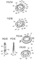
- the spring element has an annular basic shape in which segmented spring sections 321-324 of the annular receiving section 320 extend in the manner of tabs.
- the spring sections 321-324 extend radially to the insertion direction E (spring sections 321, 322) or axially to the insertion direction E (spring sections 323, 324).
- the spring element 32 is held within the housing 30, 31 of the balancing device 3 by the spring portions 321-324 in abutment with the circumferential housing walls of the housing 30, 31 are.
- the spring element 32 can also be positively fixed within the housing 30, 31 and thus rotatably held by the insertion direction E in the housing 30, 31.
- the spring element 32 is configured with annular spring portions 321-324 which surround the annular receiving portion 320 circumferentially and are closed in the circumferential direction to the insertion direction E.
- the spring portions 321-324 extend substantially radially to the insertion direction E (spring portions 321, 322) or axially to the insertion direction E (spring portions 323, 324).
- the spring element 32 according to the embodiment according to Figs. 6A-6D can be defined via recesses 326 in the spring portion 321 positively within the housing 30, 31 of the balancing device 3 and thus rotatably held in the housing 30, 31.
- the compensation device 3 is, as I said, to compensate for deviations from a desired position and a desired angle when attaching the connector part 1 to an associated mating connector part 4. How this is done in accordance with the sectional views Figs. 7A to 7E illustrated.
- the support member 33 In a starting position prior to attachment of the connector part 1 to the associated mating connector part 4, the support member 33 is with its pin member 332 in an approximately central position at the opening 311 of the housing part 31 of the balancer 3. About the spring element 32, the support member 33 and about the with the support member 33 firmly connected plug housing 2 in position to the housing 30, 31 of the balancing device 3 held such that longitudinal axes L. (corresponding to the rotational symmetry axes) of the support member 33 and the dome 300 are aligned.
- the insertion of the connector part 1 with its plug sections 21, 22 in the associated mating connector part 4 causes the position of the plug housing 2 of the position of (stationary) mating connector part 4 adapts. Because only when the plug housing 2 is aligned with its plug portions 21, 22 with the mating connector part 4, an insertion into the mating connector part 4 is possible.
- the position of the plug housing 2 changes relative to the housing 30, 31 of the compensating device 3, which is held in position on the holding device 5.
- the plug housing 2 can move laterally in a direction B transversely to the insertion direction E relative to the housing 30, 31 ( Fig. 7C ) or in directions C, D relative to the housing 30, 31 of the balancing device 3 ( Fig. 7D, 7E ).
- FIGS. 7C-7E How out Figs. 7C-7E can be seen in these changes in position of the support member 33 in the housing 30, 31, the longitudinal axes L1, L2 of the dome 300 on the one hand and the support member 33 on the other not (more) with each other.
- the carrier element 33 can pivot relative to the dome 300, as shown in FIG Fig. 7D, 7E is shown. Because the radius R2 of the spherical-cap-shaped bearing surface 331 of the carrier element 33 is greater than the radius R1 of the spherical cap-shaped contact surface 301 of the mandrel 300, this pivoting can take place with a simultaneous lateral change in position of the carrier element 33 relative to the mandrel 300.
- the lateral movement of the carrier element 33 within the housing 30, 31 is limited by the opening 311 penetrated by the pin element 332 of the carrier element 33 in the housing part 31 of the compensation device 3 Fig. 7C and 7D shown. At maximum deflection, the pin element 332 comes into contact with the border of the opening 311, so that the lateral adjustability of the carrier element 33 in the housing 30, 31 is limited.
- a rotation of the plug housing 2 can be compensated for the insertion direction E. This is done under rotational deformation of the spring element 32, on the one hand rotatably held in the housing 30, 31 and on the other hand rotatably connected to the support member 33 and is thus subjected to torsional load of the plug housing 2 to torsion.
- the change in position of the support member 33 relative to the housing 30, 31 is always under deformation of the spring member 32. Does not load (more) between the plug housing 2 and the balancing device 3, so relaxes the spring element 32 and sets the carrier element 33 in its initial position ( Fig. 7A ) within the housing 30, 31 back.
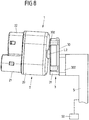
- Fig. 8 schematically shows a holding device 5, which is connected via the connecting element 302 with the housing 30, 31 of the balancing device 3 and serves to attach the connector part 1 semi-automatically or fully automatically to an associated mating connector part 4.
- the holding device 5 can be controlled, for example via a suitable control device 50, wherein the position of the mating connector part 4, for example, sensory, for example, using optical sensors can be detected to the connector part 1 automatically approach the mating connector part 4 and with the mating connector part 4 in engagement bring.
- one or more electrical lines can be led out of the housing 2, for example, by exiting the housing 2 laterally or upwards or downwards and being moved away from the housing 2, possibly around the compensating device 3. Several lines can also escape to different sides of the housing 2.
- the invention is not limited to use with charging plugs at charging stations or other charging devices, but can be used quite generally in connectors.
- the balancing device can be easily and inexpensively constructed and manufactured, allows a secure and reliable attachment of a connector part to a mating connector part and can provide a balance of positional deviations of a connector part when fitting to a mating connector part in an advantageous manner.
Landscapes
- Details Of Connecting Devices For Male And Female Coupling (AREA)
Description
- Die Erfindung betrifft ein Steckverbinderteil nach dem Oberbegriff des Anspruchs 1.
- Ein solches Steckverbinderteil umfasst ein Steckgehäuse, das zumindest einen Steckabschnitt aufweist, der in einer Einsteckrichtung steckend mit einem Gegensteckverbinderteil zum elektrischen Kontaktieren des Steckverbinderteils mit dem Gegensteckverbinderteil verbunden werden kann.
- Ein solches Steckverbinderteil kann beispielsweise als Ladestecker zum elektrischen Aufladen einer Batterie eines Elektrofahrzeugs ausgebildet sein. In diesem Fall kann das Steckverbinderteil beispielsweise über eine elektrische Zuleitung mit einer Ladestation verbunden und in eine Ladebuchse eines Elektrofahrzeugs einzustecken sein, so dass bei angeschlossenem Steckverbinderteil Ladeströme von der Ladestation hin zum Elektrofahrzeug übertragen werden können, um auf diese Weise die Batterie des Elektrofahrzeugs aufzuladen.
- Zum Aufladen von Elektrofahrzeugen kommen heutzutage vermehrt auch vollautomatische oder halbautomatische Ladeeinrichtungen zum Einsatz. Bei solchen Ladeeinrichtungen wird das Steckverbinderteil nicht manuell an ein zugeordnetes Gegensteckverbinderteil (auf Seiten des Elektrofahrzeugs) angesteckt, sondern das Steckverbinderteil wird unter Verwendung einer elektromechanischen Baugruppe automatisch dem Gegensteckverbinderteil angenähert und steckend mit dem Gegensteckverbinderteil in Eingriff gebracht.
- Solche vollautomatischen oder haltautomatischen Ladeeinrichtungen erfordern, dass die Position des Gegensteckverbinderteils am Fahrzeug mit hinreichender Genauigkeit z.B. unter Verwendung einer optischen Sensorik erfasst wird, damit das Steckverbinderteil in automatischer Weise dem Gegensteckverbinderteil angenähert und mit dem Gegensteckverbinderteil in Eingriff gebracht werden kann. Eine solche Positionserkennung ist jedoch nur mit begrenzter Genauigkeit möglich. Zudem ist eine Achserkennung zum achsparallelen Ansetzen des Steckverbinderteils an das zugeordnete Gegensteckverbinderteil schwierig. Kommt es bei einem Ansetzen eines Steckverbinderteils an ein zugeordnetes Gegensteckverbinderteil jedoch zu einem Abweichen der Achsen des Steckverbinderteils und des Gegensteckverbinderteils voneinander, so kann dies dazu führen, dass Kontakte des Steckverbinderteils und des Gegensteckverbinderteils unter einem lateralen Versatz oder auch unter einem Winkelversatz aneinander angesetzt werden, was zu einem Verkanten des Steckverbinderteils an dem Gegensteckverbinderteil und damit zu erheblichen Belastungen am Steckverbinderteil und am Gegensteckverbinderteil und insbesondere auch an deren elektrischen Kontakten führen kann.
- Solche Belastungen können auch auftreten, wenn es bei einem Ladevorgang zu einer Lageänderung des Fahrzeugs relativ zur Ladestation kommt, was mit einer Lageänderung des Steckverbinderteils relativ zum Gegensteckverbinderteil einhergehen kann. Solche Lageänderungen können beispielsweise bei einem Be- und Entladen des Fahrzeugs und einer damit verbundenen Absenkung oder Anhebung des Fahrzeugs auftreten.
- Es besteht somit ein Bedürfnis nach einem Steckverbinderteil, das in einem gewissen Maß Winkel- und Positionsabweichungen relativ zu einem Gegensteckverbinderteil zulässt, das gleichzeitig aber sicher und zuverlässig zur elektrischen Kontaktierung mit einem zugeordneten Gegensteckverbinderteil in Eingriff gebracht werden kann.
- Bei einem aus der
DE 10 2010 035 868 B3 bekannten Steckverbinderteil sind Steckkontakte schwimmend an einem Kontaktträger aufgenommen. Zudem ist der Kontaktträger schwimmend an einem Gehäuse angeordnet, so dass bei einem steckenden Verbinden mit einem Gegensteckverbinderteil Positions- und Winkelabweichungen ausgeglichen werden können. - Die Merkmale des Oberbegriffs des Anspruchs 1 sind aus der
GB 2 373 378 A GB 2 360 642 A - Aufgabe der vorliegenden Erfindung ist es, ein Steckverbinderteil zur Verfügung zu stellen, das auf einfache, kostengünstige Weise einen zuverlässigen Ausgleich von Positions- und/oder Winkelabweichungen gegenüber einer Soll-Position und einem Soll-Winkel beim Ansetzen an ein zugeordnetes Gegensteckverbinderteil ermöglicht.
- Diese Aufgabe wird durch einen Gegenstand mit den Merkmalen des Anspruchs 1 gelöst. Demnach weist das Steckverbinderteil eine an dem Steckgehäuse angeordnete Ausgleichseinrichtung auf, die ein Gehäuse, ein mit dem Steckgehäuse verbundenes, an dem Gehäuse angeordnetes Trägerelement und ein das Trägerelement gegenüber dem Gehäuse vorspannendes Federelement aufweist, wobei das Trägerelement unter elastischer Verformung des Federelements relativ zu dem Gehäuse bewegbar ist.
- Das Steckverbinderteil weist somit ein Steckgehäuse und eine an dem Steckgehäuse angeordnete Ausgleicheinrichtung auf. Das Steckgehäuse dient zum steckenden Verbinden mit einem zugeordneten Gegensteckverbinderteil und weist hierzu ein oder mehrere Steckabschnitte auf, an denen z.B. elektrische Kontakte zum elektrischen Kontaktieren mit zugeordneten Gegenkontakten auf Seiten des Gegensteckverbinderteils angeordnet sein können. Die Ausgleichseinrichtung dient demgegenüber dazu, Abweichungen in der Position und/oder dem Winkel, unter denen das Steckverbinderteil an das zugeordnete Gegensteckverbinderteil angesetzt wird, gegenüber einer Soll-Position und einem Soll-Winkel auszugleichen. Generell ist das Steckverbinderteil mit seinem Steckgehäuse in eine Einsteckrichtung an das Gegensteckverbinderteil anzusetzen, wobei dies (nur) in einer definierten (Soll-)Position unter einem definierten (Soll-)Winkel, nämlich fluchtend zum Gegensteckverbinderteil, möglich ist. Kommt es beim Ansetzen des Steckverbinderteils an das Gegensteckverbinderteil zu Abweichungen zu dieser Soll-Position und zu diesem Soll-Winkel, so können diese Abweichungen durch die Ausgleichseinrichtung ausgeglichen werden.
- Dies erfolgt unter elastischer Verformung des Federelements, über das das an dem Gehäuse angeordnete Trägerelement gegenüber dem Gehäuse vorgespannt ist. Mit dem Gehäuse kann beispielsweise eine geeignete Halteeinrichtung verbunden sein, über die das Steckverbinderteil auf elektromechanische Weise bewegt und dem Gegensteckverbinderteil angenähert werden kann. Mit dem Trägerelement ist demgegenüber das Steckgehäuse des Steckverbinderteils verbunden. Kommt es beim Ansetzen des Steckgehäuses an das Gegensteckverbinderteil zu Abweichungen von der Soll-Position oder dem Soll-Winkel, so kann sich das mit dem Steckgehäuse verbundene Trägerelement relativ zu dem Gehäuse bewegen, so dass solche Abweichungen ausgeglichen werden können und es zu keinem Verkanten des Steckgehäuses mit dem Gegensteckverbinderteil kommt und die Belastungen insbesondere an den elektrischen Kontakten des Steckverbinderteils und des Gegensteckverbinderteils reduziert sind.
- Das Trägerelement ist mit einem scheibenförmigen Basisabschnitt innerhalb eines Innenraums des Gehäuses der Ausgleichseinrichtung angeordnet und somit von dem Gehäuse eingefasst. Von dem Basisabschnitt kann sich in diesem Fall beispielsweise ein Zapfenelement in Richtung des Steckgehäuses erstrecken, wobei dieses Zapfenelement eine Öffnung des Gehäuses der Ausgleichseinrichtung durchgreift und an einem vom Basisabschnitt des Trägerelements abliegenden Ende mit dem Steckgehäuse verbunden ist. Über den Basisabschnitt ist das Trägerelement somit innerhalb des Gehäuses der Ausgleichseinrichtung gehalten und dabei über das Federelement gegenüber dem Gehäuse vorgespannt. Ändert sich die Lage des Steckgehäuses relativ zu dem Gehäuse der Ausgleichseinrichtung, so bewegt sich der Basisabschnitt der Trägerelements innerhalb des Gehäuses, was mit einer Verformung des Federelements innerhalb des Gehäuses einhergeht.
- Damit sich das Trägerelement mit seinem Basisabschnitt innerhalb des Gehäuses bewegen kann, ist die Öffnung des Gehäuses, die von dem Zapfenelement des Trägerelements durchgriffen wird, vorzugsweise größer als die lateralen Abmessungen des Zapfenelements, so dass sich das Zapfenelement quer zur Einsteckrichtung innerhalb der Öffnung bewegen kann.
- Das Trägerelement ist vorzugsweise drehfest an dem Federelement festgelegt. Das Trägerelement wird somit in definierter Position an dem Federelement gehalten und über das Federelement in dem Gehäuse positioniert. Aufgrund des das Trägerelement gegenüber dem Gehäuse vorspannenden Federelements wird das Trägerelement in einer im Wesentlichen nicht ausgelenkten Stellung relativ zu dem Gehäuse gehalten, wenn das Steckverbinderteil nicht mit einem zugeordneten Gegensteckverbinderteil in Eingriff steht.
- Das Gehäuse kann beispielsweise zweiteilig aus zwei aneinander anzusetzenden Gehäuseteilen gefertigt sein. An einem dieser Gehäuseteile ist beispielsweise ein in Richtung der Einsteckrichtung in den Innenraum des Gehäuses hinein vorspringender Dom ausgebildet, der dazu dient, beim Ansetzen des Steckverbinderteils an ein zugeordnetes Gegensteckverbinderteil auf das Trägerelement einzuwirken, um hinreichende Steckkräfte auf das Trägerelement und darüber auf das Steckgehäuse zum steckenden Verbinden mit dem Gegensteckverbinderteil zu übertragen.
- In einer nicht ausgelenkten Stellung ist hierbei der Dom vorteilhafterweise zu dem Trägerelement beabstandet und steht somit nicht mit dem Trägerelement in Anlage. Wird das Steckverbinderteil an ein zugeordnetes Gegensteckverbinderteil angesetzt, so wird das Federelement axial entlang der Einsteckrichtung komprimiert, was dazu führt, dass der Dom in Anlage mit einer Lagerfläche des Trägerelements gelangt und somit axiale Kräfte in das Trägerelement eingeleitet werden können. Eine Haltereinrichtung, die mit dem Gehäuse der Ausgleichseinrichtung verbunden ist und Steckkräfte in das Gehäuse der Ausgleichseinrichtung einleitet, kann somit bei Anlage des Doms an der Lagerfläche des Trägerelements axial auf das Trägerelement drücken und somit das Steckgehäuse, das mit dem Trägerelement verbunden ist, in Eingriff mit dem zugeordneten Gegensteckverbinderteil bringen.
- Der Dom weist in einer vorteilhaften Ausgestaltung eine Anlagefläche auf, die kugelkalottenförmig ausgebildet ist und mit der Lagerfläche des Trägerelements in Anlage zu bringen ist. Weist auch die Lagerfläche des Trägerelements eine Kugelkalottenform auf, so bilden der Dom und die Lagerfläche des Trägerelements zusammen ein Gleitlager, das ein Verschwenken des Trägerelements relativ zu dem Gehäuse unter gleitender Führung des am Trägerelement anliegenden Doms ermöglicht.
- Hierbei kann vorteilhaft sein, dass die Lagerfläche des Trägerelements und die Anlagefläche des Doms, die beide kugelkalottenförmig ausgebildet sind, unterschiedliche Radien aufweisen. Ist der Radius der kugelkalottenförmigen Anlagefläche des Doms kleiner als der Radius der kugelkalottenförmigen Lagerfläche des Trägerelements, können der Dom und das Trägerelement zueinander verschwenken und zudem auch lateral (quer zur Einsteckrichtung) zueinander versetzt werden, so dass in günstiger Weise Positions- und Winkelabweichungen unter Anlage des Doms des Gehäuses an der Lagerfläche des Trägerelements und somit unter axialer Kraftübertragung vom Gehäuse der Ausgleichsvorrichtung auf das Steckgehäuse ausgeglichen werden können.
- Das Federelement kann beispielsweise aus Kunststoff, beispielsweise einem hochelastischen Elastomer, hergestellt sein. Das Federelement kann beispielsweise eine ringförmige Grundform aufweisen und sich um die Einsteckrichtung herum in dem Innenraum des Gehäuses der Ausgleichseinrichtung erstrecken. Über das Federelement kann das Trägerelement insbesondere entgegen der Einsteckrichtung und quer zur Einsteckrichtung gegenüber dem Gehäuse vorgespannt sein, so dass das Trägerelement entgegen der Einsteckrichtung dem in Richtung der Einsteckrichtung von einem Boden des Gehäuses vorspringenden Dom axial angenähert und zudem lateral (quer zur Einsteckrichtung) in dem Gehäuse unter Deformation des Federelements versetzt werden kann.
- Das Trägerelement ist vorzugsweise formschlüssig an dem Federelement gehalten. Hierzu kann das Federelement beispielsweise einen Aufnahmeabschnitt aufweisen, der ringförmig ausgebildet ist und an den das Trägerelement beispielsweise mit seinem Basisabschnitt angesetzt werden kann. Von diesem Aufnahmeabschnitt können sich in diesem Fall beispielsweise eine Mehrzahl von Federabschnitten nach Art von Federlippen erstrecken, wobei diese Federabschnitte sich beispielsweise radial zur Einsteckrichtung und axial entlang der Einsteckrichtung von dem Aufnahmeabschnitt erstrecken und darüber eine elastische Verbindung des Trägerelements mit dem Gehäuse der Ausgleichseinrichtung herstellen.
- In einer ersten Ausführungsform können die Federabschnitte beispielsweise sich ringförmig um den Aufnahmeabschnitt herum erstrecken.
- Denkbar und möglich ist in seiner zweiten Ausführungsform aber auch, dass die Federabschnitte nach Art von Segmenten in Umfangsrichtung um die Einsteckrichtung unterbrochen sind und somit keine geschlossenen Ringe ausbilden.
- Der der Erfindung zugrunde liegende Gedanke soll nachfolgend anhand der in den Figuren dargestellten Ausführungsbeispiele näher erläutert werden. Es zeigen:
- Fig. 1A
- eine perspektivische Ansicht eines Steckverbinderteils;
- Fig. 1B
- eine andere perspektivische Ansicht des Steckverbinderteils, zusammen mit einem Gegensteckverbinderteil, mit dem das Steckverbinderteil in einer Einsteckrichtung in Eingriff zu bringen ist;
- Fig. 2A
- eine Ansicht des Steckverbinderteils von hinten;
- Fig. 2B
- eine Seitenansicht des Steckverbinderteils;
- Fig. 2C
- eine Ansicht des Steckverbinderteils von vorne;
- Fig. 3A
- eine perspektivische Explosionsansicht einer Ausgleichseinrichtung des Steckverbinderteils;
- Fig. 3B
- eine andere perspektivische Ansicht der Ausgleichseinrichtung;
- Fig. 4
- eine Schnittansicht durch die Ausgleichseinrichtung gemäß
Fig. 3A, 3B ; - Fig. 5A, 5B
- Ansichten eines ersten Ausführungsbeispiels eines Federelements der Ausgleichseinrichtung;
- Fig. 6A, 6B
- perspektivische Ansichten eines zweiten Ausführungsbeispiels eines Federelements;
- Fig. 6C
- eine Seitenansicht des Ausführungsbeispiels des Federelements gemäß
Fig. 6A, 6B ; - Fig. 6D
- eine Schnittansicht entlang der Linie I-I gemäß
Fig. 6A ; - Fig. 7A-7E
- Schnittansichten entlang der Linie II-II gemäß
Fig. 2A , in unterschiedlichen Lagen der Ausgleichseinrichtung relativ zu einem Steckgehäuse des Steckverbinderteils; und - Fig. 8
- eine Ansicht des Steckverbinderteils im Zusammenwirken mit einer Halteeinrichtung zum vollautomatischen oder halbautomatischen Ansetzen des Steckverbinderteils an ein zugeordnetes Gegensteckverbinderteil.
-
Fig. 1A, 1B zeigen ein Ausführungsbeispiel eines Steckverbinderteils 1, das, wie schematisch inFig. 1B dargestellt, mit einem zugeordneten Gegensteckverbinderteil 4 steckend in eine Einsteckrichtung E in Eingriff gebracht werden kann. Das Steckverbinderteil 1 kann beispielsweise Bestandteil einer Ladeeinrichtung und somit als Ladestecker ausgebildet sein, der mit einem zugeordneten Gegensteckverbinderteil 4 in Form einer Ladebuchse steckend in Eingriff gebracht werden kann, um Ladeströme beispielsweise zwischen einer Ladestation und einem Elektrofahrzeug zum Aufladen von Batterien des Elektrofahrzeugs zu übertragen. - Das Steckverbinderteil 1 umfasst ein Steckgehäuse 2 mit einem Gehäuseabschnitt 20, von dem Steckabschnitte 21, 22 in Einsteckrichtung E vorstehen. Die Steckabschnitt 21, 22 können in eine Einstecköffnung 40 des Gegensteckverbinderteils 4 in die Einsteckrichtung E eingesteckt werden, um auf diese Weise an den Steckabschnitten 21, 22 angeordnete elektrische Kontaktelemente 210, 220 mit zugeordneten Gegenkontaktelementen des Gegensteckverbinderteils 4 elektrisch zu kontaktieren.
- Rückwärtig der Steckabschnitte 21, 22 ist das Steckgehäuse 2 mit einer Ausgleichseinrichtung 3 verbunden, die dazu dient, Positionsabweichungen und Winkelabweichungen beim Ansetzen des Steckverbinderteils 1 an das Gegensteckverbinderteil 4 auszugleichen und auf diese Weise ein Verkanten des Steckverbinderteils 1 mit seinen Steckabschnitten 21, 22 in der Einstecköffnung 40 des Gegensteckverbinderteils 4 zu verhindern und Belastungen insbesondere an den Kontaktelementen 210, 220 zu reduzieren.
- An der Ausgleichseinrichtung 3 kann beispielsweise, wie dies schematisch in Fig. 9 dargestellt ist, eine elektromechanische Halteeinrichtung 5 angreifen, die über ein Verbindungselement 302 mit einem Gehäuse 30, 31 der Ausgleichseinrichtung 3 verbunden ist und dazu dient, das Steckverbinderteil 1 in automatischer, gesteuerter Weise an das Gegensteckverbinderteil 4 anzusetzen und mit diesem in Eingriff zu bringen.
-
Fig. 2A bis 2C zeigen eine Rückansicht (Fig. 2A ), eine Seitenansicht (Fig. 2B ) und eine Vorderansicht (Fig. 2C ) des Steckverbinderteils 1. Wie insbesondere ausFig. 2B ersichtlich, ist die Ausgleichseinrichtung 3 über ein Zapfenelement 332 eines Trägerelements (das nachstehend noch im Einzelnen beschrieben werden soll) mit dem Gehäuseabschnitt 20 des Steckgehäuses 2 verbunden, wobei die Lage des Zapfenelements 332 und darüber des Steckgehäuses 2 relativ zu dem Gehäuse 30, 31 der Ausgleichseinrichtung 3 veränderbar ist und auf diese Weise Abweichungen gegenüber einer Soll-Position und einem Soll-Winkel beim Ansetzen des Steckverbinderteils 1 an ein zugeordnetes Gegensteckverbinderteil 4 ausgeglichen werden können. -
Fig. 3A, 3B zeigen perspektivische Explosionsansichten der Ausgleichseinrichtung 3, währendFig. 4 eine Schnittansicht entlang der Linie II-II gemäßFig. 2A der Ausgleichseinrichtung 3 darstellt. Die Ausgleichseinrichtung 3 weist ein Gehäuse auf, das durch Gehäuseteile 30, 31 gebildet ist, die in zusammengesetztem Zustand einen Innenraum 310 einfassen. Ein erstes Gehäuseteil 30 trägt hierbei das Verbindungselement 302 zur Verbindung mit einer (externen) Halteeinrichtung 5, wie sie schematisch in Fig. 9 dargestellt ist. Ein zweites Gehäuseteil 31 ist dem Steckgehäuse 2 zugewandt und in montiertem Zustand fest mit dem ersten Gehäuseteil 30 verbunden. - In dem Innenraum 310 des Gehäuses 30, 31 ist ein Federelement 32 angeordnet, das mit einem Basisabschnitt 330 eines Trägerelements 33 verbunden ist und das Trägerelement 33 gegenüber dem Gehäuse 30, 31 vorspannt. Das Federelement 32 weist einen ringförmigen Aufnahmeabschnitt 320 auf, in den das Trägerelement 33 mit seinem Basisabschnitt 330 eingesetzt ist, wobei Formschlusselemente 334 in Form von Vorsprüngen an dem Basisabschnitt 330 des Trägerelements 33 in Formschlusselemente 325 in Form von Aussparungen an dem Aufnahmeabschnitt 320 des Federelements 32 eingreifen und auf diese Weise das Trägerelement 33 drehfest an dem Federelement 32 festlegen.
- Von dem Basisabschnitt 330 des Trägerelements 33 steht, an einer dem Federelement 32 abgewandten Seite, ein Zapfenelement 332 vor, das eine Öffnung 311 an dem zweiten Gehäuseteil 31 durchgreift und über einen Verbindungsabschnitt 333 fest mit dem Gehäuseabschnitt 20 des Steckgehäuses 2 verbunden ist.
- Innenseitig an dem ersten Gehäuseteil 30 ist ein Dom 300 ausgebildet, der in Richtung der Einsteckrichtung von dem Gehäuseteil 30 in Richtung des Trägerelements 33 vorsteht. Der Dom 300 weist an einer dem Trägerelement 33 zugewandten Seite eine Anlagefläche 301 mit einer Kugelkalottenform auf, die einer ebenfalls kugelkalottenförmigen Lagerfläche 331 an einer dem Dom 300 zugewandten Seite des Trägerelements 33 gegenübersteht und dazu ausgebildet ist, mit der Lagerfläche 331 bei Einstecken des Steckverbinderteils 1 in das Gegensteckverbinderteil 4 in Anlage zu gelangen.
- Wie aus der Schnittansicht gemäß
Fig. 4 ersichtlich, ist in einer nicht ausgelenkten Ausgangsstellung das Trägerelement 33 über das Federelement 32 in vorgespannter Weise in dem Innenraum 310 zwischen den Gehäuseteilen 30, 31 gehalten. In dieser Ausgangsstellung ist der Dom 300 mit seiner Anlagefläche 301 axial entlang der Einsteckrichtung E von der Lagerfläche 331 beanstandet, so dass der Dom 300 nicht mit dem Trägerelement 33 in Anlage ist. - Wie ebenfalls aus der Schnittansicht gemäß
Fig. 4 ersichtlich, weisen die kugelkalottenförmige Anlagefläche 301 des Doms 300 und die kugelkalottenförmige Lagerfläche 331 des Trägerelements 33 unterschiedliche Radien R1, R2 auf. Der Radius R1 der Anlagefläche 301 ist hierbei kleiner als der Radius R2 der Lagerfläche 331. Dies ermöglicht, wie nachfolgend noch beschrieben werden soll, ein Verschwenken des Trägerelements 33 relativ zum Dom 300 innerhalb des Gehäuses 30, 31 und zudem eine laterale Verschiebung quer zur Einsteckrichtung E. - Das Federelement 32 ist federelastisch ausgebildet und beispielsweise aus einem Kunststoff, insbesondere einem Elastomer, gefertigt. Unterschiedliche Ausführungen des Federelements 32 sind hierbei denkbar und möglich.
- In einem ersten Ausführungsbeispiel, dargestellt in
Fig. 5A, 5B , weist das Federelement eine ringförmige Grundform auf, bei der sich von dem ringförmigen Aufnahmeabschnitt 320 segmentierte Federabschnitte 321-324 nach Art von Laschen erstrecken. Die Federabschnitte 321-324 erstrecken sich hierbei radial zur Einsteckrichtung E (Federabschnitte 321, 322) oder axial zur Einsteckrichtung E (Federabschnitte 323, 324). Über die Federabschnitte 321-324 ist das Federelement 32 innerhalb des Gehäuses 30, 31 der Ausgleichseinrichtung 3 gehalten, indem die Federabschnitte 321-324 in Anlage mit den umfänglichen Gehäusewandungen des Gehäuses 30, 31 sind. - Über Aussparungen 326 in zwei der Federabschnitte 321 kann das Federelement 32 zudem formschlüssig innerhalb des Gehäuses 30, 31 festgelegt und somit drehfest um die Einsteckrichtung E in dem Gehäuse 30, 31 gehalten sein.
- In einem anderen, in
Fig. 6A-6D dargestellten Ausführungsbeispiel ist das Federelement 32 mit ringförmigen Federabschnitten 321-324 ausgestaltet, die den ringförmigen Aufnahmeabschnitt 320 umfänglich umgeben und in Umfangsrichtung um die Einsteckrichtung E geschlossen sind. Wiederum erstrecken sich die Federabschnitte 321-324 im Wesentlichen radial zur Einsteckrichtung E (Federabschnitte 321, 322) oder axial zur Einsteckerichtung E (Federabschnitte 323, 324). - Auch das Federelement 32 gemäß dem Ausführungsbeispiel gemäß
Fig. 6A-6D kann über Aussparungen 326 in dem Federabschnitt 321 formschlüssig innerhalb des Gehäuses 30, 31 der Ausgleichseinrichtung 3 festgelegt und somit drehfest in dem Gehäuse 30, 31 gehalten sein. - Die Ausgleichseinrichtung 3 dient, wie gesagt, dazu, Abweichungen von einer Soll-Position und einem Soll-Winkel beim Ansetzen des Steckverbinderteils 1 an ein zugeordnetes Gegensteckverbinderteil 4 auszugleichen. Wie dies erfolgt, ist in den Schnittansichten gemäß
Fig. 7A bis 7E veranschaulicht. - In einer Ausgangsstellung vor Ansetzen des Steckverbinderteils 1 an das zugeordnete Gegensteckverbinderteil 4 befindet sich das Trägerelement 33 mit seinem Zapfenelement 332 in einer in etwa mittigen Lage an der Öffnung 311 des Gehäuseteils 31 der Ausgleichseinrichtung 3. Über das Federelement 32 wird das Trägerelement 33 und darüber das mit dem Trägerelement 33 fest verbundene Steckgehäuse 2 in Position zu dem Gehäuse 30, 31 der Ausgleichseinrichtung 3 gehalten derart, dass Längsachsen L (entsprechend den Rotationssymmetrieachsen) des Trägerelements 33 und des Doms 300 fluchten.
- Wird das Steckverbinderteil 1, wie in
Fig. 7B dargestellt, beispielsweise unter automatischer Führung mittels einer Halteeinrichtung 5, wie diese inFig. 8 dargestellt ist, an ein Gegensteckverbinderteil 4 angesetzt, so wird das Federelement 32 in eine der Einsteckrichtung E entgegengesetzte Richtung A komprimiert, wenn sich das Steckverbinderteil 1 mit den am Steckgehäuse 2 angeordneten Steckabschnitten 21, 22 mit dem Gegensteckverbinderteil 4 findet und sich dabei Gegenkräfte aufbauen, die zur Komprimierung des Federelements 32 hinreichend sind. Bei dieser Komprimierung des Federelements 32 fluchten die Längsachsen L des Trägerelements 33 und des Doms 300 zunächst (noch) miteinander. - Wird das Steckverbinderteil 1 nicht in exakt korrekter Position und unter exakt korrektem Winkel an das Gegensteckverbinderteil 4 angesetzt, so führt das Einstecken des Steckverbinderteils 1 mit seinen Steckabschnitten 21, 22 in das zugeordnete Gegensteckverbinderteil 4 dazu, dass sich die Lage des Steckgehäuses 2 der Lage des (stationären) Gegensteckverbinderteils 4 anpasst. Denn nur wenn das Steckgehäuse 2 mit seinen Steckabschnitten 21, 22 mit dem Gegensteckverbinderteil 4 fluchtet, ist ein Einstecken in das Gegensteckverbinderteil 4 möglich.
- Weil die Lage des Steckgehäuses 2 sich somit beim Finden mit dem Gegensteckverbinderteil 4 ändert und dem Gegensteckverbinderteil 4 anpasst, ändert sich die Lage des Steckgehäuses 2 relativ zu dem Gehäuse 30, 31 der Ausgleichseinrichtung 3, die über die Halteeinrichtung 5 in Position gehalten wird. Hierdurch kann sich das Steckgehäuse 2 lateral in eine Richtung B quer zur Einsteckrichtung E relativ zu dem Gehäuse 30, 31 verschieben (
Fig. 7C ) oder in Richtungen C, D relativ zu dem Gehäuse 30, 31 der Ausgleichseinrichtung 3 verschwenken (Fig. 7D, 7E ). - Wie aus
Fig. 7C-7E ersichtlich, fluchten bei diesen Lageänderungen des Trägerelements 33 in dem Gehäuse 30, 31 die Längsachsen L1, L2 des Doms 300 einerseits und des Trägerelements 33 andererseits nicht (mehr) miteinander. - Weil beim Einstecken des Steckgehäuses 2 in das zugeordnete Gegensteckverbinderteil 4 es aufgrund Komprimierung des Federelements 32 zu einer Anlage des Doms 300 mit der Lagerfläche 31 des Trägerelements 33 kommt, können über das Gehäuse 30, 31 der Ausgleichseinrichtung 3, an dem die Lagereinrichtung 5 angreift, hinreichende Steckkräfte zum Einstecken des Steckgehäuses 2 in das Gegensteckverbinderteil 4 übertragen werden. Dies erfolgt über die Anlage der Anlagefläche 301 des Doms 300 mit der Lagerfläche 331 des Trägerelements 33.
- Weil die Anlagefläche 301 des Doms 300 einerseits und die Lagerfläche 331 des Trägerelements 33 andererseits jeweils kugelkalottenförmig ausgebildet sind, kann das Trägerelement 33 gegenüber dem Dom 300 verschwenken, wie dies in
Fig. 7D, 7E dargestellt ist. Weil der Radius R2 der kugelkalottenförmigen Lagerfläche 331 des Trägerelements 33 größer ist als der Radius R1 der kugelkalottenförmigen Anlagefläche 301 des Doms 300, kann dieses Verschwenken bei gleichzeitiger lateraler Lageänderung des Trägerelements 33 relativ zu dem Dom 300 erfolgen. - Die laterale Bewegung des Trägerelements 33 innerhalb des Gehäuses 30, 31 ist begrenzt durch die von dem Zapfenelement 332 des Trägerelements 33 durchgriffene Öffnung 311 in dem Gehäuseteil 31 der Ausgleichseinrichtung 3. Dies ist beispielhaft in
Fig. 7C und7D dargestellt. Bei maximaler Auslenkung gelangt das Zapfenelement 332 mit der Umrandung der Öffnung 311 in Anlage, so dass die laterale Verstellbarkeit des Trägerelements 33 in dem Gehäuse 30, 31 begrenzt ist. - Soll das Steckgehäuse 2 entgegen der Einsteckrichtung E wiederum außer Eingriff mit dem Gegensteckverbinderteil 4 gezogen werden, so können Zugkräfte in das Gehäuse 30, 31 eingeleitet werden. Hierdurch gelangt das Trägerelement 33 in Anlage mit dem Gehäuseteil 31 und wird gegen dieses Gehäuseteil 31 gedrückt, so dass darüber die Zugkräfte in das Trägerelement 33 eingeleitet und auf das Steckgehäuse 2 übertragen werden. Das Steckverbinderteil 1 kann somit zuverlässig aus dem Gegensteckverbinderteil 4 entnommen werden.
- Grundsätzlich kann auch eine Rotation des Steckgehäuses 2 um die Einsteckrichtung E ausgeglichen werden. Dies erfolgt unter rotatorischer Deformation des Federelements 32, das einerseits drehfest in dem Gehäuse 30, 31 gehalten und andererseits drehfest mit dem Trägerelement 33 verbunden ist und bei rotatorischer Belastung des Steckgehäuses 2 somit auf Torsion belastet wird.
- Die Lageänderung des Trägerelements 33 relativ zu dem Gehäuse 30, 31 erfolgt stets unter Deformation des Federelements 32. Wirkt keine Last (mehr) zwischen dem Steckgehäuse 2 und der Ausgleichseinrichtung 3, so entspannt sich das Federelement 32 und stellt das Trägerelement 33 in seine Ausgangsstellung (
Fig. 7A ) innerhalb des Gehäuses 30, 31 zurück. -
Fig. 8 zeigt schematisch eine Halteeinrichtung 5, die über das Verbindungselement 302 mit dem Gehäuse 30, 31 der Ausgleichseinrichtung 3 verbunden ist und dazu dient, das Steckverbinderteil 1 halbautomatisch oder vollautomatisch an ein zugeordnetes Gegensteckverbinderteil 4 anzusetzen. Die Halteeinrichtung 5 kann beispielsweise über eine geeignete Steuereinrichtung 50 gesteuert werden, wobei die Position des Gegensteckverbinderteils 4 beispielsweise sensorisch, beispielsweise unter Verwendung von optischen Sensoren, erfasst werden kann, um das Steckverbinderteil 1 automatisch dem Gegensteckverbinderteil 4 anzunähern und mit dem Gegensteckverbinderteil 4 in Eingriff zu bringen. - Bei den vorangehend geschilderten Ausführungsbeispielen können ein oder mehrere elektrische Leitungen beispielsweise aus dem Gehäuse 2 herausgeführt werden, indem sie seitlich oder nach oben oder unten hin aus dem Gehäuse 2 austreten und von dem Gehäuse 2 weg, gegebenenfalls um die Ausgleichseinrichtung 3 herum verlegt werden. Mehrere Leitungen können auch zu unterschiedlichen Seiten aus dem Gehäuse 2 austreten.
- Der der Erfindung zugrunde liegende Gedanke ist nicht auf die vorangehend geschilderten Ausführungsbeispiele beschränkt, sondern lässt sich grundsätzlich auch in gänzlich anders gearteter Weise verwirklichen.
- So ist die Erfindung insbesondere nicht auf die Verwendung bei Ladesteckern an Ladestationen oder anderen Ladeeinrichtungen beschränkt, sondern lässt sich ganz allgemein bei Steckverbindern verwenden.
- Mit der beschriebenen Ausgleichseinrichtung wird ein Lageausgleich beim Ansetzen eines Steckverbinderteils an ein zugeordnetes Gegensteckverbinderteil unter Verwendung nur weniger Bauteile möglich. Die Ausgleichseinrichtung kann einfach und kostengünstig aufgebaut und hergestellt werden, ermöglicht ein sicheres und zuverlässiges Ansetzen eines Steckverbinderteils an ein Gegensteckverbinderteil und kann in vorteilhafter Weise einen Ausgleich von Lageabweichungen eines Steckverbinderteils beim Ansetzen an ein Gegensteckverbinderteil schaffen.
-
- 1
- Steckverbinderteil
- 2
- Steckgehäuse
- 20
- Gehäuseabschnitt
- 21, 22
- Steckabschnitt
- 210,220
- Kontaktelemente
- 3
- Ausgleichseinrichtung
- 30
- Gehäuseteil
- 300
- Dom
- 301
- Anlagefläche
- 302
- Verbindungselement
- 31
- Gehäuseteil
- 310
- Innenraum
- 311
- Öffnung
- 32
- Elastisches Element
- 320
- Aufnahmeabschnitt
- 321-324
- Federabschnitt
- 325
- Formschlusselement
- 326
- Aussparung
- 33
- Trägerelement
- 330
- Basisabschnitt
- 331
- Lagerfläche
- 332
- Zapfenelement
- 333
- Verbindungsabschnitt
- 334
- Formschlusselement
- 4
- Gegensteckverbinderteil
- 40
- Einstecköffnung
- 5
- Halteeinrichtung
- 50
- Steuereinrichtung
- A-D
- Richtung
- E
- Einsteckrichtung
- L, L1, L2
- Längsachse
- R1, R2
- Radius
Claims (13)
- Steckverbinderteil (1), mit
einem Steckgehäuse (20), das zumindest einen Steckabschnitt (20, 21) aufweist, der in eine Einsteckrichtung (E) steckend mit einem Gegensteckverbinderteil (4) zum elektrischen Kontaktieren des Steckverbinderteils (1) mit dem Gegensteckverbinderteil (4) verbindbar ist, und eine an dem Steckgehäuse (2) angeordnete Ausgleichseinrichtung (3), die ein Gehäuse (30, 31), ein mit dem Steckgehäuse (20) verbundenes, an dem Gehäuse (30, 31) angeordnetes Trägerelement (33) und ein das Trägerelement (33) gegenüber dem Gehäuse (30, 31) vorspannendes Federelement (32) aufweist, wobei das Trägerelement (33) unter elastischer Verformung des Federelements (32) relativ zu dem Gehäuse (30, 31) bewegbar ist, wobei das Trägerelement (33) mit einem Basisabschnitt (330) in einem Innenraum (310) des Gehäuses (30, 31) eingefasst ist, dadurch gekennzeichnet, dass das Trägerelement (33) ein an dem Basisabschnitt (330) angeordnetes Zapfenelement (332) aufweist und mit dem Zapfenelement (332) eine Öffnung (311) des Gehäuses (30, 31) durchgreift, wobei das Zapfenelement (332) quer zur Einsteckrichtung (E) in der Öffnung (311) bewegbar ist. - Steckverbinderteil (1) nach Anspruch 1, dadurch gekennzeichnet, dass das Trägerelement (33) drehfest an dem Federelement (33) festgelegt ist.
- Steckverbinderteil (1) nach Anspruch 1 oder 2, dadurch gekennzeichnet, dass das Gehäuse (30, 31) an einem Gehäuseteil (30) einen in Richtung der Einsteckrichtung (E) vorspringenden Dom (300) aufweist, der unter elastischer Verformung des Federelements (32) mit einer Lagerfläche (331) des Trägerelements (33) zur Kraftübertragung von dem Gehäuse (30, 31) auf das Trägerelement (33) in Einsteckrichtung (E) in Anlage bringbar ist.
- Steckverbinderteil (1) nach Anspruch 3, dadurch gekennzeichnet, dass der Dom (300) eine kugelkalottenförmige Anlagefläche (301) aufweist.
- Steckverbinderteil (1) nach Anspruch 3 oder 4, dadurch gekennzeichnet, dass die Lagerfläche (331) des Trägerelements (33) kugelkalottenförmig ist.
- Steckverbinderteil (1) nach Anspruch 5, dadurch gekennzeichnet, dass die kugelkalottenförmige Anlagefläche (301) des Doms (300) einen kleineren Radius (R1) aufweist als die kugelkalottenförmige Lagerfläche (331) des Trägerelements (33).
- Steckverbinderteil (1) nach einem der vorangehenden Ansprüche, dadurch gekennzeichnet, dass das Federelement (32) aus einem Elastomer gefertigt ist.
- Steckverbinderteil (1) nach einem der vorangehenden Ansprüche, dadurch gekennzeichnet, dass das Federelement (32) das Trägerelement (33) entgegen der Einsteckrichtung (E) und quer zur Einsteckrichtung (E) gegenüber dem Gehäuse (30, 31) vorspannt.
- Steckverbinderteil (1) nach einem der vorangehenden Ansprüche, dadurch gekennzeichnet, dass das Federelement (33) einen Aufnahmeabschnitt (320) zum formschlüssigen Aufnehmen des Trägerelements (33) aufweist.
- Steckverbinderteil (1) nach Anspruch 9, dadurch gekennzeichnet, dass das Federelement (32) eine Mehrzahl von axial entlang der Einsteckrichtung (E) und/oder radial zur Einsteckrichtung (E) von dem Aufnahmeabschnitt (320) vorstehenden Federabschnitten (321-324) aufweist.
- Steckverbinderteil (1) nach Anspruch 10, dadurch gekennzeichnet, dass die Federabschnitte (321-324) sich ringförmig um die Einsteckrichtung (E) erstrecken.
- Steckverbinderteil (1) nach Anspruch 10, dadurch gekennzeichnet, dass die Federabschnitte (321-324) in Umfangsrichtung um die Einsteckrichtung (E) unterbrochen sind.
- Steckverbinderteil (1) nach einem der vorangehenden Ansprüche, dadurch gekennzeichnet, dass das Gehäuse (30, 31) der Ausgleichseinrichtung (3) mit einer Halteeinrichtung (5) zur automatischen Positionierung des Steckverbinderteils (1) verbindbar ist.
Applications Claiming Priority (2)
| Application Number | Priority Date | Filing Date | Title |
|---|---|---|---|
| DE102015100452.6A DE102015100452A1 (de) | 2015-01-14 | 2015-01-14 | Steckverbinderteil mit einer Ausgleichseinrichtung |
| PCT/EP2016/050434 WO2016113238A1 (de) | 2015-01-14 | 2016-01-12 | Steckverbinderteil mit einer ausgleichseinrichtung |
Publications (2)
| Publication Number | Publication Date |
|---|---|
| EP3245692A1 EP3245692A1 (de) | 2017-11-22 |
| EP3245692B1 true EP3245692B1 (de) | 2019-01-02 |
Family
ID=55083427
Family Applications (1)
| Application Number | Title | Priority Date | Filing Date |
|---|---|---|---|
| EP16700312.8A Active EP3245692B1 (de) | 2015-01-14 | 2016-01-12 | Steckverbinderteil mit einer ausgleichseinrichtung |
Country Status (5)
| Country | Link |
|---|---|
| US (1) | US10439328B2 (de) |
| EP (1) | EP3245692B1 (de) |
| CN (1) | CN107112693B (de) |
| DE (1) | DE102015100452A1 (de) |
| WO (1) | WO2016113238A1 (de) |
Families Citing this family (8)
| Publication number | Priority date | Publication date | Assignee | Title |
|---|---|---|---|---|
| USD838906S1 (en) * | 2017-07-22 | 2019-01-22 | Helen Of Troy Limited | Adapter for a hair styling iron barrel |
| DE102019106747A1 (de) * | 2018-03-16 | 2019-09-19 | Hirschmann Automotive Gmbh | Steckverbindung insbesondere für ein Elektrofahrrad |
| LU101309B1 (de) * | 2019-07-11 | 2021-01-11 | Phoenix Contact E Mobility Gmbh | Elektrische Baugruppe mit einer Temperaturüberwachungseinrichtung |
| CN111211442B (zh) * | 2020-03-09 | 2025-11-11 | 上海电气集团股份有限公司 | 柔性充电连接装置及充电设备 |
| US12496918B2 (en) * | 2022-06-09 | 2025-12-16 | Japan Aviation Electronics Industry, Limited | Charging connector |
| EP4542785A1 (de) * | 2023-10-18 | 2025-04-23 | Siemens Industry Software NV | Elektrische mehrpolige steckverbinderanordnung, modulare bausteinanordnung |
| USD1087030S1 (en) * | 2023-11-30 | 2025-08-05 | Dongguan LanXin Charging Technology Co., Ltd. | Adapter |
| CN118336443B (zh) * | 2024-05-13 | 2024-10-29 | 山东龙立电子有限公司 | 一种双压力补偿调节结构及水下插拔连接器 |
Family Cites Families (15)
| Publication number | Priority date | Publication date | Assignee | Title |
|---|---|---|---|---|
| US3609637A (en) * | 1969-12-01 | 1971-09-28 | Clyde C Cole | Electrical connector |
| US4030797A (en) * | 1975-06-11 | 1977-06-21 | International Telephone And Telegraph Corporation | Electrical connector |
| US4815986A (en) * | 1987-08-14 | 1989-03-28 | Lucas Weinschel, Inc. | Self-aligning blind mate connector |
| US5147221A (en) * | 1989-08-13 | 1992-09-15 | The Starling Manufacturing Company | Combination socket and wingless cable-end radio pin connector |
| FR2685825B1 (fr) * | 1991-12-26 | 1994-04-01 | Ecia | Connecteur automatique autocentrable. |
| FR2756428B1 (fr) * | 1996-11-27 | 1999-02-12 | Gobin Daude | Connecteur electrique pour vehicule automobile |
| FR2806540B1 (fr) * | 2000-03-20 | 2002-10-04 | Fci Jupiter | Fiche telemanipulable |
| FR2818450B1 (fr) * | 2000-12-20 | 2004-12-10 | Fci France | Fiche telemanipulable |
| US6390841B1 (en) * | 2001-04-25 | 2002-05-21 | Lear Corporation | Self-aligning electrical connector |
| NL1025379C2 (nl) * | 2004-02-02 | 2005-08-03 | Framatome Connectors Int | Optisch connectorsysteem. |
| ATE529927T1 (de) * | 2009-06-24 | 2011-11-15 | Coninvers Gmbh | Elektrischer push-pull-steckverbinder |
| DE102010035868B3 (de) | 2010-08-30 | 2012-02-16 | Phoenix Contact Gmbh & Co. Kg | Elektrische Komponente |
| CN103367979B (zh) * | 2012-04-05 | 2016-02-17 | 株式会社起家来人 | 连接器组件 |
| DE102012111408B3 (de) * | 2012-11-26 | 2013-10-24 | HARTING Electronics GmbH | Verriegelungsmechanismus für Steckverbinder |
| DE202014011301U1 (de) * | 2014-09-02 | 2019-02-15 | Phoenix Contact Gmbh & Co. Kg | Gehäuse zum Verbinden mit einem Steckverbinderteil |
-
2015
- 2015-01-14 DE DE102015100452.6A patent/DE102015100452A1/de not_active Ceased
-
2016
- 2016-01-12 US US15/542,943 patent/US10439328B2/en active Active
- 2016-01-12 CN CN201680005724.2A patent/CN107112693B/zh not_active Expired - Fee Related
- 2016-01-12 EP EP16700312.8A patent/EP3245692B1/de active Active
- 2016-01-12 WO PCT/EP2016/050434 patent/WO2016113238A1/de not_active Ceased
Non-Patent Citations (1)
| Title |
|---|
| None * |
Also Published As
| Publication number | Publication date |
|---|---|
| EP3245692A1 (de) | 2017-11-22 |
| CN107112693B (zh) | 2019-08-13 |
| DE102015100452A1 (de) | 2016-07-14 |
| CN107112693A (zh) | 2017-08-29 |
| US10439328B2 (en) | 2019-10-08 |
| US20180269631A1 (en) | 2018-09-20 |
| WO2016113238A1 (de) | 2016-07-21 |
Similar Documents
| Publication | Publication Date | Title |
|---|---|---|
| WO2016113238A1 (de) | Steckverbinderteil mit einer ausgleichseinrichtung | |
| EP2045882B1 (de) | Selbstjustierender Gerätesteckverbinder | |
| WO2013060772A1 (de) | Zweiteiliger elektrischer steckverbinder | |
| DE60304801T2 (de) | Kurzschlusssteckverbindung für eine Zündpille | |
| DE102014014536A1 (de) | Anschlussblock | |
| DE102019129436A1 (de) | Vorrichtung zum konduktiven Laden mit einem verbesserten Zentriermittel | |
| WO2018228853A1 (de) | Steckverbinderteil mit verstemmten kontaktelementen und verfahren zu dessen herstellung | |
| WO2016079077A1 (de) | Federkraftklemme | |
| EP4091218B1 (de) | Verbindungsteil für ein steckverbindungssystem | |
| DE102019216266A1 (de) | Elektrisch betriebenes Fahrzeug mit einer wechselbaren Traktionsbatterie | |
| WO2019076620A1 (de) | Steckverbinderteil mit einem verriegelungselement | |
| DE102017213941B4 (de) | Steckverbinder mit Kurzschlussklemme | |
| DE102017123704A1 (de) | Steckverbinderteil mit einem Verbindungselement zum Verbinden von Gehäuseteilen | |
| EP1336229A1 (de) | Ladegerät | |
| DE102014216518A1 (de) | Elektronische Steuereinheit sowie Moldwerkzeug und Verfahren zum Herstellen einer elektronischen Steuereinheit | |
| DE29512614U1 (de) | Anschlußklemme | |
| DE102017129429A1 (de) | Schneckengetriebe | |
| DE102015106084A1 (de) | Vorrichtung zur automatisierten Montage eines Schalenelements an einem Pleuelelement | |
| DE4236794C2 (de) | Elektrische Steckverbindung | |
| EP4066328B1 (de) | Steckerbaugruppe, stecker für eine solche steckerbaugruppe sowie verfahren zur montage der steckerbaugruppe | |
| LU504123B1 (de) | Steckverbinderteil für ein Ladesystem zum Aufladen eines Elektrofahrzeugs | |
| DE102018201648A1 (de) | Energiebereitstellungseinrichtung für ein Kraftfahrzeug, Verfahren zum Betreiben einer Energiebereitstellungseinrichtung, Kontaktiervorrichtung für ein Kraftfahrzeug sowie elektrisches Energiebereitstellungssystem für ein Kraftfahrzeug | |
| EP2385206A2 (de) | Schaltanordnung | |
| EP1930990B1 (de) | Elektrische Steckverbindung | |
| DE102018107886A1 (de) | Steckverbindersystem mit einem bistabilen Element |
Legal Events
| Date | Code | Title | Description |
|---|---|---|---|
| STAA | Information on the status of an ep patent application or granted ep patent |
Free format text: STATUS: THE INTERNATIONAL PUBLICATION HAS BEEN MADE |
|
| PUAI | Public reference made under article 153(3) epc to a published international application that has entered the european phase |
Free format text: ORIGINAL CODE: 0009012 |
|
| STAA | Information on the status of an ep patent application or granted ep patent |
Free format text: STATUS: REQUEST FOR EXAMINATION WAS MADE |
|
| 17P | Request for examination filed |
Effective date: 20170712 |
|
| AK | Designated contracting states |
Kind code of ref document: A1 Designated state(s): AL AT BE BG CH CY CZ DE DK EE ES FI FR GB GR HR HU IE IS IT LI LT LU LV MC MK MT NL NO PL PT RO RS SE SI SK SM TR |
|
| AX | Request for extension of the european patent |
Extension state: BA ME |
|
| DAV | Request for validation of the european patent (deleted) | ||
| DAX | Request for extension of the european patent (deleted) | ||
| GRAP | Despatch of communication of intention to grant a patent |
Free format text: ORIGINAL CODE: EPIDOSNIGR1 |
|
| STAA | Information on the status of an ep patent application or granted ep patent |
Free format text: STATUS: GRANT OF PATENT IS INTENDED |
|
| INTG | Intention to grant announced |
Effective date: 20180727 |
|
| RIC1 | Information provided on ipc code assigned before grant |
Ipc: H01R 13/631 20060101ALI20180713BHEP Ipc: H01R 13/64 20060101ALI20180713BHEP Ipc: H01R 13/71 20060101AFI20180713BHEP |
|
| RIN1 | Information on inventor provided before grant (corrected) |
Inventor name: FUEHRER, THOMAS Inventor name: BABEZKI, ROBERT |
|
| GRAS | Grant fee paid |
Free format text: ORIGINAL CODE: EPIDOSNIGR3 |
|
| GRAA | (expected) grant |
Free format text: ORIGINAL CODE: 0009210 |
|
| STAA | Information on the status of an ep patent application or granted ep patent |
Free format text: STATUS: THE PATENT HAS BEEN GRANTED |
|
| AK | Designated contracting states |
Kind code of ref document: B1 Designated state(s): AL AT BE BG CH CY CZ DE DK EE ES FI FR GB GR HR HU IE IS IT LI LT LU LV MC MK MT NL NO PL PT RO RS SE SI SK SM TR |
|
| REG | Reference to a national code |
Ref country code: GB Ref legal event code: FG4D Free format text: NOT ENGLISH |
|
| REG | Reference to a national code |
Ref country code: CH Ref legal event code: EP Ref country code: AT Ref legal event code: REF Ref document number: 1085609 Country of ref document: AT Kind code of ref document: T Effective date: 20190115 |
|
| REG | Reference to a national code |
Ref country code: IE Ref legal event code: FG4D Free format text: LANGUAGE OF EP DOCUMENT: GERMAN |
|
| REG | Reference to a national code |
Ref country code: DE Ref legal event code: R096 Ref document number: 502016003068 Country of ref document: DE |
|
| REG | Reference to a national code |
Ref country code: NL Ref legal event code: MP Effective date: 20190102 |
|
| REG | Reference to a national code |
Ref country code: LT Ref legal event code: MG4D |
|
| PG25 | Lapsed in a contracting state [announced via postgrant information from national office to epo] |
Ref country code: NL Free format text: LAPSE BECAUSE OF FAILURE TO SUBMIT A TRANSLATION OF THE DESCRIPTION OR TO PAY THE FEE WITHIN THE PRESCRIBED TIME-LIMIT Effective date: 20190102 |
|
| PG25 | Lapsed in a contracting state [announced via postgrant information from national office to epo] |
Ref country code: SE Free format text: LAPSE BECAUSE OF FAILURE TO SUBMIT A TRANSLATION OF THE DESCRIPTION OR TO PAY THE FEE WITHIN THE PRESCRIBED TIME-LIMIT Effective date: 20190102 Ref country code: LT Free format text: LAPSE BECAUSE OF FAILURE TO SUBMIT A TRANSLATION OF THE DESCRIPTION OR TO PAY THE FEE WITHIN THE PRESCRIBED TIME-LIMIT Effective date: 20190102 Ref country code: FI Free format text: LAPSE BECAUSE OF FAILURE TO SUBMIT A TRANSLATION OF THE DESCRIPTION OR TO PAY THE FEE WITHIN THE PRESCRIBED TIME-LIMIT Effective date: 20190102 Ref country code: PT Free format text: LAPSE BECAUSE OF FAILURE TO SUBMIT A TRANSLATION OF THE DESCRIPTION OR TO PAY THE FEE WITHIN THE PRESCRIBED TIME-LIMIT Effective date: 20190502 Ref country code: ES Free format text: LAPSE BECAUSE OF FAILURE TO SUBMIT A TRANSLATION OF THE DESCRIPTION OR TO PAY THE FEE WITHIN THE PRESCRIBED TIME-LIMIT Effective date: 20190102 Ref country code: NO Free format text: LAPSE BECAUSE OF FAILURE TO SUBMIT A TRANSLATION OF THE DESCRIPTION OR TO PAY THE FEE WITHIN THE PRESCRIBED TIME-LIMIT Effective date: 20190402 Ref country code: PL Free format text: LAPSE BECAUSE OF FAILURE TO SUBMIT A TRANSLATION OF THE DESCRIPTION OR TO PAY THE FEE WITHIN THE PRESCRIBED TIME-LIMIT Effective date: 20190102 |
|
| PG25 | Lapsed in a contracting state [announced via postgrant information from national office to epo] |
Ref country code: IS Free format text: LAPSE BECAUSE OF FAILURE TO SUBMIT A TRANSLATION OF THE DESCRIPTION OR TO PAY THE FEE WITHIN THE PRESCRIBED TIME-LIMIT Effective date: 20190502 Ref country code: LV Free format text: LAPSE BECAUSE OF FAILURE TO SUBMIT A TRANSLATION OF THE DESCRIPTION OR TO PAY THE FEE WITHIN THE PRESCRIBED TIME-LIMIT Effective date: 20190102 Ref country code: GR Free format text: LAPSE BECAUSE OF FAILURE TO SUBMIT A TRANSLATION OF THE DESCRIPTION OR TO PAY THE FEE WITHIN THE PRESCRIBED TIME-LIMIT Effective date: 20190403 Ref country code: HR Free format text: LAPSE BECAUSE OF FAILURE TO SUBMIT A TRANSLATION OF THE DESCRIPTION OR TO PAY THE FEE WITHIN THE PRESCRIBED TIME-LIMIT Effective date: 20190102 Ref country code: RS Free format text: LAPSE BECAUSE OF FAILURE TO SUBMIT A TRANSLATION OF THE DESCRIPTION OR TO PAY THE FEE WITHIN THE PRESCRIBED TIME-LIMIT Effective date: 20190102 Ref country code: BG Free format text: LAPSE BECAUSE OF FAILURE TO SUBMIT A TRANSLATION OF THE DESCRIPTION OR TO PAY THE FEE WITHIN THE PRESCRIBED TIME-LIMIT Effective date: 20190402 |
|
| REG | Reference to a national code |
Ref country code: CH Ref legal event code: PL |
|
| PG25 | Lapsed in a contracting state [announced via postgrant information from national office to epo] |
Ref country code: LU Free format text: LAPSE BECAUSE OF NON-PAYMENT OF DUE FEES Effective date: 20190112 |
|
| REG | Reference to a national code |
Ref country code: DE Ref legal event code: R097 Ref document number: 502016003068 Country of ref document: DE |
|
| REG | Reference to a national code |
Ref country code: BE Ref legal event code: MM Effective date: 20190131 |
|
| REG | Reference to a national code |
Ref country code: IE Ref legal event code: MM4A |
|
| PG25 | Lapsed in a contracting state [announced via postgrant information from national office to epo] |
Ref country code: AL Free format text: LAPSE BECAUSE OF FAILURE TO SUBMIT A TRANSLATION OF THE DESCRIPTION OR TO PAY THE FEE WITHIN THE PRESCRIBED TIME-LIMIT Effective date: 20190102 Ref country code: MC Free format text: LAPSE BECAUSE OF FAILURE TO SUBMIT A TRANSLATION OF THE DESCRIPTION OR TO PAY THE FEE WITHIN THE PRESCRIBED TIME-LIMIT Effective date: 20190102 Ref country code: RO Free format text: LAPSE BECAUSE OF FAILURE TO SUBMIT A TRANSLATION OF THE DESCRIPTION OR TO PAY THE FEE WITHIN THE PRESCRIBED TIME-LIMIT Effective date: 20190102 Ref country code: CZ Free format text: LAPSE BECAUSE OF FAILURE TO SUBMIT A TRANSLATION OF THE DESCRIPTION OR TO PAY THE FEE WITHIN THE PRESCRIBED TIME-LIMIT Effective date: 20190102 Ref country code: EE Free format text: LAPSE BECAUSE OF FAILURE TO SUBMIT A TRANSLATION OF THE DESCRIPTION OR TO PAY THE FEE WITHIN THE PRESCRIBED TIME-LIMIT Effective date: 20190102 Ref country code: IT Free format text: LAPSE BECAUSE OF FAILURE TO SUBMIT A TRANSLATION OF THE DESCRIPTION OR TO PAY THE FEE WITHIN THE PRESCRIBED TIME-LIMIT Effective date: 20190102 Ref country code: SK Free format text: LAPSE BECAUSE OF FAILURE TO SUBMIT A TRANSLATION OF THE DESCRIPTION OR TO PAY THE FEE WITHIN THE PRESCRIBED TIME-LIMIT Effective date: 20190102 Ref country code: DK Free format text: LAPSE BECAUSE OF FAILURE TO SUBMIT A TRANSLATION OF THE DESCRIPTION OR TO PAY THE FEE WITHIN THE PRESCRIBED TIME-LIMIT Effective date: 20190102 |
|
| PLBE | No opposition filed within time limit |
Free format text: ORIGINAL CODE: 0009261 |
|
| STAA | Information on the status of an ep patent application or granted ep patent |
Free format text: STATUS: NO OPPOSITION FILED WITHIN TIME LIMIT |
|
| PG25 | Lapsed in a contracting state [announced via postgrant information from national office to epo] |
Ref country code: BE Free format text: LAPSE BECAUSE OF NON-PAYMENT OF DUE FEES Effective date: 20190131 Ref country code: SM Free format text: LAPSE BECAUSE OF FAILURE TO SUBMIT A TRANSLATION OF THE DESCRIPTION OR TO PAY THE FEE WITHIN THE PRESCRIBED TIME-LIMIT Effective date: 20190102 |
|
| 26N | No opposition filed |
Effective date: 20191003 |
|
| PG25 | Lapsed in a contracting state [announced via postgrant information from national office to epo] |
Ref country code: LI Free format text: LAPSE BECAUSE OF NON-PAYMENT OF DUE FEES Effective date: 20190131 Ref country code: CH Free format text: LAPSE BECAUSE OF NON-PAYMENT OF DUE FEES Effective date: 20190131 |
|
| PG25 | Lapsed in a contracting state [announced via postgrant information from national office to epo] |
Ref country code: IE Free format text: LAPSE BECAUSE OF NON-PAYMENT OF DUE FEES Effective date: 20190112 |
|
| PG25 | Lapsed in a contracting state [announced via postgrant information from national office to epo] |
Ref country code: FR Free format text: LAPSE BECAUSE OF NON-PAYMENT OF DUE FEES Effective date: 20190302 Ref country code: SI Free format text: LAPSE BECAUSE OF FAILURE TO SUBMIT A TRANSLATION OF THE DESCRIPTION OR TO PAY THE FEE WITHIN THE PRESCRIBED TIME-LIMIT Effective date: 20190102 |
|
| PG25 | Lapsed in a contracting state [announced via postgrant information from national office to epo] |
Ref country code: TR Free format text: LAPSE BECAUSE OF FAILURE TO SUBMIT A TRANSLATION OF THE DESCRIPTION OR TO PAY THE FEE WITHIN THE PRESCRIBED TIME-LIMIT Effective date: 20190102 |
|
| PG25 | Lapsed in a contracting state [announced via postgrant information from national office to epo] |
Ref country code: MT Free format text: LAPSE BECAUSE OF FAILURE TO SUBMIT A TRANSLATION OF THE DESCRIPTION OR TO PAY THE FEE WITHIN THE PRESCRIBED TIME-LIMIT Effective date: 20190102 |
|
| GBPC | Gb: european patent ceased through non-payment of renewal fee |
Effective date: 20200112 |
|
| PG25 | Lapsed in a contracting state [announced via postgrant information from national office to epo] |
Ref country code: GB Free format text: LAPSE BECAUSE OF NON-PAYMENT OF DUE FEES Effective date: 20200112 |
|
| PG25 | Lapsed in a contracting state [announced via postgrant information from national office to epo] |
Ref country code: CY Free format text: LAPSE BECAUSE OF FAILURE TO SUBMIT A TRANSLATION OF THE DESCRIPTION OR TO PAY THE FEE WITHIN THE PRESCRIBED TIME-LIMIT Effective date: 20190102 |
|
| PG25 | Lapsed in a contracting state [announced via postgrant information from national office to epo] |
Ref country code: HU Free format text: LAPSE BECAUSE OF FAILURE TO SUBMIT A TRANSLATION OF THE DESCRIPTION OR TO PAY THE FEE WITHIN THE PRESCRIBED TIME-LIMIT; INVALID AB INITIO Effective date: 20160112 |
|
| REG | Reference to a national code |
Ref country code: AT Ref legal event code: MM01 Ref document number: 1085609 Country of ref document: AT Kind code of ref document: T Effective date: 20210112 |
|
| PG25 | Lapsed in a contracting state [announced via postgrant information from national office to epo] |
Ref country code: AT Free format text: LAPSE BECAUSE OF NON-PAYMENT OF DUE FEES Effective date: 20210112 |
|
| PG25 | Lapsed in a contracting state [announced via postgrant information from national office to epo] |
Ref country code: MK Free format text: LAPSE BECAUSE OF FAILURE TO SUBMIT A TRANSLATION OF THE DESCRIPTION OR TO PAY THE FEE WITHIN THE PRESCRIBED TIME-LIMIT Effective date: 20190102 |
|
| P01 | Opt-out of the competence of the unified patent court (upc) registered |
Effective date: 20230525 |
|
| P02 | Opt-out of the competence of the unified patent court (upc) changed |
Effective date: 20230530 |
|
| PGFP | Annual fee paid to national office [announced via postgrant information from national office to epo] |
Ref country code: DE Payment date: 20260320 Year of fee payment: 11 |