EP3244714A1 - Gehäuse und stelleinrichtung mit gehäuse - Google Patents
Gehäuse und stelleinrichtung mit gehäuse Download PDFInfo
- Publication number
- EP3244714A1 EP3244714A1 EP17170094.1A EP17170094A EP3244714A1 EP 3244714 A1 EP3244714 A1 EP 3244714A1 EP 17170094 A EP17170094 A EP 17170094A EP 3244714 A1 EP3244714 A1 EP 3244714A1
- Authority
- EP
- European Patent Office
- Prior art keywords
- housing
- labyrinth
- edge region
- interior
- region
- Prior art date
- Legal status (The legal status is an assumption and is not a legal conclusion. Google has not performed a legal analysis and makes no representation as to the accuracy of the status listed.)
- Granted
Links
Images


Classifications
-
- H—ELECTRICITY
- H05—ELECTRIC TECHNIQUES NOT OTHERWISE PROVIDED FOR
- H05K—PRINTED CIRCUITS; CASINGS OR CONSTRUCTIONAL DETAILS OF ELECTRIC APPARATUS; MANUFACTURE OF ASSEMBLAGES OF ELECTRICAL COMPONENTS
- H05K5/00—Casings, cabinets or drawers for electric apparatus
- H05K5/02—Details
- H05K5/0213—Venting apertures; Constructional details thereof
- H05K5/0214—Venting apertures; Constructional details thereof with means preventing penetration of rain water or dust
-
- Y—GENERAL TAGGING OF NEW TECHNOLOGICAL DEVELOPMENTS; GENERAL TAGGING OF CROSS-SECTIONAL TECHNOLOGIES SPANNING OVER SEVERAL SECTIONS OF THE IPC; TECHNICAL SUBJECTS COVERED BY FORMER USPC CROSS-REFERENCE ART COLLECTIONS [XRACs] AND DIGESTS
- Y02—TECHNOLOGIES OR APPLICATIONS FOR MITIGATION OR ADAPTATION AGAINST CLIMATE CHANGE
- Y02T—CLIMATE CHANGE MITIGATION TECHNOLOGIES RELATED TO TRANSPORTATION
- Y02T10/00—Road transport of goods or passengers
- Y02T10/10—Internal combustion engine [ICE] based vehicles
- Y02T10/12—Improving ICE efficiencies
Definitions
- the present invention relates to a housing of an electrical and / or electronic component, in particular a control device and / or an adjusting device for the mechanical actuation of a component of a machine, preferably an internal combustion engine. Furthermore, the invention relates to a control device or actuating device equipped with such a housing. The invention also relates to a machine equipped with such an adjusting device.
- an exhaust gas turbocharger which may have, for example, a variable turbine geometry or a wastegate valve as an actuatable component. Accordingly, such an exhaust gas turbocharger can be equipped with an adjusting device in order to actuate the variable turbine geometry or the wastegate valve as needed.
- a pump may represent such a machine, which has as an actuatable component a valve for adjusting a volume flow. With the help of the adjusting device can then operate the valve.
- exhaust gas recirculation as an engine having an exhaust gas recirculation valve as the actuatable component for setting an exhaust gas recirculation rate.
- This machine can also be equipped with an actuating device for actuating the exhaust gas recirculation valve.
- Actuators which are suitable for the mechanical actuation of a component of a machine, basically comprise a housing which can be constructed in several parts, but at least in two parts, and accordingly has a first housing part and a second housing part.
- the housing contains at least one interior, in which an electric motor is arranged.
- This electric motor is drivingly coupled to an actuator of the actuating device, which is arranged on the outside of the housing.
- the actuator in turn is provided and adapted to be coupled to the respective component to be actuated by means of the actuator.
- the two housing parts which represent separate components, are fastened to one another and lie against one another in a contact area. This contact area is closed in a circumferential direction of the housing along the inner space.
- control devices with electrical and / or electronic elements.
- it may be a control device for actuating an actuating device of the type described above.
- the housing of the control device can be at least partially integrated into the housing of the adjusting device.
- this or the housing may be exposed to temperatures that vary in a relatively wide temperature range. This applies in particular to applications in the field of an internal combustion engine.
- In the interior of the housing is due to manufacturing a certain volume of air, which would contract or expand depending on the temperature. In a hermetically sealed housing this would lead to corresponding pressure changes in the interior. Varying pressures in the interior, however, burden the structure of the housing. It is therefore desirable to equalize the pressure between the interior of the housing and an environment of the housing. For such a pressure equalization, it is basically possible to provide a pressure equalization opening on the housing, for example on the first housing part or on the second housing part.
- such a pressure compensation opening has the disadvantage that through the pressure equalization opening there is a risk that impurities, such as dirt particles and moisture, get into the interior, which can lead to damage of the electric motor and / or further arranged in the interior components of the control device.
- impurities such as dirt particles and moisture
- membranes are relatively expensive, both in production and in the application.
- the present invention is concerned with the problem of providing for an actuator of the type described above or for a machine equipped therewith an improved embodiment, which is characterized by an inexpensive Realization of the pressure balance between the interior and the environment is characterized.
- the invention is based on the general idea to form a pressure compensation labyrinth in the contact area, which allows pressure equalization between the interior and the environment.
- the pressure compensation labyrinth is fluidly connected on the one hand to the interior and on the other hand to the environment, so that the pressure balance labyrinth fluidly connects the interior with the environment.
- Such a pressure-compensating labyrinth is relatively easy for gases to pass through, while it is relatively impermeable to solid or liquid contaminants.
- a pressure compensation for the interior can be relatively easily realized, while on the other hand, the risk of contamination of the interior is reduced.
- a pressure compensation labyrinth is that it can be taken into account particularly simply in the production of the housing parts, so that in particular additional installation costs are eliminated.
- An inexpensive manufacturability is realized in particular by the fact that the pressure compensation labyrinth is formed in the contact area, in which the two housing parts abut each other. This makes it possible in particular to form the pressure compensation labyrinth partially in the one housing part and partially in the other housing part or to design such that it is completed only when assembling the two housing parts. In other words, the pressure equalization labyrinth is parted like the housing in the contact area. In particular, by the separation or division of the pressure compensation labyrinth in the contact region, injection molding of the housing parts can thus be realized. the respective components of the pressure compensation labyrinth are integrally formed in the respective housing part. This results in the production of the housing parts by the integration of the pressure compensation labyrinth no significant additional costs.
- the pressure-compensating labyrinth extends in the circumferential direction only along a part of the contact region, for example over less than 180 °, preferably over less than 90 °.
- the pressure compensation labyrinth has a labyrinth channel extending in the circumferential direction of the housing along a portion of the contact area, the labyrinth channel is fluidly connected via an interior opening with the interior, while fluidly via an environmental opening with the environment connected is. Furthermore, the interior opening and the environmental opening are offset from each other in the circumferential direction.
- This design has the consequence that air flows at an overpressure in the interior through the pressure compensation labyrinth to the environment or flows at a negative pressure in the interior of the environment through the pressure compensation labyrinth to the interior, at the transition between the interior opening and labyrinth channel and at the transition between ambient opening and Labyrinth channel is deflected respectively, which does not affect the gas flow or not significantly, while entrained impurities are deposited due to the higher inertial forces.
- the first housing part in the contact region has a first edge region which contains at least part of the labyrinth channel, while the second housing part has a second edge region in the contact region, which rests axially on the first edge region.
- the labyrinth channel is exclusively in the first Edge area formed.
- the second edge region is then preferably designed just opposite the labyrinth channel.
- the labyrinth channel is formed partly in the first edge region and partly in the second edge region.
- the labyrinth channel in the contact region transverse to the circumferential direction having a channel cross-section which is bounded radially inwardly and radially outwardly from the first edge region.
- the channel cross-section is delimited at a side facing away from the second edge region axially from the first edge region and bounded at a second edge region axially facing side from the second edge region.
- labyrinth channel in the absence of the second housing part of the trained in the first edge region labyrinth channel is axially open on one side.
- the axially open side of the labyrinth channel is then closed by the second edge region.
- the axial direction of the housing is defined by the mounting direction in which the two housing parts are fastened together. It extends regularly perpendicular to a plane, so-called parting plane in which the housing parts abut each other.
- the axial direction extends parallel to the mounting direction.
- the circumferential direction of the actuator or the housing refers to the axial direction and runs around them.
- the axial direction of the actuator is defined by the axis of rotation of the electric motor and extends parallel thereto.
- the rotation axis and the mounting direction are parallel to each other.
- the circumferential direction of the actuator or the housing refers to the axial direction and runs around them.
- the first edge region in the region of the pressure-compensating labyrinth can have a double-walled design, so that it has an inner wall facing the inner space there and an outer wall facing away from the inner space. Between inner wall and outer wall of the labyrinth channel is formed. In addition, the inner wall limits the channel cross section radially inwardly, while the outer wall limits the channel cross section radially outward. Due to the double-walled design of the first edge region along the pressure equalization labyrinth, the production is particularly inexpensive.
- the first edge region in the region of the pressure compensation labyrinth can have a radially projecting web which delimits the channel cross section at an axially opposite side from the second edge region and from which the outer wall protrudes when it protrudes radially outward, or the inner wall extends when it protrudes radially inwards.
- This measure also leads to a compact and therefore inexpensive solution.
- Another embodiment provides to form the interior opening in the inner wall.
- the interior opening is expedient radially oriented.
- the orientation of an opening in the present context means the direction of a longitudinal central axis of the respective opening, along which the opening can be mainly flowed through.
- the interior opening is radially oriented and is axially spaced from the web. Furthermore, the interior opening can be produced particularly easily if it is axially open on one side in the absence of the second housing part. This axial spacing leads to a jump in the cross-section, which increases the separation efficiency for contaminants.
- an inner collar is formed at least in the region of the pressure compensation labyrinth at the second edge region, which is arranged radially spaced from the inner wall in the interior, which projects axially from the remaining second edge region and which axially overlaps the interior opening.
- the environmental opening may be formed in the outer wall.
- the ambient opening can be oriented radially.
- the environmental opening can be realized particularly easily.
- the environmental opening can be made so that it is axially open on one side in the absence of the second housing part.
- the surrounding opening may be radially oriented and spaced axially from the web. This also realizes a cross-sectional jump at the transition between the environmental opening and the labyrinth channel, which improves the separation effect.
- Another embodiment provides that at the second edge region, at least in the region of the pressure compensation labyrinth, an outer collar is formed, which is arranged radially spaced from the outer wall in the environment and axially protrudes from the remaining second edge region and axially overlaps the surrounding opening.
- an outer collar is formed, which is arranged radially spaced from the outer wall in the environment and axially protrudes from the remaining second edge region and axially overlaps the surrounding opening.
- the surrounding opening is formed in the web.
- the environmental opening is then oriented axially.
- the environmental opening may be formed in the second edge region. Again, the environmental opening may be preferably oriented axially.
- the positioning of the environmental opening and / or its orientation or orientation can be selected in particular depending on the respective installation situation of the adjusting device.
- the environmental opening is arranged or oriented so that it leads in the installed state of the adjusting device from the labyrinth channel down, so essentially in the direction of gravity to the environment. In this way, impurities that can settle in the labyrinth channel, escape again from the pressure balance labyrinth in the environment.
- the interior opening can be arranged in the region of a first circumferential end of the labyrinth channel, while the surrounding opening is arranged in the region of a second circumferential end of the labyrinth channel.
- a filter element is arranged in the pressure-compensating labyrinth.
- a filter element may be formed, for example, by a typical filter material, for example a non-woven, which is permeable to gas and impermeable to the interfering contaminants is.
- the arrangement of the filter element in the pressure balance labyrinth advantageously takes place in such a way that a pressure equalization path formed in the pressure compensation labyrinth and communicating with the environment fluidically passes through the pressure compensation path through the filter element. In this way, any gas flow that forms to equalize pressure between the interior and the environment through the pressure balance labyrinth along the pressure equalization path, forced to flow completely through the filter element.
- a gas-permeable membrane is arranged in the pressure-compensating labyrinth.
- this membrane which may for example consist of PTFE (polytetrafluoroethylene), is arranged in the pressure balance labyrinth so that any gas that is to be replaced for pressure equalization between the environment and the interior, must penetrate the membrane. It is also conceivable to design the filter element as a gas-permeable membrane.
- the one housing part forms a pot and contains a substantial proportion of the interior, while the other housing part forms a cover to close the pot.
- the first housing part is designed as a pot, while the second housing part is designed as a lid.
- both housing parts are made of plastic.
- the housing parts can be glued or welded together or be firmly connected to each other by plasticizing one of the housing parts. While welding both connection partners during welding, it is sufficient for plasticizing to melt only one of the connection partners. The melt then acts on the one hand like an adhesive and on the other hand can also produce fusion bonds with the other connection partner.
- the contact area extends in a plane which can be referred to as a dividing plane or parting plane of the housing.
- a control device has at least one electrical and / or electronic element and is equipped with a housing of the type described above.
- the respective electrical and / or electronic element is arranged in the interior of the housing.
- the control device can serve, for example, for driving an electric motor, preferably a brushless DC motor, that is to say a BLDC motor, where BLDC stands for "brushless direct current ".
- the control device comprises a plurality of electrical and / or electronic elements.
- Typical electronic and / or electrical elements of the control device are or form power electronics and / or sensors, for example for the current rotational position determination of the electric motor or an actuator driven therewith.
- An adjusting device serves for the mechanical actuation of a component of a machine, preferably an internal combustion engine, and comprises an electric motor for driving an actuator, which serves for coupling with the component to be actuated, and a control device of the type described above, which serves to drive the electric motor.
- the electric motor as the respective electrical and / or electronic element of the control device is arranged in the interior of the housing.
- the actuator may expediently be arranged on the outside of the housing.
- Another adjusting device also serves for the mechanical actuation of a component of a machine, preferably an internal combustion engine, and is itself equipped with a housing of the type described above. Further, the adjusting device comprises an electric motor arranged in the interior of the housing, which is for driving an outside of the housing arranged actuator is used, which in turn is provided for coupling with the component to be actuated.
- a machine according to the invention which is equipped with an adjusting device of the type described above, can be formed for example by an exhaust gas turbocharger or by an exhaust gas recirculation system.
- the component of the respective machine to be actuated with the aid of the adjusting device can be formed by a variable turbine geometry or by a wastegate valve in a machine designed as an exhaust-gas turbocharger.
- the component to be actuated by means of the adjusting device may be an exhaust gas recirculation valve for setting an exhaust gas recirculation rate.
- FIG. 1 comprises an adjusting device 1, which is suitable and intended for the mechanical actuation of a component, not shown here, of a machine, likewise not shown here, a housing 2 which has a first housing part 3 and a second housing part 4.
- a housing 2 which has a first housing part 3 and a second housing part 4.
- an electric motor 6 is arranged in the housing 2.
- This electric motor 6 is drivingly coupled to an actuator 7, which is located outside the housing 2.
- a transmission 8 may be arranged, which drives a drive shaft of the electric motor 6 with a led out of the housing 2 shaft 9 connects to which the actuator 7 is rotatably mounted.
- the actuator 7 also carries a pin 10 which is designed so that it can be coupled with that component which is to be mechanically actuated by means of the adjusting device 1.
- Fig. 1 is the first housing part 3 pot-shaped and contains an essential part, ie more than 50%, in the example more than 75% of the volume of the interior 5.
- the second housing part 4 is designed here as a lid, in the assembled state by the first housing part 3 closes formed pot.
- the interior 5 is completely enclosed by the two housing parts 3, 4.
- the two housing parts 3, 4 are configured here in one piece. It is also conceivable to design at least one of the housing parts 3, 4 in several parts.
- the two housing parts 3, 4 are separate components which are fastened to one another in the assembled state of the housing 2 and which abut one another in a contact area 11.
- This contact region 11 runs closed in a circumferential direction 12 of the housing 2 along the inner space 5.
- the circumferential direction 12 refers to a rotation axis 13 of the electric motor 6.
- This rotation axis 13 also defines an axial direction 14, which runs parallel to the rotation axis 13.
- the contact region 11 extends substantially in a plane which can also be referred to as a parting plane.
- the axial direction 14 is perpendicular to this dividing plane.
- the two housing parts 3, 4 expediently axially attached to each other, so that a mounting direction of the housing 2 is parallel to the axial direction 14.
- a control device 36 is indicated, which is also housed in the interior 5 of the housing 2.
- This control device 36 is used to drive the electric motor 6 and has a plurality of electrical and / or electronic elements 37, which may form, for example, a sensor and / or power electronics.
- a pressure compensation labyrinth 15 is formed, which connects the interior 5 fluidly with an environment 16 of the housing 2. The following is based on the Fig. 2 to 9 closer to this pressure compensation labyrinth 15 received.
- the labyrinth channel 17 extends in the circumferential direction 12 along part of the contact area 11. In the example shown, the labyrinth channel extends over less than 20% of the contact area 11.
- the interior opening 18 fluidly communicates with the interior 5.
- the environmental opening 19 is in fluid communication with the environment 16.
- the labyrinth channel 17 fluidly connects the interior opening 18 with the surrounding opening 19, so that ultimately the labyrinth channel 17 is fluidically connected to the interior 5 via the interior opening 18 and to the environment 16 via the environment opening 19. It is also noteworthy that the interior opening 18 and the surrounding opening 19 are arranged offset in the circumferential direction 12 to each other.
- the first housing part 3 has a first edge region 20, in which the labyrinth channel 17 is formed.
- the second housing part 4 has a second edge region 21 in the contact region 11.
- the second edge region 21 abuts axially on the first edge region 20.
- the first edge region 20 apparently penetrates axially into the second edge region 21. This merely serves to indicate a connection by welding or plasticizing between the first edge region 20 and the second edge region 21, in which preferably at least one axial end face of the first edge region 20 is heated.
- the labyrinth channel 17 is formed exclusively or completely in the first edge region 20 and only closed by the preferably flat second edge region 21.
- the labyrinth channel 17 is partially formed in the first edge region 20 and partially in the second edge region 21.
- the two sections of the labyrinth channel 17 are then open on each side facing each side. In this case, only when assembling the housing parts 3, 4 of the labyrinth channel 17 is completed while at the same time also closed laterally.
- Fig. 3 and 9 has the labyrinth channel 17 in the contact area 11 transverse to the circumferential direction 12, in the sectional views of 3 to 5 and 9 perpendicular to the plane of the drawing, a channel cross-section 22 which is bounded radially inwardly and radially outwardly from the first edge region 20. Furthermore, this channel cross-section 22 faces away axially from the second edge region 21, likewise delimited by the first edge region 20. On the other hand, facing the second edge region 21, the channel cross-section 22 is delimited by the second edge region 21. In the absence of the second housing part 4, the channel cross section 22 or the labyrinth channel 17 is thus axially open on one side. When attached second housing part 4, this axially open side of the labyrinth channel 17 is axially closed by the second edge region 21.
- the first edge region 20 is configured double-walled at least in the area of the pressure equalization labyrinth 15, wherein it has an inner wall 23 facing the inner space 5 and an outer wall 24 remote from the inner space 5. Furthermore, the inner wall 23 and the outer wall 24 form the radial boundary of the channel cross-section 22 at the first edge region 20. In the preferred example shown here, the first edge region 20 is configured double-walled exclusively in the area of the pressure-compensating labyrinth 15.
- the web 25 projects radially outward. Accordingly, in the example, the outer wall 24 starts from this web 25.
- the web 25 connects the inner wall 23 with the outer wall 24th
- the interior opening 18 is formed in the inner wall 23 and also radially oriented. Furthermore, at least Fig. 5 infer that the interior opening 18 is axially spaced from the web 25. Accordingly, there is a step 26 in the labyrinth channel 17 at the transition to the interior opening 18.
- an inner collar 27 can be formed on the second edge region 21, at least in the region of the pressure compensation labyrinth 15, an inner collar 27.
- the inner collar 27 is radially spaced from the inner wall 23 in the inner space 5 and overlaps the inner space opening 18 axially.
- the axial overlap of the interior opening 18 through the inner wall 27 is in Fig. 5 recognizable.
- the ambient opening 19 is formed in the outer wall 24 and expedient radially oriented.
- the environmental opening 19 may be expediently arranged so that it is axially spaced from the web 25.
- the second edge region 21 has an outer collar 29 at least in the area of the pressure compensation labyrinth 15.
- the outer collar 29 projects axially in the environment 16 and is radially from the outer wall 24 spaced. Further, the outer collar 29 overlaps the environmental opening 19 axially. This axial overlap is in Fig. 4 recognizable.
- Fig. 6 shows another embodiment in which the environmental opening 19 is formed in the web 25 and is axially oriented.
- the axial direction is oriented perpendicular to the plane of the drawing.
- the Fig. 7 and 8th show a further alternative embodiment in which the environmental opening 19 is formed in the second edge region 21 and also expediently axially oriented.
- the inner collar 27 and the outer collar 28 are not shown or not present. This is in Fig. 8 a connection zone 34 indicated, in which the connection of the two edge regions 20, 21 takes place together by means of gluing, welding or plasticizing.
- the Fig. 2 to 5 show an example in which the interior opening 18 is arranged in the region of a first peripheral end 30 of the labyrinth channel 17, while the surrounding opening 19 is arranged in the region of a second circumferential end 31 of the labyrinth channel 17.
- the entire length of the labyrinth channel 17 is used, which extends in the circumferential direction 12.
- the labyrinth channel 17 has a substantially constant channel cross-section 22 between the interior opening 18 and the surrounding opening 19 along its extension in the circumferential direction 12.
- the labyrinth channel 17 has a radially oriented bulge 32 between its two circumferential ends 30, 31.
- the channel cross-section 22 is radially enlarged.
- the bulge 32 is oriented radially outward in the examples shown here.
- the environmental opening 19 is positioned in the region of this bulge 32 and is axially oriented.
- Fig. 6 is the ambient opening 19 in the region of the bulge 12 and within the bulge 12 at the first edge region 20, namely in the web 25, is formed.
- the ambient opening 19 is formed in the region of the bulge 32 or in the bulge 32 on the second edge region 21.
- Fig. 9 shows purely by way of example an example of a particular embodiment in which a filter element 33 is arranged in the pressure-compensating labyrinth 15.
- the filter element 33 fills the entire channel cross-section 22, so that an unspecified pressure equalization path, which is formed in the pressure balance labyrinth 15 and the fluidically connects the interior 5 with the environment 16, through this filter element 33 leads.
- the filter element 33 can be designed as a gas-permeable membrane 35 according to an advantageous embodiment be. Likewise, it is conceivable to provide a separate gas-permeable membrane 35 additionally or alternatively to the filter element 33.
Landscapes
- Engineering & Computer Science (AREA)
- Microelectronics & Electronic Packaging (AREA)
- Control Of Throttle Valves Provided In The Intake System Or In The Exhaust System (AREA)
- Supercharger (AREA)
- Sealing Using Fluids, Sealing Without Contact, And Removal Of Oil (AREA)
Abstract
Description
- Die vorliegende Erfindung betrifft ein Gehäuse einer elektrischen und/oder elektronischen Komponente, insbesondere einer Steuereinrichtung und/oder einer Stelleinrichtung zum mechanischen Betätigen einer Komponente einer Maschine, vorzugsweise einer Brennkraftmaschine. Ferner betrifft die Erfindung eine mit einem solchen Gehäuse ausgestattete Steuereinrichtung bzw. Stelleinrichtung. Die Erfindung betrifft außerdem eine mit einer solchen Stelleinrichtung ausgestattete Maschine.
- Bei einer Vielzahl von Maschinen gibt es Komponenten, die mechanisch betätigt werden müssen, damit die jeweilige Komponente die ihr zugeordnete Funktion innerhalb der jeweiligen Maschine erfüllen kann. Von bevorzugtem Interesse ist als Maschine hierbei ein Abgasturbolader, der als betätigbare Komponente beispielsweise eine variable Turbinengeometrie oder ein Wastegateventil aufweisen kann. Dementsprechend kann ein derartiger Abgasturbolader mit einer Stelleinrichtung ausgestattet sein, um die variable Turbinengeometrie bzw. das Wastegateventil bedarfsabhängig zu betätigen. Selbstverständlich lassen sich auch andere Maschinen mit derartigen Stelleinrichtungen ausstatten. Beispielsweise kann eine Pumpe eine solche Maschine repräsentieren, die als betätigbare Komponente ein Ventil zum Einstellen eines Volumenstroms aufweist. Mit Hilfe der Stelleinrichtung lässt sich dann das Ventil betätigen. Ebenso ist denkbar, eine Abgasrückführung als Maschine aufzufassen, die als betätigbare Komponente ein Abgasrückführventil zum Einstellen einer Abgasrückführrate aufweist. Auch diese Maschine kann mit einer Stelleinrichtung zum Betätigen des Abgasrückführventils ausgestattet sein.
- Stelleinrichtungen, die sich zum mechanischen Betätigen einer Komponente einer Maschine eignen, umfassen grundsätzlich ein Gehäuse, das mehrteilig, zumindest jedoch zweiteilig, aufgebaut sein kann und dementsprechend ein erstes Gehäuseteil und ein zweites Gehäuseteil aufweist. Das Gehäuse enthält zumindest einen Innenraum, in dem ein Elektromotor angeordnet ist. Dieser Elektromotor ist mit einem Stellglied der Stelleinrichtung antriebsmäßig gekoppelt, das außen am Gehäuse angeordnet ist. Das Stellglied seinerseits ist dazu vorgesehen und adaptiert, mit der jeweiligen Komponente gekoppelt zu werden, die mit Hilfe der Stelleinrichtung betätigt werden soll. Im zusammengebauten Zustand der Stelleinrichtung sind die beiden Gehäuseteile, die separate Bauteile repräsentieren, aneinander befestigt und liegen dabei in einem Kontaktbereich aneinander an. Dieser Kontaktbereich läuft in einer Umfangsrichtung des Gehäuses entlang des Innenraums geschlossen um.
- Auch andere elektrische und/oder elektronische Komponenten besitzen ein Gehäuse, in dem elektrische und/oder elektronische Bauteile und/oder Baugruppen zum Schutz vor Umwelteinflüssen untergebracht sind. Von besonderem Interesse sind dabei Steuereinrichtungen mit elektrischen und/oder elektronischen Elementen. Beispielsweise kann es sich um eine Steuereinrichtung zum Ansteuern einer Stelleinrichtung der vorstehend beschriebenen Art handeln. Das Gehäuse der Steuereinrichtung kann dabei zumindest teilweise in das Gehäuse der Stelleinrichtung integriert sein.
- Je nach Einsatzort der Stelleinrichtung bzw. der Steuereirichtung kann diese bzw. das Gehäuse Temperaturen ausgesetzt sein, die in einem relativ großen Temperaturbereich variieren. Dies gilt insbesondere für Anwendungen im Bereich einer Brennkraftmaschine. Im Innenraum des Gehäuses befindet sich herstellungsbedingt ein gewisses Luftvolumen, das sich abhängig von der Temperatur zusammenziehen oder ausdehnen möchte. Bei einem hermetisch verschlossenen Gehäuse würde dies zu entsprechenden Druckänderungen im Innenraum führen. Variierende Drücke im Innenraum belasten jedoch die Struktur des Gehäuses. Es ist daher ein Druckausgleich zwischen dem Innenraum des Gehäuses und einer Umgebung des Gehäuses erwünscht. Für einen derartigen Druckausgleich ist es grundsätzlich möglich, am Gehäuse eine Druckausgleichsöffnung vorzusehen, beispielsweise am ersten Gehäuseteil oder am zweiten Gehäuseteil. Eine derartige Druckausgleichsöffnung hat jedoch den Nachteil, dass durch die Druckausgleichsöffnung die Gefahr besteht, dass Verunreinigungen, wie zum Beispiel Schmutzpartikel und Feuchtigkeit, in den Innenraum gelangen, was zu einer Beschädigung des Elektromotors und/oder weiterer im Innenraum angeordneter Bauteile der Stelleinrichtung führen kann. Um dies zu verhindern, ist es grundsätzlich möglich, eine derartige Druckausgleichsöffnung mittels einer für Gas bzw. Luft permeablen und für flüssige und feste Stoffe impermeablen Membran zu verschließen. Derartige Membranen sind jedoch vergleichsweise teuer, und zwar sowohl in der Herstellung als auch in der Applikation.
- Aus der
DE 10 2011 119 875 A1 ist eine Stelleirichtung bekannt, in deren Gehäuse ein Elektromotor, eine Steuereinrichtung und ein Getriebe untergebracht sind. Ein Getrieberad des Getriebes ist mit einer Hohlwelle ausgestattet, die aus dem Gehäuse herausgeführt ist und als Druckausgleichsöffnung dient und mit einer luftdurchlässigen Membran verschlossen ist. - Aus der
EP 2 273 860 B1 und derDE 20 2006 020 493 U1 sind Druckausgleichselemente bekannt, die als separate Einheiten an ein Gehäuse angebaut werden können, um den Druckausgleich zu ermöglichen. - Die vorliegende Erfindung beschäftigt sich mit dem Problem, für eine Stelleinrichtung der vorstehend beschriebenen Art bzw. für eine damit ausgestattete Maschine eine verbesserte Ausführungsform anzugeben, die sich durch eine preiswerte Realisierung des Druckausgleichs zwischen dem Innenraum und der Umgebung auszeichnet.
- Dieses Problem wird erfindungsgemäß durch den Gegenstand des unabhängigen Anspruchs gelöst. Vorteilhafte Ausführungsformen sind Gegenstand der abhängigen Ansprüche.
- Die Erfindung beruht auf dem allgemeinen Gedanken, im Kontaktbereich ein Druckausgleichslabyrinth auszubilden, das den Druckausgleich zwischen Innenraum und Umgebung ermöglicht. Hierzu ist das Druckausgleichslabyrinth einerseits an den Innenraum und andererseits an die Umgebung fluidisch angeschlossen, so dass das Druckausgleichslabyrinth den Innenraum fluidisch mit der Umgebung verbindet. Ein derartiges Druckausgleichslabyrinth ist für Gase vergleichsweise leicht durchgängig, während es für feste oder flüssige Verunreinigungen vergleichsweise undurchlässig ist. Somit lässt sich einerseits ein Druckausgleich für den Innenraum relativ einfach realisieren, während andererseits die Gefahr einer Verunreinigung des Innenraums reduziert ist. Besonders vorteilhaft an der Verwendung eines Druckausgleichslabyrinths ist, dass es sich besonders einfach bei der Herstellung der Gehäuseteile berücksichtigen lässt, so dass insbesondere zusätzliche Montagekosten entfallen. Eine preiswerte Herstellbarkeit wird dabei insbesondere dadurch realisiert, dass das Druckausgleichslabyrinth im Kontaktbereich ausgebildet wird, in dem die beiden Gehäuseteile aneinander anliegen. Hierdurch ist es insbesondere möglich, das Druckausgleichslabyrinth teilweise in dem einen Gehäuseteil und teilweise in dem anderen Gehäuseteil auszuformen bzw. so auszugestalten, dass es erst beim Zusammenbauen der beiden Gehäuseteile komplettiert wird. Mit anderen Worten, das Druckausgleichslabyrinth wird wie das Gehäuse im Kontaktbereich getrennt bzw. geteilt. Insbesondere lässt sich durch die Trennung bzw. Teilung des Druckausgleichslabyrinths im Kontaktbereich somit ein Spritzformen der Gehäuseteile realisieren, derart, dass die jeweiligen Bestandteile des Druckausgleichslabyrinths im jeweiligen Gehäuseteil integral ausgeformt sind. Hierdurch entstehen bei der Herstellung der Gehäuseteile durch die Integration des Druckausgleichslabyrinths keine wesentlichen Zusatzkosten.
- Zweckmäßig erstreckt sich das Druckausgleichslabyrinth in der Umfangsrichtung nur entlang eines Teils des Kontaktbereichs, beispielsweise über weniger als 180°, vorzugsweise über weniger als 90°.
- Besonders vorteilhaft ist eine Ausführungsform, bei welcher das Druckausgleichslabyrinth einen Labyrinthkanal aufweist, der sich in der Umfangsrichtung des Gehäuses entlang eines Teils des Kontaktbereichs erstreckt, wobei der Labyrinthkanal über eine Innenraumöffnung mit dem Innenraum fluidisch verbunden ist, während er über eine Umgebungsöffnung mit der Umgebung fluidisch verbunden ist. Ferner sind die Innenraumöffnung und die Umgebungsöffnung in der Umfangsrichtung zueinander versetzt angeordnet. Diese Bauweise hat zur Folge, dass Luft, die bei einem Überdruck im Innenraum durch das Druckausgleichslabyrinth zur Umgebung strömt oder die bei einem Unterdruck im Innenraum aus der Umgebung durch das Druckausgleichslabyrinth zum Innenraum strömt, am Übergang zwischen Innenraumöffnung und Labyrinthkanal sowie am Übergang zwischen Umgebungsöffnung und Labyrinthkanal jeweils umgelenkt wird, was die Gasströmung nicht oder nicht wesentlich beeinträchtigt, während mitgeführte Verunreinigungen aufgrund der höheren Trägheitskräfte abgeschieden werden.
- Bei einer Weiterbildung kann nun vorgesehen sein, dass das erste Gehäuseteil im Kontaktbereich einen ersten Randbereich aufweist, der zumindest einen Teil des Labyrinthkanals enthält, während das zweite Gehäuseteil im Kontaktbereich einen zweiten Randbereich aufweist, der axial am ersten Randbereich anliegt. In einer bevorzugten Ausführungsform ist der Labyrinthkanal ausschließlich im ersten Randbereich ausgebildet. Der zweite Randbereich ist dann gegenüber von dem Labyrinthkanal vorzugsweise eben ausgestaltet. Alternativ ist auch eine Ausführungsform denkbar, bei der Labyrinthkanal zum Teil im ersten Randbereich und zum Teil im zweiten Randbereich ausgebildet ist. Jedenfalls kann der Labyrinthkanal im Kontaktbereich quer zur Umfangsrichtung einen Kanalquerschnitt aufweisen, der radial nach innen und radial nach außen vom ersten Randbereich begrenzt ist. Der Kanalquerschnitt ist an einer vom zweiten Randbereich axial abgewandten Seite vom ersten Randbereich begrenzt und an einer dem zweiten Randbereich axial zugewandten Seite vom zweiten Randbereich begrenzt. Mit anderen Worten, bei fehlendem zweitem Gehäuseteil ist der im ersten Randbereich ausgebildete Labyrinthkanal axial einseitig offen. Beim Zusammenbau des Gehäuses wird dann die axial offene Seite des Labyrinthkanals durch den zweiten Randbereich verschlossen. Diese Ausgestaltung hat den Vorteil, dass sich das erste Gehäuseteil und das zweite Gehäuseteil besonders einfach spritzformen lassen, was die Herstellung des Gehäuses preiswert macht.
- Die Axialrichtung des Gehäuses ist durch die Montagerichtung definiert, in der die beiden Gehäuseteile aneinander befestigt werden. Sie erstreckt sich regelmäßig senkrecht zu einer Ebene, sogenannte Trennebene, in der die Gehäuseteile aneinander anliegen. Die Axialrichtung erstreckt sich parallel zur Montagerichtung. Die Umfangsrichtung der Stelleinrichtung bzw. des Gehäuses bezieht sich auf die Axialrichtung und läuft um diese um.
- Die Axialrichtung der Stelleinrichtung ist durch die Rotationsachse des Elektromotors definiert und erstreckt sich dazu parallel. Zweckmäßig verlaufen die Rotationsache und die Montagerichtung parallel zueinander. Die Umfangsrichtung der Stelleinrichtung bzw. des Gehäuses bezieht sich auf die Axialrichtung und läuft um diese um.
- Bei einer anderen Weiterbildung kann der erste Randbereich im Bereich des Druckausgleichslabyrinths doppelwandig ausgestaltet sein, so dass er dort eine dem Innenraum zugewandte Innenwand sowie eine vom Innenraum abgewandte Außenwand aufweist. Zwischen Innenwand und Außenwand ist der Labyrinthkanal ausgebildet. Außerdem begrenzt die Innenwand den Kanalquerschnitt radial nach innen, während die Außenwand den Kanalquerschnitt radial nach außen begrenzt. Durch die doppelwandige Ausführung des ersten Randbereichs entlang des Druckausgleichslabyrinths wird die Herstellung besonders preiswert.
- Gemäß einer vorteilhaften Weiterbildung kann der erste Randbereich im Bereich des Druckausgleichslabyrinths einen radial abstehenden Steg aufweisen, der den Kanalquerschnitt an einer vom zweiten Randbereich axial abgewandten Seite begrenzt und von dem die Außenwand ausgeht, wenn er radial nach außen absteht, oder die Innenwand ausgeht, wenn er radial nach innen absteht. Auch diese Maßnahme führt zu einer kompakten und somit preiswerten Lösung.
- Eine andere Ausführungsform sieht vor, die Innenraumöffnung in der Innenwand auszubilden. Die Innenraumöffnung ist dabei zweckmäßig radial orientiert. Somit lässt sich die Innenraumöffnung besonders einfach integrieren. Unter der Orientierung einer Öffnung wird im vorliegenden Zusammenhang die Richtung einer Längsmittelachse der jeweiligen Öffnung verstanden, entlang der die Öffnung hauptsächlich durchströmbar ist.
- Vorteilhaft ist eine Weiterbildung, bei welcher die Innenraumöffnung radial orientiert ist und axial vom Steg beabstandet ist. Ferner lässt sich die Innenraumöffnung besonders einfach herstellen, wenn sie bei fehlendem zweitem Gehäuseteil axial einseitig offen ist. Diese axiale Beabstandung führt zu einem Querschnittssprung, was die Abscheidewirkung für Verunreinigungen erhöht.
- Eine andere Ausführungsform sieht vor, dass am zweiten Randbereich zumindest im Bereich des Druckausgleichslabyrinths ein Innenkragen ausgebildet ist, der im Innenraum radial von der Innenwand beabstandet angeordnet ist, der axial vom übrigen zweiten Randbereich absteht und der die Innenraumöffnung axial überlappt. Durch diesen Innenkragen wird somit eine direkte Einströmung von Luft aus dem Innenraum in die Innenraumöffnung verhindert, vielmehr muss die Luft an dieser Stelle eine weitere Umlenkung durchführen.
- Bei einer anderen Ausführungsform kann die Umgebungsöffnung in der Außenwand ausgebildet sein. Insbesondere kann die Umgebungsöffnung dabei radial orientiert sein. Hierdurch lässt sich die Umgebungsöffnung besonders einfach realisieren. Beispielsweise kann die Umgebungsöffnung so hergestellt werden, dass sie bei fehlendem zweitem Gehäuseteil axial einseitig offen ist.
- Bei einer vorteilhaften Weiterbildung kann die Umgebungsöffnung radial orientiert sein und axial vom Steg beabstandet sein. Auch hierdurch wird ein Querschnittssprung am Übergang zwischen Umgebungsöffnung und Labyrinthkanal realisiert, was die Abscheidewirkung verbessert.
- Eine andere Ausführungsform sieht vor, dass am zweiten Randbereich zumindest im Bereich des Druckausgleichslabyrinths ein Außenkragen ausgebildet ist, der in der Umgebung radial von der Außenwand beabstandet angeordnet ist und dabei vom übrigen zweiten Randbereich axial absteht und die Umgebungsöffnung axial überlappt. Somit wird auch im Bereich der Umgebungsöffnung eine weitere Umlenkung erzwungen, wenn Luft aus der Umgebung in die Umgebungsöffnung eintreten soll.
- Bei einer anderen Ausführungsform kann dagegen vorgesehen sein, dass die Umgebungsöffnung im Steg ausgebildet ist. Zweckmäßig ist die Umgebungsöffnung dann axial orientiert.
- Bei einer alternativen Ausführungsform kann die Umgebungsöffnung im zweiten Randbereich ausgebildet sein. Auch hier kann die Umgebungsöffnung vorzugsweise axial orientiert sein.
- Die Positionierung der Umgebungsöffnung und/oder deren Orientierung bzw. Ausrichtung kann insbesondere abhängig von der jeweiligen Einbausituation der Stelleinrichtung gewählt werden. Zweckmäßig ist die Umgebungsöffnung so angeordnet bzw. orientiert, dass sie im Einbauzustand der Stelleinrichtung vom Labyrinthkanal nach unten, also im Wesentlichen in der Schwerkraftrichtung zur Umgebung führt. Auf diese Weise können Verunreinigungen, die sich im Labyrinthkanal absetzen können, wieder aus dem Druckausgleichslabyrinth in die Umgebung austreten.
- Bei einer anderen vorteilhaften Ausführungsform kann die Innenraumöffnung im Bereich eines ersten Umfangsendes des Labyrinthkanals angeordnet sein, während die Umgebungsöffnung im Bereich eines zweiten Umfangsendes des Labyrinthkanals angeordnet ist. Hierdurch kann im Wesentlichen die gesamte Länge des sich in der Umfangsrichtung erstreckenden Labyrinthkanals für die Abscheidefunktion genutzt werden.
- Eine andere Ausführungsform sieht vor, dass im Druckausgleichslabyrinth ein Filterelement angeordnet ist. Hierdurch kann der Schutz vor Verunreinigungen besonders effizient gestaltet werden. Ein derartiges Filterelement kann beispielsweise durch ein typisches Filtermaterial gebildet werden, zum Beispiel aus einem Vlies, das für Gas durchlässig und für die störenden Verunreinigungen undurchlässig ist. Die Anordnung des Filterelements im Druckausgleichslabyrinth erfolgt zweckmäßig derart, dass ein im Druckausgleichslabyrinth ausgebildeter, den Innenraum mit der Umgebung fluidisch verbindender Druckausgleichspfad durch das Filterelement hindurchführt. Auf diese Weise ist jegliche Gasströmung, die sich zum Druckausgleich zwischen Innenraum und Umgebung durch das Druckausgleichslabyrinth entlang des Druckausgleichspfads ausbildet, gezwungen, vollständig durch das Filterelement zu strömen. Zusätzlich oder alternativ kann vorgesehen sein, dass im Druckausgleichslabyrinth eine gasdurchlässige Membran angeordnet ist. Auch diese Membran, die beispielsweise aus PTFE (Polytetrafluorethylen) bestehen kann, ist im Druckausgleichslabyrinth so angeordnet, dass jegliches Gas, das zum Druckausgleich zwischen der Umgebung und dem Innenraum ausgetauscht werden soll, die Membran durchdringen muss. Ebenso ist denkbar, das Filterelement als gasdurchlässige Membran auszugestalten.
- Zweckmäßig kann vorgesehen sein, dass das eine Gehäuseteil einen Topf bildet und einen wesentlichen Anteil des Innenraums enthält, während das andere Gehäuseteil einen Deckel bildet, um den Topf zu verschließen. Vorzugsweise ist das erste Gehäuseteil als Topf ausgestaltet, während das zweite Gehäuseteil als Deckel ausgestaltet ist. Besonders vorteilhaft ist eine Ausführungsform, bei der beide Gehäuseteile aus Kunststoff hergestellt sind. Im Kontaktbereich können die Gehäuseteile miteinander verklebt oder verschweißt sein oder durch Plastifizieren eines der Gehäuseteile miteinander fest verbunden sein. Während beim Schweißen beide Verbindungspartner aufgeschmolzen werden, reicht es beim Plastifizieren aus, nur einen der Verbindungspartner aufzuschmelzen. Die Schmelze wirkt dann einerseits wie ein Klebstoff und kann andererseits auch Fusionsverbindungen mit dem anderen Verbindungspartner erzeugen.
- Zweckmäßig erstreckt sich der Kontaktbereich in einer Ebene, die als Teilungsebene oder Trennebene des Gehäuses bezeichnet werden kann.
- Eine erfindungsgemäße Steuereinrichtung weist wenigstens ein elektrisches und/oder elektronisches Element auf und ist mit einem Gehäuse der vorstehend beschriebenen Art ausgestattet. Dabei ist das jeweilige elektrische und/oder elektronische Element im Innenraum des Gehäuses angeordnet. Die Steuereinrichtung kann beispielsweise zum Ansteuern eines Elektromotors dienen, vorzugsweise eines bürstenlosen Gleichstrommotors, also eines BLDC-Motors, wobei BLDC für "brushless direct current" steht. Üblicherweise umfasst die Steuereinrichtung eine Vielzahl an elektrischen und/oder elektronischen Elementen. Typische elektronische und/oder elektrische Elemente der Steuereinrichtung sind bzw. bilden eine Leistungselektronik und/oder eine Sensorik, z.B. zur aktuellen Drehlagenbestimmung des Elektromotors bzw. eines damit angetriebenen Stellglieds.
- Eine erfindungsgemäße Stelleinrichtung dient zum mechanischen Betätigen einer Komponente einer Maschine, vorzugsweise einer Brennkraftmaschine, und umfasst eine Elektromotor zum Antreiben eines Stellglieds, das zum Koppeln mit der zu betätigenden Komponente dient, sowie eine Steuereinrichtung der vorstehend beschriebenen Art, die zum Ansteuern des Elektromotors dient. Besonders vorteilhaft ist dabei eine Ausführungsform, bei welcher der Elektromotor wie das jeweilige elektrische und/oder elektronische Element der Steuereinrichtung im Innenraum des Gehäuses angeordnet ist. Ferner kann zweckmäßig das Stellglied außen am Gehäuse angeordnet sein.
- Eine andere erfindungsgemäße Stelleinrichtung dient ebenfalls zum mechanischen Betätigen einer Komponente einer Maschine, vorzugsweise einer Brennkraftmaschine, und ist selbst mit einem Gehäuse der vorstehend beschriebenen Art ausgestattet. Ferner umfasst die Stelleinrichtung einen im Innenraum des Gehäuses angeordneten Elektromotor, der zum Antreiben eines außen am Gehäuse angeordneten Stellglieds dient, das seinerseits zum Koppeln mit der zu betätigenden Komponente vorgesehen ist.
- Eine erfindungsgemäße Maschine, die mit einer Stelleinrichtung der vorstehend beschriebenen Art ausgestattet ist, kann beispielsweise durch einen Abgasturbolader oder durch eine Abgasrückführanlage gebildet sein. Die mit Hilfe der Stelleinrichtung zu betätigende Komponente der jeweiligen Maschine kann bei einer als Abgasturbolader ausgestalteten Maschine durch eine variable Turbinengeometrie oder durch ein Wastegateventil gebildet sein. Bei einer als Abgasrückführanlage ausgestalteten Maschine kann es sich bei der mit Hilfe der Stelleinrichtung zu betätigenden Komponente um ein Abgasrückführventil zum Einstellen einer Abgasrückrate handeln.
- Weitere wichtige Merkmale und Vorteile der Erfindung ergeben sich aus den Unteransprüchen, aus den Zeichnungen und aus der zugehörigen Figurenbeschreibung anhand der Zeichnungen.
- Es versteht sich, dass die vorstehend genannten und die nachstehend noch zu erläuternden Merkmale nicht nur in der jeweils angegebenen Kombination, sondern auch in anderen Kombinationen oder in Alleinstellung verwendbar sind, ohne den Rahmen der vorliegenden Erfindung zu verlassen.
- Bevorzugte Ausführungsbeispiele der Erfindung sind in den Zeichnungen dargestellt und werden in der nachfolgenden Beschreibung näher erläutert, wobei sich gleiche Bezugszeichen auf gleiche oder ähnliche oder funktional gleiche Komponenten beziehen.
- Es zeigen, jeweils schematisch
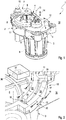
- Fig. 1
- eine isometrische Ansicht einer Stelleinrichtung,
- Fig. 2
- ein vergrößertes Detail II aus
Fig. 1 eines ersten Gehäuseteils bei fehlendem zweitem Gehäuseteil, - Fig. 3
- eine Schnittansicht entsprechend Schnittlinien III in
Fig. 2 im Bereich eines Labyrinthkanals eines Druckausgleichslabyrinths, - Fig. 4
- eine Schnittansicht entsprechend Schnittlinien IV in
Fig. 2 im Bereich einer Umgebungsöffnung des Druckausgleichslabyrinths, - Fig. 5
- eine Schnittansicht entsprechend Schnittlinien V in
Fig. 2 im Bereich einer Innenraumöffnung des Druckausgleichslabyrinths, - Fig. 6
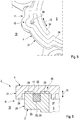
- eine Draufsicht auf das erste Gehäuseteil im Bereich des Druckausgleichslabyrinths, bei einer anderen Ausführungsform,
- Fig. 7
- eine isometrische Ansicht wie in
Fig. 2 , jedoch mit dem zweiten Gehäuseteil, bei einer weiteren Ausführungsform, - Fig. 8
- eine isometrische Ansicht des zweiten Gehäuseteils aus
Fig. 7 im Bereich des Druckausgleichslabyrinths, - Fig. 9
- ein Querschnitt wie in
Fig. 3 , jedoch bei einer anderen Ausführungsform. - Entsprechend
Fig. 1 umfasst eine Stelleinrichtung 1, die zum mechanischen Betätigen einer hier nicht gezeigten Komponente einer hier ebenfalls nicht gezeigten Maschine geeignet und bestimmt ist, ein Gehäuse 2, das ein erstes Gehäuseteil 3 und ein zweites Gehäuseteil 4 aufweist. Im Gehäuse 2 ist ein Innenraum 5 enthalten, in dem ein Elektromotor 6 angeordnet ist. Dieser Elektromotor 6 ist dabei antriebsmäßig mit einem Stellglied 7 gekoppelt, das sich außen am Gehäuse 2 befindet. Beispielsweise kann im Gehäuse 2 bzw. im Innenraum 5 ein Getriebe 8 angeordnet sein, das eine Antriebswelle des Elektromotors 6 mit einer aus dem Gehäuse 2 herausgeführten Welle 9 antriebsmäßig verbindet, an welcher das Stellglied 7 drehfest angebracht ist. Das Stellglied 7 trägt außerdem einen Zapfen 10, der so ausgestaltet ist, dass er mit derjenigen Komponente gekoppelt werden kann, die mit Hilfe der Stelleinrichtung 1 mechanisch betätigt werden soll. - Im Beispiel der
Fig. 1 ist das erste Gehäuseteil 3 topfförmig ausgestaltet und enthält einen wesentlichen Bestandteil, also mehr als 50%, im Beispiel mehr als 75% des Volumens des Innenraums 5. Im Unterschied dazu ist das zweite Gehäuseteil 4 hier als Deckel ausgestaltet, der im montierten Zustand den durch das erste Gehäuseteil 3 gebildeten Topf verschließt. Somit ist der Innenraum 5 von den beiden Gehäuseteilen 3, 4 vollständig eingefasst. Grundsätzlich sind jedoch auch andere Formen für die Gehäuseteile 3, 4 denkbar. Die beiden Gehäuseteile 3, 4 sind hier jeweils einteilig ausgestaltet. Ebenso ist denkbar, zumindest eines der Gehäuseteile 3, 4 mehrteilig auszugestalten. - Jedenfalls handelt es sich bei den beiden Gehäuseteilen 3, 4 um separate Bauteile, die im montierten Zustand des Gehäuses 2 aneinander befestigt sind und die in einem Kontaktbereich 11 aneinander anliegen. Dieser Kontaktbereich 11 läuft in einer Umfangsrichtung 12 des Gehäuses 2 entlang des Innenraums 5 geschlossen um. Die Umfangsrichtung 12 bezieht sich auf eine Rotationsachse 13 des Elektromotors 6. Diese Rotationsachse 13 definiert außerdem eine Axialrichtung 14, die parallel zur Rotationsachse 13 verläuft. Im Beispiel erstreckt sich der Kontaktbereich 11 im Wesentlichen in einer Ebene, die auch als Trennebene bezeichnet werden kann. Zweckmäßig verläuft die Axialrichtung 14 senkrecht zu dieser Trennebene. Zum Schließen des Gehäuses 2 werden die beiden Gehäuseteile 3, 4 zweckmäßig axial aneinander angebracht, so dass eine Montagerichtung des Gehäuses 2 parallel zur Axialrichtung 14 verläuft.
- In
Fig. 2 ist eine Steuereinrichtung 36 angedeutet, die ebenfalls im Innenraum 5 des Gehäuses 2 untergebracht ist. Diese Steuereinrichtung 36 dient zum Ansteuern des Elektromotors 6 und weist mehrere elektrische und/oder elektronische Elemente 37 auf, die beispielsweise eine Sensorik und/oder eine Leistungselektronik bilden können. - Im Kontaktbereich 11 ist ein Druckausgleichslabyrinth 15 ausgebildet, das den Innenraum 5 fluidisch mit einer Umgebung 16 des Gehäuses 2 verbindet. Nachfolgend wird anhand der
Fig. 2 bis 9 näher auf dieses Druckausgleichslabyrinth 15 eingegangen. - Entsprechend den
Fig. 2 bis 9 besitzt das Druckausgleichslabyrinth 15 einen Labyrinthkanal 17, eine Innenraumöffnung 18 und eine Umgebungsöffnung 19. Der Labyrinthkanal 17 erstreckt sich in der Umfangsrichtung 12 entlang eines Teils des Kontaktbereichs 11. Im gezeigten Beispiel erstreckt sich der Labyrinthkanal über weniger als 20% des Kontaktbereichs 11. Die Innenraumöffnung 18 steht mit dem Innenraum 5 fluidisch in Verbindung. Die Umgebungsöffnung 19 steht mit der Umgebung 16 fluidisch in Verbindung. Der Labyrinthkanal 17 verbindet die Innenraumöffnung 18 fluidisch mit der Umgebungsöffnung 19, so dass letztlich der Labyrinthkanal 17 über die Innenraumöffnung 18 mit dem Innenraum 5 und über die Umgebungsöffnung 19 mit der Umgebung 16 jeweils fluidisch verbunden ist. Bemerkenswert ist ferner, dass die Innenraumöffnung 18 und die Umgebungsöffnung 19 in der Umfangsrichtung 12 zueinander versetzt angeordnet sind. - Das erste Gehäuseteil 3 weist im Kontaktbereich 11 einen ersten Randbereich 20 auf, in dem der Labyrinthkanal 17 ausgebildet ist. Das zweite Gehäuseteil 4 weist im Kontaktbereich 11 einen zweiten Randbereich 21 auf. Der zweite Randbereich 21 liegt axial am ersten Randbereich 20 an. In den Schnittansichten der
Fig. 3 bis 5 und 9 dringt der erste Randbereich 20 scheinbar in den zweiten Randbereich 21 axial ein. Dies dient lediglich zur Andeutung einer Verbindung durch Verschweißen oder Plastifizieren zwischen erstem Randbereich 20 und zweitem Randbereich 21, bei der bevorzugt zumindest eine axiale Stirnseite des ersten Randbereichs 20 aufgeheizt wird. Im gezeigten bevorzugten Beispiel ist der Labyrinthkanal 17 ausschließlich bzw. vollständig im ersten Randbereich 20 ausgebildet und durch den vorzugsweise ebenen zweiten Randbereich 21 nur verschlossen. Bei einer nicht gezeigten anderen Ausführungsform kann dagegen vorgesehen sein, dass der Labyrinthkanal 17 teilweise im ersten Randbereich 20 und teilweise im zweiten Randbereich 21 ausgebildet ist. Die beiden Teilbereiche des Labyrinthkanals 17 sind dann an einander zugewandten Seiten jeweils einseitig offen. In diesem Fall wird erst beim Zusammenbau der Gehäuseteile 3, 4 der Labyrinthkanal 17 komplettiert und dabei gleichzeitig auch seitlich verschlossen. - Wie sich insbesondere den
Fig. 3 und 9 entnehmen lässt, besitzt der Labyrinthkanal 17 im Kontaktbereich 11 quer zur Umfangsrichtung 12, die in den Schnittansichten derFig. 3 bis 5 und 9 senkrecht zur Zeichnungsebene verläuft, einen Kanalquerschnitt 22, der radial innen und radial außen vom ersten Randbereich 20 begrenzt ist. Ferner ist dieser Kanalquerschnitt 22 axial vom zweiten Randbereich 21 abgewandt, ebenfalls vom ersten Randbereich 20 begrenzt. Dem zweiten Randbereich 21 axial zugewandt ist der Kanalquerschnitt 22 dagegen vom zweiten Randbereich 21 begrenzt. Bei fehlendem zweitem Gehäuseteil 4 ist der Kanalquerschnitt 22 bzw. der Labyrinthkanal 17 somit axial einseitig offen. Bei angebrachtem zweitem Gehäuseteil 4 ist diese axial offene Seite des Labyrinthkanals 17 durch den zweiten Randbereich 21 axial verschlossen. - Wie sich den
Fig. 2 bis 6 und 9 entnehmen lässt, ist der erste Randbereich 20 zumindest im Bereich des Druckausgleichslabyrinths 15 doppelwandig ausgestaltet, wobei er eine dem Innenraum 5 zugewandte Innenwand 23 und eine vom Innenraum 5 abgewandte Außenwand 24 aufweist. Zwischen Innenwand 23 und Außenwand 24 erstreckt sich der Labyrinthkanal 17. Ferner bilden Innenwand 23 und Außenwand 24 die radiale Begrenzung des Kanalquerschnitts 22 am ersten Randbereich 20. Beim hier gezeigten, bevorzugten Beispiel ist der erste Randbereich 20 ausschließlich im Bereich des Druckausgleichslabyrinths 15 doppelwandig ausgestaltet. - Wie sich insbesondere den
Fig. 3 und9 entnehmen lässt, weist der erste Randbereich 20 im Bereich des Druckausgleichslabyrinths 15, vorzugsweise ausschließlich im Bereich des Druckausgleichslabyrinths 15, einen radial abstehenden Steg 25 auf, der den Kanalquerschnitt 22 axial vom zweiten Randbereich 21 abgewandt begrenzt. Im hier gezeigten, bevorzugten Beispiel steht der Steg 25 radial nach außen ab. Demnach geht im Beispiel die Außenwand 24 von diesem Steg 25 aus. Letztlich verbindet der Steg 25 die Innenwand 23 mit der Außenwand 24. - Bei allen hier gezeigten Ausführungsformen ist die Innenraumöffnung 18 in der Innenwand 23 ausgebildet und außerdem radial orientiert. Ferner lässt sich zumindest
Fig. 5 entnehmen, dass die Innenraumöffnung 18 vom Steg 25 axial beabstandet ist. Dementsprechend befindet sich im Labyrinthkanal 17 am Übergang zur Innenraumöffnung 18 eine Stufe 26. - Gemäß den
Fig. 3 bis 5 und 7 kann am zweiten Randbereich 21 zumindest im Bereich des Druckausgleichslabyrinths 15 ein Innenkragen 27 ausgebildet sein. Der Innenkragen 27 steht im Innenraum 5 radial von der Innenwand 23 beabstandet axial ab und überlappt dabei die Innenraumöffnung 18 axial. Die axiale Überlappung der Innenraumöffnung 18 durch die Innenwand 27 ist inFig. 5 erkennbar. - In den Beispielen der
Fig. 2 bis 5 ist die Umgebungsöffnung 19 in der Außenwand 24 ausgebildet und zweckmäßig radial orientiert. GemäßFig. 4 kann dabei die Umgebungsöffnung 19 zweckmäßig so angeordnet sein, dass sie vom Steg 25 axial beabstandet ist. Somit entsteht im Labyrinthkanal 17 am Übergang zur Umgebungsöffnung 19 ebenfalls eine Stufe 28. Ferner besitzt der zweite Randbereich 21 zumindest im Bereich des Druckausgleichslabyrinths 15 einen Außenkragen 29. Der Außenkragen 29 steht dabei in der Umgebung 16 axial ab und ist dabei radial von der Außenwand 24 beabstandet. Ferner überlappt der Außenkragen 29 die Umgebungsöffnung 19 axial. Diese axiale Überlappung ist inFig. 4 erkennbar. -
Fig. 6 zeigt eine andere Ausführungsform, bei der die Umgebungsöffnung 19 im Steg 25 ausgebildet ist und dabei axial orientiert ist. InFig. 6 ist die Axialrichtung senkrecht zur Zeichnungsebene orientiert. DieFig. 7 und8 zeigen eine weitere alternative Ausführungsform, bei der die Umgebungsöffnung 19 im zweiten Randbereich 21 ausgebildet ist und ebenfalls zweckmäßig axial orientiert ist. InFig. 8 sind der Innenkragen 27 und der Außenkragen 28 nicht dargestellt bzw. nicht vorhanden. Dafür ist inFig. 8 eine Verbindungszone 34 angedeutet, in der die Verbindung der beiden Randbereiche 20, 21 aneinander mittels Klebens, Schweißens oder Plastifizierens stattfindet. - Die
Fig. 2 bis 5 zeigen ein Beispiel, bei dem die Innenraumöffnung 18 im Bereich eines ersten Umfangsendes 30 des Labyrinthkanals 17 angeordnet ist, während die Umgebungsöffnung 19 im Bereich eines zweiten Umfangsendes 31 des Labyrinthkanals 17 angeordnet ist. Hierdurch wird die gesamte Länge des Labyrinthkanals 17 ausgenutzt, die sich in der Umfangsrichtung 12 erstreckt. Ferner ist bei diesem Beispiel vorgesehen, dass der Labyrinthkanal 17 zwischen der Innenraumöffnung 18 und der Umgebungsöffnung19 entlang seiner Erstreckung in der Umfangsrichtung 12 einen im Wesentlichen gleichbleibenden Kanalquerschnitt 22 besitzt. - Im Unterschied dazu zeigen die
Fig. 6 bis 8 Beispiele, bei denen der Labyrinthkanal 17 zwischen seinen beiden Umfangsenden 30, 31 eine radial orientierte Ausbuchtung 32 aufweist. Im Bereich dieser Ausbuchtung 32 ist der Kanalquerschnitt 22 radial vergrößert. Die Ausbuchtung 32 ist bei den hier gezeigten Beispielen radial nach außen orientiert. Ferner ist bei den hier gezeigten Beispielen vorgesehen, dass die Umgebungsöffnung 19 im Bereich dieser Ausbuchtung 32 positioniert ist und dabei axial orientiert ist. InFig. 6 ist die Umgebungsöffnung 19 im Bereich der Ausbuchtung 12 bzw. innerhalb der Ausbuchtung 12 am ersten Randbereich 20, nämlich im Steg 25, ausgebildet. Im Beispiel derFig. 7 und8 ist die Umgebungsöffnung 19 im Bereich der Ausbuchtung 32 bzw. in der Ausbuchtung 32 am zweiten Randbereich 21 ausgebildet. -
Fig. 9 zeigt rein exemplarisch ein Beispiel für eine besondere Ausführungsform, bei der im Druckausgleichslabyrinth 15 ein Filterelement 33 angeordnet ist. Dabei füllt das Filterelement 33 den gesamten Kanalquerschnitt 22 aus, so dass ein nicht näher bezeichneter Druckausgleichspfad, der im Druckausgleichslabyrinth 15 ausgebildet ist und der den Innenraum 5 mit der Umgebung 16 fluidisch verbindet, durch dieses Filterelement 33 führt. Das Filterelement 33 kann gemäß einer vorteilhaften Ausführungsform als gasdurchlässige Membran 35 ausgestaltet sein. Ebenso ist denkbar eine separate gasdurchlässige Membran 35 zusätzlich oder alternativ zum Filterelement 33 vorzusehen.
Claims (15)
- Gehäuse (2) einer elektrischen und/oder elektronischen Komponente (1),- mit einem ersten Gehäuseteil (3), einem zweiten Gehäuseteil (4) und einem Innenraum (5) zur Aufnahme wenigstens eines elektrischen und/oder elektronischen Elements (37),- wobei die beiden Gehäuseteile (3, 4) aneinander befestigt sind und in einem Kontaktbereich (11) aneinander anliegen, der in einer Umfangsrichtung (12) des Gehäuses (2) entlang des Innenraums (5) geschlossen umläuft,- wobei im Kontaktbereich (11) ein Druckausgleichslabyrinth (15) ausgebildet ist, das den Innenraum (5) fluidisch mit einer Umgebung (16) des Gehäuses (2) verbindet.
- Gehäuse (2) nach Anspruch 1,
dadurch gekennzeichnet,
dass das Druckausgleichslabyrinth (15) einen Labyrinthkanal (17) aufweist, der sich in der Umfangsrichtung (12) entlang eines Teils des Kontaktbereichs (11) erstreckt, der über eine Innenraumöffnung (18) mit dem Innenraum (5) fluidisch verbunden ist und der über eine Umgebungsöffnung (19) mit der Umgebung (16) fluidisch verbunden ist, die in der Umfangsrichtung (12) zur Innenraumöffnung (18) versetzt angeordnet ist. - Gehäuse (2) nach Anspruch 2,
dadurch gekennzeichnet,- dass das erste Gehäuseteil (2) im Kontaktbereich (11) einen ersten Randbereich (20) aufweist, der zumindest einen Teil des Labyrinthkanals (17) enthält,- dass das zweite Gehäuseteil (4) im Kontaktbereich (11) einen zweiten Randbereich (21) aufweist, der axial am ersten Randbereich (20) anliegt,- dass der Labyrinthkanal (17) im Kontaktbereich (11) quer zur Umfangsrichtung (12) einen Kanalquerschnitt (22) aufweist, der radial innen und radial außen vom ersten Randbereich (20) begrenzt ist, der an einer vom zweiten Randbereich (21) abgewandten Seite vom ersten Randbereich (20) axial begrenzt ist und der an einer dem zweiten Randbereich (21) zugewandten Seite vom zweiten Randbereich (21) axial begrenzt ist. - Gehäuse (2) nach Anspruch 3,
dadurch gekennzeichnet,
dass der erste Randbereich (20) im Bereich des Druckausgleichslabyrinths (15) doppelwandig ausgestaltet ist und eine dem Innenraum (5) zugewandte Innenwand (23) sowie eine vom Innenraum (5) abgewandte Außenwand (24) aufweist, zwischen denen der Labyrinthkanal (17) ausgebildet ist. - Gehäuse (2) nach Anspruch 4,
dadurch gekennzeichnet,
dass der erste Randbereich (20) im Bereich des Druckausgleichslabyrinths (15) einen radial abstehenden Steg (25) aufweist, der den Kanalquerschnitt (22) gegenüber vom zweiten Randbereich (21) axial begrenzt und von dem die Außenwand (24) oder die Innenwand (23) ausgeht. - Gehäuse (2) nach Anspruch 4 oder 5,
dadurch gekennzeichnet,
dass die Umgebungsöffnung (19) in der Außenwand (24) ausgebildet ist. - Gehäuse (2) nach den Ansprüchen 5 und 6,
dadurch gekennzeichnet,
dass die Umgebungsöffnung (19) radial orientiert ist und axial vom Steg (25) beabstandet ist. - Gehäuse (2) nach Anspruch 6 oder 7,
dadurch gekennzeichnet,
dass am zweiten Randbereich (21) zumindest im Bereich des Druckausgleichslabyrinths (15) ein Außenkragen (29) ausgebildet ist, der in der Umgebung (16) axial absteht, radial von der Außenwand (29) beabstandet ist und die Umgebungsöffnung (19) axial überlappt. - Gehäuse (2) nach einem der Ansprüche 1 bis 8,
dadurch gekennzeichnet,- dass die Umgebungsöffnung (19) im Steg (25) nach Anspruch 5 ausgebildet ist, und/oder- dass die Umgebungsöffnung (19) im zweiten Randbereich (21) nach Anspruch 3 ausgebildet ist. - Gehäuse (2) nach einem der Ansprüche 2 bis 9,
dadurch gekennzeichnet,
dass die Innenraumöffnung (18) im Bereich eines ersten Umfangsendes (30) des Labyrinthkanals (17) angeordnet ist, während die Umgebungsöffnung (19) im Bereich eines zweiten Umfangsendes (31) des Labyrinthkanals (17) angeordnet ist. - Gehäuse (2) nach einem der Ansprüche 1 bis 10,
dadurch gekennzeichnet,- dass im Druckausgleichslabyrinth (15) ein Filterelement (33) und/oder eine gasdurchlässige Membran (35) angeordnet ist, oder- dass im Druckausgleichslabyrinth (15) ein als gasdurchlässige Membran (35) ausgestaltetes Filterelement (33) angeordnet ist. - Gehäuse (2) nach einem der Ansprüche 2 bis 11,
dadurch gekennzeichnet,
dass der Labyrinthkanal (17) zwischen seinen Umfangsenden (30, 31) eine radiale Ausbuchtung (32) aufweist. - Steuereinrichtung (36) mit wenigstens einem elektrischen und/oder elektronischen Element (37) und mit einem Gehäuse (2) nach einem der vorhergehenden Ansprüche, wobei das jeweilige elektrische und/oder elektronische Element (37) im Innenraum (5) des Gehäuses (2) angeordnet ist.
- Stelleinrichtung (1) zum mechanischen Betätigen einer Komponente einer Maschine, vorzugsweise einer Brennkraftmaschine,- mit einem Elektromotor (6) zum Antreiben eines Stellglieds (7) zum Koppeln mit der zu betätigenden Komponente, und- mit einer Steuereinrichtung (36) nach Anspruch 12 zum Ansteuern des Elektromotors (6),- wobei insbesondere vorgesehen sein kann, dass der Elektromotor (6) im Innenraum (5) des Gehäuses (2) angeordnet ist und dass das Stellglied (7) außen am Gehäuse (2) angeordnet ist.
- Stelleinrichtung (1) zum mechanischen Betätigen einer Komponente einer Maschine, vorzugsweise einer Brennkraftmaschine,- mit einem Gehäuse (2) nach einem der Ansprüche 1 bis 13,- mit einem im Innenraum (5) des Gehäuses (2) angeordneten Elektromotor (6) zum Antreiben eines außen am Gehäuse (2) angeordneten Stellglieds (7) zum Koppeln mit der zu betätigenden Komponente.
Applications Claiming Priority (1)
| Application Number | Priority Date | Filing Date | Title |
|---|---|---|---|
| DE102016208276.0A DE102016208276A1 (de) | 2016-05-13 | 2016-05-13 | Stelleinrichtung |
Publications (2)
| Publication Number | Publication Date |
|---|---|
| EP3244714A1 true EP3244714A1 (de) | 2017-11-15 |
| EP3244714B1 EP3244714B1 (de) | 2020-11-25 |
Family
ID=58698989
Family Applications (1)
| Application Number | Title | Priority Date | Filing Date |
|---|---|---|---|
| EP17170094.1A Not-in-force EP3244714B1 (de) | 2016-05-13 | 2017-05-09 | Gehäuse und stelleinrichtung mit gehäuse |
Country Status (2)
| Country | Link |
|---|---|
| EP (1) | EP3244714B1 (de) |
| DE (1) | DE102016208276A1 (de) |
Cited By (1)
| Publication number | Priority date | Publication date | Assignee | Title |
|---|---|---|---|---|
| DE102017212213A1 (de) * | 2017-07-17 | 2019-01-17 | Mahle International Gmbh | Baugruppe mit einem Aktuator |
Families Citing this family (1)
| Publication number | Priority date | Publication date | Assignee | Title |
|---|---|---|---|---|
| DE102022128421A1 (de) * | 2022-10-27 | 2024-05-02 | Bayerische Motoren Werke Aktiengesellschaft | Maschinengehäuseelement mit einer Druckausgleichsnut, Maschinengehäuse und Kraftfahrzeug |
Citations (7)
| Publication number | Priority date | Publication date | Assignee | Title |
|---|---|---|---|---|
| US6273426B1 (en) * | 1999-07-22 | 2001-08-14 | Avaya Technology Corp. | Hydrodynamic seal and a method for providing the same |
| JP2002058128A (ja) * | 2000-05-29 | 2002-02-22 | Yazaki Corp | 電気接続箱 |
| EP1215950A1 (de) * | 2000-12-13 | 2002-06-19 | Siemens Building Technologies AG | Stellantrieb mit einem Gehäuse mit Abdichtung |
| EP1603378A2 (de) * | 2004-06-04 | 2005-12-07 | WABCO GmbH & CO. OHG | Elektronikgehäuse |
| DE202006020493U1 (de) | 2006-07-11 | 2008-10-09 | Rst Rabe-System-Technik Gmbh | Druckausgleichselement |
| EP2273860B1 (de) | 2006-12-22 | 2012-09-19 | Robert Bosch GmbH | Druckausgleichselement für ein Gehäuse und Kraftfahrzeug-Elektrokomponente mit einem solchen Druckausgleichselement |
| DE102011119875A1 (de) | 2011-12-01 | 2013-06-06 | Brose Fahrzeugteile GmbH & Co. Kommanditgesellschaft, Würzburg | Elektromotorischer Stellaktuator, insbesondere einer Feststellbremse |
-
2016
- 2016-05-13 DE DE102016208276.0A patent/DE102016208276A1/de not_active Withdrawn
-
2017
- 2017-05-09 EP EP17170094.1A patent/EP3244714B1/de not_active Not-in-force
Patent Citations (7)
| Publication number | Priority date | Publication date | Assignee | Title |
|---|---|---|---|---|
| US6273426B1 (en) * | 1999-07-22 | 2001-08-14 | Avaya Technology Corp. | Hydrodynamic seal and a method for providing the same |
| JP2002058128A (ja) * | 2000-05-29 | 2002-02-22 | Yazaki Corp | 電気接続箱 |
| EP1215950A1 (de) * | 2000-12-13 | 2002-06-19 | Siemens Building Technologies AG | Stellantrieb mit einem Gehäuse mit Abdichtung |
| EP1603378A2 (de) * | 2004-06-04 | 2005-12-07 | WABCO GmbH & CO. OHG | Elektronikgehäuse |
| DE202006020493U1 (de) | 2006-07-11 | 2008-10-09 | Rst Rabe-System-Technik Gmbh | Druckausgleichselement |
| EP2273860B1 (de) | 2006-12-22 | 2012-09-19 | Robert Bosch GmbH | Druckausgleichselement für ein Gehäuse und Kraftfahrzeug-Elektrokomponente mit einem solchen Druckausgleichselement |
| DE102011119875A1 (de) | 2011-12-01 | 2013-06-06 | Brose Fahrzeugteile GmbH & Co. Kommanditgesellschaft, Würzburg | Elektromotorischer Stellaktuator, insbesondere einer Feststellbremse |
Cited By (2)
| Publication number | Priority date | Publication date | Assignee | Title |
|---|---|---|---|---|
| DE102017212213A1 (de) * | 2017-07-17 | 2019-01-17 | Mahle International Gmbh | Baugruppe mit einem Aktuator |
| DE102017212213B4 (de) * | 2017-07-17 | 2020-08-13 | Mahle International Gmbh | Baugruppe mit einem Aktuator für einen Abgasturbolader oder ein Luftmanagementsystem |
Also Published As
| Publication number | Publication date |
|---|---|
| DE102016208276A1 (de) | 2017-11-16 |
| EP3244714B1 (de) | 2020-11-25 |
Similar Documents
| Publication | Publication Date | Title |
|---|---|---|
| EP2720775B1 (de) | Filterelement | |
| EP3175150B1 (de) | Hydraulische oder pneumatische betätigungsvorrichtung für die betätigung von stellgliedern in einem kraftfahrzeuggetriebe | |
| EP1389486B1 (de) | Ventil zur Steuerung eines Fluidstromes | |
| EP2291717B1 (de) | Druckregelventil | |
| EP2509699B1 (de) | Filterelement und luftfilter | |
| DE102012203624A1 (de) | Abgasturbolader zur Verwendung mit einem Verbrennungsmotor | |
| EP2997249B1 (de) | Abgasventilvorrichtung für eine verbrennungskraftmaschine | |
| DE102012213002A1 (de) | Nockenwellen-Phasensteller mit Dichtungshülse | |
| EP2981700B1 (de) | Luftfilterelement | |
| EP4274066A1 (de) | Fahrzeugaggregat mit druckausgleichselement | |
| EP3240152A1 (de) | Stellvorrichtung | |
| DE102016124370A1 (de) | Sensorvorrichtung sowie Verfahren zum Zusammenbau einer Sensorvorrichtung | |
| EP1736227B1 (de) | Filterdichtsystem | |
| EP2820283B1 (de) | Brennkraftmaschine mit frischgasverteiler | |
| EP3244714B1 (de) | Gehäuse und stelleinrichtung mit gehäuse | |
| DE102012206304A1 (de) | Ladeeinrichtung | |
| DE4437665A1 (de) | Filterelement | |
| EP3239490B1 (de) | Stellvorrichtung | |
| EP2368615A1 (de) | Filtereinrichtung | |
| DE102004025450A1 (de) | Ölwanne für einen Motor und/oder ein Getriebe | |
| EP1183451B1 (de) | Vorrichtung zur rückstellung einer drosselklappe | |
| DE102015222425A1 (de) | Spin-On Wechselfilter | |
| DE102014221452A1 (de) | Steuervorrichtung eines elektrisch angetriebenen Drosselventils | |
| WO2014180707A1 (de) | Zylinderkopfhaube | |
| DE2260081A1 (de) | Elektrische kleinmaschine, insbesondere kleinmotor |
Legal Events
| Date | Code | Title | Description |
|---|---|---|---|
| PUAI | Public reference made under article 153(3) epc to a published international application that has entered the european phase |
Free format text: ORIGINAL CODE: 0009012 |
|
| STAA | Information on the status of an ep patent application or granted ep patent |
Free format text: STATUS: THE APPLICATION HAS BEEN PUBLISHED |
|
| AK | Designated contracting states |
Kind code of ref document: A1 Designated state(s): AL AT BE BG CH CY CZ DE DK EE ES FI FR GB GR HR HU IE IS IT LI LT LU LV MC MK MT NL NO PL PT RO RS SE SI SK SM TR |
|
| AX | Request for extension of the european patent |
Extension state: BA ME |
|
| STAA | Information on the status of an ep patent application or granted ep patent |
Free format text: STATUS: REQUEST FOR EXAMINATION WAS MADE |
|
| 17P | Request for examination filed |
Effective date: 20180511 |
|
| RBV | Designated contracting states (corrected) |
Designated state(s): AL AT BE BG CH CY CZ DE DK EE ES FI FR GB GR HR HU IE IS IT LI LT LU LV MC MK MT NL NO PL PT RO RS SE SI SK SM TR |
|
| STAA | Information on the status of an ep patent application or granted ep patent |
Free format text: STATUS: EXAMINATION IS IN PROGRESS |
|
| 17Q | First examination report despatched |
Effective date: 20190405 |
|
| GRAP | Despatch of communication of intention to grant a patent |
Free format text: ORIGINAL CODE: EPIDOSNIGR1 |
|
| STAA | Information on the status of an ep patent application or granted ep patent |
Free format text: STATUS: GRANT OF PATENT IS INTENDED |
|
| INTG | Intention to grant announced |
Effective date: 20200617 |
|
| GRAS | Grant fee paid |
Free format text: ORIGINAL CODE: EPIDOSNIGR3 |
|
| GRAA | (expected) grant |
Free format text: ORIGINAL CODE: 0009210 |
|
| STAA | Information on the status of an ep patent application or granted ep patent |
Free format text: STATUS: THE PATENT HAS BEEN GRANTED |
|
| AK | Designated contracting states |
Kind code of ref document: B1 Designated state(s): AL AT BE BG CH CY CZ DE DK EE ES FI FR GB GR HR HU IE IS IT LI LT LU LV MC MK MT NL NO PL PT RO RS SE SI SK SM TR |
|
| REG | Reference to a national code |
Ref country code: GB Ref legal event code: FG4D Free format text: NOT ENGLISH |
|
| REG | Reference to a national code |
Ref country code: CH Ref legal event code: EP |
|
| REG | Reference to a national code |
Ref country code: AT Ref legal event code: REF Ref document number: 1339822 Country of ref document: AT Kind code of ref document: T Effective date: 20201215 |
|
| REG | Reference to a national code |
Ref country code: DE Ref legal event code: R096 Ref document number: 502017008328 Country of ref document: DE |
|
| REG | Reference to a national code |
Ref country code: IE Ref legal event code: FG4D Free format text: LANGUAGE OF EP DOCUMENT: GERMAN |
|
| REG | Reference to a national code |
Ref country code: NL Ref legal event code: MP Effective date: 20201125 |
|
| PG25 | Lapsed in a contracting state [announced via postgrant information from national office to epo] |
Ref country code: FI Free format text: LAPSE BECAUSE OF FAILURE TO SUBMIT A TRANSLATION OF THE DESCRIPTION OR TO PAY THE FEE WITHIN THE PRESCRIBED TIME-LIMIT Effective date: 20201125 Ref country code: GR Free format text: LAPSE BECAUSE OF FAILURE TO SUBMIT A TRANSLATION OF THE DESCRIPTION OR TO PAY THE FEE WITHIN THE PRESCRIBED TIME-LIMIT Effective date: 20210226 Ref country code: RS Free format text: LAPSE BECAUSE OF FAILURE TO SUBMIT A TRANSLATION OF THE DESCRIPTION OR TO PAY THE FEE WITHIN THE PRESCRIBED TIME-LIMIT Effective date: 20201125 Ref country code: PT Free format text: LAPSE BECAUSE OF FAILURE TO SUBMIT A TRANSLATION OF THE DESCRIPTION OR TO PAY THE FEE WITHIN THE PRESCRIBED TIME-LIMIT Effective date: 20210325 Ref country code: NO Free format text: LAPSE BECAUSE OF FAILURE TO SUBMIT A TRANSLATION OF THE DESCRIPTION OR TO PAY THE FEE WITHIN THE PRESCRIBED TIME-LIMIT Effective date: 20210225 |
|
| PG25 | Lapsed in a contracting state [announced via postgrant information from national office to epo] |
Ref country code: PL Free format text: LAPSE BECAUSE OF FAILURE TO SUBMIT A TRANSLATION OF THE DESCRIPTION OR TO PAY THE FEE WITHIN THE PRESCRIBED TIME-LIMIT Effective date: 20201125 Ref country code: LV Free format text: LAPSE BECAUSE OF FAILURE TO SUBMIT A TRANSLATION OF THE DESCRIPTION OR TO PAY THE FEE WITHIN THE PRESCRIBED TIME-LIMIT Effective date: 20201125 Ref country code: IS Free format text: LAPSE BECAUSE OF FAILURE TO SUBMIT A TRANSLATION OF THE DESCRIPTION OR TO PAY THE FEE WITHIN THE PRESCRIBED TIME-LIMIT Effective date: 20210325 Ref country code: BG Free format text: LAPSE BECAUSE OF FAILURE TO SUBMIT A TRANSLATION OF THE DESCRIPTION OR TO PAY THE FEE WITHIN THE PRESCRIBED TIME-LIMIT Effective date: 20210225 Ref country code: SE Free format text: LAPSE BECAUSE OF FAILURE TO SUBMIT A TRANSLATION OF THE DESCRIPTION OR TO PAY THE FEE WITHIN THE PRESCRIBED TIME-LIMIT Effective date: 20201125 |
|
| REG | Reference to a national code |
Ref country code: LT Ref legal event code: MG9D |
|
| PG25 | Lapsed in a contracting state [announced via postgrant information from national office to epo] |
Ref country code: HR Free format text: LAPSE BECAUSE OF FAILURE TO SUBMIT A TRANSLATION OF THE DESCRIPTION OR TO PAY THE FEE WITHIN THE PRESCRIBED TIME-LIMIT Effective date: 20201125 |
|
| PG25 | Lapsed in a contracting state [announced via postgrant information from national office to epo] |
Ref country code: SK Free format text: LAPSE BECAUSE OF FAILURE TO SUBMIT A TRANSLATION OF THE DESCRIPTION OR TO PAY THE FEE WITHIN THE PRESCRIBED TIME-LIMIT Effective date: 20201125 Ref country code: RO Free format text: LAPSE BECAUSE OF FAILURE TO SUBMIT A TRANSLATION OF THE DESCRIPTION OR TO PAY THE FEE WITHIN THE PRESCRIBED TIME-LIMIT Effective date: 20201125 Ref country code: CZ Free format text: LAPSE BECAUSE OF FAILURE TO SUBMIT A TRANSLATION OF THE DESCRIPTION OR TO PAY THE FEE WITHIN THE PRESCRIBED TIME-LIMIT Effective date: 20201125 Ref country code: EE Free format text: LAPSE BECAUSE OF FAILURE TO SUBMIT A TRANSLATION OF THE DESCRIPTION OR TO PAY THE FEE WITHIN THE PRESCRIBED TIME-LIMIT Effective date: 20201125 Ref country code: LT Free format text: LAPSE BECAUSE OF FAILURE TO SUBMIT A TRANSLATION OF THE DESCRIPTION OR TO PAY THE FEE WITHIN THE PRESCRIBED TIME-LIMIT Effective date: 20201125 Ref country code: SM Free format text: LAPSE BECAUSE OF FAILURE TO SUBMIT A TRANSLATION OF THE DESCRIPTION OR TO PAY THE FEE WITHIN THE PRESCRIBED TIME-LIMIT Effective date: 20201125 |
|
| REG | Reference to a national code |
Ref country code: DE Ref legal event code: R097 Ref document number: 502017008328 Country of ref document: DE |
|
| PG25 | Lapsed in a contracting state [announced via postgrant information from national office to epo] |
Ref country code: DK Free format text: LAPSE BECAUSE OF FAILURE TO SUBMIT A TRANSLATION OF THE DESCRIPTION OR TO PAY THE FEE WITHIN THE PRESCRIBED TIME-LIMIT Effective date: 20201125 |
|
| PLBE | No opposition filed within time limit |
Free format text: ORIGINAL CODE: 0009261 |
|
| STAA | Information on the status of an ep patent application or granted ep patent |
Free format text: STATUS: NO OPPOSITION FILED WITHIN TIME LIMIT |
|
| PG25 | Lapsed in a contracting state [announced via postgrant information from national office to epo] |
Ref country code: NL Free format text: LAPSE BECAUSE OF FAILURE TO SUBMIT A TRANSLATION OF THE DESCRIPTION OR TO PAY THE FEE WITHIN THE PRESCRIBED TIME-LIMIT Effective date: 20201125 Ref country code: AL Free format text: LAPSE BECAUSE OF FAILURE TO SUBMIT A TRANSLATION OF THE DESCRIPTION OR TO PAY THE FEE WITHIN THE PRESCRIBED TIME-LIMIT Effective date: 20201125 Ref country code: IT Free format text: LAPSE BECAUSE OF FAILURE TO SUBMIT A TRANSLATION OF THE DESCRIPTION OR TO PAY THE FEE WITHIN THE PRESCRIBED TIME-LIMIT Effective date: 20201125 |
|
| 26N | No opposition filed |
Effective date: 20210826 |
|
| PG25 | Lapsed in a contracting state [announced via postgrant information from national office to epo] |
Ref country code: SI Free format text: LAPSE BECAUSE OF FAILURE TO SUBMIT A TRANSLATION OF THE DESCRIPTION OR TO PAY THE FEE WITHIN THE PRESCRIBED TIME-LIMIT Effective date: 20201125 |
|
| REG | Reference to a national code |
Ref country code: CH Ref legal event code: PL |
|
| GBPC | Gb: european patent ceased through non-payment of renewal fee |
Effective date: 20210509 |
|
| PG25 | Lapsed in a contracting state [announced via postgrant information from national office to epo] |
Ref country code: ES Free format text: LAPSE BECAUSE OF FAILURE TO SUBMIT A TRANSLATION OF THE DESCRIPTION OR TO PAY THE FEE WITHIN THE PRESCRIBED TIME-LIMIT Effective date: 20201125 Ref country code: CH Free format text: LAPSE BECAUSE OF NON-PAYMENT OF DUE FEES Effective date: 20210531 Ref country code: LI Free format text: LAPSE BECAUSE OF NON-PAYMENT OF DUE FEES Effective date: 20210531 Ref country code: LU Free format text: LAPSE BECAUSE OF NON-PAYMENT OF DUE FEES Effective date: 20210509 Ref country code: MC Free format text: LAPSE BECAUSE OF FAILURE TO SUBMIT A TRANSLATION OF THE DESCRIPTION OR TO PAY THE FEE WITHIN THE PRESCRIBED TIME-LIMIT Effective date: 20201125 |
|
| REG | Reference to a national code |
Ref country code: BE Ref legal event code: MM Effective date: 20210531 |
|
| PG25 | Lapsed in a contracting state [announced via postgrant information from national office to epo] |
Ref country code: IE Free format text: LAPSE BECAUSE OF NON-PAYMENT OF DUE FEES Effective date: 20210509 Ref country code: GB Free format text: LAPSE BECAUSE OF NON-PAYMENT OF DUE FEES Effective date: 20210509 |
|
| PG25 | Lapsed in a contracting state [announced via postgrant information from national office to epo] |
Ref country code: IS Free format text: LAPSE BECAUSE OF FAILURE TO SUBMIT A TRANSLATION OF THE DESCRIPTION OR TO PAY THE FEE WITHIN THE PRESCRIBED TIME-LIMIT Effective date: 20210325 Ref country code: FR Free format text: LAPSE BECAUSE OF NON-PAYMENT OF DUE FEES Effective date: 20210531 |
|
| PG25 | Lapsed in a contracting state [announced via postgrant information from national office to epo] |
Ref country code: BE Free format text: LAPSE BECAUSE OF NON-PAYMENT OF DUE FEES Effective date: 20210531 |
|
| PG25 | Lapsed in a contracting state [announced via postgrant information from national office to epo] |
Ref country code: HU Free format text: LAPSE BECAUSE OF FAILURE TO SUBMIT A TRANSLATION OF THE DESCRIPTION OR TO PAY THE FEE WITHIN THE PRESCRIBED TIME-LIMIT; INVALID AB INITIO Effective date: 20170509 |
|
| PG25 | Lapsed in a contracting state [announced via postgrant information from national office to epo] |
Ref country code: CY Free format text: LAPSE BECAUSE OF FAILURE TO SUBMIT A TRANSLATION OF THE DESCRIPTION OR TO PAY THE FEE WITHIN THE PRESCRIBED TIME-LIMIT Effective date: 20201125 |
|
| REG | Reference to a national code |
Ref country code: AT Ref legal event code: MM01 Ref document number: 1339822 Country of ref document: AT Kind code of ref document: T Effective date: 20220509 |
|
| PG25 | Lapsed in a contracting state [announced via postgrant information from national office to epo] |
Ref country code: AT Free format text: LAPSE BECAUSE OF NON-PAYMENT OF DUE FEES Effective date: 20220509 |
|
| PG25 | Lapsed in a contracting state [announced via postgrant information from national office to epo] |
Ref country code: MK Free format text: LAPSE BECAUSE OF FAILURE TO SUBMIT A TRANSLATION OF THE DESCRIPTION OR TO PAY THE FEE WITHIN THE PRESCRIBED TIME-LIMIT Effective date: 20201125 |
|
| P01 | Opt-out of the competence of the unified patent court (upc) registered |
Effective date: 20240527 |
|
| PGFP | Annual fee paid to national office [announced via postgrant information from national office to epo] |
Ref country code: DE Payment date: 20240521 Year of fee payment: 8 |
|
| PG25 | Lapsed in a contracting state [announced via postgrant information from national office to epo] |
Ref country code: MT Free format text: LAPSE BECAUSE OF FAILURE TO SUBMIT A TRANSLATION OF THE DESCRIPTION OR TO PAY THE FEE WITHIN THE PRESCRIBED TIME-LIMIT Effective date: 20201125 |
|
| REG | Reference to a national code |
Ref country code: DE Ref legal event code: R119 Ref document number: 502017008328 Country of ref document: DE |
|
| PG25 | Lapsed in a contracting state [announced via postgrant information from national office to epo] |
Ref country code: TR Free format text: LAPSE BECAUSE OF FAILURE TO SUBMIT A TRANSLATION OF THE DESCRIPTION OR TO PAY THE FEE WITHIN THE PRESCRIBED TIME-LIMIT Effective date: 20201125 |
|
| PG25 | Lapsed in a contracting state [announced via postgrant information from national office to epo] |
Ref country code: DE Free format text: LAPSE BECAUSE OF NON-PAYMENT OF DUE FEES Effective date: 20251202 |