EP3244431B1 - Mécanisme de commutation comprenant une fonction de commutation combinée et affichage d'état - Google Patents
Mécanisme de commutation comprenant une fonction de commutation combinée et affichage d'état Download PDFInfo
- Publication number
- EP3244431B1 EP3244431B1 EP17169674.3A EP17169674A EP3244431B1 EP 3244431 B1 EP3244431 B1 EP 3244431B1 EP 17169674 A EP17169674 A EP 17169674A EP 3244431 B1 EP3244431 B1 EP 3244431B1
- Authority
- EP
- European Patent Office
- Prior art keywords
- light guide
- embodied
- light
- installation device
- electrical installation
- Prior art date
- Legal status (The legal status is an assumption and is not a legal conclusion. Google has not performed a legal analysis and makes no representation as to the accuracy of the status listed.)
- Active
Links
- 230000007246 mechanism Effects 0.000 title claims description 31
- 238000009434 installation Methods 0.000 claims description 25
- 238000010616 electrical installation Methods 0.000 claims description 10
- 230000008878 coupling Effects 0.000 claims description 8
- 238000010168 coupling process Methods 0.000 claims description 8
- 238000005859 coupling reaction Methods 0.000 claims description 8
- 230000003287 optical effect Effects 0.000 claims description 8
- 238000005516 engineering process Methods 0.000 claims description 2
- 230000008859 change Effects 0.000 description 3
- 229920003229 poly(methyl methacrylate) Polymers 0.000 description 3
- 239000004926 polymethyl methacrylate Substances 0.000 description 3
- 238000004891 communication Methods 0.000 description 2
- 238000004519 manufacturing process Methods 0.000 description 2
- 238000000034 method Methods 0.000 description 2
- 238000003825 pressing Methods 0.000 description 2
- 230000008569 process Effects 0.000 description 2
- 230000009471 action Effects 0.000 description 1
- 230000000712 assembly Effects 0.000 description 1
- 238000000429 assembly Methods 0.000 description 1
- 239000003086 colorant Substances 0.000 description 1
- 230000002950 deficient Effects 0.000 description 1
- 238000007373 indentation Methods 0.000 description 1
- 238000001746 injection moulding Methods 0.000 description 1
- 239000000463 material Substances 0.000 description 1
- 239000004065 semiconductor Substances 0.000 description 1
- 230000000007 visual effect Effects 0.000 description 1
Images


Classifications
-
- H—ELECTRICITY
- H01—ELECTRIC ELEMENTS
- H01H—ELECTRIC SWITCHES; RELAYS; SELECTORS; EMERGENCY PROTECTIVE DEVICES
- H01H13/00—Switches having rectilinearly-movable operating part or parts adapted for pushing or pulling in one direction only, e.g. push-button switch
- H01H13/02—Details
- H01H13/023—Light-emitting indicators
-
- H—ELECTRICITY
- H01—ELECTRIC ELEMENTS
- H01H—ELECTRIC SWITCHES; RELAYS; SELECTORS; EMERGENCY PROTECTIVE DEVICES
- H01H9/00—Details of switching devices, not covered by groups H01H1/00 - H01H7/00
- H01H9/16—Indicators for switching condition, e.g. "on" or "off"
- H01H9/161—Indicators for switching condition, e.g. "on" or "off" comprising light emitting elements
Definitions
- the invention relates to a switching mechanism with a combined switching function and status display, in particular for devices of an installation bus, the switching mechanism being suitable for actuating a function key of the device.
- an installation bus is, for example, the European installation bus (EIB), which is described in the KNX standard.
- EIB European installation bus
- a building installation device enables individual building installations, such as a lamp or a radiator, to be controlled individually according to a specified operating plan by providing a bus device to each building installation that controls the respective building installation, for example automatically switching a lamp on and off or a Setting the thermostat of a radiator.
- the bus devices can be connected to one another and also to a central configuration device (e.g. ETS) via a building installation bus so that the devices can exchange data with one another and the bus devices can be configured or reconfigured centrally via the configuration device.
- the data exchanged between the bus devices can be, for example, sensor data or control data.
- the underlying bus system is based on the fact that each bus participant has its own microprocessor and is thus independent and independent of a central processor Managed data. For this purpose, an application program with communication objects and parameters is assigned to each bus participant.
- a programming button on the bus device must first be pressed. If the programming button of the bus device is pressed, for example the programming LED of the bus device lights up and the programming mode of the bus device is activated.
- ETS Engineering Tool Software
- KNX commissioning tool the corresponding bus device can then be assigned an individual address.
- bus devices that the programming button and the status display (programming LED) have two separate elements, i.e. to be carried out by a control element and a further display element.
- Other known embodiments of bus devices require additional tools for actuating the programming button.
- German patent application DE102008048708A1 discloses a modular element in the form of an illuminated pushbutton switch for switching and / or displaying operating states of electrical assemblies, the element consisting of a base body with a printed circuit board arranged therein with at least one switch and at least one light source and a contact point arranged on its underside at least one switching element can be latched onto the base body and the base bodies with the latched switching elements can be connected to one another by a connecting element.
- the German patent specification DE69805907T2 discloses a light button switch comprising: a first light pipe the rear end of which is a light interceptor with a bevel and the front end of which is a luminous surface; a button axially receiving the first light guide and having an opening below the light intercepting means; a first light emitting device; a case having an opening on a rear side and a lower side and a hole on a front side; a movable shaft movably and rotatably inserted into the hole punched out on the front of the housing, a protrusion at a front end of the movable shaft being in contact with the button; and at least one rotary switch unit and a push switch unit, wherein the first light guide is shaped as a cylinder or further column, the light intercepting device comprises a beveled surface, wherein the first light emitting device is arranged under the light intercepting device of the first light guide, both switching units with a plurality of stationary contacts electrically in Come into contact and disengage from them
- German utility model DE7814996U1 discloses a pushbutton switch with means for illuminating the pushbutton surface and a manually operated sliding piece, a light guide cap being placed on the sliding piece, which is coated with an opaque layer on its surface with the exception of the area of the pushbutton surface and a light irradiation area.
- the European patent application EP0439814A2 discloses an illuminated pushbutton switch for rear installation in a control panel.
- the illuminated pushbutton switch is provided with a carrier plate.
- a switching device for triggering a switching process is located on the carrier plate.
- a pushbutton element is used to operate the switching device.
- a light source controls the switching process.
- Bus devices with the known programming keys or status displays are therefore complex to operate or to manufacture.
- a switching mechanism with a combined switching function and status display in particular for devices of an installation bus, the switching mechanism being suitable for actuating a function key of the device, the switching mechanism having an axially movable light guide which can be actuated mechanically from the outside of the device for Switching the function key inside the device; and wherein the light guide is designed to visually display the status of the function key.
- a bus participant e.g. actuator, such as alarm detector, window drive; or sensor, such as light switch, motion detector
- a switching mechanism with button function and status display can be provided in a space-saving and functionally reliable manner.
- the switching mechanism can in particular be accommodated in an installation device without changing the external geometry of the device. Farther the touch function is enabled without the aid of a tool.
- a first advantageous embodiment of the invention is that the light guide has a first end and an opposite second end in the axial direction, the first end being designed as an actuating element for an axial mechanical actuation of the light guide.
- the actuating element can be actuated by an operator from the outside of the housing, e.g. by mechanically pressing on the actuating element in the axial direction in order to move the light guide in the axial direction into the interior of the housing in order to mechanically move the opposite second end of the light guide e.g. to be coupled into a microswitch, i.e. to operate the microswitch.
- the microswitch is advantageously located on a circuit board with further components of the corresponding installation device.
- the first end is designed as an optical lens.
- the first end of the light guide has both a button function (e.g. mechanical actuation) and a display function (e.g. status display of the microswitch).
- the status display of the microswitch can e.g. by a corresponding light coding (e.g. light on / light off / flashing light) or a corresponding color light coding (e.g. different light colors for "switch on", "switch off", “switch defective") through the optical lens on the outside of the housing.
- the first end is convex. Due to the convex geometry of the optical lens, the light transported to the outside through the light guide is used to display the status of clearly visible on all sides for an operator.
- the curvature of the optical lens is advantageously designed in such a way that it can be easily and reliably felt by an operator, with sufficient scattering properties.
- Another advantageous embodiment of the invention is that the first end is countersunk in a recess in the housing of the device. In particular, this does not change the external housing geometry.
- a further advantageous embodiment of the invention is that the actuating element is sunk in a chamfered, in particular strongly chamfered, recess of the device housing. This enables good visibility of the status display, despite the fact that the actuating element is countersunk in the housing wall.
- the actuating element can be operated without tools despite the recessed attachment.
- a further advantageous embodiment of the invention is that the second end of the light guide is designed for mechanical coupling with the function key, in particular a micro switch.
- the microswitch is advantageously located on a printed circuit board together with other components (e.g. processor, communication modules) for the functional and control logic of the corresponding installation device. Microswitches are standard components for electronic devices today. They can be used, for example, as "make contacts", “break contacts” or as “changeover contacts” in digital controls or circuits.
- the mechanical coupling of the light guide to the function key takes place, for example, by mechanical contact, in particular by direct mechanical action of the second end of the light guide on the button of the microswitch.
- the second end of the light guide is advantageously matched to the button geometry of the microswitch.
- the second end of the light guide is designed to couple light to display the status of the function key.
- the coupling of light can e.g. by an LED located on the circuit board, which is switched by the microswitch according to its status.
- An LED light emitting diode
- the LED is advantageously arranged spatially next to the microswitch on the circuit board so that the light from the LED can easily be coupled into the second end of the light guide. The light from the LED can easily be coupled into the light guide due to the spatial proximity of the second end.
- the light guide is designed as a workpiece.
- the light guide with its ends can thus be produced easily, in particular in one operation.
- the light guide is e.g. produced by means of an injection molding tool.
- the material can e.g. PMMA (polymethyl methacrylate also called acrylic glass) can be used.
- the light guide is rectangular, in particular with structural elements for distributing coupled light in the direction of the first end.
- the light guide is advantageously a rectangular rod.
- the structural elements can be, for example, a notch and / or a corresponding cut in the workpiece of the light guide.
- the switching mechanism is designed for a user-side, in particular manual, switching input. It is advantageously a matter of a switching mechanism which is sunk or lowered in the housing and which can be actuated by an operator without tools.
- Devices used in electrical installation technology in buildings are, for example, actuators, sockets, switches, dimmers, blinds switches, motion detectors, bus devices, wind sensors, drives for awnings, etc. In modern buildings or houses, these devices can be controlled via an installation bus.
- Such an installation bus is, for example, the European installation bus (EIB), which is described in the KNX standard.
- EIB European installation bus
- These devices usually have display elements (e.g. control lamp) and / or function input elements (e.g. buttons) on their housing.
- FIG 1 shows a first exemplary embodiment for the switching mechanism SM1 according to the invention.
- the switching mechanism SM1 can be used in particular for devices or participants (bus participants) of an installation bus system (eg KNX system).
- KNX system installation bus system
- the representation according to Figure 1 shows a switching mechanism SM1 with a combined switching function and status display, in particular for devices G1 of an installation bus, the switching mechanism SM1 being suitable for actuating a function key, for example a micro button, which is located on a circuit board inside the housing of the device G1.
- the switching mechanism SM1 has an axially movable light guide LL1, which can be actuated mechanically from the outside on the device G1, for switching the function key inside the device.
- the light guide LL1 is axially movable in the direction of movement BR and is advantageously located in a shaft-like recess or recess in the interior of the housing G1.
- the shaft-like recess or recess advantageously has guides or guide elements in order to ensure stable axial guidance of the light guide LL1 in the direction of movement BR.
- the light guide LL1 has a first end EE1, which is designed as an actuation point for mechanical actuation.
- the mechanical actuation can take place, for example, by pressing the actuation point towards the inside of the housing.
- the actuation point is designed for the optical status display of the function key (eg a microswitch.
- the light guide LL1 advantageously has a first end EE1 and an opposite second end ZE1 in the axial direction, the first end EE1 being designed as an actuating element (actuation point) for an axial mechanical actuation of the light guide LL1.
- the second end ZE1 of the light guide LL1 is advantageously designed for mechanical coupling with the function key, in particular a micro-button inside the housing of the device G1.
- the second end ZE1 of the light guide LL1 is advantageously designed for coupling LE1 of light to display the status of the function key of the microswitch.
- the first end EE1 of the light guide LL1 is sunk into a recess V1 in the housing of the device G1.
- the first end EE1 or the actuation point of the light guide LL1 is sunk in a chamfered recess V1 of the device housing.
- the first end EE1 of the light guide LL1 does not protrude beyond the housing geometry of the device G1.
- the representation according to Figure 1 shows a schematic representation of the housing and the housing interior of a device G1, in particular a bus device of an installation bus system (for example KNX system).
- a bus device of an installation bus system for example KNX system.
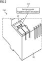
- Figure 2 shows a second exemplary embodiment for the inventive switching mechanism SM2, the first End EE2 of the light guide is sunk in a recess V2 in the housing of the device G2.
- the representation according to Figure 2 shows the first end EE2 of the light guide, which is designed as an actuating element (actuation point) for an axial mechanical movement of the light guide into the interior of the housing, for example to actuate a microswitch or microswitch.
- a micro button can be a programming button or a programming button, for example.
- Figure 3 shows a third exemplary embodiment for the inventive switching mechanism SM3 with a combined switching function and status display, in particular for devices G3 of an installation bus (e.g. KNX bus), the switching mechanism SM3 being suitable for actuating a function key T, e.g. a microswitch MS of device G3.
- the switching mechanism SM3 has an axially movable light guide LL2, which can be actuated mechanically from the outside on the device G3 for switching the function key T inside the device.
- the light guide LL2 is designed for the visual status display of the function key T.
- the light guide LL2 has a first end EE3 and an opposite second end ZE2 in the axial direction, the first end EE3 being designed as an actuating element for an axial mechanical actuation of the light guide LL2.
- the first end EE3 is advantageously designed as an optical lens.
- the first end EE3 is advantageously convex.
- the first end EE3, ie the actuating element for a mechanical axial movement of the light guide LL2, is advantageously sunk into a recess V3 ', V3 " attached to the housing of the device G3.
- the actuating element EE3 is advantageously sunk into a chamfered recess V3 ', V3 "of the device housing, so that the actuating element EE3 does not protrude beyond the external geometry of the housing of the device G3.
- the second end ZE2 of the light guide LL2 is designed for mechanical coupling with the function key T, in particular a microswitch or microswitch MS.
- the second end ZE2 of the light guide LL2 is advantageously designed for coupling LE2 of light to display the status of the function key T or the microswitch MS.
- the second end ZE2 of the light guide LL2 is advantageously designed in such a way that light from a light source LED (e.g. an LED) can be coupled directly into the light guide LL2.
- a light source LED e.g. an LED
- the switching status of the key or the status of the associated micro-button or micro-switch MS is shown in a correspondingly switchable LED (e.g. "light on” for a switched micro switch and "light off” for an unswitched micro switch.
- the microswitch MS and the associated LED are located on a circuit board LP in the interior of the device G3.
- the circuit board has further electronic components for realizing the corresponding function of the device G3.
- the light guide LL2 is advantageously designed to be rectangular in its cross section in the axial direction, in particular with structural elements for distributing the coupled-in light in the direction of the first end EE3.
- the structural elements can be, for example, a notch and / or a corresponding cut in the workpiece of the light guide.
- the switching mechanism SM3 is characterized in particular by a rectangular, axially movable light guide LL2 which does not change the geometry of the housing, but can still be operated without the aid of a tool and is clearly visible from the outside when viewed from the side.
- the correspondingly chamfered indentation (depression) on the housing of the device enables tool-free operation despite the recessed mounting of the light guide.
- Recessed / lowered switching mechanism with combined switching function and status display in particular for devices of an installation bus (e.g. KNX bus), the switching mechanism being suitable for the tool-free actuation of a function key of the device, the switching mechanism having an axially movable, advantageously rectangular, light guide that Can be operated mechanically from the outside of the device without tools, for switching the function key inside the device; and wherein the light guide is designed to visually display the status of the function key, the first end of the light guide advantageously being sunk in a recess, in particular in a chamfered recess, of the housing of the device.
- the switching mechanism can be used in particular for the actuation of micro buttons.
Landscapes
- Switch Cases, Indication, And Locking (AREA)
- Push-Button Switches (AREA)
- Rotary Switch, Piano Key Switch, And Lever Switch (AREA)
- Mechanical Light Control Or Optical Switches (AREA)
Claims (8)
- Appareil d'installation électrique (G1 - G3) pour la technique d'installation de bâtiment, en particulier appareil d'installation électrique pour un bus d'installation, comprenant un boîtier dans lequel sont disposés un bouton-poussoir de fonction (MS, T) et un mécanisme de commutation (SM1 - SM3) à fonction de commutation et affichage d'état combinées,
dans lequel le mécanisme de commutation (SM1 - SM3) est aménagé pour actionner le bouton-poussoir de fonction (MS, T), le mécanisme de commutation (SM1 - SM3) présentant un conducteur de lumière (LL1, LL2) mobile axialement qui peut être actionné mécaniquement par l'extérieur pour commuter le bouton-poussoir de fonction (MS, T) ;
dans lequel le conducteur de lumière (LL1, LL2) est conçu pour l'affichage optique de l'état du bouton-poussoir de fonction (MS, T), dans lequel le conducteur de lumière (LL1, LL2) est conçu en tant qu'une pièce dont la première extrémité (EE1 - EE3) aménagée pour l'actionnement par l'extérieur est disposée enfoncée dans un renfoncement (V1, V2, V3', V3") chanfreiné du boîtier, de telle sorte qu'en dépit de l'enfoncement de la première extrémité (EE1 - EE3), l'affichage d'état est bien visible et la première extrémité (EE1 - EE3) peut être actionnée sans outil. - Appareil d'installation électrique (G1 - G3) selon la revendication 1, dans lequel le conducteur de lumière (LL1, LL2) présente dans le sens axial une première extrémité (EE1 - EE3) et une deuxième extrémité (ZE1 - ZE2) opposée, dans lequel la première extrémité (EE1 - EE3) est conçue en tant qu'élément d'actionnement pour un actionnement mécanique axial du conducteur de lumière (LL1, LL2).
- Appareil d'installation électrique (G1 - G3) selon la revendication 2, dans lequel la première extrémité (EE1 - EE3) est conçue en tant que lentille optique.
- Appareil d'installation électrique (G1 - G3) selon l'une des revendications précédentes, dans lequel la première extrémité (EE1 - EE3) est conçue convexe.
- Appareil d'installation électrique (G1 - G3) selon l'une des revendications précédentes, dans lequel la deuxième extrémité (ZE1 - ZE2) du conducteur de lumière (LL1, LL2) est conçue pour le couplage mécanique avec le bouton-poussoir de fonction, en particulier un micro-bouton-poussoir (microtaster).
- Appareil d'installation électrique (G1 - G3) selon l'une des revendications précédentes, dans lequel la deuxième extrémité du conducteur de lumière (LL1, LL2) est conçue pour le couplage de lumière pour afficher l'état du bouton-poussoir de fonction (MS, T).
- Appareil d'installation électrique (G1 - G3) selon l'une des revendications précédentes, dans lequel le conducteur de lumière (LL1, LL2) est conçu rectangulaire, en particulier avec des éléments structurels pour répartir de la lumière couplée en direction de la première extrémité (EE1 - EE3).
- Appareil d'installation électrique (G1 - G3) selon l'une des revendications précédentes, conçu pour une entrée de commutation côté utilisateur, en particulier manuelle.
Applications Claiming Priority (1)
| Application Number | Priority Date | Filing Date | Title |
|---|---|---|---|
| DE102016208303.1A DE102016208303B3 (de) | 2016-05-13 | 2016-05-13 | Elektrisches Installationsgerät für die Gebäudeinstallationstechnik mit kombinierter Schaltfunktion und Statusanzeige |
Publications (2)
| Publication Number | Publication Date |
|---|---|
| EP3244431A1 EP3244431A1 (fr) | 2017-11-15 |
| EP3244431B1 true EP3244431B1 (fr) | 2020-12-16 |
Family
ID=58709227
Family Applications (1)
| Application Number | Title | Priority Date | Filing Date |
|---|---|---|---|
| EP17169674.3A Active EP3244431B1 (fr) | 2016-05-13 | 2017-05-05 | Mécanisme de commutation comprenant une fonction de commutation combinée et affichage d'état |
Country Status (3)
| Country | Link |
|---|---|
| EP (1) | EP3244431B1 (fr) |
| DE (1) | DE102016208303B3 (fr) |
| ES (1) | ES2859101T3 (fr) |
Families Citing this family (3)
| Publication number | Priority date | Publication date | Assignee | Title |
|---|---|---|---|---|
| DE102019116092B3 (de) | 2019-06-13 | 2020-05-28 | Albrecht Jung Gmbh & Co. Kg | Elektrischer Schalter |
| CN110610825B (zh) * | 2019-09-04 | 2021-09-24 | 山东鲁能力源电器设备有限公司 | 一种加压提示的电力系统用刀闸 |
| DE102021112451B3 (de) | 2021-05-12 | 2022-03-31 | Albrecht Jung Gmbh & Co. Kg | Steckdose mit elektrischem Schalter |
Family Cites Families (6)
| Publication number | Priority date | Publication date | Assignee | Title |
|---|---|---|---|---|
| DE7814996U1 (de) * | 1978-05-18 | 1979-10-25 | Siemens Ag, 1000 Berlin Und 8000 Muenchen | Tastschalter |
| DE9001186U1 (fr) * | 1990-02-02 | 1990-05-17 | S.W.E.C. Schmitt-Walter Engineering Consult, 8025 Unterhaching, De | |
| JP3849221B2 (ja) * | 1997-04-04 | 2006-11-22 | 松下電器産業株式会社 | 照光つまみ付スイッチ |
| DE102008048708A1 (de) * | 2008-09-24 | 2010-03-25 | Eao Automotive Gmbh & Co. Kg | Modulartiges Element |
| TWM351435U (en) * | 2008-10-27 | 2009-02-21 | Inventec Appliances Corp | Reset button structure |
| DE102009051617B3 (de) * | 2009-11-02 | 2011-04-28 | Pas Deutschland Gmbh | Taste für eine Bedienanordnung, sowie Bedienanordnung und Haushaltsgerät |
-
2016
- 2016-05-13 DE DE102016208303.1A patent/DE102016208303B3/de not_active Expired - Fee Related
-
2017
- 2017-05-05 EP EP17169674.3A patent/EP3244431B1/fr active Active
- 2017-05-05 ES ES17169674T patent/ES2859101T3/es active Active
Non-Patent Citations (1)
| Title |
|---|
| None * |
Also Published As
| Publication number | Publication date |
|---|---|
| ES2859101T3 (es) | 2021-10-01 |
| DE102016208303B3 (de) | 2017-08-03 |
| EP3244431A1 (fr) | 2017-11-15 |
Similar Documents
| Publication | Publication Date | Title |
|---|---|---|
| EP1257057B1 (fr) | Elément capteur pour un commutateur capacitif à effleurement | |
| DE19964131A1 (de) | Drehknopf mit Tastfunktion | |
| EP3244431B1 (fr) | Mécanisme de commutation comprenant une fonction de commutation combinée et affichage d'état | |
| EP1232510A1 (fr) | Unite coupe-circuit comportant un support de fusible et un indicateur d'etat de fusible | |
| DE10260305A1 (de) | HMI Einrichtung mit einem optischem Touch Screen | |
| DE60303637T2 (de) | Schalter mit beleuchtetem Knopf | |
| EP2206132B1 (fr) | Actionneur | |
| DE102010047870B4 (de) | Elektrisches Installationsgerät und Set mit Adaptermodulen | |
| DE2741492A1 (de) | Anzeigeeinrichtung fuer elektrische haushaltsgeraete | |
| DD283871A5 (de) | Steuervorrichtung | |
| EP3411893B1 (fr) | Appareil d'installation | |
| DE102007058170B4 (de) | Elektrisches/elektronisches Installationsgerät | |
| DE102016216035A1 (de) | Elektrogerät, Anordnung eines solchen Elektrogeräts mit einer Blende und Verfahren zur Herstellung einer solchen Anordnung | |
| DE102019116092B3 (de) | Elektrischer Schalter | |
| DE102015009066B4 (de) | Anwendungsspezifisch beschriftbarer Bustaster sowie Verfahren zum Beschriften eines solchen Bustasters | |
| DE10163194A1 (de) | Elektromechanische Stufenschaltvorrichtung mit zeitgesteuerten Zusatzfunktionen | |
| EP2469163B1 (fr) | Lampe à actionneurs | |
| EP1298845B1 (fr) | Appareil d'installation | |
| EP0777327A1 (fr) | Interrupteur à bouton-poussoir pour appareils électrodomestiques | |
| EP2779192B1 (fr) | Appareil d'installation électrique/électronique | |
| DE102011015594B4 (de) | Schaltanordnung | |
| DE102007042129B4 (de) | Mehrfachbedienelement | |
| DE102021131460B3 (de) | Steuervorrichtung mit Leuchtmittel | |
| DE102008018383B3 (de) | Eingabeeinrichtung | |
| DE102019110653B4 (de) | Elektrisches/elektronisches Installationssystem |
Legal Events
| Date | Code | Title | Description |
|---|---|---|---|
| PUAI | Public reference made under article 153(3) epc to a published international application that has entered the european phase |
Free format text: ORIGINAL CODE: 0009012 |
|
| STAA | Information on the status of an ep patent application or granted ep patent |
Free format text: STATUS: THE APPLICATION HAS BEEN PUBLISHED |
|
| AK | Designated contracting states |
Kind code of ref document: A1 Designated state(s): AL AT BE BG CH CY CZ DE DK EE ES FI FR GB GR HR HU IE IS IT LI LT LU LV MC MK MT NL NO PL PT RO RS SE SI SK SM TR |
|
| AX | Request for extension of the european patent |
Extension state: BA ME |
|
| STAA | Information on the status of an ep patent application or granted ep patent |
Free format text: STATUS: REQUEST FOR EXAMINATION WAS MADE |
|
| 17P | Request for examination filed |
Effective date: 20180419 |
|
| RBV | Designated contracting states (corrected) |
Designated state(s): AL AT BE BG CH CY CZ DE DK EE ES FI FR GB GR HR HU IE IS IT LI LT LU LV MC MK MT NL NO PL PT RO RS SE SI SK SM TR |
|
| RIC1 | Information provided on ipc code assigned before grant |
Ipc: H01H 9/16 20060101ALI20200706BHEP Ipc: H01H 13/02 20060101ALI20200706BHEP Ipc: H01H 9/18 20060101ALI20200706BHEP Ipc: H01H 21/02 20060101AFI20200706BHEP |
|
| GRAP | Despatch of communication of intention to grant a patent |
Free format text: ORIGINAL CODE: EPIDOSNIGR1 |
|
| STAA | Information on the status of an ep patent application or granted ep patent |
Free format text: STATUS: GRANT OF PATENT IS INTENDED |
|
| INTG | Intention to grant announced |
Effective date: 20200901 |
|
| GRAS | Grant fee paid |
Free format text: ORIGINAL CODE: EPIDOSNIGR3 |
|
| GRAA | (expected) grant |
Free format text: ORIGINAL CODE: 0009210 |
|
| STAA | Information on the status of an ep patent application or granted ep patent |
Free format text: STATUS: THE PATENT HAS BEEN GRANTED |
|
| AK | Designated contracting states |
Kind code of ref document: B1 Designated state(s): AL AT BE BG CH CY CZ DE DK EE ES FI FR GB GR HR HU IE IS IT LI LT LU LV MC MK MT NL NO PL PT RO RS SE SI SK SM TR |
|
| REG | Reference to a national code |
Ref country code: GB Ref legal event code: FG4D Free format text: NOT ENGLISH |
|
| REG | Reference to a national code |
Ref country code: DE Ref legal event code: R096 Ref document number: 502017008666 Country of ref document: DE |
|
| REG | Reference to a national code |
Ref country code: IE Ref legal event code: FG4D Free format text: LANGUAGE OF EP DOCUMENT: GERMAN |
|
| REG | Reference to a national code |
Ref country code: AT Ref legal event code: REF Ref document number: 1346334 Country of ref document: AT Kind code of ref document: T Effective date: 20210115 |
|
| REG | Reference to a national code |
Ref country code: SE Ref legal event code: TRGR |
|
| REG | Reference to a national code |
Ref country code: NL Ref legal event code: FP |
|
| PG25 | Lapsed in a contracting state [announced via postgrant information from national office to epo] |
Ref country code: GR Free format text: LAPSE BECAUSE OF FAILURE TO SUBMIT A TRANSLATION OF THE DESCRIPTION OR TO PAY THE FEE WITHIN THE PRESCRIBED TIME-LIMIT Effective date: 20210317 Ref country code: FI Free format text: LAPSE BECAUSE OF FAILURE TO SUBMIT A TRANSLATION OF THE DESCRIPTION OR TO PAY THE FEE WITHIN THE PRESCRIBED TIME-LIMIT Effective date: 20201216 Ref country code: RS Free format text: LAPSE BECAUSE OF FAILURE TO SUBMIT A TRANSLATION OF THE DESCRIPTION OR TO PAY THE FEE WITHIN THE PRESCRIBED TIME-LIMIT Effective date: 20201216 |
|
| PG25 | Lapsed in a contracting state [announced via postgrant information from national office to epo] |
Ref country code: BG Free format text: LAPSE BECAUSE OF FAILURE TO SUBMIT A TRANSLATION OF THE DESCRIPTION OR TO PAY THE FEE WITHIN THE PRESCRIBED TIME-LIMIT Effective date: 20210316 Ref country code: LV Free format text: LAPSE BECAUSE OF FAILURE TO SUBMIT A TRANSLATION OF THE DESCRIPTION OR TO PAY THE FEE WITHIN THE PRESCRIBED TIME-LIMIT Effective date: 20201216 |
|
| REG | Reference to a national code |
Ref country code: NO Ref legal event code: T2 Effective date: 20201216 |
|
| PG25 | Lapsed in a contracting state [announced via postgrant information from national office to epo] |
Ref country code: HR Free format text: LAPSE BECAUSE OF FAILURE TO SUBMIT A TRANSLATION OF THE DESCRIPTION OR TO PAY THE FEE WITHIN THE PRESCRIBED TIME-LIMIT Effective date: 20201216 |
|
| REG | Reference to a national code |
Ref country code: LT Ref legal event code: MG9D |
|
| PG25 | Lapsed in a contracting state [announced via postgrant information from national office to epo] |
Ref country code: SM Free format text: LAPSE BECAUSE OF FAILURE TO SUBMIT A TRANSLATION OF THE DESCRIPTION OR TO PAY THE FEE WITHIN THE PRESCRIBED TIME-LIMIT Effective date: 20201216 Ref country code: LT Free format text: LAPSE BECAUSE OF FAILURE TO SUBMIT A TRANSLATION OF THE DESCRIPTION OR TO PAY THE FEE WITHIN THE PRESCRIBED TIME-LIMIT Effective date: 20201216 Ref country code: CZ Free format text: LAPSE BECAUSE OF FAILURE TO SUBMIT A TRANSLATION OF THE DESCRIPTION OR TO PAY THE FEE WITHIN THE PRESCRIBED TIME-LIMIT Effective date: 20201216 Ref country code: EE Free format text: LAPSE BECAUSE OF FAILURE TO SUBMIT A TRANSLATION OF THE DESCRIPTION OR TO PAY THE FEE WITHIN THE PRESCRIBED TIME-LIMIT Effective date: 20201216 Ref country code: PT Free format text: LAPSE BECAUSE OF FAILURE TO SUBMIT A TRANSLATION OF THE DESCRIPTION OR TO PAY THE FEE WITHIN THE PRESCRIBED TIME-LIMIT Effective date: 20210416 Ref country code: SK Free format text: LAPSE BECAUSE OF FAILURE TO SUBMIT A TRANSLATION OF THE DESCRIPTION OR TO PAY THE FEE WITHIN THE PRESCRIBED TIME-LIMIT Effective date: 20201216 Ref country code: RO Free format text: LAPSE BECAUSE OF FAILURE TO SUBMIT A TRANSLATION OF THE DESCRIPTION OR TO PAY THE FEE WITHIN THE PRESCRIBED TIME-LIMIT Effective date: 20201216 |
|
| PG25 | Lapsed in a contracting state [announced via postgrant information from national office to epo] |
Ref country code: PL Free format text: LAPSE BECAUSE OF FAILURE TO SUBMIT A TRANSLATION OF THE DESCRIPTION OR TO PAY THE FEE WITHIN THE PRESCRIBED TIME-LIMIT Effective date: 20201216 |
|
| REG | Reference to a national code |
Ref country code: DE Ref legal event code: R097 Ref document number: 502017008666 Country of ref document: DE |
|
| PG25 | Lapsed in a contracting state [announced via postgrant information from national office to epo] |
Ref country code: IS Free format text: LAPSE BECAUSE OF FAILURE TO SUBMIT A TRANSLATION OF THE DESCRIPTION OR TO PAY THE FEE WITHIN THE PRESCRIBED TIME-LIMIT Effective date: 20210416 |
|
| REG | Reference to a national code |
Ref country code: ES Ref legal event code: FG2A Ref document number: 2859101 Country of ref document: ES Kind code of ref document: T3 Effective date: 20211001 |
|
| PLBE | No opposition filed within time limit |
Free format text: ORIGINAL CODE: 0009261 |
|
| STAA | Information on the status of an ep patent application or granted ep patent |
Free format text: STATUS: NO OPPOSITION FILED WITHIN TIME LIMIT |
|
| PG25 | Lapsed in a contracting state [announced via postgrant information from national office to epo] |
Ref country code: AL Free format text: LAPSE BECAUSE OF FAILURE TO SUBMIT A TRANSLATION OF THE DESCRIPTION OR TO PAY THE FEE WITHIN THE PRESCRIBED TIME-LIMIT Effective date: 20201216 |
|
| 26N | No opposition filed |
Effective date: 20210917 |
|
| PG25 | Lapsed in a contracting state [announced via postgrant information from national office to epo] |
Ref country code: DK Free format text: LAPSE BECAUSE OF FAILURE TO SUBMIT A TRANSLATION OF THE DESCRIPTION OR TO PAY THE FEE WITHIN THE PRESCRIBED TIME-LIMIT Effective date: 20201216 |
|
| PG25 | Lapsed in a contracting state [announced via postgrant information from national office to epo] |
Ref country code: MC Free format text: LAPSE BECAUSE OF FAILURE TO SUBMIT A TRANSLATION OF THE DESCRIPTION OR TO PAY THE FEE WITHIN THE PRESCRIBED TIME-LIMIT Effective date: 20201216 Ref country code: LU Free format text: LAPSE BECAUSE OF NON-PAYMENT OF DUE FEES Effective date: 20210505 |
|
| PG25 | Lapsed in a contracting state [announced via postgrant information from national office to epo] |
Ref country code: SI Free format text: LAPSE BECAUSE OF FAILURE TO SUBMIT A TRANSLATION OF THE DESCRIPTION OR TO PAY THE FEE WITHIN THE PRESCRIBED TIME-LIMIT Effective date: 20201216 |
|
| PG25 | Lapsed in a contracting state [announced via postgrant information from national office to epo] |
Ref country code: IE Free format text: LAPSE BECAUSE OF NON-PAYMENT OF DUE FEES Effective date: 20210505 |
|
| PG25 | Lapsed in a contracting state [announced via postgrant information from national office to epo] |
Ref country code: IS Free format text: LAPSE BECAUSE OF FAILURE TO SUBMIT A TRANSLATION OF THE DESCRIPTION OR TO PAY THE FEE WITHIN THE PRESCRIBED TIME-LIMIT Effective date: 20210416 |
|
| PG25 | Lapsed in a contracting state [announced via postgrant information from national office to epo] |
Ref country code: HU Free format text: LAPSE BECAUSE OF FAILURE TO SUBMIT A TRANSLATION OF THE DESCRIPTION OR TO PAY THE FEE WITHIN THE PRESCRIBED TIME-LIMIT; INVALID AB INITIO Effective date: 20170505 |
|
| P01 | Opt-out of the competence of the unified patent court (upc) registered |
Effective date: 20230523 |
|
| PG25 | Lapsed in a contracting state [announced via postgrant information from national office to epo] |
Ref country code: CY Free format text: LAPSE BECAUSE OF FAILURE TO SUBMIT A TRANSLATION OF THE DESCRIPTION OR TO PAY THE FEE WITHIN THE PRESCRIBED TIME-LIMIT Effective date: 20201216 |
|
| PGFP | Annual fee paid to national office [announced via postgrant information from national office to epo] |
Ref country code: NO Payment date: 20230511 Year of fee payment: 7 Ref country code: NL Payment date: 20230511 Year of fee payment: 7 Ref country code: IT Payment date: 20230523 Year of fee payment: 7 Ref country code: FR Payment date: 20230515 Year of fee payment: 7 Ref country code: DE Payment date: 20220620 Year of fee payment: 7 |
|
| PGFP | Annual fee paid to national office [announced via postgrant information from national office to epo] |
Ref country code: TR Payment date: 20230504 Year of fee payment: 7 Ref country code: SE Payment date: 20230508 Year of fee payment: 7 Ref country code: AT Payment date: 20230417 Year of fee payment: 7 |
|
| PGFP | Annual fee paid to national office [announced via postgrant information from national office to epo] |
Ref country code: BE Payment date: 20230519 Year of fee payment: 7 |
|
| PGFP | Annual fee paid to national office [announced via postgrant information from national office to epo] |
Ref country code: GB Payment date: 20230605 Year of fee payment: 7 Ref country code: ES Payment date: 20230823 Year of fee payment: 7 Ref country code: CH Payment date: 20230809 Year of fee payment: 7 |
|
| PG25 | Lapsed in a contracting state [announced via postgrant information from national office to epo] |
Ref country code: MK Free format text: LAPSE BECAUSE OF FAILURE TO SUBMIT A TRANSLATION OF THE DESCRIPTION OR TO PAY THE FEE WITHIN THE PRESCRIBED TIME-LIMIT Effective date: 20201216 |