EP3244044A2 - Procédé de fonctionnement d'un moteur à combustion interne, en particulier en tant que dispositif d'entraînement pour un véhicule automobile - Google Patents
Procédé de fonctionnement d'un moteur à combustion interne, en particulier en tant que dispositif d'entraînement pour un véhicule automobile Download PDFInfo
- Publication number
- EP3244044A2 EP3244044A2 EP17000765.2A EP17000765A EP3244044A2 EP 3244044 A2 EP3244044 A2 EP 3244044A2 EP 17000765 A EP17000765 A EP 17000765A EP 3244044 A2 EP3244044 A2 EP 3244044A2
- Authority
- EP
- European Patent Office
- Prior art keywords
- combustion engine
- internal combustion
- energy
- exhaust gas
- compressed
- Prior art date
- Legal status (The legal status is an assumption and is not a legal conclusion. Google has not performed a legal analysis and makes no representation as to the accuracy of the status listed.)
- Granted
Links
- 238000002485 combustion reaction Methods 0.000 title claims abstract description 187
- 238000000034 method Methods 0.000 title claims abstract description 29
- 238000004146 energy storage Methods 0.000 claims abstract description 35
- 230000006835 compression Effects 0.000 claims description 11
- 238000007906 compression Methods 0.000 claims description 11
- 238000011084 recovery Methods 0.000 claims description 4
- 230000001747 exhibiting effect Effects 0.000 abstract description 3
- 239000000446 fuel Substances 0.000 description 9
- 238000004886 process control Methods 0.000 description 7
- 238000010586 diagram Methods 0.000 description 4
- 238000011161 development Methods 0.000 description 2
- 230000018109 developmental process Effects 0.000 description 2
- 238000011144 upstream manufacturing Methods 0.000 description 2
- 230000001133 acceleration Effects 0.000 description 1
- 230000007423 decrease Effects 0.000 description 1
- 230000001419 dependent effect Effects 0.000 description 1
- 238000013461 design Methods 0.000 description 1
- 230000000694 effects Effects 0.000 description 1
- 238000009396 hybridization Methods 0.000 description 1
- 230000002035 prolonged effect Effects 0.000 description 1
- 210000002023 somite Anatomy 0.000 description 1
- 238000012546 transfer Methods 0.000 description 1
- 238000012795 verification Methods 0.000 description 1
Images


Classifications
-
- F—MECHANICAL ENGINEERING; LIGHTING; HEATING; WEAPONS; BLASTING
- F02—COMBUSTION ENGINES; HOT-GAS OR COMBUSTION-PRODUCT ENGINE PLANTS
- F02D—CONTROLLING COMBUSTION ENGINES
- F02D41/00—Electrical control of supply of combustible mixture or its constituents
- F02D41/0002—Controlling intake air
- F02D41/0007—Controlling intake air for control of turbo-charged or super-charged engines
-
- B—PERFORMING OPERATIONS; TRANSPORTING
- B60—VEHICLES IN GENERAL
- B60L—PROPULSION OF ELECTRICALLY-PROPELLED VEHICLES; SUPPLYING ELECTRIC POWER FOR AUXILIARY EQUIPMENT OF ELECTRICALLY-PROPELLED VEHICLES; ELECTRODYNAMIC BRAKE SYSTEMS FOR VEHICLES IN GENERAL; MAGNETIC SUSPENSION OR LEVITATION FOR VEHICLES; MONITORING OPERATING VARIABLES OF ELECTRICALLY-PROPELLED VEHICLES; ELECTRIC SAFETY DEVICES FOR ELECTRICALLY-PROPELLED VEHICLES
- B60L15/00—Methods, circuits, or devices for controlling the traction-motor speed of electrically-propelled vehicles
- B60L15/20—Methods, circuits, or devices for controlling the traction-motor speed of electrically-propelled vehicles for control of the vehicle or its driving motor to achieve a desired performance, e.g. speed, torque, programmed variation of speed
-
- B—PERFORMING OPERATIONS; TRANSPORTING
- B60—VEHICLES IN GENERAL
- B60T—VEHICLE BRAKE CONTROL SYSTEMS OR PARTS THEREOF; BRAKE CONTROL SYSTEMS OR PARTS THEREOF, IN GENERAL; ARRANGEMENT OF BRAKING ELEMENTS ON VEHICLES IN GENERAL; PORTABLE DEVICES FOR PREVENTING UNWANTED MOVEMENT OF VEHICLES; VEHICLE MODIFICATIONS TO FACILITATE COOLING OF BRAKES
- B60T1/00—Arrangements of braking elements, i.e. of those parts where braking effect occurs specially for vehicles
- B60T1/02—Arrangements of braking elements, i.e. of those parts where braking effect occurs specially for vehicles acting by retarding wheels
- B60T1/10—Arrangements of braking elements, i.e. of those parts where braking effect occurs specially for vehicles acting by retarding wheels by utilising wheel movement for accumulating energy, e.g. driving air compressors
-
- B—PERFORMING OPERATIONS; TRANSPORTING
- B60—VEHICLES IN GENERAL
- B60T—VEHICLE BRAKE CONTROL SYSTEMS OR PARTS THEREOF; BRAKE CONTROL SYSTEMS OR PARTS THEREOF, IN GENERAL; ARRANGEMENT OF BRAKING ELEMENTS ON VEHICLES IN GENERAL; PORTABLE DEVICES FOR PREVENTING UNWANTED MOVEMENT OF VEHICLES; VEHICLE MODIFICATIONS TO FACILITATE COOLING OF BRAKES
- B60T13/00—Transmitting braking action from initiating means to ultimate brake actuator with power assistance or drive; Brake systems incorporating such transmitting means, e.g. air-pressure brake systems
- B60T13/10—Transmitting braking action from initiating means to ultimate brake actuator with power assistance or drive; Brake systems incorporating such transmitting means, e.g. air-pressure brake systems with fluid assistance, drive, or release
- B60T13/58—Combined or convertible systems
- B60T13/585—Combined or convertible systems comprising friction brakes and retarders
- B60T13/586—Combined or convertible systems comprising friction brakes and retarders the retarders being of the electric type
-
- F—MECHANICAL ENGINEERING; LIGHTING; HEATING; WEAPONS; BLASTING
- F02—COMBUSTION ENGINES; HOT-GAS OR COMBUSTION-PRODUCT ENGINE PLANTS
- F02B—INTERNAL-COMBUSTION PISTON ENGINES; COMBUSTION ENGINES IN GENERAL
- F02B21/00—Engines characterised by air-storage chambers
-
- F—MECHANICAL ENGINEERING; LIGHTING; HEATING; WEAPONS; BLASTING
- F02—COMBUSTION ENGINES; HOT-GAS OR COMBUSTION-PRODUCT ENGINE PLANTS
- F02B—INTERNAL-COMBUSTION PISTON ENGINES; COMBUSTION ENGINES IN GENERAL
- F02B29/00—Engines characterised by provision for charging or scavenging not provided for in groups F02B25/00, F02B27/00 or F02B33/00 - F02B39/00; Details thereof
- F02B29/08—Modifying distribution valve timing for charging purposes
-
- F—MECHANICAL ENGINEERING; LIGHTING; HEATING; WEAPONS; BLASTING
- F02—COMBUSTION ENGINES; HOT-GAS OR COMBUSTION-PRODUCT ENGINE PLANTS
- F02B—INTERNAL-COMBUSTION PISTON ENGINES; COMBUSTION ENGINES IN GENERAL
- F02B37/00—Engines characterised by provision of pumps driven at least for part of the time by exhaust
- F02B37/04—Engines with exhaust drive and other drive of pumps, e.g. with exhaust-driven pump and mechanically-driven second pump
- F02B37/10—Engines with exhaust drive and other drive of pumps, e.g. with exhaust-driven pump and mechanically-driven second pump at least one pump being alternatively or simultaneously driven by exhaust and other drive, e.g. by pressurised fluid from a reservoir or an engine-driven pump
-
- F—MECHANICAL ENGINEERING; LIGHTING; HEATING; WEAPONS; BLASTING
- F02—COMBUSTION ENGINES; HOT-GAS OR COMBUSTION-PRODUCT ENGINE PLANTS
- F02B—INTERNAL-COMBUSTION PISTON ENGINES; COMBUSTION ENGINES IN GENERAL
- F02B37/00—Engines characterised by provision of pumps driven at least for part of the time by exhaust
- F02B37/12—Control of the pumps
- F02B37/14—Control of the alternation between or the operation of exhaust drive and other drive of a pump, e.g. dependent on speed
-
- F—MECHANICAL ENGINEERING; LIGHTING; HEATING; WEAPONS; BLASTING
- F02—COMBUSTION ENGINES; HOT-GAS OR COMBUSTION-PRODUCT ENGINE PLANTS
- F02B—INTERNAL-COMBUSTION PISTON ENGINES; COMBUSTION ENGINES IN GENERAL
- F02B39/00—Component parts, details, or accessories relating to, driven charging or scavenging pumps, not provided for in groups F02B33/00 - F02B37/00
- F02B39/02—Drives of pumps; Varying pump drive gear ratio
- F02B39/08—Non-mechanical drives, e.g. fluid drives having variable gear ratio
- F02B39/10—Non-mechanical drives, e.g. fluid drives having variable gear ratio electric
-
- F—MECHANICAL ENGINEERING; LIGHTING; HEATING; WEAPONS; BLASTING
- F02—COMBUSTION ENGINES; HOT-GAS OR COMBUSTION-PRODUCT ENGINE PLANTS
- F02D—CONTROLLING COMBUSTION ENGINES
- F02D13/00—Controlling the engine output power by varying inlet or exhaust valve operating characteristics, e.g. timing
- F02D13/02—Controlling the engine output power by varying inlet or exhaust valve operating characteristics, e.g. timing during engine operation
- F02D13/0223—Variable control of the intake valves only
- F02D13/0226—Variable control of the intake valves only changing valve lift or valve lift and timing
-
- F—MECHANICAL ENGINEERING; LIGHTING; HEATING; WEAPONS; BLASTING
- F02—COMBUSTION ENGINES; HOT-GAS OR COMBUSTION-PRODUCT ENGINE PLANTS
- F02D—CONTROLLING COMBUSTION ENGINES
- F02D13/00—Controlling the engine output power by varying inlet or exhaust valve operating characteristics, e.g. timing
- F02D13/02—Controlling the engine output power by varying inlet or exhaust valve operating characteristics, e.g. timing during engine operation
- F02D13/0269—Controlling the valves to perform a Miller-Atkinson cycle
-
- F—MECHANICAL ENGINEERING; LIGHTING; HEATING; WEAPONS; BLASTING
- F02—COMBUSTION ENGINES; HOT-GAS OR COMBUSTION-PRODUCT ENGINE PLANTS
- F02D—CONTROLLING COMBUSTION ENGINES
- F02D23/00—Controlling engines characterised by their being supercharged
- F02D23/02—Controlling engines characterised by their being supercharged the engines being of fuel-injection type
-
- F—MECHANICAL ENGINEERING; LIGHTING; HEATING; WEAPONS; BLASTING
- F16—ENGINEERING ELEMENTS AND UNITS; GENERAL MEASURES FOR PRODUCING AND MAINTAINING EFFECTIVE FUNCTIONING OF MACHINES OR INSTALLATIONS; THERMAL INSULATION IN GENERAL
- F16D—COUPLINGS FOR TRANSMITTING ROTATION; CLUTCHES; BRAKES
- F16D61/00—Brakes with means for making the energy absorbed available for use
-
- B—PERFORMING OPERATIONS; TRANSPORTING
- B60—VEHICLES IN GENERAL
- B60L—PROPULSION OF ELECTRICALLY-PROPELLED VEHICLES; SUPPLYING ELECTRIC POWER FOR AUXILIARY EQUIPMENT OF ELECTRICALLY-PROPELLED VEHICLES; ELECTRODYNAMIC BRAKE SYSTEMS FOR VEHICLES IN GENERAL; MAGNETIC SUSPENSION OR LEVITATION FOR VEHICLES; MONITORING OPERATING VARIABLES OF ELECTRICALLY-PROPELLED VEHICLES; ELECTRIC SAFETY DEVICES FOR ELECTRICALLY-PROPELLED VEHICLES
- B60L2200/00—Type of vehicles
- B60L2200/36—Vehicles designed to transport cargo, e.g. trucks
-
- B—PERFORMING OPERATIONS; TRANSPORTING
- B60—VEHICLES IN GENERAL
- B60L—PROPULSION OF ELECTRICALLY-PROPELLED VEHICLES; SUPPLYING ELECTRIC POWER FOR AUXILIARY EQUIPMENT OF ELECTRICALLY-PROPELLED VEHICLES; ELECTRODYNAMIC BRAKE SYSTEMS FOR VEHICLES IN GENERAL; MAGNETIC SUSPENSION OR LEVITATION FOR VEHICLES; MONITORING OPERATING VARIABLES OF ELECTRICALLY-PROPELLED VEHICLES; ELECTRIC SAFETY DEVICES FOR ELECTRICALLY-PROPELLED VEHICLES
- B60L2240/00—Control parameters of input or output; Target parameters
- B60L2240/40—Drive Train control parameters
- B60L2240/44—Drive Train control parameters related to combustion engines
- B60L2240/441—Speed
-
- B—PERFORMING OPERATIONS; TRANSPORTING
- B60—VEHICLES IN GENERAL
- B60L—PROPULSION OF ELECTRICALLY-PROPELLED VEHICLES; SUPPLYING ELECTRIC POWER FOR AUXILIARY EQUIPMENT OF ELECTRICALLY-PROPELLED VEHICLES; ELECTRODYNAMIC BRAKE SYSTEMS FOR VEHICLES IN GENERAL; MAGNETIC SUSPENSION OR LEVITATION FOR VEHICLES; MONITORING OPERATING VARIABLES OF ELECTRICALLY-PROPELLED VEHICLES; ELECTRIC SAFETY DEVICES FOR ELECTRICALLY-PROPELLED VEHICLES
- B60L2240/00—Control parameters of input or output; Target parameters
- B60L2240/40—Drive Train control parameters
- B60L2240/44—Drive Train control parameters related to combustion engines
- B60L2240/443—Torque
-
- F—MECHANICAL ENGINEERING; LIGHTING; HEATING; WEAPONS; BLASTING
- F02—COMBUSTION ENGINES; HOT-GAS OR COMBUSTION-PRODUCT ENGINE PLANTS
- F02B—INTERNAL-COMBUSTION PISTON ENGINES; COMBUSTION ENGINES IN GENERAL
- F02B37/00—Engines characterised by provision of pumps driven at least for part of the time by exhaust
- F02B37/12—Control of the pumps
- F02B37/22—Control of the pumps by varying cross-section of exhaust passages or air passages, e.g. by throttling turbine inlets or outlets or by varying effective number of guide conduits
-
- F—MECHANICAL ENGINEERING; LIGHTING; HEATING; WEAPONS; BLASTING
- F02—COMBUSTION ENGINES; HOT-GAS OR COMBUSTION-PRODUCT ENGINE PLANTS
- F02B—INTERNAL-COMBUSTION PISTON ENGINES; COMBUSTION ENGINES IN GENERAL
- F02B37/00—Engines characterised by provision of pumps driven at least for part of the time by exhaust
- F02B37/12—Control of the pumps
- F02B37/24—Control of the pumps by using pumps or turbines with adjustable guide vanes
-
- F—MECHANICAL ENGINEERING; LIGHTING; HEATING; WEAPONS; BLASTING
- F02—COMBUSTION ENGINES; HOT-GAS OR COMBUSTION-PRODUCT ENGINE PLANTS
- F02D—CONTROLLING COMBUSTION ENGINES
- F02D41/00—Electrical control of supply of combustible mixture or its constituents
- F02D41/0002—Controlling intake air
- F02D2041/001—Controlling intake air for engines with variable valve actuation
-
- F—MECHANICAL ENGINEERING; LIGHTING; HEATING; WEAPONS; BLASTING
- F02—COMBUSTION ENGINES; HOT-GAS OR COMBUSTION-PRODUCT ENGINE PLANTS
- F02D—CONTROLLING COMBUSTION ENGINES
- F02D2200/00—Input parameters for engine control
- F02D2200/02—Input parameters for engine control the parameters being related to the engine
- F02D2200/10—Parameters related to the engine output, e.g. engine torque or engine speed
- F02D2200/1002—Output torque
-
- F—MECHANICAL ENGINEERING; LIGHTING; HEATING; WEAPONS; BLASTING
- F02—COMBUSTION ENGINES; HOT-GAS OR COMBUSTION-PRODUCT ENGINE PLANTS
- F02D—CONTROLLING COMBUSTION ENGINES
- F02D2200/00—Input parameters for engine control
- F02D2200/02—Input parameters for engine control the parameters being related to the engine
- F02D2200/10—Parameters related to the engine output, e.g. engine torque or engine speed
- F02D2200/101—Engine speed
-
- F—MECHANICAL ENGINEERING; LIGHTING; HEATING; WEAPONS; BLASTING
- F02—COMBUSTION ENGINES; HOT-GAS OR COMBUSTION-PRODUCT ENGINE PLANTS
- F02D—CONTROLLING COMBUSTION ENGINES
- F02D2200/00—Input parameters for engine control
- F02D2200/50—Input parameters for engine control said parameters being related to the vehicle or its components
- F02D2200/503—Battery correction, i.e. corrections as a function of the state of the battery, its output or its type
-
- F—MECHANICAL ENGINEERING; LIGHTING; HEATING; WEAPONS; BLASTING
- F02—COMBUSTION ENGINES; HOT-GAS OR COMBUSTION-PRODUCT ENGINE PLANTS
- F02D—CONTROLLING COMBUSTION ENGINES
- F02D2200/00—Input parameters for engine control
- F02D2200/70—Input parameters for engine control said parameters being related to the vehicle exterior
- F02D2200/702—Road conditions
-
- F—MECHANICAL ENGINEERING; LIGHTING; HEATING; WEAPONS; BLASTING
- F02—COMBUSTION ENGINES; HOT-GAS OR COMBUSTION-PRODUCT ENGINE PLANTS
- F02D—CONTROLLING COMBUSTION ENGINES
- F02D41/00—Electrical control of supply of combustible mixture or its constituents
- F02D41/0025—Controlling engines characterised by use of non-liquid fuels, pluralities of fuels, or non-fuel substances added to the combustible mixtures
- F02D41/0047—Controlling exhaust gas recirculation [EGR]
- F02D41/0065—Specific aspects of external EGR control
- F02D41/0072—Estimating, calculating or determining the EGR rate, amount or flow
-
- F—MECHANICAL ENGINEERING; LIGHTING; HEATING; WEAPONS; BLASTING
- F02—COMBUSTION ENGINES; HOT-GAS OR COMBUSTION-PRODUCT ENGINE PLANTS
- F02D—CONTROLLING COMBUSTION ENGINES
- F02D41/00—Electrical control of supply of combustible mixture or its constituents
- F02D41/02—Circuit arrangements for generating control signals
- F02D41/04—Introducing corrections for particular operating conditions
- F02D41/10—Introducing corrections for particular operating conditions for acceleration
-
- Y—GENERAL TAGGING OF NEW TECHNOLOGICAL DEVELOPMENTS; GENERAL TAGGING OF CROSS-SECTIONAL TECHNOLOGIES SPANNING OVER SEVERAL SECTIONS OF THE IPC; TECHNICAL SUBJECTS COVERED BY FORMER USPC CROSS-REFERENCE ART COLLECTIONS [XRACs] AND DIGESTS
- Y02—TECHNOLOGIES OR APPLICATIONS FOR MITIGATION OR ADAPTATION AGAINST CLIMATE CHANGE
- Y02T—CLIMATE CHANGE MITIGATION TECHNOLOGIES RELATED TO TRANSPORTATION
- Y02T10/00—Road transport of goods or passengers
- Y02T10/10—Internal combustion engine [ICE] based vehicles
- Y02T10/12—Improving ICE efficiencies
-
- Y—GENERAL TAGGING OF NEW TECHNOLOGICAL DEVELOPMENTS; GENERAL TAGGING OF CROSS-SECTIONAL TECHNOLOGIES SPANNING OVER SEVERAL SECTIONS OF THE IPC; TECHNICAL SUBJECTS COVERED BY FORMER USPC CROSS-REFERENCE ART COLLECTIONS [XRACs] AND DIGESTS
- Y02—TECHNOLOGIES OR APPLICATIONS FOR MITIGATION OR ADAPTATION AGAINST CLIMATE CHANGE
- Y02T—CLIMATE CHANGE MITIGATION TECHNOLOGIES RELATED TO TRANSPORTATION
- Y02T10/00—Road transport of goods or passengers
- Y02T10/60—Other road transportation technologies with climate change mitigation effect
- Y02T10/64—Electric machine technologies in electromobility
-
- Y—GENERAL TAGGING OF NEW TECHNOLOGICAL DEVELOPMENTS; GENERAL TAGGING OF CROSS-SECTIONAL TECHNOLOGIES SPANNING OVER SEVERAL SECTIONS OF THE IPC; TECHNICAL SUBJECTS COVERED BY FORMER USPC CROSS-REFERENCE ART COLLECTIONS [XRACs] AND DIGESTS
- Y02—TECHNOLOGIES OR APPLICATIONS FOR MITIGATION OR ADAPTATION AGAINST CLIMATE CHANGE
- Y02T—CLIMATE CHANGE MITIGATION TECHNOLOGIES RELATED TO TRANSPORTATION
- Y02T10/00—Road transport of goods or passengers
- Y02T10/60—Other road transportation technologies with climate change mitigation effect
- Y02T10/72—Electric energy management in electromobility
Definitions
- the invention relates to a method for operating an internal combustion engine according to the preamble of claim 1, a device with an internal combustion engine according to the preamble of claim 14 and a vehicle, in particular a commercial vehicle, for carrying out the method and / or with the device according to claim 15.
- an energy storage device on a vehicle driven by an internal combustion engine, by means of which the energy generated by the internal combustion engine or the vehicle is temporarily stored, which is then used in certain operating phases of the internal combustion engine for compressing a combustion air flowing through an intake tract of the internal combustion engine.
- the energy storage device may be formed, for example, by a battery, by means of which, for example, generated by a Rekuperationsbremse of the vehicle, electrical energy is cached.
- an electric motor can be operated by means of this intermediately stored electrical energy, by means of which a compressor of an exhaust gas turbocharger of the internal combustion engine is driven. This additional compression of the combustion air or charging of the internal combustion engine is used for a short-term increase in engine power, thus improving the acceleration of the vehicle, in particular during a starting process with the vehicle.
- the object of the invention is to provide a method for operating an internal combustion engine and a device with an internal combustion engine, by means of which the fuel consumption of the internal combustion engine is reduced in a simple and effective manner.
- an energy storage device is provided by means of which, in particular generated by the internal combustion engine and / or by a motor vehicle exhibiting vehicle, stored energy is stored, wherein a control device is provided, by means of which the stored energy is supplied in response to at least one control parameter flowing through an intake manifold of the internal combustion engine combustion air, so that the flowing through the intake air combustion air is compressed.
- a closing time setting device is provided by means of which the closing time of the at least one intake valve of the internal combustion engine can be adjusted, wherein, if the combustion air is not compressed by means of the temporarily stored energy, a basic cycle of the internal combustion engine is set by means of the closing time setting device, in which the at least one intake valve of the internal combustion engine in a crank angle range of 1 ° to 40 ° crank angle, in particular from 10 ° to 40 ° crank angle to UT (bottom dead center) closes, wherein, if the combustion air is compressed by means of the cached energy, to increase the efficiency of the internal combustion engine a cycle of the internal combustion engine is set by means of the closing timing adjusting device, in which the at least one intake valve of the internal combustion engine closes earlier or later compared to the basic cycle.
- a passage cross-section adjusting device is provided according to the invention, by means of which the passage cross-section of a turbine of an exhaust gas turbocharger of the internal combustion engine can be adjusted, wherein, if the combustion air is not compressed by means of the intermediately stored energy, by means of the passage cross-section adjusting device at least one defined basic passage cross-section of the turbine is set, wherein, provided that the combustion air is performed by means of the cached energy, in particular for increasing the efficiency of the internal combustion engine by means of the passage cross-section adjusting device a passage cross-section of the turbine is set, which is greater than a defined amount the basic passage cross section.
- the fuel consumption of the internal combustion engine is effectively reduced because, for example, in the case of earlier or later closing of the at least one intake valve of the internal combustion engine by the, in particular additional, compression of the combustion air by means of the cached energy still a sufficiently high cylinder filling is achieved, although the at least An intake valve of the internal combustion engine compared to the basic cycle sooner or later closes.
- the expansion which is prolonged relative to the compression, increases the internal engine efficiency so that the fuel consumption of the internal combustion engine is reduced.
- the fuel consumption of the internal combustion engine is effectively reduced, since by increasing the passage cross-section of the exhaust gas turbine the exhaust gas pressure before or upstream of the exhaust gas turbine decreases and thus reduces the Ausschiebeaille the internal combustion engine.
- the fuel consumption of the internal combustion engine can also be reduced in a particularly simple manner, since internal combustion engines often already a closing time-adjusting device and / or a passage cross-section actuator is provided.
- the cached energy can also be used to reduce fuel consumption. Effects of hybridization can be realized without corresponding components in the drive train.
- the peak pressure can be limited, whereby the maximum engine torque can be temporarily raised while maintaining a peak pressure limit.
- the process control according to the invention is used only in certain operating situations of the internal combustion engine, for example if the process control according to the invention has a particularly high degree of effectiveness in reducing the fuel consumption of the internal combustion engine.
- the process control according to the invention is also used when the internal combustion engine is in a substantially stationary or unchanged operating state, in particular for a defined long period of time.
- the at least one control parameter is formed by the amount of energy stored by means of the energy storage device in order to effectively control the compression of the combustion air flowing through the intake tract by means of the cached energy.
- the combustion air is not compressed by means of the cached energy. If the amount of energy stored by means of the energy storage device exceeds the defined energy quantity limit value, the combustion air is then compressed by means of the buffered energy.
- the at least one control parameter can also be determined by the current rotational speed of the internal combustion engine and / or by the current torque of the internal combustion engine and / or by the amount of exhaust gas recirculated into the intake tract by means of a, in particular external, exhaust gas recirculation of the internal combustion engine. These parameters also have a significant influence on the effectiveness of the process control according to the invention.
- a gradient determination device is preferably provided, by means of which the gradient of a route section currently and / or in the future traveled with the vehicle can be determined.
- the at least one control parameter is then formed by the determined gradient of the current and / or future traveled by the vehicle route section.
- the slope of the route also has a significant impact on the effectiveness of the process control according to the invention.
- the energy storage device completely emptied or the cached energy are completely used to compress the flowing through the intake air combustion air before a forward gradient of the route, when the energy storage device charged during downhill in the fall in a particularly energy-efficient way with energy can be.
- Such energy-efficient charging can be done for example by means of a Rekuperationsbremse.
- the energy temporarily stored by means of the energy storage device can be formed, for example, by hydraulic and / or pneumatic and / or mechanical and / or electrical energy.
- the energy storage device is preferably formed by an electric battery in order to design the energy storage device in a particularly simple and reliable manner.
- energy recovered and / or generated, in particular electrical energy is temporarily stored by means of the energy storage device by means of an energy recovery device.
- the energy recovery device is formed by a Rekuperationsbremse of the internal combustion engine having vehicle.
- the internal combustion engine has an exhaust gas turbocharger, wherein at least part of the rotational energy of an exhaust gas turbine or of a turbine wheel of the exhaust gas turbocharger is temporarily stored by means of the energy storage device, in particular as a function of the current operating situation of the internal combustion engine. So can the Energy storage device can be charged easily and effectively. For such a charging of the energy storage device, for example, a wastegate of the exhaust gas turbine in an operating situation of the internal combustion engine remain closed, in which the wastegate is otherwise opened. The surplus power possibly occurring in the region of high engine power, which would have been avoided by opening the wastegate, can then be utilized, for example, by electric braking, so that electrical energy is generated.
- the basic passage cross-section of the exhaust gas turbine would then also be set here.
- the wastegate could also be completely dispensed with or no wastegate be provided on the exhaust gas turbine.
- an electric machine in particular an electric generator, is interposed, by means of which the mechanical rotational energy of the exhaust gas turbine can be converted into electrical energy, wherein the electrical energy in the, is stored in particular as a battery, energy storage device is stored.
- the rotational energy of the exhaust gas turbine can be cached in a simple and effective manner by means of the energy storage device.
- the internal combustion engine has an exhaust gas turbocharger, wherein a compressor of the exhaust gas turbocharger can be driven by means of the cached energy.
- a compressor of the exhaust gas turbocharger can be driven by means of the cached energy.
- the control device for driving the compressor by means of the cached electrical energy operated electric machine, in particular an electric motor has to be able to drive the compressor in a particularly simple manner by means of the cached energy.
- the vehicle has a compression device, in particular a compressor for compressing air from the vehicle environment, wherein the energy storage device is formed by a compressed air tank, by means of which Compressor compressed air generated is cached, wherein the air stored in the compressed air tank, in particular downstream of at least one compressor of an exhaust gas turbocharger of the internal combustion engine, introduced into the intake tract of the internal combustion engine is, wherein the control device has at least one control valve, by means of which the amount of introduced into the intake air compressed air is controlled.
- the combustion air flowing through the intake tract of the internal combustion engine can also be compressed in an effective manner.
- the compression device is connected to transmit torque to the internal combustion engine, so that the compression device is driven by means of the internal combustion engine.
- a drive of the compression device is particularly energy-efficient, for example, when the internal combustion engine is in towing mode, in particular when driving downhill with the vehicle having the internal combustion engine.
- the cycle for increasing the efficiency of the internal combustion engine is formed by a Miller cycle.
- the at least one intake valve of the internal combustion engine in a crank angle range of 40 ° to 5 ° crank angle closes before UT to increase the efficiency of the internal combustion engine particularly effective.
- the cycle for increasing the efficiency of the internal combustion engine may also be formed by an Atkinson cycle. It is preferably provided that in the Atkinson cycle, the at least one intake valve of the internal combustion engine closes in a crank angle range of 50 ° to 70 ° crank angle to UT to effectively increase the efficiency of the internal combustion engine.
- the closing time-adjusting device is formed by a cam adjustment and / or by a camshaft adjustment in order to be able to adjust the closing time of the at least one intake valve of the internal combustion engine in a simple and functionally reliable manner.
- the passage cross-section adjusting device is formed by a device for adjusting a turbine geometry of the exhaust gas turbine.
- a device is further proposed, with an internal combustion engine, in particular as a drive device for a vehicle, wherein an energy storage device is provided by means of, in particular generated by the internal combustion engine and / or by a motor vehicle exhibiting vehicle, energy can be stored or cached, wherein a control device is provided, by means of which the stored energy as a function of at least controlled by a control parameter can be supplied to a flowing through an intake manifold of the internal combustion engine combustion air, so that the flowing through the intake air combustion air is compressed.
- an energy storage device is provided by means of, in particular generated by the internal combustion engine and / or by a motor vehicle exhibiting vehicle, energy can be stored or cached
- a control device is provided, by means of which the stored energy as a function of at least controlled by a control parameter can be supplied to a flowing through an intake manifold of the internal combustion engine combustion air, so that the flowing through the intake air combustion air is compressed.
- a closing time setting device is provided by means of which the closing time of the at least one intake valve of the internal combustion engine can be adjusted, wherein, if the combustion air is not compressed by means of the temporarily stored energy, a basic cycle of the internal combustion engine is set by means of the closing time setting device, in which the at least one intake valve of the internal combustion engine in a crank angle range of 1 ° to 40 ° crank angle, in particular from 10 ° to 40 ° crank angle to UT (bottom dead center) closes, wherein, if the combustion air is compressed by means of the cached energy, to increase the efficiency of Internal combustion engine is set by means of the closing timing adjusting device, a cycle of the internal combustion engine, in which the at least one intake valve of the internal combustion engine compared to the basic cycle sooner or later closes.
- a passage cross-section adjusting device is provided according to the invention, by means of which the passage cross-section of a turbine of an exhaust gas turbocharger of the internal combustion engine can be adjusted, wherein, if the combustion air is not compressed by means of the temporarily stored energy, by means of the passage cross-section means at least one defined basic passage cross-section of the turbine is set, wherein, if the combustion air is compressed by means of the cached energy, in particular for increasing the efficiency of the internal combustion engine by means of the passage cross-section adjusting device a passage cross section of the turbine is set, which is greater than in a defined amount the basic passage cross section.
- a vehicle in particular a commercial vehicle, for carrying out the method according to the invention and / or claimed with the device according to the invention.
- the resulting advantages are also identical to the already appreciated advantages of the process control according to the invention and are not repeated here either.
- the exhaust gas line 19 here has a turbine 23 of the exhaust gas turbocharger 15, the turbine wheel of which is driven by the turbine 23 flowing through the exhaust gas 21.
- the turbine 23 has an example here Fig. 2 indicated by dashed lines passage cross-section adjusting device 25, by means of which the passage cross-section of the turbine 23 can be adjusted.
- the passage cross-section adjusting device 25 is formed here by way of example by a device for adjusting a turbine geometry of the turbine 23.
- the device 3 here by way of example also has a torque-transmitting electric machine 29 connected to the exhaust gas turbocharger 15, which can be operated here both in a generator mode of operation and in an engine mode of operation.
- the electric machine 29 In the generator mode, the electric machine 29 is driven by the exhaust gas turbocharger 15, so that the mechanical rotational energy of the exhaust gas turbine 23 of the exhaust gas turbocharger 15 is converted into electrical energy by means of the electric machine 29.
- the electrical energy generated by the electric machine 29 is then stored in a power-transmitting connected to the electric machine 29 battery 31 as an energy storage device.
- the compressor 13 of the exhaust gas turbocharger 15 is driven by means of the electric machine 29.
- the electric machine 29 is then operated here by means stored in the battery 31 or cached electrical energy.
- the combustion air 9 flowing through the intake tract 7 is compressed here by means of the electrical energy stored in the battery 31.
- the device 3 further includes a control unit 33, by means of which the passage cross-section setting device 25, the closing time setting device 18 and the electric machine 29 are controlled by way of example here.
- the closing time adjusting device 18 is here controlled in dependence on the current mode of operation of the electric machine 29. If the compressor 13 of the exhaust gas turbocharger 15 is not driven by means of the electric machine 29, by means of the closing time adjusting device 18, a basic cycle of the internal combustion engine 5 is set in which the at least one inlet valve of the internal combustion engine 5 closes in a crank angle range of 1 ° to 40 ° crank angle, in particular from 10 ° to 40 ° crank angle to UT (bottom dead center).
- a cycle of the internal combustion engine 5 is set by means of the closing timing, in which the at least one inlet valve of the internal combustion engine 5 sooner or later closes compared to the basic cycle. As a result, the efficiency of the internal combustion engine can be increased.
- the cycle for increasing the efficiency is here formed by a Miller cycle, in which the intake valves of the internal combustion engine 5 are closed earlier compared to the basic cycle.
- the intake valves of the internal combustion engine 5 are closed in the Miller cycle in a crank angle range of 40 ° to 5 ° crank angle before UT.
- the cycle for increasing the efficiency of the internal combustion engine 5 could also be formed by an Atkinson cycle in which the intake valves of the internal combustion engine close later compared to the basic cycle.
- the intake valves of the internal combustion engine 5 in the Atkinson cycle are closed in a crank angle range of 50 ° to 70 ° crank angle to UT.
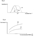
- the curve 37 shows a valve lift h of an intake valve as a function of the crank angle ⁇ of a crankshaft of the internal combustion engine 5 during a Miller cycle.
- the curve 39 shows the valve lift h as a function of the crank angle ⁇ in a basic cycle.
- the curve 41 shows the valve lift h as a function of the crank angle ⁇ in an Atkinson cycle.
- the passage cross-section adjusting device 25 is also controlled here in dependence on the current operating mode of the electric machine 29 by means of the control device 33. If the compressor 13 of the exhaust gas turbocharger 15 is not driven by means of the electric machine 29, a defined basic passage cross-section of the exhaust gas turbine 23 is set by means of the passage cross-section adjusting device 25. If the compressor 13 of the exhaust gas turbocharger 15 is driven by means of the electric machine 29, a passage cross-section of the turbine 23 is set by means of the passage cross-section adjusting device 25, which is greater in a defined degree than the basic passage cross-section. As a result, the efficiency of the internal combustion engine 5 can also be increased.
- Fig. 4 a diagram is shown, from which the difference between a first passage cross-section and a larger than the first passage cross-section formed second passage cross-section of the exhaust gas turbine 23 is illustrated.
- the curve 43 shows a throughput or mass flow m of the exhaust gas 19 through the exhaust gas turbine 23 as a function of a turbine pressure ratio p 1 p 2
- the pressure p 1 here is the exhaust gas pressure immediately in front of the exhaust gas turbine 23.
- the pressure p 2 here is the exhaust pressure immediately after the exhaust gas turbine 23.
- the curve 45 shows the throughput or mass flow m of the Exhaust gas 19 through the exhaust gas turbine 23 in response to a turbine pressure ratio p 1 p 2 at the second set passage cross section of the exhaust gas turbine 23.
- the electric machine 29 is controlled here by way of example as a function of the amount of energy stored by means of the battery 31.
- the control unit 33 is signal-wise connected to the battery 31, so that information about the stored amount of energy is transmitted to the control unit 33.
- the electric machine 29 could also be controlled as a function of a recirculated by an exhaust gas recirculation of the internal combustion engine 5 from the exhaust line 19 in the intake manifold 7 exhaust gas amount as another control parameter.
- the electric machine 29 could optionally also be controlled as a further control parameter as a function of the gradient of a current or future route section traveled by the vehicle 1.
- the electric machine 29 could also be controlled as a function of the current rotational speed of the internal combustion engine 5 and in dependence on the current torque of the internal combustion engine 5 by means of the control device 33 as further control parameters.
- the device 3 here has an air compressor or compressor 47, by means of which air is compressed from the vehicle environment.
- the compressor 47 is here exemplarily torque-transmitting connected to the internal combustion engine 5, so that the compressor 47 is driven by the internal combustion engine 5.
- the compressed by means of the compressor 47 air is stored in a fluidically connected to the compressor 47 compressed air tank 49 as energy storage device.
- the compressed air tank 49 is fluidly connected via a feed line 51 to the intake tract 7 of the internal combustion engine 5, via which the stored compressed air in the compressed air tank 49 compressed air can be introduced at a compressed air inlet 53 of the intake 7 in the intake 7.
- the compressed air introduction region 53 is, viewed in the direction of the combustion air flow, arranged downstream of the compressor 13 and upstream of the heat exchanger 17. By this arrangement, pre-compressed air can be introduced into the intake tract 7, whereby the combustion air 9 flowing through the intake tract 7 is compressed.
- the supply of compressed air into the intake tract 7 is controlled by means of a supply line 51 associated control valve 55, which is technically connected to the control unit 33.
- the control valve 55 may, for example, by a continuously variable Passage valve be formed.
- a check valve 57 is arranged, by means of which a return flow of the compressed combustion air 9 in the direction of the compressor 13 is prevented.
Landscapes
- Engineering & Computer Science (AREA)
- Mechanical Engineering (AREA)
- General Engineering & Computer Science (AREA)
- Chemical & Material Sciences (AREA)
- Combustion & Propulsion (AREA)
- Transportation (AREA)
- Power Engineering (AREA)
- Supercharger (AREA)
- Output Control And Ontrol Of Special Type Engine (AREA)
- Control Of Vehicle Engines Or Engines For Specific Uses (AREA)
Applications Claiming Priority (1)
| Application Number | Priority Date | Filing Date | Title |
|---|---|---|---|
| DE102016005877.3A DE102016005877A1 (de) | 2016-05-13 | 2016-05-13 | Verfahren zum Betreiben einer Brennkraftmaschine, insbesondere als Antriebseinrichtung für ein Fahrzeug |
Publications (3)
| Publication Number | Publication Date |
|---|---|
| EP3244044A2 true EP3244044A2 (fr) | 2017-11-15 |
| EP3244044A3 EP3244044A3 (fr) | 2018-11-21 |
| EP3244044B1 EP3244044B1 (fr) | 2020-07-22 |
Family
ID=58714861
Family Applications (1)
| Application Number | Title | Priority Date | Filing Date |
|---|---|---|---|
| EP17000765.2A Active EP3244044B1 (fr) | 2016-05-13 | 2017-05-04 | Procédé de fonctionnement d'un moteur à combustion interne, en particulier en tant que dispositif d'entraînement pour un véhicule automobile |
Country Status (2)
| Country | Link |
|---|---|
| EP (1) | EP3244044B1 (fr) |
| DE (1) | DE102016005877A1 (fr) |
Families Citing this family (1)
| Publication number | Priority date | Publication date | Assignee | Title |
|---|---|---|---|---|
| DE102019114932A1 (de) * | 2019-06-04 | 2020-12-10 | Ihi Charging Systems International Gmbh | Verfahren für eine Verbrennungskraftmaschine mit einem Abgasturbolader und Abgasturboladersystem, insbesondere für eine Verbrennungskraftmaschine |
Family Cites Families (14)
| Publication number | Priority date | Publication date | Assignee | Title |
|---|---|---|---|---|
| FR2790036B1 (fr) * | 1999-02-23 | 2001-05-18 | Renault | Procede de commande d'un turbocompresseur a geometrie variable, notamment pour moteur diesel |
| DE10225305A1 (de) * | 2002-06-07 | 2003-12-18 | Bosch Gmbh Robert | Verfahren und Vorrichtung zur Steuerung einer Brennkraftmaschine |
| DE10239110B4 (de) * | 2002-08-27 | 2004-08-19 | Caterpillar Motoren Gmbh & Co. Kg | Aufladesystem für eine Brennkraftmaschine |
| DE602004010439T2 (de) * | 2004-05-07 | 2008-10-23 | Honeywell International Inc. | Verfahren zum betrieb eines elektrisch unterstützten turboladers und verstärkungsvorrichtung |
| DE102006034825A1 (de) * | 2005-08-09 | 2007-02-15 | Robert Bosch Gmbh | Vorrichtung zur Energieumsetzung |
| US20070277793A1 (en) * | 2006-06-01 | 2007-12-06 | Edward Lawrence Warren | Method for operating an internal combustion engine |
| DE102007027968A1 (de) * | 2007-06-19 | 2009-01-02 | Knorr-Bremse Systeme für Nutzfahrzeuge GmbH | Verfahren und Vorrichtung zum Steigern der Motorbremsleistung einer Hubkolben-Verbrennungsmaschine eines Fahrzeugs, insbesondere eines Motors in Dieselausführung |
| EP2006516A1 (fr) * | 2007-06-22 | 2008-12-24 | ABB Turbo Systems AG | Turbocompresseur à gaz d'échappement |
| JP4512617B2 (ja) * | 2007-06-26 | 2010-07-28 | 日立オートモティブシステムズ株式会社 | 内燃機関の制御装置および方法 |
| CH701760A8 (de) * | 2009-09-10 | 2012-02-29 | Eth Zuerich | Turboaufgeladene Hubkolbenkraftmaschine mit angeschlossenem Drucktank zur Turbolochüberbrückung und Verfahren zum Betrieb derselben. |
| CN102933816B (zh) * | 2011-06-10 | 2015-04-29 | 丰田自动车株式会社 | 火花点火式内燃机 |
| DE102011122442A1 (de) * | 2011-12-24 | 2013-06-27 | Volkswagen Aktiengesellschaft | Verfahren zum Betreiben eines Verbrennungsmotors |
| DE102014208092A1 (de) * | 2014-04-29 | 2015-10-29 | Mahle International Gmbh | Verfahren zum Betrieb eines Kraftfahrzeugs |
| DE102014221331A1 (de) * | 2014-10-21 | 2016-04-21 | Ford Global Technologies, Llc | Verfahren zum Betreiben einer aufgeladenen Brennkraftmaschine und Brennkraftmaschine zur Durchführung eines derartigen Verfahrens umfassend eine variable Turbine |
-
2016
- 2016-05-13 DE DE102016005877.3A patent/DE102016005877A1/de not_active Withdrawn
-
2017
- 2017-05-04 EP EP17000765.2A patent/EP3244044B1/fr active Active
Non-Patent Citations (1)
| Title |
|---|
| None |
Also Published As
| Publication number | Publication date |
|---|---|
| DE102016005877A1 (de) | 2017-11-16 |
| EP3244044A3 (fr) | 2018-11-21 |
| EP3244044B1 (fr) | 2020-07-22 |
Similar Documents
| Publication | Publication Date | Title |
|---|---|---|
| EP2167799B1 (fr) | Procédé et dispositif pour augmenter la puissance de freinage moteur d'un moteur à combustion interne à piston alternatif dans un véhicule, en particulier d'un moteur diesel | |
| DE102008036284B4 (de) | Antriebsstrang für ein Kraftfahrzeug | |
| DE112005001946T5 (de) | Öffnungs/Schliesssteuerung einer Einlass- und Auslassverbindungsschaltung | |
| EP3026237A1 (fr) | Procédé et dispositif de fonctionnement d'un turbocompresseur à moteur éléctrique d'un véhicule automobile | |
| WO2016058739A1 (fr) | Dispositif de suralimentation pour moteur à combustion interne et procédé de fonctionnement du dispositif de suralimentation | |
| DE102013106643A1 (de) | Motoranordnung mit Energierückgewinnung aus dem Abgas | |
| DE102007052118A1 (de) | Verfahren zur Steuerung der Leistungsübertragung in einem Antriebsstrang mit einem Turbocompoundsystem und Antriebsstrang | |
| DE102018207413A1 (de) | Verfahren zum Betreiben einer Motorbremse in einer Brennkraftmaschine | |
| EP2166211A1 (fr) | Moteur à combustion interne avec recirculation des gaz d'échappement | |
| DE102008048366A1 (de) | Anordnung zur Frischgasversorgung einer turboaufgeladenen Verbrennungsmaschine und Verfahren zum Steuern der Anordnung | |
| WO2016146229A1 (fr) | Système pour moteur à combustion interne, moteur à combustion interne et procédé pour faire fonctionner un système pour moteur à combustion interne | |
| WO2010106171A1 (fr) | Procédé et dispositif pour commander un dispositif d'entraînement hybride | |
| EP3244044B1 (fr) | Procédé de fonctionnement d'un moteur à combustion interne, en particulier en tant que dispositif d'entraînement pour un véhicule automobile | |
| WO2017108652A1 (fr) | Procédé et dispositif pour faire fonctionner un véhicule automobile à entraînement hybride | |
| DE102012222107A1 (de) | Verfahren zum Steuern einer Abgasrückführung | |
| DE102015015101B3 (de) | Verfahren zum Betreiben einer Antriebseinrichtung sowie entsprechende Antriebseinrichtung | |
| DE102018220383A1 (de) | Verfahren zur Regulierung einer Temperatur in einem Abgassystem | |
| DE102019200418A1 (de) | Verfahren zur Beeinflussung der Temperatur eines Abgases, Hybridmotoranordnung und Hybridelektrokraftfahrzeug | |
| DE102019112314A1 (de) | Verfahren zum Betreiben einer Antriebseinrichtung eines Kraftfahrzeugs, Antriebseinrichtung für ein Kraftfahrzeug sowie Kraftfahrzeug | |
| DE102019119260A1 (de) | Konditioniervorrichtung für ein Kraftfahrzeug, Kraftfahrzeug mit einer Konditioniervorrichtung und Verfahren zum Betreiben einer Konditioniervorrichtung in einem Kraftfahrzeug | |
| DE10324958B4 (de) | Verfahren und Vorrichtung zum Betreiben einer Brennkraftmaschine eines Fahrzeugs | |
| DE102009051261A1 (de) | Verfahren zum Betreiben einer Motorbremse eines Kraftwagens | |
| DE102007000312B4 (de) | Steuergerät eines Fahrzeugverbrennungsmotorsystems | |
| DE102017005238A1 (de) | Hybridantrieb | |
| DE102010025196B4 (de) | Verfahren zum Betreiben einer Brennkraftmaschine mit Nutzturbine in einem Wastegate-Kanal und Brennkraftmaschine mit Nutzturbine in einem Wastegate-Kanal |
Legal Events
| Date | Code | Title | Description |
|---|---|---|---|
| PUAI | Public reference made under article 153(3) epc to a published international application that has entered the european phase |
Free format text: ORIGINAL CODE: 0009012 |
|
| STAA | Information on the status of an ep patent application or granted ep patent |
Free format text: STATUS: THE APPLICATION HAS BEEN PUBLISHED |
|
| AK | Designated contracting states |
Kind code of ref document: A2 Designated state(s): AL AT BE BG CH CY CZ DE DK EE ES FI FR GB GR HR HU IE IS IT LI LT LU LV MC MK MT NL NO PL PT RO RS SE SI SK SM TR |
|
| AX | Request for extension of the european patent |
Extension state: BA ME |
|
| RIC1 | Information provided on ipc code assigned before grant |
Ipc: B60L 7/00 20060101ALI20180525BHEP Ipc: B60T 1/10 20060101ALI20180525BHEP Ipc: F02B 39/10 20060101ALI20180525BHEP Ipc: F16D 61/00 20060101ALI20180525BHEP Ipc: B60T 13/58 20060101ALI20180525BHEP Ipc: F02D 13/02 20060101ALI20180525BHEP Ipc: F02D 21/08 20060101ALN20180525BHEP Ipc: F02D 41/10 20060101ALI20180525BHEP Ipc: F02B 21/00 20060101ALI20180525BHEP Ipc: F02B 37/14 20060101ALI20180525BHEP Ipc: F02B 37/22 20060101ALN20180525BHEP Ipc: B60L 15/20 20060101ALI20180525BHEP Ipc: F02B 37/24 20060101ALI20180525BHEP Ipc: F02D 33/02 20060101AFI20180525BHEP Ipc: F02B 37/10 20060101ALI20180525BHEP Ipc: F02B 29/08 20060101ALI20180525BHEP Ipc: F02D 23/02 20060101ALI20180525BHEP |
|
| PUAL | Search report despatched |
Free format text: ORIGINAL CODE: 0009013 |
|
| AK | Designated contracting states |
Kind code of ref document: A3 Designated state(s): AL AT BE BG CH CY CZ DE DK EE ES FI FR GB GR HR HU IE IS IT LI LT LU LV MC MK MT NL NO PL PT RO RS SE SI SK SM TR |
|
| AX | Request for extension of the european patent |
Extension state: BA ME |
|
| RIC1 | Information provided on ipc code assigned before grant |
Ipc: F02D 33/02 20060101AFI20181015BHEP Ipc: F02B 37/24 20060101ALI20181015BHEP Ipc: F02B 39/10 20060101ALI20181015BHEP Ipc: B60T 13/58 20060101ALI20181015BHEP Ipc: F02B 37/22 20060101ALN20181015BHEP Ipc: F02B 37/14 20060101ALI20181015BHEP Ipc: F02D 13/02 20060101ALI20181015BHEP Ipc: F02D 21/08 20060101ALN20181015BHEP Ipc: F16D 61/00 20060101ALI20181015BHEP Ipc: B60L 15/20 20060101ALI20181015BHEP Ipc: B60T 1/10 20060101ALI20181015BHEP Ipc: F02B 21/00 20060101ALI20181015BHEP Ipc: F02D 41/10 20060101ALI20181015BHEP Ipc: F02B 29/08 20060101ALI20181015BHEP Ipc: F02D 23/02 20060101ALI20181015BHEP Ipc: F02B 37/10 20060101ALI20181015BHEP Ipc: B60L 7/00 20060101ALI20181015BHEP |
|
| STAA | Information on the status of an ep patent application or granted ep patent |
Free format text: STATUS: REQUEST FOR EXAMINATION WAS MADE |
|
| 17P | Request for examination filed |
Effective date: 20190521 |
|
| RBV | Designated contracting states (corrected) |
Designated state(s): AL AT BE BG CH CY CZ DE DK EE ES FI FR GB GR HR HU IE IS IT LI LT LU LV MC MK MT NL NO PL PT RO RS SE SI SK SM TR |
|
| RAP1 | Party data changed (applicant data changed or rights of an application transferred) |
Owner name: MAN TRUCK & BUS SE |
|
| RIC1 | Information provided on ipc code assigned before grant |
Ipc: B60L 15/20 20060101ALI20191220BHEP Ipc: F02D 13/02 20060101ALI20191220BHEP Ipc: F16D 61/00 20060101ALI20191220BHEP Ipc: F02D 33/02 20060101AFI20191220BHEP Ipc: F02B 29/08 20060101ALI20191220BHEP Ipc: B60T 13/58 20060101ALI20191220BHEP Ipc: B60L 7/00 20060101ALI20191220BHEP Ipc: F02B 37/10 20060101ALI20191220BHEP Ipc: F02D 23/02 20060101ALI20191220BHEP Ipc: F02D 21/08 20060101ALN20191220BHEP Ipc: F02B 37/14 20060101ALI20191220BHEP Ipc: F02B 37/22 20060101ALN20191220BHEP Ipc: F02D 41/10 20060101ALI20191220BHEP Ipc: F02B 21/00 20060101ALI20191220BHEP Ipc: F02B 39/10 20060101ALI20191220BHEP Ipc: B60T 1/10 20060101ALI20191220BHEP Ipc: F02B 37/24 20060101ALI20191220BHEP |
|
| GRAP | Despatch of communication of intention to grant a patent |
Free format text: ORIGINAL CODE: EPIDOSNIGR1 |
|
| STAA | Information on the status of an ep patent application or granted ep patent |
Free format text: STATUS: GRANT OF PATENT IS INTENDED |
|
| INTG | Intention to grant announced |
Effective date: 20200212 |
|
| GRAS | Grant fee paid |
Free format text: ORIGINAL CODE: EPIDOSNIGR3 |
|
| GRAA | (expected) grant |
Free format text: ORIGINAL CODE: 0009210 |
|
| STAA | Information on the status of an ep patent application or granted ep patent |
Free format text: STATUS: THE PATENT HAS BEEN GRANTED |
|
| AK | Designated contracting states |
Kind code of ref document: B1 Designated state(s): AL AT BE BG CH CY CZ DE DK EE ES FI FR GB GR HR HU IE IS IT LI LT LU LV MC MK MT NL NO PL PT RO RS SE SI SK SM TR |
|
| REG | Reference to a national code |
Ref country code: GB Ref legal event code: FG4D Free format text: NOT ENGLISH |
|
| REG | Reference to a national code |
Ref country code: CH Ref legal event code: EP |
|
| REG | Reference to a national code |
Ref country code: DE Ref legal event code: R096 Ref document number: 502017006291 Country of ref document: DE |
|
| REG | Reference to a national code |
Ref country code: AT Ref legal event code: REF Ref document number: 1293601 Country of ref document: AT Kind code of ref document: T Effective date: 20200815 |
|
| REG | Reference to a national code |
Ref country code: IE Ref legal event code: FG4D Free format text: LANGUAGE OF EP DOCUMENT: GERMAN |
|
| REG | Reference to a national code |
Ref country code: NL Ref legal event code: FP |
|
| REG | Reference to a national code |
Ref country code: SE Ref legal event code: TRGR |
|
| REG | Reference to a national code |
Ref country code: LT Ref legal event code: MG4D |
|
| PG25 | Lapsed in a contracting state [announced via postgrant information from national office to epo] |
Ref country code: HR Free format text: LAPSE BECAUSE OF FAILURE TO SUBMIT A TRANSLATION OF THE DESCRIPTION OR TO PAY THE FEE WITHIN THE PRESCRIBED TIME-LIMIT Effective date: 20200722 Ref country code: BG Free format text: LAPSE BECAUSE OF FAILURE TO SUBMIT A TRANSLATION OF THE DESCRIPTION OR TO PAY THE FEE WITHIN THE PRESCRIBED TIME-LIMIT Effective date: 20201022 Ref country code: PT Free format text: LAPSE BECAUSE OF FAILURE TO SUBMIT A TRANSLATION OF THE DESCRIPTION OR TO PAY THE FEE WITHIN THE PRESCRIBED TIME-LIMIT Effective date: 20201123 Ref country code: FI Free format text: LAPSE BECAUSE OF FAILURE TO SUBMIT A TRANSLATION OF THE DESCRIPTION OR TO PAY THE FEE WITHIN THE PRESCRIBED TIME-LIMIT Effective date: 20200722 Ref country code: GR Free format text: LAPSE BECAUSE OF FAILURE TO SUBMIT A TRANSLATION OF THE DESCRIPTION OR TO PAY THE FEE WITHIN THE PRESCRIBED TIME-LIMIT Effective date: 20201023 Ref country code: NO Free format text: LAPSE BECAUSE OF FAILURE TO SUBMIT A TRANSLATION OF THE DESCRIPTION OR TO PAY THE FEE WITHIN THE PRESCRIBED TIME-LIMIT Effective date: 20201022 Ref country code: ES Free format text: LAPSE BECAUSE OF FAILURE TO SUBMIT A TRANSLATION OF THE DESCRIPTION OR TO PAY THE FEE WITHIN THE PRESCRIBED TIME-LIMIT Effective date: 20200722 Ref country code: LT Free format text: LAPSE BECAUSE OF FAILURE TO SUBMIT A TRANSLATION OF THE DESCRIPTION OR TO PAY THE FEE WITHIN THE PRESCRIBED TIME-LIMIT Effective date: 20200722 |
|
| PG25 | Lapsed in a contracting state [announced via postgrant information from national office to epo] |
Ref country code: LV Free format text: LAPSE BECAUSE OF FAILURE TO SUBMIT A TRANSLATION OF THE DESCRIPTION OR TO PAY THE FEE WITHIN THE PRESCRIBED TIME-LIMIT Effective date: 20200722 Ref country code: RS Free format text: LAPSE BECAUSE OF FAILURE TO SUBMIT A TRANSLATION OF THE DESCRIPTION OR TO PAY THE FEE WITHIN THE PRESCRIBED TIME-LIMIT Effective date: 20200722 Ref country code: PL Free format text: LAPSE BECAUSE OF FAILURE TO SUBMIT A TRANSLATION OF THE DESCRIPTION OR TO PAY THE FEE WITHIN THE PRESCRIBED TIME-LIMIT Effective date: 20200722 Ref country code: IS Free format text: LAPSE BECAUSE OF FAILURE TO SUBMIT A TRANSLATION OF THE DESCRIPTION OR TO PAY THE FEE WITHIN THE PRESCRIBED TIME-LIMIT Effective date: 20201122 |
|
| REG | Reference to a national code |
Ref country code: DE Ref legal event code: R097 Ref document number: 502017006291 Country of ref document: DE |
|
| PG25 | Lapsed in a contracting state [announced via postgrant information from national office to epo] |
Ref country code: EE Free format text: LAPSE BECAUSE OF FAILURE TO SUBMIT A TRANSLATION OF THE DESCRIPTION OR TO PAY THE FEE WITHIN THE PRESCRIBED TIME-LIMIT Effective date: 20200722 Ref country code: SM Free format text: LAPSE BECAUSE OF FAILURE TO SUBMIT A TRANSLATION OF THE DESCRIPTION OR TO PAY THE FEE WITHIN THE PRESCRIBED TIME-LIMIT Effective date: 20200722 Ref country code: RO Free format text: LAPSE BECAUSE OF FAILURE TO SUBMIT A TRANSLATION OF THE DESCRIPTION OR TO PAY THE FEE WITHIN THE PRESCRIBED TIME-LIMIT Effective date: 20200722 Ref country code: DK Free format text: LAPSE BECAUSE OF FAILURE TO SUBMIT A TRANSLATION OF THE DESCRIPTION OR TO PAY THE FEE WITHIN THE PRESCRIBED TIME-LIMIT Effective date: 20200722 Ref country code: CZ Free format text: LAPSE BECAUSE OF FAILURE TO SUBMIT A TRANSLATION OF THE DESCRIPTION OR TO PAY THE FEE WITHIN THE PRESCRIBED TIME-LIMIT Effective date: 20200722 |
|
| PLBE | No opposition filed within time limit |
Free format text: ORIGINAL CODE: 0009261 |
|
| STAA | Information on the status of an ep patent application or granted ep patent |
Free format text: STATUS: NO OPPOSITION FILED WITHIN TIME LIMIT |
|
| PG25 | Lapsed in a contracting state [announced via postgrant information from national office to epo] |
Ref country code: AL Free format text: LAPSE BECAUSE OF FAILURE TO SUBMIT A TRANSLATION OF THE DESCRIPTION OR TO PAY THE FEE WITHIN THE PRESCRIBED TIME-LIMIT Effective date: 20200722 |
|
| 26N | No opposition filed |
Effective date: 20210423 |
|
| PG25 | Lapsed in a contracting state [announced via postgrant information from national office to epo] |
Ref country code: SK Free format text: LAPSE BECAUSE OF FAILURE TO SUBMIT A TRANSLATION OF THE DESCRIPTION OR TO PAY THE FEE WITHIN THE PRESCRIBED TIME-LIMIT Effective date: 20200722 |
|
| PG25 | Lapsed in a contracting state [announced via postgrant information from national office to epo] |
Ref country code: SI Free format text: LAPSE BECAUSE OF FAILURE TO SUBMIT A TRANSLATION OF THE DESCRIPTION OR TO PAY THE FEE WITHIN THE PRESCRIBED TIME-LIMIT Effective date: 20200722 |
|
| REG | Reference to a national code |
Ref country code: CH Ref legal event code: PL |
|
| GBPC | Gb: european patent ceased through non-payment of renewal fee |
Effective date: 20210504 |
|
| PG25 | Lapsed in a contracting state [announced via postgrant information from national office to epo] |
Ref country code: LI Free format text: LAPSE BECAUSE OF NON-PAYMENT OF DUE FEES Effective date: 20210531 Ref country code: LU Free format text: LAPSE BECAUSE OF NON-PAYMENT OF DUE FEES Effective date: 20210504 Ref country code: MC Free format text: LAPSE BECAUSE OF FAILURE TO SUBMIT A TRANSLATION OF THE DESCRIPTION OR TO PAY THE FEE WITHIN THE PRESCRIBED TIME-LIMIT Effective date: 20200722 Ref country code: CH Free format text: LAPSE BECAUSE OF NON-PAYMENT OF DUE FEES Effective date: 20210531 |
|
| REG | Reference to a national code |
Ref country code: BE Ref legal event code: MM Effective date: 20210531 |
|
| PG25 | Lapsed in a contracting state [announced via postgrant information from national office to epo] |
Ref country code: IE Free format text: LAPSE BECAUSE OF NON-PAYMENT OF DUE FEES Effective date: 20210504 Ref country code: GB Free format text: LAPSE BECAUSE OF NON-PAYMENT OF DUE FEES Effective date: 20210504 |
|
| PG25 | Lapsed in a contracting state [announced via postgrant information from national office to epo] |
Ref country code: BE Free format text: LAPSE BECAUSE OF NON-PAYMENT OF DUE FEES Effective date: 20210531 |
|
| PG25 | Lapsed in a contracting state [announced via postgrant information from national office to epo] |
Ref country code: HU Free format text: LAPSE BECAUSE OF FAILURE TO SUBMIT A TRANSLATION OF THE DESCRIPTION OR TO PAY THE FEE WITHIN THE PRESCRIBED TIME-LIMIT; INVALID AB INITIO Effective date: 20170504 |
|
| PG25 | Lapsed in a contracting state [announced via postgrant information from national office to epo] |
Ref country code: CY Free format text: LAPSE BECAUSE OF FAILURE TO SUBMIT A TRANSLATION OF THE DESCRIPTION OR TO PAY THE FEE WITHIN THE PRESCRIBED TIME-LIMIT Effective date: 20200722 |
|
| REG | Reference to a national code |
Ref country code: AT Ref legal event code: MM01 Ref document number: 1293601 Country of ref document: AT Kind code of ref document: T Effective date: 20220504 |
|
| PG25 | Lapsed in a contracting state [announced via postgrant information from national office to epo] |
Ref country code: AT Free format text: LAPSE BECAUSE OF NON-PAYMENT OF DUE FEES Effective date: 20220504 |
|
| PGFP | Annual fee paid to national office [announced via postgrant information from national office to epo] |
Ref country code: IT Payment date: 20230525 Year of fee payment: 7 |
|
| PG25 | Lapsed in a contracting state [announced via postgrant information from national office to epo] |
Ref country code: MK Free format text: LAPSE BECAUSE OF FAILURE TO SUBMIT A TRANSLATION OF THE DESCRIPTION OR TO PAY THE FEE WITHIN THE PRESCRIBED TIME-LIMIT Effective date: 20200722 |
|
| PGFP | Annual fee paid to national office [announced via postgrant information from national office to epo] |
Ref country code: NL Payment date: 20240527 Year of fee payment: 8 |
|
| PG25 | Lapsed in a contracting state [announced via postgrant information from national office to epo] |
Ref country code: TR Free format text: LAPSE BECAUSE OF FAILURE TO SUBMIT A TRANSLATION OF THE DESCRIPTION OR TO PAY THE FEE WITHIN THE PRESCRIBED TIME-LIMIT Effective date: 20200722 |
|
| PGFP | Annual fee paid to national office [announced via postgrant information from national office to epo] |
Ref country code: DE Payment date: 20240529 Year of fee payment: 8 |
|
| PGFP | Annual fee paid to national office [announced via postgrant information from national office to epo] |
Ref country code: FR Payment date: 20240527 Year of fee payment: 8 |
|
| PGFP | Annual fee paid to national office [announced via postgrant information from national office to epo] |
Ref country code: SE Payment date: 20240527 Year of fee payment: 8 |