EP3243536A1 - Dialysegerät mit einem aktor und einem hydrauliksystem - Google Patents
Dialysegerät mit einem aktor und einem hydrauliksystem Download PDFInfo
- Publication number
- EP3243536A1 EP3243536A1 EP16169544.0A EP16169544A EP3243536A1 EP 3243536 A1 EP3243536 A1 EP 3243536A1 EP 16169544 A EP16169544 A EP 16169544A EP 3243536 A1 EP3243536 A1 EP 3243536A1
- Authority
- EP
- European Patent Office
- Prior art keywords
- dialysis machine
- cylinder
- machine according
- degassing
- opening
- Prior art date
- Legal status (The legal status is an assumption and is not a legal conclusion. Google has not performed a legal analysis and makes no representation as to the accuracy of the status listed.)
- Granted
Links
Images
Classifications
-
- A—HUMAN NECESSITIES
- A61—MEDICAL OR VETERINARY SCIENCE; HYGIENE
- A61M—DEVICES FOR INTRODUCING MEDIA INTO, OR ONTO, THE BODY; DEVICES FOR TRANSDUCING BODY MEDIA OR FOR TAKING MEDIA FROM THE BODY; DEVICES FOR PRODUCING OR ENDING SLEEP OR STUPOR
- A61M1/00—Suction or pumping devices for medical purposes; Devices for carrying-off, for treatment of, or for carrying-over, body-liquids; Drainage systems
- A61M1/14—Dialysis systems; Artificial kidneys; Blood oxygenators ; Reciprocating systems for treatment of body fluids, e.g. single needle systems for hemofiltration or pheresis
- A61M1/28—Peritoneal dialysis ; Other peritoneal treatment, e.g. oxygenation
-
- F—MECHANICAL ENGINEERING; LIGHTING; HEATING; WEAPONS; BLASTING
- F15—FLUID-PRESSURE ACTUATORS; HYDRAULICS OR PNEUMATICS IN GENERAL
- F15B—SYSTEMS ACTING BY MEANS OF FLUIDS IN GENERAL; FLUID-PRESSURE ACTUATORS, e.g. SERVOMOTORS; DETAILS OF FLUID-PRESSURE SYSTEMS, NOT OTHERWISE PROVIDED FOR
- F15B11/00—Servomotor systems without provision for follow-up action ; Circuits therefor
-
- A—HUMAN NECESSITIES
- A61—MEDICAL OR VETERINARY SCIENCE; HYGIENE
- A61M—DEVICES FOR INTRODUCING MEDIA INTO, OR ONTO, THE BODY; DEVICES FOR TRANSDUCING BODY MEDIA OR FOR TAKING MEDIA FROM THE BODY; DEVICES FOR PRODUCING OR ENDING SLEEP OR STUPOR
- A61M1/00—Suction or pumping devices for medical purposes; Devices for carrying-off, for treatment of, or for carrying-over, body-liquids; Drainage systems
- A61M1/14—Dialysis systems; Artificial kidneys; Blood oxygenators ; Reciprocating systems for treatment of body fluids, e.g. single needle systems for hemofiltration or pheresis
-
- F—MECHANICAL ENGINEERING; LIGHTING; HEATING; WEAPONS; BLASTING
- F04—POSITIVE - DISPLACEMENT MACHINES FOR LIQUIDS; PUMPS FOR LIQUIDS OR ELASTIC FLUIDS
- F04B—POSITIVE-DISPLACEMENT MACHINES FOR LIQUIDS; PUMPS
- F04B53/00—Component parts, details or accessories not provided for in, or of interest apart from, groups F04B1/00 - F04B23/00 or F04B39/00 - F04B47/00
- F04B53/06—Venting
-
- F—MECHANICAL ENGINEERING; LIGHTING; HEATING; WEAPONS; BLASTING
- F04—POSITIVE - DISPLACEMENT MACHINES FOR LIQUIDS; PUMPS FOR LIQUIDS OR ELASTIC FLUIDS
- F04B—POSITIVE-DISPLACEMENT MACHINES FOR LIQUIDS; PUMPS
- F04B9/00—Piston machines or pumps characterised by the driving or driven means to or from their working members
- F04B9/02—Piston machines or pumps characterised by the driving or driven means to or from their working members the means being mechanical
-
- F—MECHANICAL ENGINEERING; LIGHTING; HEATING; WEAPONS; BLASTING
- F15—FLUID-PRESSURE ACTUATORS; HYDRAULICS OR PNEUMATICS IN GENERAL
- F15B—SYSTEMS ACTING BY MEANS OF FLUIDS IN GENERAL; FLUID-PRESSURE ACTUATORS, e.g. SERVOMOTORS; DETAILS OF FLUID-PRESSURE SYSTEMS, NOT OTHERWISE PROVIDED FOR
- F15B15/00—Fluid-actuated devices for displacing a member from one position to another; Gearing associated therewith
- F15B15/08—Characterised by the construction of the motor unit
- F15B15/14—Characterised by the construction of the motor unit of the straight-cylinder type
-
- A—HUMAN NECESSITIES
- A61—MEDICAL OR VETERINARY SCIENCE; HYGIENE
- A61M—DEVICES FOR INTRODUCING MEDIA INTO, OR ONTO, THE BODY; DEVICES FOR TRANSDUCING BODY MEDIA OR FOR TAKING MEDIA FROM THE BODY; DEVICES FOR PRODUCING OR ENDING SLEEP OR STUPOR
- A61M2205/00—General characteristics of the apparatus
- A61M2205/12—General characteristics of the apparatus with interchangeable cassettes forming partially or totally the fluid circuit
Definitions
- the invention relates to a dialysis machine with an actuator and a hydraulic system for actuating the actuator.
- hydraulic actuator systems such as hydraulically operated pumps are often used. These can serve, for example, to promote a dialysis fluid in a disposable.
- an elaborate structural design of the hydraulic system is sometimes required in the prior art, especially if a degassing over the disposable not be required should (which then leads to constructively simpler Disposables in an advantageous manner).
- the object of the invention is to provide a dialysis machine with a simple constructed generic hydraulic system in which a degassing on the disposable is unnecessary.
- the invention relates to a dialysis machine with an actuator and a hydraulic system for actuating the actuator, wherein the hydraulic system comprises a pressure cylinder and a pressure cylinder leading to the actuator pressure line and wherein the pressure cylinder has a piston which can be moved in the main axis of the pressure cylinder wherein the pressure cylinder is arranged in the dialysis machine, that the main axis is at an angle to the horizontal, wherein the pressure line is connected in the lowered end portion of the printing cylinder and wherein a degassing opening is provided, which is arranged in an upwardly facing shell segment of the printing cylinder.
- the piston bears sealingly against the inner walls of the impression cylinder and separates a working chamber from a compensation chamber within the impression cylinder.
- the working chamber is located on the lowered and the compensation chamber on the raised side of the piston.
- the printing cylinder has a lateral surface and two bottom surfaces, wherein the position information "lowered” and “raised” result from the inclination of the main axis.
- the lowered floor surface the floor surface due to the inclination at a lower level is understood, and as the raised floor surface, the floor surface due to the inclination at a higher level.
- the positions “top”, “bottom” and “side” denote distributed over the circumference of the shell distributed positions without regard to the inclination of the main axis.
- the impression cylinder has a round cross-section.
- the pressure line is connected to the lowered bottom surface of the impression cylinder.
- the vent opening is located at an upper apex of the cylinder jacket and / or in the raised half or in the raised third of the impression cylinder.
- the angle of inclination of the major axis is 5-45 °, preferably 10-30 ° and more preferably 15-25 °.
- a compensation opening is arranged in a raised casing segment of the printing cylinder in addition to the degassing opening, the compensation opening preferably being closer to the raised bottom of the printing cylinder than the degassing opening.
- the degassing and / or the compensation opening are in communication with a surge tank.
- the connection between the degassing and / or the compensation opening and the expansion tank can be made by means of a line.
- no valves are arranged in the connection between degassing and / or the compensation opening and expansion tank.
- the surge tank can serve as a reservoir for the hydraulic fluid, which is present in the working chamber and possibly also in the compensation chamber. Accordingly, the expansion tank can have an access for its filling with hydraulic fluid.
- the flow of hydraulic fluid between the pressure cylinder and the surge tank may be through the degassing and / or the equalization port.
- the surge tank on an environmental opening, which the interior of the Compensation tank connects with the ambient air.
- a valve can be arranged at the ambient opening or in a line discharging from the surrounding opening.
- the pressure line or the lowered end portion of the impression cylinder has access to its filling with hydraulic fluid. If no expansion tank is present, the system can be filled with hydraulic fluid on the basis of such an access.
- a suction device is provided, which is connected to the degassing opening or the interior of the expansion tank and is designed to generate a negative pressure at the degassing opening or in the interior of the expansion tank.
- Suitable suction devices include simple mechanical devices, such as a syringe, which preferably attaches to the vent.
- Other suitable suction devices include, for example, a motor-driven vacuum pump, which is preferably in communication with the interior of the surge tank.
- the dialysis machine is designed such that the piston is moved by means of a stepper motor and a spindle.
- the stepper motor is preferably a synchronous motor that can rotate the spindle by a defined step-wise, step-wise, or multiples thereof, through a controlled step-wise rotating electromagnetic field of stator coils.
- the spindle may have an external thread in order to generate a translational movement in the axis of the impression cylinder on the basis of the rotational movement generated by the stepping motor. It preferably passes through a bore on the raised bottom of the printing cylinder, which may have an internal thread.
- a rotary encoder is provided to determine the position of the spindle.
- Suitable examples include optical, magnetic and mechanical encoders with corresponding contacts on the spindle.
- the stepper motor and / or the encoder are preferably arranged on the outside of the raised bottom of the printing cylinder.
- the stepper motor and the encoder are preferably in communication with the control unit of the device.
- the signal from the encoder can be used to control the stepper motor.
- a pressure sensor is arranged on the pressure cylinder or on the pressure line.
- the pressure sensor can be arranged in the lowered end region or on the lowered bottom of the printing cylinder.
- the dialysis machine is a peritoneal dialysis machine.
- the actuator is a preferably disposable side arranged pump, wherein the pressure line is in communication with a pumping calotte.
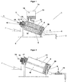
- FIG. 1 shown hydraulic system is generally designated by the reference numeral 1. It comprises a pressure cylinder 2 and a pressure from the cylinder 2 to a not shown in the figure Pumpkalotte leading not shown in the figure Disposables pressure line 3.
- a piston 4 is arranged along the major axis L of the impression cylinder 2 in Can be moved longitudinally.
- the printing cylinder 2 is held within the dialysis machine with schematically illustrated holding means 5 so that the axis L is inclined at an angle ⁇ of 20 ° to the horizontal.
- the impression cylinder 2 is round in cross-section and has shell walls 6, a bottom surface 7 raised by the inclination and a bottom surface 8 lowered by the inclination.
- the pressure line 3 is connected to the lowered floor 8.
- the piston 4 is sealingly against the inside of the casing walls 6 and separates within the pressure cylinder 2, a working chamber 9 of a compensation chamber 10, wherein the working chamber 9 is arranged on the lowered and the compensation chamber 10 on the raised side of the piston 4.
- a degassing bore 11 is provided approximately on the raised half of the impression cylinder 2.
- a compensation bore 12 is provided at the upper vertex of the shell walls 6 and further in the raised half of the impression cylinder 2.
- the connections on the expansion tank 13 are in the level above the holes 11 and 12.
- the surge tank 13 has an access 14 for filling the system with hydraulic fluid and an environmental opening 15.
- the environmental opening 15 connects the interior of the surge tank 13 with the ambient air and includes a 2-way exhaust valve.
- a spindle 16 and a stepping motor 17 are provided.
- the spindle 16 connects the piston 4 with the stepper motor 17 and pierces the raised bottom 7 of the printing cylinder 2 through a bore 18.
- the stepping motor 17 is designed to cause a rotation of the spindle 16.
- the spindle 16 has an external thread which cooperates with an internal thread in the bore 18 such that the rotational movement of the spindle 16 simultaneously causes a translational movement in the axis L.
- an encoder 19 is further provided, by means of which, in cooperation with a suitable contact on the spindle 16, the position of the Spindle 16 can be determined.
- the stepping motor 17 and the encoder 19 are connected to a control unit, not shown in detail in the figure, that the signal of the encoder 19 for controlling the stepping motor 17 is used.
- a pressure sensor 20 is arranged, which measures the hydraulic pressure and may also be connected to the control unit of the device.
- the pressure sensor may also be arranged at another suitable location.
- the illustrated hydraulic system may be part of a peritoneal dialysis machine, with the aforementioned pumping dome acting on a disposable for the dialysis fluid to flow in and out.
- FIG. 2 shown hydraulic system differs from that according to FIG. 1 in that both the expansion tank 13 and the compensation hole 12 are missing.
- the degassing hole 11 is connected to the ambient air.
- a suction device not shown in detail in the form of, for example, a syringe.
- a corresponding access 14 is arranged on the pressure line 3.
- In the compensation chamber 10 is (compressible) air.
- This further simplified system makes use of a constant volume of liquid, which makes it possible to remove the surge tank 13.
- the system can be vented once via the vent hole 11 active (eg with a syringe).
- the access 14 is provided to fill the system.
- FIG. 3 shown hydraulic system differs from that according to FIG. 1 in that the compensation bore 12 is not connected to the surge tank 13 and that the expansion tank 13, the surrounding opening 15 is missing and the surge tank is instead connected to a motor-driven vacuum pump 21, which is designed to generate a negative pressure in the interior of the surge tank 13.
- a motor-driven vacuum pump 21 which is designed to generate a negative pressure in the interior of the surge tank 13.
- the structure according to the in FIG. 2 illustrated embodiment added a function to accelerate the degassing of the hydraulic fluid.
- a ventilation valve 22 is arranged between the vacuum pump 21 and the surge tank.
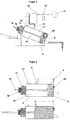
- FIG. 4 the operation of a hydraulic system according to the invention is explained, the all three systems just described according to FIGS. 1 to 3 is mean.
- the piston 4 is moved within the pressure cylinder along the axis L to push hydraulic fluid from the working chamber in the pressure line 3 and ultimately to the pumping dome.
- the working stroke of the piston 4 is indicated in the figure by the reference A and takes the portion of the printing cylinder 2 between the lowered bottom 9 and the degassing bottom 11 a.
- the degassing position for degassing the hydraulic fluid is identified by the reference symbol E. It corresponds to a position of the piston 4 on the raised side of the degassing bore 11 and between the degassing bore 11 and a possible compensation bore 12.
- the degassing bore 11 thus occupies the highest level of the actual working range of the hydraulic system.
Landscapes
- Engineering & Computer Science (AREA)
- Health & Medical Sciences (AREA)
- Heart & Thoracic Surgery (AREA)
- General Engineering & Computer Science (AREA)
- Mechanical Engineering (AREA)
- Urology & Nephrology (AREA)
- Emergency Medicine (AREA)
- Biomedical Technology (AREA)
- Physics & Mathematics (AREA)
- Vascular Medicine (AREA)
- Anesthesiology (AREA)
- Fluid Mechanics (AREA)
- Hematology (AREA)
- Life Sciences & Earth Sciences (AREA)
- Animal Behavior & Ethology (AREA)
- General Health & Medical Sciences (AREA)
- Public Health (AREA)
- Veterinary Medicine (AREA)
- External Artificial Organs (AREA)
Abstract
Description
- Die Erfindung betrifft ein Dialysegerät mit einem Aktor und einem Hydrauliksystem zur Betätigung des Aktors.
- In Dialysegeräten und beispielsweise in Peritonealdialysegeräten kommen oftmals hydraulische Aktorsysteme wie beispielsweise hydraulisch betriebene Pumpen zum Einsatz. Diese können beispielsweise dazu dienen, eine Dialyseflüssigkeit in einem Disposable zu fördern. Um die Gasfreiheit derartiger hydraulischer Systeme zu gewährleisten und um eine exakte Steuerung der Pumpe und somit Bilanzierung des Dialysefluids zu erreichen, ist im Stand der Technik bisweilen eine aufwändige konstruktive Gestaltung des hydraulischen Systems erforderlich, insbesondere dann, wenn eine Entgasung über das Disposable nicht erforderlich sein soll (was dann in vorteilhafter Weise zu konstruktiv einfacheren Disposables führt).
- Aufgabe der Erfindung ist es, ein Dialysegerät mit einem einfach konstruierten gattungsgemäßen Hydrauliksystem bereitzustellen, bei dem eine Entgasung über das Disposable entbehrlich ist.
- Vor diesem Hintergrund betrifft die Erfindung ein Dialysegerät mit einem Aktor und einem Hydrauliksystem zur Betätigung des Aktors, wobei das Hydrauliksystem einen Druckzylinder und eine vom Druckzylinder zum Aktor führende Druckleitung aufweist und wobei der Druckzylinder einen Kolben aufweist, der in der Hauptachse des Druckzylinders verschoben werden kann, wobei der Druckzylinder so im Dialysegerät angeordnet ist, dass die Hauptachse in einem Neigungswinkel zur Horizontalen steht, wobei die Druckleitung im abgesenkten Endbereich des Druckzylinders angeschlossen ist und wobei eine Entgasungsöffnung vorgesehen ist, die in einem nach oben zeigenden Mantelsegment des Druckzylinders angeordnet ist.
- Der Kolben liegt dichtend an den Innenwänden des Druckzylinders an und trennt innerhalb des Druckzylinders eine Arbeits- von einer Ausgleichskammer. Die Arbeitskammer ist auf der abgesenkten und die Ausgleichskammer auf der angehobenen Seite des Kolbens angeordnet.
- Der Druckzylinder weist eine Mantelfläche und zwei Bodenflächen auf, wobei die Positionsangaben "abgesenkt" und "angehoben" aus der Neigung der Hauptachse resultieren. Als die abgesenkte Bodenfläche ist die aufgrund der Neigung auf einem tieferen Niveau liegende Bodenfläche zu verstehen, und als die angehobene Bodenfläche die aufgrund der Neigung auf einem höheren Niveau liegende Bodenfläche. Die Begriffe des "abgesenkten" bzw. "angehobenen" Endbereichs bezeichnen den Bereich an oder nahe der jeweiligen Bodenfläche. Die Positionsangaben "oben", "unten" und "seitlich" bezeichnen über den Umfang des Mantels verteilte Positionen ohne Berücksichtigung der Neigung der Hauptachse.
- In einer Ausführungsform hat der Druckzylinder einen runden Querschnitt.
- In einer Ausführungsform ist die Druckleitung an der abgesenkten Bodenfläche des Druckzylinders angeschlossen.
- In einer Ausführungsform ist die Entgasungsöffnung an einem oberen Scheitelpunkt des Zylindermantels und/oder in der angehobenen Hälfte oder im angehobenen Drittel des Druckzylinders angeordnet.
- In einer Ausführungsform beträgt der Neigungswinkel der Hauptachse 5-45°, vorzugsweise 10-30° und weiter vorzugsweise 15-25°.
- In einer Ausführungsform ist in einem angehobenen Mantelsegment des Druckzylinders zusätzlich zur Entgasungsöffnung eine Ausgleichsöffnung angeordnet, wobei die Ausgleichsöffnung vorzugsweise näher am angehobenen Boden des Druckzylinders liegt als die Entgasungsöffnung.
- In einer Ausführungsform stehen die Entgasungs- und/oder die Ausgleichsöffnung mit einem Ausgleichsbehälter in Verbindung. Die Verbindung zwischen der Entgasungs- und/oder die Ausgleichsöffnung und dem Ausgleichsbehälter kann anhand einer Leitung erfolgen. In der Verbindung zwischen Entgasungs- und/oder die Ausgleichsöffnung und Ausgleichsbehälter sind vorzugsweise keine Ventile angeordnet.
- Der Ausgleichsbehälter kann als Reservoir für die Hydraulikflüssigkeit dienen, die in der Arbeitskammer und gegebenenfalls auch in der Ausgleichskammer vorliegt. Entsprechend kann der Ausgleichsbehälter einen Zugang für dessen Befüllen mit Hydraulikflüssigkeit aufweisen. Der Fluss von Hydraulikflüssigkeit zwischen dem Druckzylinder und dem Ausgleichsbehälter kann durch die Entgasungs- und/oder die Ausgleichsöffnung erfolgen. In einer Ausführungsform weist der Ausgleichsbehälter eine Umgebungsöffnung auf, die den Innenraum des Ausgleichsbehälters mit der Umgebungsluft verbindet. An der Umgebungsöffnung bzw. in einer von der Umgebungsöffnung abführenden Leitung kann ein Ventil angeordnet sein.
- In einer Ausführungsform weist die Druckleitung oder der abgesenkte Endbereich des Druckzylinders einen Zugang zu deren Befüllung mit Hydraulikflüssigkeit auf. Sofern kein Ausgleichsbehälter vorhanden ist, kann das System anhand eines derartigen Zugangs mit Hydraulikflüssigkeit befüllt werden.
- In einer Ausführungsform ist eine Saugvorrichtung vorgesehen, die mit der Entgasungsöffnung oder dem Innenraum des Ausgleichsbehälters verbunden und ausgebildet ist, an der Entgasungsöffnung oder im Innenraum des Ausgleichsbehälters einen Unterdruck zu erzeugen. Mit einer derartigen Saugvorrichtung kann der Entgasungsvorgang der Hydraulikflüssigkeit unterstützt werden. Geeignete Saugvorrichtungen umfassen einfache mechanische Vorrichtungen wie beispielsweise eine Spritze, die vorzugsweise an der Entgasungsöffnung ansetzt. Weitere geeignete Saugvorrichtungen umfassen beispielsweise eine motorbetriebene Vakuumpumpe, die vorzugsweise mit dem Innenraum des Ausgleichsbehälters in Verbindung steht.
- In einer Ausführungsform ist das Dialysegerät so ausgebildet, dass der Kolben anhand eines Schrittmotors und einer Spindel bewegt wird. Bei dem Schrittmotor handelt es sich vorzugsweise um einen Synchronmotor, der die Spindel durch ein gesteuertes, schrittweise rotierendes, elektromagnetisches Feld von Statorspulen um einen definierten Winkel (Schritt) oder ein Vielfaches davon drehen kann. Die Spindel kann ein Außengewinde aufweisen, um anhand der vom Schrittmotor erzeugten Drehbewegung eine translatorische Bewegung in der Achse des Druckzylinders zu erzeugen. Sie durchläuft vorzugsweise eine Bohrung am angehobenen Boden des Druckzylinders, die ein Innengewinde aufweisen kann.
- In einer Ausführungsform ist ein vozugsweise rotatorischer Kodierer vorgesehen, um die Position der Spindel zu bestimmen. Geeignete Beispiele umfassen optische, magnetische und mechanische Kodierer mit entsprechenden Kontakten an der Spindel.
- Der Schrittmotor und/oder der Kodierer sind vorzugsweise an der Außenseite des angehobenen Bodens des Druckzylinders angeordnet. Der Schrittmotor und der Kodierer stehen vorzugsweise mit der Steuereinheit des Geräts in Verbindung. So kann beispielsweise das Signal des Kodierers genützt werden, um den Schrittmotor zu steuern.
- Durch einen derartigen Antrieb des Kolbens kann gegenüber einer alternativen Motorsteuerung eine exaktere Fluiddosierung erreicht werden und Sensoren wie beispielsweise Längensensoren für eine Pumpe entfallen.
- In einer Ausführungsform ist am Druckzylinder oder an der Druckleitung ein Drucksensor angeordnet. Beispielsweise kann der Drucksensor im abgesenkten Endbereich bzw. am abgesenkten Boden des Druckzylinders angeordnet sein.
- In einer Ausführungsform handelt es sich bei dem Dialysegerät um ein Peritonealdialysegerät.
- In einer Ausführungsform handelt es sich bei dem Aktor um eine vorzugsweise disposableseitig angeordnete Pumpe, wobei die Druckleitung mit einer Pumpkalotte in Verbindung steht.
- Weitere Einzelheiten und Vorteile der Erfindung ergeben sich aus den nachfolgend anhand der Figuren beschriebenen Ausführungsbeispielen. In den Figuren zeigen:
- Figur 1:
- ein Hydrauliksystem eines Dialysegeräts gemäß einer ersten Ausführungsform der Erfindung;
- Figur 2:
- ein Hydrauliksystem eines Dialysegeräts gemäß einer zweiten Ausführungsform der Erfindung,
- Figur 3:
- ein Hydrauliksystem eines Dialysegeräts gemäß einer dritten Ausführungsform der Erfindung, und
- Figur 4:
- eine Darstellung zur Funktionsweise derartiger Hydrauliksysteme.
- Das in
Figur 1 dargestellte Hydrauliksystem ist generell mit dem Bezugszeichen 1 gekennzeichnet. Es umfasst einen Druckzylinder 2 und eine vom Druckzylinder 2 zur einer in der Figur nicht näher dargestellten Pumpkalotte eines in der Figur nicht näher dargestellten Disposables führende Druckleitung 3. Innerhalb des Druckzylinders 2 ist ein Kolben 4 angeordnet, der entlang der Hauptachse L des Druckzylinders 2 in Längsrichtung verschoben werden kann. Der Druckzylinder 2 ist innerhalb des Dialysegeräts mit schematisch dargestellten Haltemitteln 5 so gehalten, dass die Achse L in einem Winkel α von 20° zur Horizontalen geneigt ist. Der Druckzylinder 2 ist im Querschnitt rund und weist Mantelwände 6, eine durch die Neigung angehobene Bodenfläche 7 und eine durch die Neigung abgesenkte Bodenfläche 8 auf. Die Druckleitung 3 ist am abgesenkten Boden 8 angeschlossen. Der Kolben 4 liegt dichtend an der Innenseite der Mantelwände 6 an und trennt innerhalb des Druckzylinders 2 eine Arbeitskammer 9 von einer Ausgleichskammer 10, wobei die Arbeitskammer 9 auf der abgesenkten und die Ausgleichskammer 10 auf der angehobenen Seite des Kolbens 4 angeordnet ist. - Am oberen Scheitelpunkt der Mantelwände 6 ist etwa auf der angehobenen Hälfte des Druckzylinders 2 eine Entgasungsbohrung 11 vorgesehen. Zusätzlich ist am oberen Scheitelpunkt der Mantelwände 6 und weiter in der angehobenen Hälfte des Druckzylinders 2 eine Ausgleichsbohrung 12 vorgesehen. An beiden diesen Bohrungen sind Leitungen angeschlossen, die zu einem Ausgleichsbehälter 13 führen. Die Anschlüsse am Ausgleichsbehälter 13 stehen im Niveau über den Bohrungen 11 und 12. Der Ausgleichsbehälter 13 weist einen Zugang 14 zur Befüllung des Systems mit Hydraulikflüssigkeit sowie eine Umgebungsöffnung 15 auf. Die Umgebungsöffnung 15 verbindet den Innenraum des Ausgleichsbehälters 13 mit der Umgebungsluft und umfasst ein 2-Wege-Auslassventil.
- Da die Entgasungsbohrung 11 im normalen Pumpbetrieb (Erklärung siehe
Figur 4 ) mit der gegenüber der Arbeitskammer 9 angehobenen Ausgleichskammer 10 verbunden ist, entleert sich der Ausgleichbehälter 13 in die Ausgleichskammer 10. Das Design macht es daher nötig, die Ausgleichsbohrung 12 einzufügen, um im Entgasungszyklus (Erklärung sieheFigur 4 ) das Flüssigkeitsvolumen in der Ausgleichskammer 10 während der Bewegung des Kolbens 4 in den Ausgleichbehälter 13 zu verdrängen. - Zur Steuerung der Verschiebung des Kolbens 4 entlang der Achse L sind eine Spindel 16 und ein Schrittmotor 17 vorgesehen. Die Spindel 16 verbindet den Kolben 4 mit dem Schrittmotor 17 und durchstößt den angehobenen Boden 7 des Druckzylinders 2 dabei durch eine Bohrung 18. Der Schrittmotor 17 ist ausgebildet, um eine Rotation der Spindel 16 zu bewirken. Die Spindel 16 weist ein Außengewinde auf, das mit einem Innengewinde in der Bohrung 18 derart zusammenwirkt, dass die Drehbewegung der Spindel 16 gleichzeitig eine translatorische Bewegung in der Achse L bewirkt. Direkt an Spindel 16 und am Motor 17 ist ferner ein Kodierer 19 vorgesehen, anhand dessen unter Zusammenwirken mit einem geeigneten Kontakt an der Spindel 16 die Position der Spindel 16 bestimmt werden kann. Der Schrittmotor 17 und der Kodierer 19 sind so mit einer in der Figur nicht näher dargestellten Steuereinheit verbunden, dass das Signal des Kodierers 19 zur Steuerung des Schrittmotors 17 genützt wird. Am abgesenkten Boden 8 des Druckzylinders 2 ist ein Drucksensor 20 angeordnet, der den Hydraulikdruck misst und ebenfalls mit der Steuereinheit des Geräts verbunden sein kann.
- Der Drucksensor kann auch an einer anderen geeigneten Stelle angeordnet sein.
- Das in der
Figur 1 dargestellte Hydrauliksystem kann beispielsweise einen Teil eines Peritonealdialysegeräts darstellen, wobei die oben erwähnte Pumpkalotte an einem Disposable für den Ein- und Ablauf von Dialyseflüssigkeit wirkt. - Das in der
Figur 2 dargestellte Hydrauliksystem unterscheidet sich von demjenigen gemäßFigur 1 dadurch, dass sowohl der Ausgleichsbehälter 13 als auch die Ausgleichsbohrung 12 fehlen. Die Entgasungsbohrung 11 ist mit der Umgebungsluft verbunden. Zur Verbesserung der Entgasung der Hydraulikflüssigkeit kann an der Entgasungsbohrung 11 eine in der Figur nicht näher dargestellte Saugvorrichtung in Form beispielsweise einer Spritze angelegt sein. Um das System trotz des fehlenden Ausgleichsbehälters 13 mit Hydraulikflüssigkeit befüllen zu können, ist an der Druckleitung 3 ein entsprechender Zugang 14 angeordnet. In der Ausgleichskammer 10 befindet sich (kompressible) Luft. - Dieses weiter vereinfachte System macht sich ein konstantes Flüssigkeitsvolumen zu Nutze, was es ermöglicht, den Ausgleichbehälter 13 zu entfernen. Das System kann einmalig über die Entgasungsbohrung 11 aktiv (z.B. mit einer Spritze) entlüftet werden. Der Zugang 14 ist vorgesehen, um das System zu befüllen.
- Das in der
Figur 3 dargestellte Hydrauliksystem unterscheidet sich von demjenigen gemäßFigur 1 dadurch, dass die Ausgleichsbohrung 12 nicht mit dem Ausgleichsbehälter 13 verbunden ist und dass am Ausgleichsbehälter 13 die Umgebungsöffnung 15 fehlt und der Ausgleichsbehälter stattdessen an eine motorbetriebene Vakuumpumpe 21 angeschlossen ist, die ausgebildet ist, im Innenraum des Ausgleichsbehälters 13 einen Unterdruck zu erzeugen. So kann der Entgasungsvorgang der Hydraulikflüssigkeit unterstützt werden. So wurde dem Aufbau gemäß der inFigur 2 dargestellten Ausführungsform eine Funktion hinzugefügt, um das Entgasen der Hydraulikflüssigkeit zu beschleunigen. Zwischen der Vakuumpumpe 21 und dem Ausgleichsbehälter ist ein Be- und Entlüftungsventil 22 angeordnet. - In
Figur 4 wird die Funktionsweise eines erfindungsgemäßen Hydrauliksystems erklärt, die allen drei eben beschriebenen Systemen gemäßFiguren 1 bis 3 gemein ist. So wird der Kolben 4 innerhalb des Druckzylinders entlang der Achse L bewegt, um Hydraulikflüssigkeit aus der Arbeitskammer in die Druckleitung 3 und letztlich zur Pumpkalotte zu drücken. Der Arbeitshub des Kolbens 4 ist in der Figur mit dem Bezugszeichen A gekennzeichnet und nimmt den Abschnitt des Druckzylinders 2 zwischen dem abgesenkten Boden 9 und der Entgasungsboden 11 ein. Die Entgasungsposition zum Entgasen der Hydraulikflüssigkeit ist mit dem Bezugszeichen E gekennzeichnet. Sie entspricht einer Position des Kolbens 4 auf der angehobenen Seite der Entgasungsbohrung 11 bzw. zwischen der Entgasungsbohrung 11 und einer etwaigen Ausgleichsbohrung 12. Die Entgasungsbohrung 11 nimmt also das höchste Niveau des eigentlichen Arbeitsbereichs des Hydrauliksystems ein.
Claims (10)
- Dialysegerät mit einem Aktor und einem Hydrauliksystem (1) zur Betätigung des Aktors, wobei das Hydrauliksystem (1) einen Druckzylinder (2) und eine vom Druckzylinder (2) zum Aktor führende Druckleitung (3) aufweist und wobei der Druckzylinder (2) einen Kolben (4) aufweist, der in der Hauptachse (L) des Druckzylinders (2) verschoben werden kann,
dadurch gekennzeichnet,
dass der Druckzylinder (2) so im Dialysegerät angeordnet ist, dass die Hauptachse (L) in einem Neigungswinkel (α) zur Horizontalen steht, wobei die Druckleitung (3) im abgesenkten Endbereich des Druckzylinders (2) angeschlossen ist und wobei eine Entgasungsöffnung (11) vorgesehen ist, die in einem nach oben zeigenden Mantelsegment des Druckzylinders (2) angeordnet ist. - Dialysegerät nach Anspruch 1, dadurch gekennzeichnet, dass die Entgasungsöffnung an einem oberen Scheitelpunkt des Zylindermantels und/oder in der angehobenen Hälfte oder im angehobenen Drittel des Druckzylinders (2) angeordnet ist.
- Dialysegerät nach einem der vorhergehenden Ansprüche, dadurch gekennzeichnet, dass der Neigungswinkel (α) der Hauptachse 5-45°, vorzugsweise 10-30° und weiter vorzugsweise 15-25° beträgt.
- Dialysegerät nach einem der vorhergehenden Ansprüche, dadurch gekennzeichnet, dass in einem angehobenen Mantelsegment des Druckzylinders (2) zusätzlich zur Entgasungsöffnung (11) eine Ausgleichsöffnung (12) angeordnet ist, wobei die Ausgleichsöffnung (12) vorzugsweise näher am angehobenen Boden (7) des Druckzylinders (2) liegt als die Entgasungsöffnung (11).
- Dialysegerät nach einem der vorhergehenden Ansprüche, dadurch gekennzeichnet, dass die Entgasungsöffnung (11) und/oder die Ausgleichsöffnung (12) mit einem Ausgleichsbehälter (13) in Verbindung stehen.
- Dialysegerät nach Anspruch 5, dadurch gekennzeichnet, dass der Ausgleichsbehälter (13) eine Umgebungsöffnung (14) aufweist, die den Innen-raum des Ausgleichsbehälters (13) mit der Umgebungsluft verbindet.
- Dialysegerät nach einem der vorhergehenden Ansprüche, dadurch gekennzeichnet, dass die Druckleitung (3) oder der abgesenkte Endbereich des Druckzylinders (2) einen Zugang (14) zu deren Befüllung mit Hydraulikflüssigkeit aufweist.
- Dialysegerät nach einem der vorhergehenden Ansprüche, dadurch gekennzeichnet, dass eine Saugvorrichtung (21) vorgesehen ist, die mit der Entgasungsöffnung (11) oder dem Innenraum des Ausgleichsbehälters (13) verbunden und ausgebildet ist, an der Entgasungsöffnung (11) oder im Innen-raum des Ausgleichsbehälters (13) einen Unterdruck zu erzeugen.
- Dialysegerät nach einem der vorhergehenden Ansprüche, dadurch gekennzeichnet, dass der Kolben (4) anhand eines Schrittmotors (17) und einer Spindel (16) bewegt wird.
- Dialysegerät nach Anspruch 9, dadurch gekennzeichnet, dass ein vozugsweise rotatorischer Kodierer (19) vorgesehen ist, um die Position der Spindel (16) zu bestimmen.
Priority Applications (2)
| Application Number | Priority Date | Filing Date | Title |
|---|---|---|---|
| EP16169544.0A EP3243536B1 (de) | 2016-05-13 | 2016-05-13 | Dialysegerät mit einem aktor und einem hydrauliksystem |
| CN201710329512.6A CN107366644B (zh) | 2016-05-13 | 2017-05-11 | 具有致动器和液压系统的透析机 |
Applications Claiming Priority (1)
| Application Number | Priority Date | Filing Date | Title |
|---|---|---|---|
| EP16169544.0A EP3243536B1 (de) | 2016-05-13 | 2016-05-13 | Dialysegerät mit einem aktor und einem hydrauliksystem |
Publications (2)
| Publication Number | Publication Date |
|---|---|
| EP3243536A1 true EP3243536A1 (de) | 2017-11-15 |
| EP3243536B1 EP3243536B1 (de) | 2022-06-29 |
Family
ID=55970889
Family Applications (1)
| Application Number | Title | Priority Date | Filing Date |
|---|---|---|---|
| EP16169544.0A Active EP3243536B1 (de) | 2016-05-13 | 2016-05-13 | Dialysegerät mit einem aktor und einem hydrauliksystem |
Country Status (2)
| Country | Link |
|---|---|
| EP (1) | EP3243536B1 (de) |
| CN (1) | CN107366644B (de) |
Cited By (1)
| Publication number | Priority date | Publication date | Assignee | Title |
|---|---|---|---|---|
| US10195418B2 (en) | 2014-10-10 | 2019-02-05 | Nxstage Medical, Inc. | Pinch clamp devices, methods, and systems |
Citations (4)
| Publication number | Priority date | Publication date | Assignee | Title |
|---|---|---|---|---|
| DE1053316B (de) * | 1957-05-23 | 1959-03-19 | Sigma Lutin | Entlueftungsvorrichtung fuer hydraulisch durch Plunger betaetigte Membranpumpen |
| US3291055A (en) * | 1965-08-02 | 1966-12-13 | Alexander S Limpert | Self-purging proportioning pump for corrosive liquids |
| DE102010005746A1 (de) * | 2010-01-26 | 2011-07-28 | Fresenius Medical Care Deutschland GmbH, 61352 | Medizintechnisches Gerät |
| DE102014010108A1 (de) * | 2014-07-08 | 2016-01-14 | Lewa Gmbh | Hydraulisch angetriebene Membranpumpe |
Family Cites Families (6)
| Publication number | Priority date | Publication date | Assignee | Title |
|---|---|---|---|---|
| CN100548392C (zh) * | 2004-08-24 | 2009-10-14 | 日机装株式会社 | 血液净化装置 |
| DE102010005745A1 (de) * | 2010-01-26 | 2011-07-28 | Fresenius Medical Care Deutschland GmbH, 61352 | Dialysemaschine |
| CN104117104A (zh) * | 2014-07-23 | 2014-10-29 | 古英明 | 一体式带血液灌流及血液透析结构的血液净化装置 |
| CN203989201U (zh) * | 2014-08-15 | 2014-12-10 | 中国人民解放军第三军医大学第二附属医院 | 一种基于Diapact CRRT机并用于双重滤过血浆置换的改良装置 |
| CN105477711A (zh) * | 2015-08-11 | 2016-04-13 | 常州华岳微创医疗器械有限公司 | 一种用于血液净化装置的排气装置 |
| CN105363085B (zh) * | 2015-12-10 | 2018-05-22 | 威海威高血液净化制品有限公司 | 血液净化装置 |
-
2016
- 2016-05-13 EP EP16169544.0A patent/EP3243536B1/de active Active
-
2017
- 2017-05-11 CN CN201710329512.6A patent/CN107366644B/zh active Active
Patent Citations (4)
| Publication number | Priority date | Publication date | Assignee | Title |
|---|---|---|---|---|
| DE1053316B (de) * | 1957-05-23 | 1959-03-19 | Sigma Lutin | Entlueftungsvorrichtung fuer hydraulisch durch Plunger betaetigte Membranpumpen |
| US3291055A (en) * | 1965-08-02 | 1966-12-13 | Alexander S Limpert | Self-purging proportioning pump for corrosive liquids |
| DE102010005746A1 (de) * | 2010-01-26 | 2011-07-28 | Fresenius Medical Care Deutschland GmbH, 61352 | Medizintechnisches Gerät |
| DE102014010108A1 (de) * | 2014-07-08 | 2016-01-14 | Lewa Gmbh | Hydraulisch angetriebene Membranpumpe |
Cited By (3)
| Publication number | Priority date | Publication date | Assignee | Title |
|---|---|---|---|---|
| US10195418B2 (en) | 2014-10-10 | 2019-02-05 | Nxstage Medical, Inc. | Pinch clamp devices, methods, and systems |
| US11213669B2 (en) | 2014-10-10 | 2022-01-04 | Nxstage Medical, Inc. | Pinch clamp devices, methods, and systems |
| US12005224B2 (en) | 2014-10-10 | 2024-06-11 | Nxstage Medical, Inc. | Pinch clamp devices, methods, and systems |
Also Published As
| Publication number | Publication date |
|---|---|
| EP3243536B1 (de) | 2022-06-29 |
| CN107366644A (zh) | 2017-11-21 |
| CN107366644B (zh) | 2021-04-02 |
Similar Documents
| Publication | Publication Date | Title |
|---|---|---|
| EP2039582B1 (de) | Aktiver hydraulischer Dämpfer und hydraulischer Stellantrieb | |
| EP2678570B1 (de) | Hydraulische einrichtung zur betätigung einer kupplung | |
| EP1606039B1 (de) | Mehrfunktionsfilter | |
| EP2212166B1 (de) | Hydraulikaggregat für schlupfgeregelte bremsanlagen | |
| EP0873475A1 (de) | Verlustarmer antrieb für mehrere hydraulische aktuatoren | |
| DE102010053811A1 (de) | Störungssicheres Betätigungssystem | |
| EP0271744A2 (de) | Elektrohydrostatischer Aktuator | |
| DE202015106161U1 (de) | Elektrohydraulische Antriebseinheit | |
| DE3708327A1 (de) | Einrichtung zum foerdern von fluessigkeit auf zwei ueber spritzduesen zu netzende, mit abstand voneinander angeordnete scheibenbereiche eines kraftfahrzeugs | |
| DE19600650A1 (de) | Antrieb für einen hydraulischen doppelwirkenden Aktuator | |
| EP3243536B1 (de) | Dialysegerät mit einem aktor und einem hydrauliksystem | |
| WO2023208795A1 (de) | Leckagediagnoseverfahren und leckagediagnosesystem für einen tank eines fahrzeugs | |
| WO2023208796A1 (de) | Leckagediagnoseverfahren und leckagediagnosesystem für einen tank eines fahrzeugs | |
| WO2016083063A1 (de) | Lenksystem für ein kraftfahrzeug und verfahren zum entlüften eines lenksystems für ein kraftfahrzeug | |
| DE102021208930B4 (de) | Verteilungseinrichtung und Flüssigkeitsverteilungsaktuator | |
| EP1071960A1 (de) | Dosiervorrichtung sowie verfahren zum betreiben einer dosiervorrichtung | |
| EP2738032B1 (de) | Tanksystem für ein Kraftfahrzeug | |
| DE19716081C1 (de) | Antrieb für einen hydraulischen Differentialzylinder | |
| WO2015000454A2 (de) | Befülladapter | |
| WO2019219491A1 (de) | Ventil | |
| DE102017219959A1 (de) | Elektrohydraulischer Aktuator | |
| DE10340506A1 (de) | Ventilanordnung und Hydraulikantrieb | |
| DE3400945A1 (de) | Zentralverriegelungsanlage eines kraftfahrzeugs | |
| DE102013214540A1 (de) | Federbein für ein Fahrzeugrad sowie Verfahren zu dessen Steuerung | |
| EP4074984A1 (de) | Hydraulikblock und verfahren |
Legal Events
| Date | Code | Title | Description |
|---|---|---|---|
| PUAI | Public reference made under article 153(3) epc to a published international application that has entered the european phase |
Free format text: ORIGINAL CODE: 0009012 |
|
| STAA | Information on the status of an ep patent application or granted ep patent |
Free format text: STATUS: REQUEST FOR EXAMINATION WAS MADE |
|
| 17P | Request for examination filed |
Effective date: 20160513 |
|
| AK | Designated contracting states |
Kind code of ref document: A1 Designated state(s): AL AT BE BG CH CY CZ DE DK EE ES FI FR GB GR HR HU IE IS IT LI LT LU LV MC MK MT NL NO PL PT RO RS SE SI SK SM TR |
|
| AX | Request for extension of the european patent |
Extension state: BA ME |
|
| STAA | Information on the status of an ep patent application or granted ep patent |
Free format text: STATUS: EXAMINATION IS IN PROGRESS |
|
| 17Q | First examination report despatched |
Effective date: 20180926 |
|
| GRAP | Despatch of communication of intention to grant a patent |
Free format text: ORIGINAL CODE: EPIDOSNIGR1 |
|
| STAA | Information on the status of an ep patent application or granted ep patent |
Free format text: STATUS: GRANT OF PATENT IS INTENDED |
|
| INTG | Intention to grant announced |
Effective date: 20220111 |
|
| GRAS | Grant fee paid |
Free format text: ORIGINAL CODE: EPIDOSNIGR3 |
|
| GRAA | (expected) grant |
Free format text: ORIGINAL CODE: 0009210 |
|
| STAA | Information on the status of an ep patent application or granted ep patent |
Free format text: STATUS: THE PATENT HAS BEEN GRANTED |
|
| AK | Designated contracting states |
Kind code of ref document: B1 Designated state(s): AL AT BE BG CH CY CZ DE DK EE ES FI FR GB GR HR HU IE IS IT LI LT LU LV MC MK MT NL NO PL PT RO RS SE SI SK SM TR |
|
| REG | Reference to a national code |
Ref country code: GB Ref legal event code: FG4D Free format text: NOT ENGLISH |
|
| REG | Reference to a national code |
Ref country code: CH Ref legal event code: EP |
|
| REG | Reference to a national code |
Ref country code: AT Ref legal event code: REF Ref document number: 1500857 Country of ref document: AT Kind code of ref document: T Effective date: 20220715 |
|
| REG | Reference to a national code |
Ref country code: IE Ref legal event code: FG4D Free format text: LANGUAGE OF EP DOCUMENT: GERMAN |
|
| REG | Reference to a national code |
Ref country code: DE Ref legal event code: R096 Ref document number: 502016015007 Country of ref document: DE |
|
| REG | Reference to a national code |
Ref country code: LT Ref legal event code: MG9D |
|
| PG25 | Lapsed in a contracting state [announced via postgrant information from national office to epo] |
Ref country code: FI Free format text: LAPSE BECAUSE OF FAILURE TO SUBMIT A TRANSLATION OF THE DESCRIPTION OR TO PAY THE FEE WITHIN THE PRESCRIBED TIME-LIMIT Effective date: 20220629 Ref country code: BG Free format text: LAPSE BECAUSE OF FAILURE TO SUBMIT A TRANSLATION OF THE DESCRIPTION OR TO PAY THE FEE WITHIN THE PRESCRIBED TIME-LIMIT Effective date: 20220929 Ref country code: SE Free format text: LAPSE BECAUSE OF FAILURE TO SUBMIT A TRANSLATION OF THE DESCRIPTION OR TO PAY THE FEE WITHIN THE PRESCRIBED TIME-LIMIT Effective date: 20220629 Ref country code: NO Free format text: LAPSE BECAUSE OF FAILURE TO SUBMIT A TRANSLATION OF THE DESCRIPTION OR TO PAY THE FEE WITHIN THE PRESCRIBED TIME-LIMIT Effective date: 20220929 Ref country code: LT Free format text: LAPSE BECAUSE OF FAILURE TO SUBMIT A TRANSLATION OF THE DESCRIPTION OR TO PAY THE FEE WITHIN THE PRESCRIBED TIME-LIMIT Effective date: 20220629 Ref country code: HR Free format text: LAPSE BECAUSE OF FAILURE TO SUBMIT A TRANSLATION OF THE DESCRIPTION OR TO PAY THE FEE WITHIN THE PRESCRIBED TIME-LIMIT Effective date: 20220629 Ref country code: GR Free format text: LAPSE BECAUSE OF FAILURE TO SUBMIT A TRANSLATION OF THE DESCRIPTION OR TO PAY THE FEE WITHIN THE PRESCRIBED TIME-LIMIT Effective date: 20220930 |
|
| REG | Reference to a national code |
Ref country code: NL Ref legal event code: MP Effective date: 20220629 |
|
| PG25 | Lapsed in a contracting state [announced via postgrant information from national office to epo] |
Ref country code: RS Free format text: LAPSE BECAUSE OF FAILURE TO SUBMIT A TRANSLATION OF THE DESCRIPTION OR TO PAY THE FEE WITHIN THE PRESCRIBED TIME-LIMIT Effective date: 20220629 Ref country code: LV Free format text: LAPSE BECAUSE OF FAILURE TO SUBMIT A TRANSLATION OF THE DESCRIPTION OR TO PAY THE FEE WITHIN THE PRESCRIBED TIME-LIMIT Effective date: 20220629 |
|
| PG25 | Lapsed in a contracting state [announced via postgrant information from national office to epo] |
Ref country code: NL Free format text: LAPSE BECAUSE OF FAILURE TO SUBMIT A TRANSLATION OF THE DESCRIPTION OR TO PAY THE FEE WITHIN THE PRESCRIBED TIME-LIMIT Effective date: 20220629 |
|
| PG25 | Lapsed in a contracting state [announced via postgrant information from national office to epo] |
Ref country code: SM Free format text: LAPSE BECAUSE OF FAILURE TO SUBMIT A TRANSLATION OF THE DESCRIPTION OR TO PAY THE FEE WITHIN THE PRESCRIBED TIME-LIMIT Effective date: 20220629 Ref country code: SK Free format text: LAPSE BECAUSE OF FAILURE TO SUBMIT A TRANSLATION OF THE DESCRIPTION OR TO PAY THE FEE WITHIN THE PRESCRIBED TIME-LIMIT Effective date: 20220629 Ref country code: RO Free format text: LAPSE BECAUSE OF FAILURE TO SUBMIT A TRANSLATION OF THE DESCRIPTION OR TO PAY THE FEE WITHIN THE PRESCRIBED TIME-LIMIT Effective date: 20220629 Ref country code: PT Free format text: LAPSE BECAUSE OF FAILURE TO SUBMIT A TRANSLATION OF THE DESCRIPTION OR TO PAY THE FEE WITHIN THE PRESCRIBED TIME-LIMIT Effective date: 20221031 Ref country code: ES Free format text: LAPSE BECAUSE OF FAILURE TO SUBMIT A TRANSLATION OF THE DESCRIPTION OR TO PAY THE FEE WITHIN THE PRESCRIBED TIME-LIMIT Effective date: 20220629 Ref country code: EE Free format text: LAPSE BECAUSE OF FAILURE TO SUBMIT A TRANSLATION OF THE DESCRIPTION OR TO PAY THE FEE WITHIN THE PRESCRIBED TIME-LIMIT Effective date: 20220629 |
|
| PG25 | Lapsed in a contracting state [announced via postgrant information from national office to epo] |
Ref country code: PL Free format text: LAPSE BECAUSE OF FAILURE TO SUBMIT A TRANSLATION OF THE DESCRIPTION OR TO PAY THE FEE WITHIN THE PRESCRIBED TIME-LIMIT Effective date: 20220629 Ref country code: IS Free format text: LAPSE BECAUSE OF FAILURE TO SUBMIT A TRANSLATION OF THE DESCRIPTION OR TO PAY THE FEE WITHIN THE PRESCRIBED TIME-LIMIT Effective date: 20221029 |
|
| REG | Reference to a national code |
Ref country code: DE Ref legal event code: R097 Ref document number: 502016015007 Country of ref document: DE |
|
| PG25 | Lapsed in a contracting state [announced via postgrant information from national office to epo] |
Ref country code: AL Free format text: LAPSE BECAUSE OF FAILURE TO SUBMIT A TRANSLATION OF THE DESCRIPTION OR TO PAY THE FEE WITHIN THE PRESCRIBED TIME-LIMIT Effective date: 20220629 |
|
| PG25 | Lapsed in a contracting state [announced via postgrant information from national office to epo] |
Ref country code: DK Free format text: LAPSE BECAUSE OF FAILURE TO SUBMIT A TRANSLATION OF THE DESCRIPTION OR TO PAY THE FEE WITHIN THE PRESCRIBED TIME-LIMIT Effective date: 20220629 Ref country code: CZ Free format text: LAPSE BECAUSE OF FAILURE TO SUBMIT A TRANSLATION OF THE DESCRIPTION OR TO PAY THE FEE WITHIN THE PRESCRIBED TIME-LIMIT Effective date: 20220629 |
|
| PLBE | No opposition filed within time limit |
Free format text: ORIGINAL CODE: 0009261 |
|
| STAA | Information on the status of an ep patent application or granted ep patent |
Free format text: STATUS: NO OPPOSITION FILED WITHIN TIME LIMIT |
|
| 26N | No opposition filed |
Effective date: 20230330 |
|
| P01 | Opt-out of the competence of the unified patent court (upc) registered |
Effective date: 20230602 |
|
| PG25 | Lapsed in a contracting state [announced via postgrant information from national office to epo] |
Ref country code: SI Free format text: LAPSE BECAUSE OF FAILURE TO SUBMIT A TRANSLATION OF THE DESCRIPTION OR TO PAY THE FEE WITHIN THE PRESCRIBED TIME-LIMIT Effective date: 20220629 |
|
| REG | Reference to a national code |
Ref country code: CH Ref legal event code: PL |
|
| PG25 | Lapsed in a contracting state [announced via postgrant information from national office to epo] |
Ref country code: MC Free format text: LAPSE BECAUSE OF FAILURE TO SUBMIT A TRANSLATION OF THE DESCRIPTION OR TO PAY THE FEE WITHIN THE PRESCRIBED TIME-LIMIT Effective date: 20220629 |
|
| REG | Reference to a national code |
Ref country code: BE Ref legal event code: MM Effective date: 20230531 |
|
| PG25 | Lapsed in a contracting state [announced via postgrant information from national office to epo] |
Ref country code: MC Free format text: LAPSE BECAUSE OF FAILURE TO SUBMIT A TRANSLATION OF THE DESCRIPTION OR TO PAY THE FEE WITHIN THE PRESCRIBED TIME-LIMIT Effective date: 20220629 Ref country code: LU Free format text: LAPSE BECAUSE OF NON-PAYMENT OF DUE FEES Effective date: 20230513 Ref country code: LI Free format text: LAPSE BECAUSE OF NON-PAYMENT OF DUE FEES Effective date: 20230531 Ref country code: IT Free format text: LAPSE BECAUSE OF FAILURE TO SUBMIT A TRANSLATION OF THE DESCRIPTION OR TO PAY THE FEE WITHIN THE PRESCRIBED TIME-LIMIT Effective date: 20220629 Ref country code: CH Free format text: LAPSE BECAUSE OF NON-PAYMENT OF DUE FEES Effective date: 20230531 |
|
| REG | Reference to a national code |
Ref country code: IE Ref legal event code: MM4A |
|
| PG25 | Lapsed in a contracting state [announced via postgrant information from national office to epo] |
Ref country code: IE Free format text: LAPSE BECAUSE OF NON-PAYMENT OF DUE FEES Effective date: 20230513 |
|
| PG25 | Lapsed in a contracting state [announced via postgrant information from national office to epo] |
Ref country code: IE Free format text: LAPSE BECAUSE OF NON-PAYMENT OF DUE FEES Effective date: 20230513 |
|
| PG25 | Lapsed in a contracting state [announced via postgrant information from national office to epo] |
Ref country code: BE Free format text: LAPSE BECAUSE OF NON-PAYMENT OF DUE FEES Effective date: 20230531 |
|
| REG | Reference to a national code |
Ref country code: AT Ref legal event code: MM01 Ref document number: 1500857 Country of ref document: AT Kind code of ref document: T Effective date: 20230513 |
|
| PG25 | Lapsed in a contracting state [announced via postgrant information from national office to epo] |
Ref country code: AT Free format text: LAPSE BECAUSE OF NON-PAYMENT OF DUE FEES Effective date: 20230513 |
|
| PG25 | Lapsed in a contracting state [announced via postgrant information from national office to epo] |
Ref country code: AT Free format text: LAPSE BECAUSE OF NON-PAYMENT OF DUE FEES Effective date: 20230513 |
|
| PG25 | Lapsed in a contracting state [announced via postgrant information from national office to epo] |
Ref country code: BG Free format text: LAPSE BECAUSE OF FAILURE TO SUBMIT A TRANSLATION OF THE DESCRIPTION OR TO PAY THE FEE WITHIN THE PRESCRIBED TIME-LIMIT Effective date: 20220629 |
|
| PG25 | Lapsed in a contracting state [announced via postgrant information from national office to epo] |
Ref country code: BG Free format text: LAPSE BECAUSE OF FAILURE TO SUBMIT A TRANSLATION OF THE DESCRIPTION OR TO PAY THE FEE WITHIN THE PRESCRIBED TIME-LIMIT Effective date: 20220629 |
|
| PG25 | Lapsed in a contracting state [announced via postgrant information from national office to epo] |
Ref country code: CY Free format text: LAPSE BECAUSE OF FAILURE TO SUBMIT A TRANSLATION OF THE DESCRIPTION OR TO PAY THE FEE WITHIN THE PRESCRIBED TIME-LIMIT; INVALID AB INITIO Effective date: 20160513 |
|
| PG25 | Lapsed in a contracting state [announced via postgrant information from national office to epo] |
Ref country code: HU Free format text: LAPSE BECAUSE OF FAILURE TO SUBMIT A TRANSLATION OF THE DESCRIPTION OR TO PAY THE FEE WITHIN THE PRESCRIBED TIME-LIMIT; INVALID AB INITIO Effective date: 20160513 |
|
| PG25 | Lapsed in a contracting state [announced via postgrant information from national office to epo] |
Ref country code: TR Free format text: LAPSE BECAUSE OF FAILURE TO SUBMIT A TRANSLATION OF THE DESCRIPTION OR TO PAY THE FEE WITHIN THE PRESCRIBED TIME-LIMIT Effective date: 20220629 |
|
| PGFP | Annual fee paid to national office [announced via postgrant information from national office to epo] |
Ref country code: GB Payment date: 20260421 Year of fee payment: 11 |
|
| PGFP | Annual fee paid to national office [announced via postgrant information from national office to epo] |
Ref country code: DE Payment date: 20260421 Year of fee payment: 11 |
|
| PGFP | Annual fee paid to national office [announced via postgrant information from national office to epo] |
Ref country code: FR Payment date: 20260421 Year of fee payment: 11 |