EP3243378A1 - Dispositif d'aspiration et support associé - Google Patents
Dispositif d'aspiration et support associé Download PDFInfo
- Publication number
- EP3243378A1 EP3243378A1 EP17169394.8A EP17169394A EP3243378A1 EP 3243378 A1 EP3243378 A1 EP 3243378A1 EP 17169394 A EP17169394 A EP 17169394A EP 3243378 A1 EP3243378 A1 EP 3243378A1
- Authority
- EP
- European Patent Office
- Prior art keywords
- suction device
- holding body
- saugnuckel
- wall element
- opening
- Prior art date
- Legal status (The legal status is an assumption and is not a legal conclusion. Google has not performed a legal analysis and makes no representation as to the accuracy of the status listed.)
- Granted
Links
- 230000035622 drinking Effects 0.000 claims abstract description 30
- 241001465754 Metazoa Species 0.000 claims abstract description 8
- 244000309466 calf Species 0.000 claims abstract description 8
- 241000283903 Ovis aries Species 0.000 claims abstract description 7
- 230000013011 mating Effects 0.000 claims abstract description 6
- 230000000384 rearing effect Effects 0.000 claims abstract description 4
- 239000004033 plastic Substances 0.000 claims description 8
- 229920003023 plastic Polymers 0.000 claims description 8
- 239000000463 material Substances 0.000 claims description 7
- 230000000845 anti-microbial effect Effects 0.000 claims description 6
- 229920006324 polyoxymethylene Polymers 0.000 claims description 5
- 229930182556 Polyacetal Natural products 0.000 claims description 4
- 229920002725 thermoplastic elastomer Polymers 0.000 claims description 3
- 210000002445 nipple Anatomy 0.000 abstract description 21
- 241000047428 Halter Species 0.000 description 6
- 235000021056 liquid food Nutrition 0.000 description 5
- 239000007788 liquid Substances 0.000 description 4
- 239000000654 additive Substances 0.000 description 3
- 230000000996 additive effect Effects 0.000 description 3
- 239000004599 antimicrobial Substances 0.000 description 3
- 238000005470 impregnation Methods 0.000 description 3
- 244000144972 livestock Species 0.000 description 3
- 238000000034 method Methods 0.000 description 3
- 239000010813 municipal solid waste Substances 0.000 description 3
- 241000124008 Mammalia Species 0.000 description 2
- 238000009825 accumulation Methods 0.000 description 2
- 230000015572 biosynthetic process Effects 0.000 description 2
- 238000010276 construction Methods 0.000 description 2
- 238000001035 drying Methods 0.000 description 2
- 238000003780 insertion Methods 0.000 description 2
- 230000037431 insertion Effects 0.000 description 2
- 238000004519 manufacturing process Methods 0.000 description 2
- 244000052769 pathogen Species 0.000 description 2
- 241000894006 Bacteria Species 0.000 description 1
- 235000019687 Lamb Nutrition 0.000 description 1
- 238000004140 cleaning Methods 0.000 description 1
- 239000011248 coating agent Substances 0.000 description 1
- 238000000576 coating method Methods 0.000 description 1
- 239000000356 contaminant Substances 0.000 description 1
- 238000011109 contamination Methods 0.000 description 1
- 230000001419 dependent effect Effects 0.000 description 1
- 235000013305 food Nutrition 0.000 description 1
- 230000035784 germination Effects 0.000 description 1
- 230000036541 health Effects 0.000 description 1
- 230000006872 improvement Effects 0.000 description 1
- 208000015181 infectious disease Diseases 0.000 description 1
- 239000004615 ingredient Substances 0.000 description 1
- 238000009434 installation Methods 0.000 description 1
- 230000003993 interaction Effects 0.000 description 1
- 230000007246 mechanism Effects 0.000 description 1
- 229910052751 metal Inorganic materials 0.000 description 1
- 239000002184 metal Substances 0.000 description 1
- 239000008267 milk Substances 0.000 description 1
- 210000004080 milk Anatomy 0.000 description 1
- 235000013336 milk Nutrition 0.000 description 1
- 238000005580 one pot reaction Methods 0.000 description 1
- 230000000149 penetrating effect Effects 0.000 description 1
- 230000035515 penetration Effects 0.000 description 1
- 230000008569 process Effects 0.000 description 1
- 230000035755 proliferation Effects 0.000 description 1
- 238000010992 reflux Methods 0.000 description 1
- 239000000523 sample Substances 0.000 description 1
- 238000007789 sealing Methods 0.000 description 1
- 229910052709 silver Inorganic materials 0.000 description 1
- 239000004332 silver Substances 0.000 description 1
- 238000002791 soaking Methods 0.000 description 1
- 238000004659 sterilization and disinfection Methods 0.000 description 1
- 239000000725 suspension Substances 0.000 description 1
Images


Classifications
-
- A—HUMAN NECESSITIES
- A01—AGRICULTURE; FORESTRY; ANIMAL HUSBANDRY; HUNTING; TRAPPING; FISHING
- A01K—ANIMAL HUSBANDRY; AVICULTURE; APICULTURE; PISCICULTURE; FISHING; REARING OR BREEDING ANIMALS, NOT OTHERWISE PROVIDED FOR; NEW BREEDS OF ANIMALS
- A01K9/00—Sucking apparatus for young stock ; Devices for mixing solid food with liquids
- A01K9/005—Teats or nipples
Definitions
- a cattle-drinking valve assembly for connection to a container which comprises a suction nipple with the aid of which liquid in the container can be sucked by the livestock.
- the cattle-drinking valve arrangement comprises a valve body, which can be fastened to the suction nipple and has a valve channel through which the liquid can flow, as well as a plug-in holder for attachment to the container.
- this document describes a method for the simple and rapid mounting of a cattle-drinking valve arrangement on a container.
- watering stations which have one or more suction devices on a flat fastening element, which are supplied with liquid food via a hose system.
- the suction devices can correspond to those for drinking buckets.
- a user of the suction device to perform the assembly or disassembly of the suction device in a simple manner, which in particular reduces the risk of contamination of the surfaces of the wall element, since no complex mounting steps must be performed.
- the corresponding locking mechanisms must be activated or released the risk that the interior of the watering device over contaminated areas on the arms or hands of the user will be further contaminated significantly lower. Due to the two-part construction, a disinfection of the suction device according to the invention is readily possible before or after an impregnation process.
- the groove on the holding body and the corresponding counter-element are arranged on the Saugnuckel.
- the contact surface is simultaneously provided as a sealing surface between the Saugnuckel and the interior of the wall element. Due to the bias in the axial direction by the insertion of the suction nipple between the contact surface and mating surface of the area of the annular surface is acted upon by a force oriented in the direction of the outer side of the wall member, which additionally supports the seal.
- the contact surface is flat on the side facing the inside of the wall element.
- the holding body may follow, so that a corresponding homogeneous suction device is formed via corresponding corresponding planar surfaces.
- the flap valve is mounted on a hook above an opening in the holding body.
- the suction nipple and the holding body in the region of the opening of the wall element has a substantially circular cross-section.
- the Saugnuckel is made of an elastic plastic material, in particular a thermoplastic elastomer.
- the holding body is made of a plastic material, in particular of polyacetal.
- the suction nipple and / or the holding body are provided with an antimicrobial coating.
- the antimicrobial function of the plastics used the proliferation and formation of pathogens, such as bacteria or the like can be contained. This results in an increase of the stable hygiene, which results in an improvement of the health of the animals and in a larger one economic benefits for the farmer.
- a corresponding additive can be added to the plastic material.
- an antimicrobial additive based on metal, for example based on silver, can be supplied.
- suction device on a stationary drinker, which may comprise one or more suction devices.
- the suction nipple has a first positioning aid and the holding body has a second positioning aid, so that the attachment of the suction nipple is fixed to the holding body.
- the postioning of Saugnuckels can be specified relative to the holding body by means of the corresponding first and second positioning, with an inwardly facing edge on Saugnuckel and a corresponding flattening on the holding body can be used to prevent rotation in the form of a Positionierschräge.
- the suction nipple has a first positioning aid and the holding body has a second positioning aid, so that the position of the suction nipple and of the holding body can be predetermined relative to a drinking bin.
- the positioning of the suction nipple and the holding body is predetermined, which can be formed in a simple manner by a radially outwardly facing raised element on Saugnuckel and holding body.
- a holder for a suction device described above which has a first opening, which is suitable for fastening the holder to a further device, and which has a second opening, so that the housing part enclosing the channel via first receiving surfaces and second receiving surfaces of the holding body protrudes through the second opening and comes to rest with respect to the outer surface in the receiving surfaces.
- the first breakthrough on the holder can be designed so that it can be inserted into a bottom ring of a Tränkeimers.
- a suction device according to the invention SV is shown in a perspective oblique view.
- the suction device SV comprises a Saugnuckel SN and a holding body HK, which is guided together with the Saugnuckel SN.
- a channel KA which opens at one end of the elongated Saugnuckel SN in an incision EI, which forms the suction opening for an animal, such as a calf or lamb.
- the incision EI may be formed in other embodiments in the form of a hole, for example, with 2 mm, 4 mm or 6 mm in diameter. Other variants are also conceivable.
- the Saugnuckel SN is made of a resilient plastic material, such as a thermoplastic elastomer.
- the holding body HK is also made of a plastic material, for example polyacetal. Both the suction nipple SN and the holding body HK can be mixed with an antimicrobial additive.
- Both the contact surface AF and the counter surface GF are formed with respect to a longitudinal axis LA as radial projections.
- the opening on a wall element is arranged according to the invention between the contact surface AF and the counter surface GF.
- Fig. 2A the Saugnuckel SN is shown again in a perspective view.
- the counter surface GF is designed in the radial direction with respect to the longitudinal axis LA with a lower height than the contact surface AF. Accordingly, it is possible to grip the Saugnuckel SN at its end facing the incision EI and to pull through an opening of a wall element, that the opening of the wall element between the contact surface AF and the counter surface GF comes to rest.
- the counter surface GF is formed, for example, with a slightly rounded cross section, so that the counter surface GF can be easily guided through an opening.
- FIG. 2B Suction cup SN is shown from an opposite side, allowing entry into a cavity HR inside the suction nipple SN becomes clear. In this cavity HR, the holding body HK is introduced for attachment of the suction device SV.
- Fig. 3 the Saugnuckel SN is shown again in a sectional view.
- the cut follows approximately a center line along the longitudinal axis LA.
- an inwardly directed groove NU is formed in the interior of the cavity HR.
- the groove is formed radially circumferentially along the longitudinal axis and lies in a region which is arranged between the contact surface AF and the counter surface GF and corresponds to the later position of a wall element.
- the holding body HK is shown in a perspective side view.
- the holding body HK has a cylindrical extension ZF, which is mounted on its outer surface with a counter element GE, which corresponds to the arranged on the Saugnuckel SN groove NU, and also radially circumferentially.
- the cylindrical extension ZF has a flap valve KV, which is attached in the form of a pendulum rod PS to a hook HN and covers the Saugnuckel SN associated opening of the channel KA.
- the cylindrical extension ZF merges into a plane surface PF, which corresponds to the outer side of the contact surface AF of the Saugnuckels SN.
- the holding body HK is introduced with the cylindrical extension ZF in the cavity HR of Saugnuckels SN.
- the groove NU comes to lie in the counter element GE, so that the Saugnuckel SN on the holding body HK is held in accordance with an opening of a wall element.
- the channel KA down surrounding part of the holding body HK is indicated as a housing part GT.
- Fig. 5 again clarified in more detail, with in Fig. 5 again a sectioned view approximately along the longitudinal axis LA (see Fig. 1 ) was selected. It can be seen that the channel KA continues up to the flap valve KV, so that liquid can be taken up by sucking a livestock via the channel KA and the Saugnuckel SN.
- the attachment of the suction device SV to a wall element WE is described with reference to Fig. 6 again shown by a sectional view. It can be seen that the wall element WE between the contact surface AF and the counter surface GF has a corresponding opening, wherein the groove NU corresponding to the counter element GE likewise comes to lie in the region of the wall element WE.
- the contact surface AF acts with respect to an inner side IS of the wall element WE as a seal.
- the attachment of the suction device SV is carried out in two stages, wherein first the Saugnuckel SN through the opening in the wall element WE is carried out as described above, and is then fastened from the inside IS ago with the holding body HK.
- a holder which provides attachment of the suction device SV as a drying auxiliary device.
- the holder TV which in Fig. 8 designated by the reference character TV, has for this purpose a first breakthrough DB1, which is used to mount the holder TV. Furthermore, there is a second opening DB2, through which the housing part GT enclosing the channel KA can be guided.
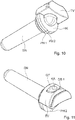
- the assembled state is in Fig. 10 shown. It can be seen that the holding device TV is suitable for receiving the suction nipple SN together with the holding body HK.
- an inverted drinking bucket TR is used for this, as in Fig. 12 is shown.
- the drinking bucket TR typically has at its bottom a bottom edge BR, which is formed as an annular structure below the bottom.
- this bottom edge BR can now, as in Fig. 13 is shown, the first breakthrough DB1 are performed, so that the suction device SV can be securely attached by means of the holder TV to the drinking bucket TR, so that it can be dried there after use.
- the first breakthrough DB1 can of course also be attached to other locations or devices and is not limited to the attachment shown by means of the Tränkeimers TR.
- a positioning aid in order to predetermine the orientation when inserting it into a drinking bin TR.
- This is related to, for example Fig. 10 described a first positioning aid PH1, which is arranged radially outwardly facing on the contact surface AF of Saugnuckels SN in the form of a nose.
- a corresponding second positioning aid is arranged in identical dimensions on the holding body HK.
- the first positioning aid PH1 and the second positioning aid PH2 now specify a position about the longitudinal axis LA when the suction device SV is inserted into a drinking bin TR.
- a further embodiment of a positioning aid is shown.
- the first positioning aid PH1 on Saugnuckel SN on the inside of the contact surface AF a short vertical segment, so that the rotational symmetry is broken about the longitudinal axis LA.
- the first positioning aid PH1 corresponds to a second positioning aid PH2, which is designed to correspond to the cylindrical extension ZF in the form of the second positioning aid PH2. Accordingly, the Saugnuckel SN can be applied only in a predetermined shape on the holding body HK.
Landscapes
- Life Sciences & Earth Sciences (AREA)
- Environmental Sciences (AREA)
- Animal Husbandry (AREA)
- Biodiversity & Conservation Biology (AREA)
- Hooks, Suction Cups, And Attachment By Adhesive Means (AREA)
Priority Applications (1)
| Application Number | Priority Date | Filing Date | Title |
|---|---|---|---|
| PL17169394T PL3243378T3 (pl) | 2016-05-10 | 2017-05-04 | Urządzenie do ssania i uchwyt do tego urządzenia |
Applications Claiming Priority (2)
| Application Number | Priority Date | Filing Date | Title |
|---|---|---|---|
| DE102016108580.4A DE102016108580A1 (de) | 2016-05-10 | 2016-05-10 | Saugvorrichtung |
| DE102016121642 | 2016-11-11 |
Publications (2)
| Publication Number | Publication Date |
|---|---|
| EP3243378A1 true EP3243378A1 (fr) | 2017-11-15 |
| EP3243378B1 EP3243378B1 (fr) | 2020-08-26 |
Family
ID=58671441
Family Applications (1)
| Application Number | Title | Priority Date | Filing Date |
|---|---|---|---|
| EP17169394.8A Active EP3243378B1 (fr) | 2016-05-10 | 2017-05-04 | Dispositif d'aspiration et support associé |
Country Status (2)
| Country | Link |
|---|---|
| EP (1) | EP3243378B1 (fr) |
| PL (1) | PL3243378T3 (fr) |
Citations (10)
| Publication number | Priority date | Publication date | Assignee | Title |
|---|---|---|---|---|
| US2516730A (en) | 1946-03-20 | 1950-07-25 | Mutual Products Company | Suckling device for calves |
| US2652027A (en) | 1950-11-28 | 1953-09-15 | James M Coyner | Nipple-equipped feeder pail |
| US2695007A (en) | 1953-12-01 | 1954-11-23 | Allover Mfg Co | Calf feeder pail assembly |
| DE8712611U1 (de) | 1987-09-10 | 1987-11-19 | Hinterkopf, Adolf, 7900 Ulm | Eimer, insbesondere zum Tränken von Tieren |
| US5638769A (en) * | 1993-03-03 | 1997-06-17 | Robert Dymock McIntyre | Teat |
| EP0958740A2 (fr) * | 1998-05-13 | 1999-11-24 | Marchioro S.p.A. Stampaggio Materie Plastiche | Distributeur d'eau et/ou d'aliments liquides pour petits animaux domestiques |
| US20100292637A1 (en) * | 2008-08-06 | 2010-11-18 | David Sokal | Device and method for delivering an agent into breast milk while breastfeeding |
| DE102011105853B3 (de) | 2011-06-28 | 2012-07-26 | Josef Müller | Viehtränkeventilanordnung |
| EP2160942B1 (fr) | 2008-09-05 | 2014-04-09 | Josef Strasser | Dispositif de soupape pour récipient de boisson par aspiration et seau de boisson par aspiration |
| DE202014103535U1 (de) | 2014-07-30 | 2014-08-12 | Albert Kerbl Gmbh | Viehsäugvorrichtung |
-
2017
- 2017-05-04 PL PL17169394T patent/PL3243378T3/pl unknown
- 2017-05-04 EP EP17169394.8A patent/EP3243378B1/fr active Active
Patent Citations (10)
| Publication number | Priority date | Publication date | Assignee | Title |
|---|---|---|---|---|
| US2516730A (en) | 1946-03-20 | 1950-07-25 | Mutual Products Company | Suckling device for calves |
| US2652027A (en) | 1950-11-28 | 1953-09-15 | James M Coyner | Nipple-equipped feeder pail |
| US2695007A (en) | 1953-12-01 | 1954-11-23 | Allover Mfg Co | Calf feeder pail assembly |
| DE8712611U1 (de) | 1987-09-10 | 1987-11-19 | Hinterkopf, Adolf, 7900 Ulm | Eimer, insbesondere zum Tränken von Tieren |
| US5638769A (en) * | 1993-03-03 | 1997-06-17 | Robert Dymock McIntyre | Teat |
| EP0958740A2 (fr) * | 1998-05-13 | 1999-11-24 | Marchioro S.p.A. Stampaggio Materie Plastiche | Distributeur d'eau et/ou d'aliments liquides pour petits animaux domestiques |
| US20100292637A1 (en) * | 2008-08-06 | 2010-11-18 | David Sokal | Device and method for delivering an agent into breast milk while breastfeeding |
| EP2160942B1 (fr) | 2008-09-05 | 2014-04-09 | Josef Strasser | Dispositif de soupape pour récipient de boisson par aspiration et seau de boisson par aspiration |
| DE102011105853B3 (de) | 2011-06-28 | 2012-07-26 | Josef Müller | Viehtränkeventilanordnung |
| DE202014103535U1 (de) | 2014-07-30 | 2014-08-12 | Albert Kerbl Gmbh | Viehsäugvorrichtung |
Also Published As
| Publication number | Publication date |
|---|---|
| PL3243378T3 (pl) | 2020-11-30 |
| EP3243378B1 (fr) | 2020-08-26 |
Similar Documents
| Publication | Publication Date | Title |
|---|---|---|
| EP1989937A2 (fr) | Unité de traie destinée à traire un animal | |
| WO2008138862A2 (fr) | Tuyau à lait pour un dispositif de traite | |
| DE202006012493U1 (de) | Befestigungseinrichtung mit Toleranzausgleich | |
| DE102007037242A1 (de) | Befestigungseinrichtung mit Toleranzausgleich | |
| EP1280399B2 (fr) | Gaine pour tuyau flexible de traite | |
| EP1728422B1 (fr) | Mangeoire pour volaille | |
| DE102005040275A1 (de) | Fluiddichte Schlauchverbindung in der Melktechnik sowie Schlauch, insbesondere Milchschlauch und Pulsatorschlauch | |
| EP2540158B1 (fr) | Agencement de soupape de tetine | |
| EP2015684B1 (fr) | Foret destiné à réaliser des trous dans le tissu osseux avec pièce de retenue et mèche | |
| EP1480511B9 (fr) | Piece collectrice de lait comportant un element de support de point de courbure permettant une courbure definie d'un tuyau flexible a lait | |
| EP3243378B1 (fr) | Dispositif d'aspiration et support associé | |
| DE102016108580A1 (de) | Saugvorrichtung | |
| DE102012019763B4 (de) | Spülvorrichtung zur Innenspülung und Halterung medizinischer Geräte | |
| EP3014988B1 (fr) | Système de tétine pour un abreuvoir automatique | |
| DE102016215633B4 (de) | Melkbecherhülse und modulares Melkbecherhülsensystem | |
| DE102007044720B3 (de) | Aufclipsbarer Schutzkörper | |
| DE3217865A1 (de) | Anordnung an einem milchschlauch, der einen zitzenbecher mit einem milchsammelstueck verbindet | |
| WO2008043820A1 (fr) | Douille de gobelet trayeur et gobelet trayeur pour traire un animal | |
| DE10323565A1 (de) | Gerät zur Spülung eines menschlichen Ohres | |
| EP3831200A1 (fr) | Seau d'abreuvement et dispositif d'aspiration | |
| EP2339913B1 (fr) | Dispositif et procédé de montage d'un morceau de tuyau destiné à des denrées alimentaires | |
| DE102016121665A1 (de) | Tränkeimer | |
| EP2672808B1 (fr) | Système comportant un manchon trayeur avec un tuyau à lait et un dispositif de ventilation, et un gobelet trayeur associé | |
| DE3022555C2 (de) | Zweiraum-Melkbecher | |
| WO2023227153A1 (fr) | Dispositif pour distribuer un liquide à des volailles d'élevage industriel |
Legal Events
| Date | Code | Title | Description |
|---|---|---|---|
| PUAI | Public reference made under article 153(3) epc to a published international application that has entered the european phase |
Free format text: ORIGINAL CODE: 0009012 |
|
| STAA | Information on the status of an ep patent application or granted ep patent |
Free format text: STATUS: THE APPLICATION HAS BEEN PUBLISHED |
|
| AK | Designated contracting states |
Kind code of ref document: A1 Designated state(s): AL AT BE BG CH CY CZ DE DK EE ES FI FR GB GR HR HU IE IS IT LI LT LU LV MC MK MT NL NO PL PT RO RS SE SI SK SM TR |
|
| AX | Request for extension of the european patent |
Extension state: BA ME |
|
| STAA | Information on the status of an ep patent application or granted ep patent |
Free format text: STATUS: REQUEST FOR EXAMINATION WAS MADE |
|
| 17P | Request for examination filed |
Effective date: 20180515 |
|
| RBV | Designated contracting states (corrected) |
Designated state(s): AL AT BE BG CH CY CZ DE DK EE ES FI FR GB GR HR HU IE IS IT LI LT LU LV MC MK MT NL NO PL PT RO RS SE SI SK SM TR |
|
| STAA | Information on the status of an ep patent application or granted ep patent |
Free format text: STATUS: EXAMINATION IS IN PROGRESS |
|
| 17Q | First examination report despatched |
Effective date: 20181206 |
|
| GRAP | Despatch of communication of intention to grant a patent |
Free format text: ORIGINAL CODE: EPIDOSNIGR1 |
|
| STAA | Information on the status of an ep patent application or granted ep patent |
Free format text: STATUS: GRANT OF PATENT IS INTENDED |
|
| INTG | Intention to grant announced |
Effective date: 20200317 |
|
| GRAS | Grant fee paid |
Free format text: ORIGINAL CODE: EPIDOSNIGR3 |
|
| GRAA | (expected) grant |
Free format text: ORIGINAL CODE: 0009210 |
|
| STAA | Information on the status of an ep patent application or granted ep patent |
Free format text: STATUS: THE PATENT HAS BEEN GRANTED |
|
| RAP1 | Party data changed (applicant data changed or rights of an application transferred) |
Owner name: H I K O GMBH |
|
| AK | Designated contracting states |
Kind code of ref document: B1 Designated state(s): AL AT BE BG CH CY CZ DE DK EE ES FI FR GB GR HR HU IE IS IT LI LT LU LV MC MK MT NL NO PL PT RO RS SE SI SK SM TR |
|
| REG | Reference to a national code |
Ref country code: GB Ref legal event code: FG4D Free format text: NOT ENGLISH |
|
| REG | Reference to a national code |
Ref country code: CH Ref legal event code: EP |
|
| REG | Reference to a national code |
Ref country code: AT Ref legal event code: REF Ref document number: 1305472 Country of ref document: AT Kind code of ref document: T Effective date: 20200915 |
|
| REG | Reference to a national code |
Ref country code: IE Ref legal event code: FG4D Free format text: LANGUAGE OF EP DOCUMENT: GERMAN |
|
| REG | Reference to a national code |
Ref country code: DE Ref legal event code: R096 Ref document number: 502017006889 Country of ref document: DE |
|
| REG | Reference to a national code |
Ref country code: NL Ref legal event code: FP |
|
| REG | Reference to a national code |
Ref country code: LT Ref legal event code: MG4D |
|
| PG25 | Lapsed in a contracting state [announced via postgrant information from national office to epo] |
Ref country code: PT Free format text: LAPSE BECAUSE OF FAILURE TO SUBMIT A TRANSLATION OF THE DESCRIPTION OR TO PAY THE FEE WITHIN THE PRESCRIBED TIME-LIMIT Effective date: 20201228 Ref country code: LT Free format text: LAPSE BECAUSE OF FAILURE TO SUBMIT A TRANSLATION OF THE DESCRIPTION OR TO PAY THE FEE WITHIN THE PRESCRIBED TIME-LIMIT Effective date: 20200826 Ref country code: BG Free format text: LAPSE BECAUSE OF FAILURE TO SUBMIT A TRANSLATION OF THE DESCRIPTION OR TO PAY THE FEE WITHIN THE PRESCRIBED TIME-LIMIT Effective date: 20201126 Ref country code: NO Free format text: LAPSE BECAUSE OF FAILURE TO SUBMIT A TRANSLATION OF THE DESCRIPTION OR TO PAY THE FEE WITHIN THE PRESCRIBED TIME-LIMIT Effective date: 20201126 Ref country code: HR Free format text: LAPSE BECAUSE OF FAILURE TO SUBMIT A TRANSLATION OF THE DESCRIPTION OR TO PAY THE FEE WITHIN THE PRESCRIBED TIME-LIMIT Effective date: 20200826 Ref country code: FI Free format text: LAPSE BECAUSE OF FAILURE TO SUBMIT A TRANSLATION OF THE DESCRIPTION OR TO PAY THE FEE WITHIN THE PRESCRIBED TIME-LIMIT Effective date: 20200826 Ref country code: GR Free format text: LAPSE BECAUSE OF FAILURE TO SUBMIT A TRANSLATION OF THE DESCRIPTION OR TO PAY THE FEE WITHIN THE PRESCRIBED TIME-LIMIT Effective date: 20201127 Ref country code: SE Free format text: LAPSE BECAUSE OF FAILURE TO SUBMIT A TRANSLATION OF THE DESCRIPTION OR TO PAY THE FEE WITHIN THE PRESCRIBED TIME-LIMIT Effective date: 20200826 |
|
| PG25 | Lapsed in a contracting state [announced via postgrant information from national office to epo] |
Ref country code: RS Free format text: LAPSE BECAUSE OF FAILURE TO SUBMIT A TRANSLATION OF THE DESCRIPTION OR TO PAY THE FEE WITHIN THE PRESCRIBED TIME-LIMIT Effective date: 20200826 Ref country code: LV Free format text: LAPSE BECAUSE OF FAILURE TO SUBMIT A TRANSLATION OF THE DESCRIPTION OR TO PAY THE FEE WITHIN THE PRESCRIBED TIME-LIMIT Effective date: 20200826 Ref country code: IS Free format text: LAPSE BECAUSE OF FAILURE TO SUBMIT A TRANSLATION OF THE DESCRIPTION OR TO PAY THE FEE WITHIN THE PRESCRIBED TIME-LIMIT Effective date: 20201226 |
|
| PG25 | Lapsed in a contracting state [announced via postgrant information from national office to epo] |
Ref country code: DK Free format text: LAPSE BECAUSE OF FAILURE TO SUBMIT A TRANSLATION OF THE DESCRIPTION OR TO PAY THE FEE WITHIN THE PRESCRIBED TIME-LIMIT Effective date: 20200826 Ref country code: CZ Free format text: LAPSE BECAUSE OF FAILURE TO SUBMIT A TRANSLATION OF THE DESCRIPTION OR TO PAY THE FEE WITHIN THE PRESCRIBED TIME-LIMIT Effective date: 20200826 Ref country code: RO Free format text: LAPSE BECAUSE OF FAILURE TO SUBMIT A TRANSLATION OF THE DESCRIPTION OR TO PAY THE FEE WITHIN THE PRESCRIBED TIME-LIMIT Effective date: 20200826 Ref country code: SM Free format text: LAPSE BECAUSE OF FAILURE TO SUBMIT A TRANSLATION OF THE DESCRIPTION OR TO PAY THE FEE WITHIN THE PRESCRIBED TIME-LIMIT Effective date: 20200826 Ref country code: EE Free format text: LAPSE BECAUSE OF FAILURE TO SUBMIT A TRANSLATION OF THE DESCRIPTION OR TO PAY THE FEE WITHIN THE PRESCRIBED TIME-LIMIT Effective date: 20200826 |
|
| REG | Reference to a national code |
Ref country code: DE Ref legal event code: R097 Ref document number: 502017006889 Country of ref document: DE |
|
| PG25 | Lapsed in a contracting state [announced via postgrant information from national office to epo] |
Ref country code: AL Free format text: LAPSE BECAUSE OF FAILURE TO SUBMIT A TRANSLATION OF THE DESCRIPTION OR TO PAY THE FEE WITHIN THE PRESCRIBED TIME-LIMIT Effective date: 20200826 Ref country code: ES Free format text: LAPSE BECAUSE OF FAILURE TO SUBMIT A TRANSLATION OF THE DESCRIPTION OR TO PAY THE FEE WITHIN THE PRESCRIBED TIME-LIMIT Effective date: 20200826 |
|
| PG25 | Lapsed in a contracting state [announced via postgrant information from national office to epo] |
Ref country code: SK Free format text: LAPSE BECAUSE OF FAILURE TO SUBMIT A TRANSLATION OF THE DESCRIPTION OR TO PAY THE FEE WITHIN THE PRESCRIBED TIME-LIMIT Effective date: 20200826 |
|
| PLBE | No opposition filed within time limit |
Free format text: ORIGINAL CODE: 0009261 |
|
| STAA | Information on the status of an ep patent application or granted ep patent |
Free format text: STATUS: NO OPPOSITION FILED WITHIN TIME LIMIT |
|
| PG25 | Lapsed in a contracting state [announced via postgrant information from national office to epo] |
Ref country code: IT Free format text: LAPSE BECAUSE OF FAILURE TO SUBMIT A TRANSLATION OF THE DESCRIPTION OR TO PAY THE FEE WITHIN THE PRESCRIBED TIME-LIMIT Effective date: 20200826 |
|
| 26N | No opposition filed |
Effective date: 20210527 |
|
| PG25 | Lapsed in a contracting state [announced via postgrant information from national office to epo] |
Ref country code: SI Free format text: LAPSE BECAUSE OF FAILURE TO SUBMIT A TRANSLATION OF THE DESCRIPTION OR TO PAY THE FEE WITHIN THE PRESCRIBED TIME-LIMIT Effective date: 20200826 |
|
| REG | Reference to a national code |
Ref country code: CH Ref legal event code: PL |
|
| PG25 | Lapsed in a contracting state [announced via postgrant information from national office to epo] |
Ref country code: MC Free format text: LAPSE BECAUSE OF FAILURE TO SUBMIT A TRANSLATION OF THE DESCRIPTION OR TO PAY THE FEE WITHIN THE PRESCRIBED TIME-LIMIT Effective date: 20200826 Ref country code: LU Free format text: LAPSE BECAUSE OF NON-PAYMENT OF DUE FEES Effective date: 20210504 Ref country code: LI Free format text: LAPSE BECAUSE OF NON-PAYMENT OF DUE FEES Effective date: 20210531 Ref country code: CH Free format text: LAPSE BECAUSE OF NON-PAYMENT OF DUE FEES Effective date: 20210531 |
|
| REG | Reference to a national code |
Ref country code: BE Ref legal event code: MM Effective date: 20210531 |
|
| PG25 | Lapsed in a contracting state [announced via postgrant information from national office to epo] |
Ref country code: IE Free format text: LAPSE BECAUSE OF NON-PAYMENT OF DUE FEES Effective date: 20210504 |
|
| PG25 | Lapsed in a contracting state [announced via postgrant information from national office to epo] |
Ref country code: BE Free format text: LAPSE BECAUSE OF NON-PAYMENT OF DUE FEES Effective date: 20210531 |
|
| PG25 | Lapsed in a contracting state [announced via postgrant information from national office to epo] |
Ref country code: HU Free format text: LAPSE BECAUSE OF FAILURE TO SUBMIT A TRANSLATION OF THE DESCRIPTION OR TO PAY THE FEE WITHIN THE PRESCRIBED TIME-LIMIT; INVALID AB INITIO Effective date: 20170504 |
|
| PG25 | Lapsed in a contracting state [announced via postgrant information from national office to epo] |
Ref country code: CY Free format text: LAPSE BECAUSE OF FAILURE TO SUBMIT A TRANSLATION OF THE DESCRIPTION OR TO PAY THE FEE WITHIN THE PRESCRIBED TIME-LIMIT Effective date: 20200826 |
|
| REG | Reference to a national code |
Ref country code: AT Ref legal event code: MM01 Ref document number: 1305472 Country of ref document: AT Kind code of ref document: T Effective date: 20220504 |
|
| PG25 | Lapsed in a contracting state [announced via postgrant information from national office to epo] |
Ref country code: AT Free format text: LAPSE BECAUSE OF NON-PAYMENT OF DUE FEES Effective date: 20220504 |
|
| PGFP | Annual fee paid to national office [announced via postgrant information from national office to epo] |
Ref country code: NL Payment date: 20230519 Year of fee payment: 7 Ref country code: FR Payment date: 20230517 Year of fee payment: 7 Ref country code: DE Payment date: 20230531 Year of fee payment: 7 |
|
| PGFP | Annual fee paid to national office [announced via postgrant information from national office to epo] |
Ref country code: PL Payment date: 20230420 Year of fee payment: 7 |
|
| PGFP | Annual fee paid to national office [announced via postgrant information from national office to epo] |
Ref country code: GB Payment date: 20230522 Year of fee payment: 7 |
|
| PG25 | Lapsed in a contracting state [announced via postgrant information from national office to epo] |
Ref country code: MK Free format text: LAPSE BECAUSE OF FAILURE TO SUBMIT A TRANSLATION OF THE DESCRIPTION OR TO PAY THE FEE WITHIN THE PRESCRIBED TIME-LIMIT Effective date: 20200826 |