EP3243103B1 - Achromatischer phasenmodulator, beruhend auf flüssigkristallen - Google Patents
Achromatischer phasenmodulator, beruhend auf flüssigkristallen Download PDFInfo
- Publication number
- EP3243103B1 EP3243103B1 EP15701593.4A EP15701593A EP3243103B1 EP 3243103 B1 EP3243103 B1 EP 3243103B1 EP 15701593 A EP15701593 A EP 15701593A EP 3243103 B1 EP3243103 B1 EP 3243103B1
- Authority
- EP
- European Patent Office
- Prior art keywords
- liquid crystal
- crystal element
- pair
- crystal elements
- element group
- Prior art date
- Legal status (The legal status is an assumption and is not a legal conclusion. Google has not performed a legal analysis and makes no representation as to the accuracy of the status listed.)
- Active
Links
- 239000004973 liquid crystal related substance Substances 0.000 title claims description 853
- 239000000463 material Substances 0.000 claims description 105
- 239000000758 substrate Substances 0.000 claims description 42
- 230000007423 decrease Effects 0.000 claims description 17
- 239000004988 Nematic liquid crystal Substances 0.000 claims description 7
- 230000014509 gene expression Effects 0.000 description 53
- 230000010287 polarization Effects 0.000 description 23
- 238000004364 calculation method Methods 0.000 description 13
- 238000000034 method Methods 0.000 description 13
- 230000010363 phase shift Effects 0.000 description 9
- 239000011521 glass Substances 0.000 description 8
- 230000003287 optical effect Effects 0.000 description 8
- 238000004088 simulation Methods 0.000 description 8
- 238000010586 diagram Methods 0.000 description 7
- 230000005540 biological transmission Effects 0.000 description 5
- 239000006185 dispersion Substances 0.000 description 5
- 238000005259 measurement Methods 0.000 description 5
- 239000011159 matrix material Substances 0.000 description 4
- 230000003247 decreasing effect Effects 0.000 description 3
- 238000005457 optimization Methods 0.000 description 3
- 239000004642 Polyimide Substances 0.000 description 2
- 239000011248 coating agent Substances 0.000 description 2
- 238000000576 coating method Methods 0.000 description 2
- 210000002858 crystal cell Anatomy 0.000 description 2
- 239000007788 liquid Substances 0.000 description 2
- 238000004519 manufacturing process Methods 0.000 description 2
- 229920001721 polyimide Polymers 0.000 description 2
- 238000003860 storage Methods 0.000 description 2
- 239000000853 adhesive Substances 0.000 description 1
- 230000001070 adhesive effect Effects 0.000 description 1
- 230000001419 dependent effect Effects 0.000 description 1
- 238000001514 detection method Methods 0.000 description 1
- 230000000694 effects Effects 0.000 description 1
- AMGQUBHHOARCQH-UHFFFAOYSA-N indium;oxotin Chemical compound [In].[Sn]=O AMGQUBHHOARCQH-UHFFFAOYSA-N 0.000 description 1
- 229920000642 polymer Polymers 0.000 description 1
- 230000000750 progressive effect Effects 0.000 description 1
- 238000007789 sealing Methods 0.000 description 1
Images


Classifications
-
- G—PHYSICS
- G02—OPTICS
- G02F—OPTICAL DEVICES OR ARRANGEMENTS FOR THE CONTROL OF LIGHT BY MODIFICATION OF THE OPTICAL PROPERTIES OF THE MEDIA OF THE ELEMENTS INVOLVED THEREIN; NON-LINEAR OPTICS; FREQUENCY-CHANGING OF LIGHT; OPTICAL LOGIC ELEMENTS; OPTICAL ANALOGUE/DIGITAL CONVERTERS
- G02F1/00—Devices or arrangements for the control of the intensity, colour, phase, polarisation or direction of light arriving from an independent light source, e.g. switching, gating or modulating; Non-linear optics
- G02F1/01—Devices or arrangements for the control of the intensity, colour, phase, polarisation or direction of light arriving from an independent light source, e.g. switching, gating or modulating; Non-linear optics for the control of the intensity, phase, polarisation or colour
- G02F1/13—Devices or arrangements for the control of the intensity, colour, phase, polarisation or direction of light arriving from an independent light source, e.g. switching, gating or modulating; Non-linear optics for the control of the intensity, phase, polarisation or colour based on liquid crystals, e.g. single liquid crystal display cells
- G02F1/137—Devices or arrangements for the control of the intensity, colour, phase, polarisation or direction of light arriving from an independent light source, e.g. switching, gating or modulating; Non-linear optics for the control of the intensity, phase, polarisation or colour based on liquid crystals, e.g. single liquid crystal display cells characterised by the electro-optical or magneto-optical effect, e.g. field-induced phase transition, orientation effect, guest-host interaction or dynamic scattering
- G02F1/139—Devices or arrangements for the control of the intensity, colour, phase, polarisation or direction of light arriving from an independent light source, e.g. switching, gating or modulating; Non-linear optics for the control of the intensity, phase, polarisation or colour based on liquid crystals, e.g. single liquid crystal display cells characterised by the electro-optical or magneto-optical effect, e.g. field-induced phase transition, orientation effect, guest-host interaction or dynamic scattering based on orientation effects in which the liquid crystal remains transparent
- G02F1/1393—Devices or arrangements for the control of the intensity, colour, phase, polarisation or direction of light arriving from an independent light source, e.g. switching, gating or modulating; Non-linear optics for the control of the intensity, phase, polarisation or colour based on liquid crystals, e.g. single liquid crystal display cells characterised by the electro-optical or magneto-optical effect, e.g. field-induced phase transition, orientation effect, guest-host interaction or dynamic scattering based on orientation effects in which the liquid crystal remains transparent the birefringence of the liquid crystal being electrically controlled, e.g. ECB-, DAP-, HAN-, PI-LC cells
-
- G—PHYSICS
- G02—OPTICS
- G02F—OPTICAL DEVICES OR ARRANGEMENTS FOR THE CONTROL OF LIGHT BY MODIFICATION OF THE OPTICAL PROPERTIES OF THE MEDIA OF THE ELEMENTS INVOLVED THEREIN; NON-LINEAR OPTICS; FREQUENCY-CHANGING OF LIGHT; OPTICAL LOGIC ELEMENTS; OPTICAL ANALOGUE/DIGITAL CONVERTERS
- G02F1/00—Devices or arrangements for the control of the intensity, colour, phase, polarisation or direction of light arriving from an independent light source, e.g. switching, gating or modulating; Non-linear optics
- G02F1/01—Devices or arrangements for the control of the intensity, colour, phase, polarisation or direction of light arriving from an independent light source, e.g. switching, gating or modulating; Non-linear optics for the control of the intensity, phase, polarisation or colour
- G02F1/13—Devices or arrangements for the control of the intensity, colour, phase, polarisation or direction of light arriving from an independent light source, e.g. switching, gating or modulating; Non-linear optics for the control of the intensity, phase, polarisation or colour based on liquid crystals, e.g. single liquid crystal display cells
- G02F1/133—Constructional arrangements; Operation of liquid crystal cells; Circuit arrangements
- G02F1/1333—Constructional arrangements; Manufacturing methods
- G02F1/1347—Arrangement of liquid crystal layers or cells in which the final condition of one light beam is achieved by the addition of the effects of two or more layers or cells
- G02F1/13471—Arrangement of liquid crystal layers or cells in which the final condition of one light beam is achieved by the addition of the effects of two or more layers or cells in which all the liquid crystal cells or layers remain transparent, e.g. FLC, ECB, DAP, HAN, TN, STN, SBE-LC cells
-
- G—PHYSICS
- G02—OPTICS
- G02F—OPTICAL DEVICES OR ARRANGEMENTS FOR THE CONTROL OF LIGHT BY MODIFICATION OF THE OPTICAL PROPERTIES OF THE MEDIA OF THE ELEMENTS INVOLVED THEREIN; NON-LINEAR OPTICS; FREQUENCY-CHANGING OF LIGHT; OPTICAL LOGIC ELEMENTS; OPTICAL ANALOGUE/DIGITAL CONVERTERS
- G02F1/00—Devices or arrangements for the control of the intensity, colour, phase, polarisation or direction of light arriving from an independent light source, e.g. switching, gating or modulating; Non-linear optics
- G02F1/01—Devices or arrangements for the control of the intensity, colour, phase, polarisation or direction of light arriving from an independent light source, e.g. switching, gating or modulating; Non-linear optics for the control of the intensity, phase, polarisation or colour
- G02F1/13—Devices or arrangements for the control of the intensity, colour, phase, polarisation or direction of light arriving from an independent light source, e.g. switching, gating or modulating; Non-linear optics for the control of the intensity, phase, polarisation or colour based on liquid crystals, e.g. single liquid crystal display cells
- G02F1/137—Devices or arrangements for the control of the intensity, colour, phase, polarisation or direction of light arriving from an independent light source, e.g. switching, gating or modulating; Non-linear optics for the control of the intensity, phase, polarisation or colour based on liquid crystals, e.g. single liquid crystal display cells characterised by the electro-optical or magneto-optical effect, e.g. field-induced phase transition, orientation effect, guest-host interaction or dynamic scattering
- G02F1/139—Devices or arrangements for the control of the intensity, colour, phase, polarisation or direction of light arriving from an independent light source, e.g. switching, gating or modulating; Non-linear optics for the control of the intensity, phase, polarisation or colour based on liquid crystals, e.g. single liquid crystal display cells characterised by the electro-optical or magneto-optical effect, e.g. field-induced phase transition, orientation effect, guest-host interaction or dynamic scattering based on orientation effects in which the liquid crystal remains transparent
- G02F1/1392—Devices or arrangements for the control of the intensity, colour, phase, polarisation or direction of light arriving from an independent light source, e.g. switching, gating or modulating; Non-linear optics for the control of the intensity, phase, polarisation or colour based on liquid crystals, e.g. single liquid crystal display cells characterised by the electro-optical or magneto-optical effect, e.g. field-induced phase transition, orientation effect, guest-host interaction or dynamic scattering based on orientation effects in which the liquid crystal remains transparent using a field-induced sign-reversal of the dielectric anisotropy
-
- G—PHYSICS
- G02—OPTICS
- G02F—OPTICAL DEVICES OR ARRANGEMENTS FOR THE CONTROL OF LIGHT BY MODIFICATION OF THE OPTICAL PROPERTIES OF THE MEDIA OF THE ELEMENTS INVOLVED THEREIN; NON-LINEAR OPTICS; FREQUENCY-CHANGING OF LIGHT; OPTICAL LOGIC ELEMENTS; OPTICAL ANALOGUE/DIGITAL CONVERTERS
- G02F2203/00—Function characteristic
- G02F2203/04—Function characteristic wavelength independent
-
- G—PHYSICS
- G02—OPTICS
- G02F—OPTICAL DEVICES OR ARRANGEMENTS FOR THE CONTROL OF LIGHT BY MODIFICATION OF THE OPTICAL PROPERTIES OF THE MEDIA OF THE ELEMENTS INVOLVED THEREIN; NON-LINEAR OPTICS; FREQUENCY-CHANGING OF LIGHT; OPTICAL LOGIC ELEMENTS; OPTICAL ANALOGUE/DIGITAL CONVERTERS
- G02F2203/00—Function characteristic
- G02F2203/05—Function characteristic wavelength dependent
-
- G—PHYSICS
- G02—OPTICS
- G02F—OPTICAL DEVICES OR ARRANGEMENTS FOR THE CONTROL OF LIGHT BY MODIFICATION OF THE OPTICAL PROPERTIES OF THE MEDIA OF THE ELEMENTS INVOLVED THEREIN; NON-LINEAR OPTICS; FREQUENCY-CHANGING OF LIGHT; OPTICAL LOGIC ELEMENTS; OPTICAL ANALOGUE/DIGITAL CONVERTERS
- G02F2203/00—Function characteristic
- G02F2203/06—Polarisation independent
-
- G—PHYSICS
- G02—OPTICS
- G02F—OPTICAL DEVICES OR ARRANGEMENTS FOR THE CONTROL OF LIGHT BY MODIFICATION OF THE OPTICAL PROPERTIES OF THE MEDIA OF THE ELEMENTS INVOLVED THEREIN; NON-LINEAR OPTICS; FREQUENCY-CHANGING OF LIGHT; OPTICAL LOGIC ELEMENTS; OPTICAL ANALOGUE/DIGITAL CONVERTERS
- G02F2203/00—Function characteristic
- G02F2203/50—Phase-only modulation
Definitions
- the present invention relates to an achromatic phase modulator that modulates the phase of incident light by using liquid crystal elements and outputs the light having undergone the phase modulation.
- Patent Literature 1 Japanese laid open patent publication No. 2009-14778 A further exemplary modulator is disclosed in WO 96/10210 A1 .
- Non- Patent Literature 1 Yi-Hsin Lin, Yung-Hsun Wu, Yue Zhao, Jiyu Fang, Zhibing Ge, and Shin-Tson Wu; "Polarization-independent liquid crystal phase modulator using polymer-separated double layered structure"; Optics Express; (USA); The Optical Society; October 31, 2005; Vol.13, No.22; p. 8746-8752
- phase modulator disclosed in patent literature 1 modulates a phase of an incident light after converting from non-polarized light to linearly polarized light.
- Phase modulation quantity by the phase modulator disclosed in patent literature 1 change with wavelength of the incident light.
- the phase modulator disclosed in non-patent literature 1 can modulate a phase of an incident light independently to a polarization state, phase modulation quantity change with wavelength of the incident light. Therefore, only a single wavelength light can be used for these phase modulators, and it means that it is not possible for these phase modulator to achieve phase modulation of a color image formed with light originating from, for instance, a white light source. For this reason, achromatic phase modulators capable of achieving a substantially uniform phase modulation quantity in correspondence to light at any wavelength within a wide wavelength range, such as the visible light wavelength range, are of great interest.
- an achromatic phase modulator that modulates phase of an incident light and outputs the light having undergone phase modulation, comprises: a plurality of liquid crystal elements disposed in series on a light path of the incident light, which are composed of liquid crystal materials; and a control unit for applying drive electric signals to the liquid crystal elements so as to achieve achromatic phase modulation for the incident light, wherein: the plurality of liquid crystal element comprises at least a first liquid crystal element group composed of a pair of liquid crystal elements both of which liquid crystal materials have a first refractive index wavelength dependence characteristics and a second liquid crystal element group composed of a pair of liquid crystal elements both of which liquid crystal materials have a second refractive index wavelength dependence characteristics; and thicknesses of both of liquid crystal material layers of the liquid crystal elements constituting the first liquid crystal element group are substantially the same in each other, and thicknesses of both of liquid crystal material layers of the liquid crystal elements constituting the second liquid
- an alignment direction of liquid crystal molecules of one of the liquid crystal element in the pair of liquid crystal elements constituting the first liquid crystal element group, can be altered in a plane including a first alignment direction substantially parallel to a direction in which the incident light advances, and a second alignment direction perpendicular to the first alignment direction, and an alignment direction of liquid crystal molecules of another of the liquid crystal element can be altered in a plane including the first alignment direction and a third alignment direction perpendicular to both of the first alignment direction and the second alignment direction, in the pair of liquid crystal elements constituting the second liquid crystal element group, an alignment direction of liquid crystal molecules of one of the liquid crystal element can be altered in a plane including the first alignment direction and a fourth alignment direction perpendicular to the first alignment direction, and an alignment direction of liquid crystal molecules of another of the liquid crystal element can be altered in a plane including the first alignment direction and a fifth alignment direction perpendicular to both of the first alignment direction and the fourth
- achromatic phase modulator in the achromatic phase modulator according to the second embodiment, it is preferred that in each of the plurality of the liquid crystal elements, by changing the alignment directions of the liquid crystal molecules can be set individually, a first modulation condition under which a first modulation quantity is achieved and a second modulation condition under which a second modulation quantity different from the first modulation quantity are achieved, in correspondence to the applying drive electric signals to each of the liquid crystal elements; and for light having a given wavelength, in one of the first and second liquid crystal element groups, an average of refractive indices of the pair of liquid crystal elements in the first alignment condition is greater than an average of refractive indices of the pair of liquid crystal elements in the second alignment condition, and in the other of the first and second liquid crystal element groups, an average of refractive indices of the pair of liquid crystal elements in the first alignment condition is smaller than an average of refractive indices of the pair of liquid crystal elements in the second alignment condition.
- both of the alignment directions of the pair of liquid crystal molecules constituting the first liquid crystal element group are in the first alignment direction, whereas one of the alignment directions of the pair of liquid crystal molecules constituting the second liquid crystal element group is in the fourth alignment direction and the other of the alignment directions of the pair of liquid crystal molecules constituting the second liquid crystal element group is in the fifth alignment direction.
- the second alignment direction is identical to the fourth alignment direction and the third alignment direction is identical to the fifth alignment direction.
- the achromatic phase modulator further comprises the third liquid crystal element group composed of a pair of liquid crystal elements, disposed in series on the light path of the incident light, both of which liquid crystal materials have a third refractive index wavelength dependence characteristics, wherein: in the pair of liquid crystal elements constituting the third liquid crystal element group, an alignment direction of liquid crystal molecules of one of the liquid crystal element can be altered in a plane including the first alignment direction and a sixth alignment direction perpendicular to the first alignment direction, and an alignment direction of liquid crystal molecules of another of the liquid crystal element can be altered in a plane including the first alignment direction and a seventh alignment direction perpendicular to both of the first alignment direction and the sixth alignment direction; and thicknesses of both of liquid crystal material layers of the liquid crystal elements constituting the third liquid crystal element group are substantially the same in each other.
- the alignment directions of the liquid crystal molecules can be set individually to a first alignment condition under which a first modulation quantity is achieved and to a second modulation condition under which a second modulation quantity different from the first modulation quantity is achieved, in correspondence to the applying drive electric signals to each of the liquid crystal elements; and for light having a given wavelength, in two of the first, second and third liquid crystal element groups, an average of refractive indices of the pair of liquid crystal elements in the first alignment condition is greater than an average of refractive indices of the pair of liquid crystal elements in the second alignment condition, and in remaining one of the first, second and third liquid crystal element groups, an average of refractive indices of the pair of liquid crystal elements in the first alignment condition is smaller than an average of refractive indices of the pair of liquid crystal elements in the second alignment condition, or in one of the first, second and third liquid crystal element groups
- the achromatic phase modulator according to the eleventh or sixth or seventh embodiment it is preferred that while the drive electric signal is not being applied to the each of the liquid crystal elements, all of the alignment directions of the pair of liquid crystal molecules constituting the first, second and third liquid crystal element groups are in the first alignment direction.
- the alignment directions among the second alignment direction, the fourth alignment direction and the sixth alignment direction are the same in each other, and at least two of the alignment directions among the third alignment direction, the fifth alignment direction and the seventh alignment direction are the same in each other.
- control unit applies substantially the same control electric signals to each of the pair of liquid crystal elements constituting in each of the liquid crystal elements.
- the incident light has a wavelength within a visible range
- the liquid crystal elements are all nematic liquid crystal elements.
- the pair of liquid crystal elements constituting thereof are positioned in series along the incident light advancing direction to each other.
- the pair of liquid crystal elements constituting thereof are positioned in contact with each other.
- the pair of liquid crystal elements constituting thereof build an integrated liquid crystal element having a pair of substrates and a layer, centrally located between the pair of substrates, separates thereby to each of the pair of liquid crystal elements.
- the integrated liquid crystal element is to be applied with single system drive electric signal.
- thicknesses of liquid crystal material layers at the liquid crystal elements are set so as to achieve any extents of phase modulation falling within the range between zero and the maximum phase modulation by controlling the drive electric signals to be applied to each of the liquid crystal elements.
- the drive electric signal is provided as a voltage.
- the thicknesses of the liquid crystal material layers at the liquid crystal elements constituting each of the liquid crystal element groups are all set equal to or less than 30 ⁇ m.
- the liquid crystal elements are each divided into a plurality of separate divisional liquid crystal areas arranged in a two-dimensional array; the divisional liquid crystal areas arrayed at one liquid crystal element corresponds to the divisional liquid crystal areas at another liquid crystal element; and the control means executes control so as to apply a drive electric signal individually to each of the divisional liquid crystal areas.
- an optical device comprises the achromatic phase modulator according to any one of the first through nineteenth embodiments.
- a haze is equal to 2% or less.
- the present disclosure also concerns an optical device comprising such achromatic phase modulator.
- the optical device might be one of an ophthalmic lens, an ocular visor, and sight optical systems
- the ophthalmic lens is a lens which is designed to fit a spectacles frame so as to protect the eye and/or correct the sight and can be a non-corrective (also called plano or afocal lens) or corrective ophthalmic lens.
- Corrective lens may be a unifocal, a bifocal, a trifocal or a progressive lens.
- An ocular visor is understood as such found in masks, goggles, helmets or other headgears, and being designed to be positioned in front of the eyes, here, goggles and masks refer to for example ski goggles or scuba or snorkelling masks, protection goggles, and other similar devices.
- the optical device according to the present disclosure can be an ophthalmic lens which has a curvature.
- the optical device according to the present disclosure has a haze equal 2% or less and preferably no greater than 0.4%.
- the haze value is measured by light transmission measurement using the Haze-Guard Plus ⁇ haze meter manufactured by BYK-Gardner (or a color difference meter) according to the method of ASTM D1003-00, which is incorporated herein in its entirety by reference. All references to "haze" values in this application are by this standard.
- the instrument is first calibrated according to the manufacturer's instructions. Next, the sample is placed on the transmission light beam of the pre-calibrated meter and the haze value is recorded from three different specimen locations and averaged.
- the present invention provides an achromatic phase modulator that is capable of executing achromatic phase modulation in conjunction with light including non-polarized light over a wide wavelength range.
- the phase modulator according to the embodiment of the present invention is configured by disposing a plurality of liquid crystal elements in an incident light advancing direction.
- an alignment direction of liquid crystal molecules can be altered in a plane including a direction perpendicular to a substrate and one direction parallel to the substrate in correspondence to a state of applying drive electric signals.
- Such liquid crystal element is called zero-twist liquid crystal element.
- FIG. 1(a) for vertical aligned element and 1(b) for anti-parallel aligned element.
- X axis is to be set in a direction perpendicular to the drawing sheet
- Y axis is to be set in a direction parallel to the drawing sheet
- Z axis is to be set in a direction along the incident light advancing.
- FIG.s 1(a) and 1(b) illustrate sectional views of the alignment of liquid crystal elements. It is to be noted that azimuthal alignment directions are parallel to the drawing sheet.
- reference numeral 1 and 2 respectively indicate a substrate and a liquid crystal material
- the ovals denoted with the reference numeral 3 depict liquid crystal molecules.
- the liquid crystal molecules inside the liquid crystal elements may be tilted along any direction between a direction perpendicular to the substrate surfaces and one direction parallel to the substrate.
- FIG. 1(a) illustrates the vertical aligned liquid crystal element having a negative dielectric anisotropy (N-type liquid crystal element) and FIG. 1(b) illustrates the anti-parallel aligned liquid crystal element having a positive dielectric anisotropy (P-type liquid crystal element).
- liquid crystal molecules are aligned along a direction perpendicular to the substrate during no drive electric signal (voltage, for example) is being applied. Whereas, liquid crystal molecules are aligned along one direction parallel to the substrate during sufficient drive electric signal (sufficient high voltage, for example) is being applied.
- liquid crystal molecules are aligned along one direction parallel to the substrate during no drive electric signal is being applied. Whereas, liquid crystal molecules are aligned along a direction perpendicular to the substrate during sufficient drive electric signal is being applied.
- the refractive index of the liquid crystal material with regard to incoming linearly polarized light changes in correspondence to the tilt angle of the liquid crystal molecule.
- refractive index of the liquid crystal element in which the liquid crystal molecules are aligned along a direction perpendicular to the substrate is different from that in which the liquid crystal molecules are aligned along one direction parallel to the substrate.
- the ordinary refractive index n o ( ⁇ ) of the liquid crystal material is smaller than the extraordinary refractive index n e ( ⁇ ) thereof.
- the effective refractive index corresponds to the refractive index experienced by the linearly polarized light as it passed through liquid crystal material, and its value is between n o ( ⁇ ) and n e ( ⁇ ).
- the refractive index of the liquid crystal element in which the liquid crystal molecules are aligned along a direction perpendicular to the substrate is to be represented as n o ( ⁇ ) and that in which the liquid crystal molecules are aligned along one direction parallel to the substrate is to be represented as n e ( ⁇ ).
- Both of n o ( ⁇ ) and n e ( ⁇ ) change in correspondence to the wavelength ⁇ of the incoming light. Such phenomenon will be referred to as "refractive index wavelength dependence characteristics" in this description.
- FIG. 2 typically illustrates the refractive index wavelength dependence characteristics.
- FIG. 2 clearly shows, both of n o ( ⁇ ) and n e ( ⁇ ) decrease as the wavelength ⁇ increases, and also n e ( ⁇ ) - n o ( ⁇ ) decreases as the wavelength ⁇ increases.
- the phase modulator according to one embodiment of the present invention includes at least a first liquid crystal element group composed of a pair of liquid crystal elements with liquid crystal material having a first refractive index wavelength dependence characteristics and a second liquid crystal element group composed of a pair of liquid crystal elements with liquid crystal material having a second refractive index wavelength dependence characteristics.
- the phase modulator according to the embodiment of the present invention includes at least four liquid crystal elements. Thicknesses of liquid crystal material layers of each of the pair of liquid crystal elements in the first liquid crystal element group are the same, and also thicknesses of liquid crystal material layers of each of the pair of liquid crystal elements in the second liquid crystal element group are the same.
- the pair of liquid crystal elements are arranged so that respective planes in which alignment direction of liquid crystal molecules changes are perpendicular to each other.
- the alignment direction of liquid crystal molecules in one of the liquid crystal element can be altered in a plane including a first alignment direction perpendicular to the substrate and a second alignment direction parallel to the substrate
- an alignment direction of liquid crystal molecules in another of the liquid crystal element can be altered in a plane including the first alignment direction and a third alignment direction which is parallel to the substrate and in the same time perpendicular to the second alignment direction.
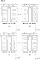
- FIG. 3 schematically illustrates how the direction of the alignment of liquid crystal molecules in each of a pair of liquid crystal elements constituting liquid crystal element group changes through phase modulation.
- FIG.s 3(a) and 3(b) show the phase modulator in a case it is configured with N-type liquid crystal elements.
- X axis is to be set in a direction perpendicular to the drawing sheet
- Y axis is to be set in a direction parallel to the drawing sheet
- Z axis is to be set in a direction along the incident light advancing.
- no drive electric signals are being applied to the liquid crystal elements.
- both of alignment directions of the pair of the liquid crystal elements are aligned along the first alignment direction.
- FIG. 3(b) sufficient drive electric signals are being applied to the liquid crystal elements.
- both of alignment directions of the pair of the liquid crystal elements are respectively aligned along the second alignment direction and the third alignment direction.
- the first alignment direction, the second alignment direction and the third alignment direction are perpendicular with respect to one another. It is to be noted that circles in left side of the liquid crystal element in FIG. 3(b) depicts that the alignment direction of the liquid crystal molecules of this liquid crystal element is perpendicular to the drawing sheet.
- FIG.s 3(c) and 3(d) show the phase modulator in a case it is configured with P-type liquid crystal elements.
- FIG. 3(d) sufficient high drive electric signals are being applied to the liquid crystal elements.
- both of alignment directions of the pair of the liquid crystal elements are aligned along the first alignment direction.
- FIG. 3(c) no drive electric signals are being applied to the liquid crystal elements.
- both of alignment directions of the pair of the liquid crystal elements are respectively aligned along the second alignment direction and the third alignment direction.
- the pair of liquid crystal elements are arranged so that respective planes in which alignment direction of liquid crystal molecules are perpendicular to each other. Namely, in the second liquid crystal element group, an alignment direction of liquid crystal molecules of one of the liquid crystal element can be altered in a plane including the first alignment direction and a fourth alignment direction parallel to the substrate, and an alignment direction of liquid crystal molecules of another of the liquid crystal element can be altered in a plane including the first alignment direction and a fifth alignment direction which is parallel to the substrate and in the same time perpendicular to the fourth alignment direction.
- both of alignment directions of the liquid crystal molecules of left side liquid crystal element are perpendicular to the drawing sheet and both of alignment directions of the liquid crystal molecules of right side liquid crystal element are parallel to the drawing sheet.
- the second alignment direction and the third alignment direction not always have to be respectively perpendicular and parallel to the drawing sheet. They only need to be perpendicular to each other and to be perpendicular to the first alignment direction.
- the fourth alignment direction and the fifth alignment direction not always have to be respectively perpendicular and parallel to the drawing sheet, and they only need to be perpendicular to each other and to be perpendicular to the first alignment direction.
- the second alignment direction may coincide with the fourth alignment direction or with the fifth alignment direction, or not.
- the third alignment direction may coincide with the fifth alignment direction or to the fourth alignment direction, or not. Namely, if it is satisfied that relationship between each of the pair of the liquid crystal elements in each of the first and second liquid crystal element groups, angular relationship between the first and second liquid crystal element groups is not limited, as long as each surface of the substrates is perpendicular to the first alignment direction.
- Each of the pair of liquid crystal elements constituting the first liquid crystal element group may be positioned in series along the incident light advancing direction to each other, or not.
- each of the pair of liquid crystal elements constituting the second liquid crystal element group may be positioned in series along the incident light advancing direction to each other, or not.
- each of the pair of liquid crystal elements constituting the first liquid crystal element group are positioned in series along the incident light advancing direction to each other, they may be positioned in contact with each other.
- each of the pair of liquid crystal elements constituting the second liquid crystal element group are positioned in series along the incident light advancing direction to each other, they may be positioned in contact with each other.
- adhesive may be filled between two liquid crystal elements positioned in contact with each other without air layer.
- contacted two liquid crystal elements may have one substrate between them in common.
- the pair of liquid crystal elements constituting each of the liquid crystal element groups may be built as one integrated liquid crystal element having a centrally located separating layer which exists between each of the pair liquid crystal elements.
- the separating layer is constructed as a double layers each of which having anisotropy perpendicular to each other. In such configuration, it is possible to control alignment directions of the pair of liquid crystal elements of the integrated liquid crystal element by applying single system drive electric signal.
- N-type liquid crystal elements shown in FIG.s 3(a) and 3(b) are used as the pair of liquid crystal elements.
- phase change ⁇ o of the light after passing through the pair of liquid crystal elements can be expressed as in expression (1) described below.
- phase change of the light follows to expression (1).
- each of the liquid crystal molecules of the pair of liquid crystal elements are respectively aligned along the second alignment direction and the third alignment direction.
- the alignment direction of the left side of the liquid crystal element in FIG. 3(b) represents the second alignment direction
- the alignment direction of the right side of the liquid crystal element in FIG. 3(b) represents the third alignment direction.
- X axis is to be set in the second alignment direction
- Y axis is to be set in the third alignment direction.
- the refractive index for the light passing through the pair of liquid crystal elements is n o ( ⁇ )+n e ( ⁇ ), and expression (2) is obtained.
- W 12 e ⁇ i n e ⁇ + n o ⁇ 2 2 ⁇ ⁇ ⁇ d 1 0 0 1
- the pair of liquid crystal elements of respective thickness equal d/2 is behaving like a single liquid crystal element of thickness equal to d and of refractive index equal to the average of refractive indices (n e ( ⁇ ) + n o ( ⁇ ))/2.
- phase change ⁇ e ( ⁇ ) corresponds to the phase change at which a light passes through a liquid crystal element with liquid crystal material whose refractive index (n e ( ⁇ ) +n o ( ⁇ ))/2 is the average of the refractive indices in the direction of X axis and in the direction Y axis and thickness of the liquid crystal material is d.
- phase modulation ⁇ ( ⁇ ), occurring in a liquid crystal element group as changing from the state shown in FIG. 3(a) to the state shown in FIG. 3(b) can be expressed as in expression (4) below.
- phase modulation between two particular states i.e. the respective refractive indices of the pair of liquid crystal elements for the linearly polarization light having any direction of polarization plane passing through in two particular states are n o ( ⁇ ) and n e ( ⁇ ), and intermediate refractive index between these two particular refractive indices of n o ( ⁇ ) and n e ( ⁇ ) also changes in correspondence to the wavelength ⁇ of the incident light similar to the changing of n o ( ⁇ ) and n e ( ⁇ ).
- the alignment direction of liquid crystal molecules of one of the pair of liquid crystal elements is aligned along a direction between the first alignment direction and the second alignment direction and the tilt angle of it with the incident light advancing direction is ⁇
- the alignment direction of liquid crystal molecules of another of the pair of liquid crystal elements is aligned along a direction between the first alignment direction and the third alignment direction and the tilt angle of it with the incident light advancing direction is also ⁇
- both of the effective refractive indices of each of the pair of liquid crystal elements for the light having the wavelength ⁇ are shown as expression (5) below.
- FIG.s 4(a) and 4(b) respectively present schematic graphs showing the relationships between two kinds of refractive indices and wavelength for two types of liquid crystal materials 1 and 2 whose refractive index wavelength dependence characteristics are different from each other.
- the solid line on the lower side represents the ordinary refractive index n o ( ⁇ ) of the liquid crystal material with the alignment direction of the liquid crystal molecules assuming in the first alignment direction
- the solid line on the upper side represents the extraordinary refractive index n e ( ⁇ ) of the liquid crystal material with the liquid crystal molecules assuming in the second or third alignment direction.
- both of the ordinary refractive indices n o ( ⁇ ) and n e ( ⁇ ) of the liquid crystal material 1 change only to relatively small extents even as the wavelength ⁇ changes. This means that the difference between n e ( ⁇ ) and n o ( ⁇ ) does not change greatly even as the wavelength ⁇ changes, either.
- the ordinary refractive indices n o ( ⁇ ) and n e ( ⁇ ) of the liquid crystal material 2 change to greater extents as the wavelength ⁇ changes, compared to the extents of change in the refractive indices of the liquid crystal material 1.
- the extraordinary refractive index n e ( ⁇ ) changes particularly greatly as the wavelength ⁇ changes. Thus, as the wavelength ⁇ increases, the difference between n e ( ⁇ ) and n o ( ⁇ ) decreases to a greater extent.
- the achromatic phase modulator according to one of the embodiment of the present invention is achieved by configuring a phase modulator with at least the first liquid crystal element group composed of a pair of liquid crystal elements with liquid crystal material having the first refractive index wavelength dependence characteristics and the second liquid crystal element group composed of a pair of liquid crystal elements with liquid crystal material having the second refractive index wavelength dependence characteristics.
- the achromatic phase modulator according to the embodiment of the present invention is achieved by configuring a phase modulator with at least four liquid crystal elements.
- thicknesses the liquid crystal layers of each of the pair of liquid crystal elements are substantially the same to each other. Total thickness of the liquid crystal layers of the liquid crystal material 1 is assumed to be d 1 and total thickness of the layers of the liquid crystal material 2 is assumed to be d 2 .
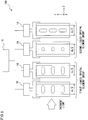
- FIG. 5 shows an achromatic phase modulator 100 configured as described above.
- X axis is to be set in a direction perpendicular to the drawing sheet
- Y axis is to be set in a direction parallel to the drawing sheet
- Z axis is to be set in a direction along the incident light advancing.
- Two sets of liquid crystal element groups the first liquid crystal element group composed of the pair of liquid crystal elements using the liquid crystal material 1 and the second liquid crystal element group composed of the pair of liquid crystal elements using the liquid crystal material 2, are disposed in series in the phase modulator 100.
- Thicknesses of both of the liquid crystal material layers in each of the pair of liquid crystal elements constituting the first liquid crystal element group are d 1 /2 and both of the liquid crystal material layers of each of the pair of liquid crystal elements constituting the second liquid crystal element group are d 2 /2.
- Plurality of power sources 14 are connected to each of the liquid crystal elements so as to provide drive electric signals to be applied to the individual liquid crystal elements.
- the drive electric signals applied from the power sources 14 to the individual liquid crystal elements are controlled by a control device 15. It is to be noted that there are no restrictions whatsoever with regard to the order in which the liquid crystal elements are disposed. In other words, the incident light may enter either of these liquid crystal elements first.
- the alignment direction of liquid crystal molecules therein can be altered between the first alignment direction substantially equal to the direction which the incident light advances and the second alignment direction perpendicular to the first alignment direction, or between the first alignment direction and the third direction perpendicular to both of the first alignment direction and the second alignment direction.
- the changes in the effective refractive indices must occur along opposite directions at the pair of liquid crystal elements constituting the first liquid crystal element group and the pair of liquid crystal elements constituting the second liquid crystal element group.
- the effective refractive index at the pair of liquid crystal elements constituting the second liquid crystal element group needs to decrease if the effective refractive index at the pair of liquid crystal elements constituting the first liquid crystal element group is to increase, whereas the effective refractive index at the pair of liquid crystal elements constituting the second liquid crystal element group needs to increase if the effective refractive index at the pair of liquid crystal elements constituting the first liquid crystal element group is to decrease.
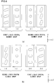
- FIG.s 6(a) and 6(b) show how the liquid crystal molecules may behave in this situation.
- X axis is to be set in a direction perpendicular to the drawing sheet
- Y axis is to be set in a direction parallel to the drawing sheet
- Z axis is to be set in a direction along the incident light advancing.
- the pair of liquid crystal elements constituting the first liquid crystal element group represent in liquid crystal elements 1-1 and 1-2 and the pair of liquid crystal elements constituting the second liquid crystal element group represent in liquid crystal elements 2-1 and 2-2.
- the alignment direction of liquid crystal molecules in the liquid crystal element 1-1 represents a direction slightly displaced from the first alignment direction toward the third alignment direction.
- the alignment direction of liquid crystal molecules in the liquid crystal element 1-2 represents a direction slightly displaced from the first alignment direction toward the second alignment direction. Tilt angles of the liquid crystal molecules in the liquid crystal elements 1-1 and 1-2 with the incident light advancing direction are substantially the same to each other.
- the alignment direction of liquid crystal molecules in the liquid crystal element 2-1 represents a direction slightly displaced from the second alignment direction toward the first alignment direction.
- the alignment direction of liquid crystal molecules in the liquid crystal element 2-2 represents a direction slightly displaced from the third alignment direction toward the first alignment direction. Tilt angles of the liquid crystal molecules in the liquid crystal elements 2-1 and 2-2 with the incident light advancing direction are substantially the same to each other.
- the alignment direction of liquid crystal molecules in the liquid crystal element 1-1 represents a direction slightly displaced from the third alignment direction toward the first alignment direction.
- the alignment direction of liquid crystal molecules in the liquid crystal element 1-2 represents a direction slightly displaced from the second alignment direction toward the first alignment direction. Tilt angles of the liquid crystal molecules in the liquid crystal elements 1-1 and 1-2 with the incident light advancing direction are substantially the same to each other.
- the alignment direction of liquid crystal molecules in the liquid crystal element 2-1 represents a direction slightly displaced from the first alignment direction toward the second alignment direction.
- the alignment direction of liquid crystal molecules in the liquid crystal element 2-2 represents a direction slightly displaced from the first alignment direction toward the third alignment direction. Tilt angles of the liquid crystal molecules in the liquid crystal elements 2-1 and 2-2 with the incident light advancing direction are substantially the same to each other.
- the effective refractive index changes at each of the liquid crystal elements will be explained by referring to FIG.s 4(a) and 4(b) .
- the effective refractive index at the pair of liquid crystal elements constituting the first liquid crystal element group are increased from n 11 ( ⁇ 1 ) to n 12 ( ⁇ 1 ), whereas the effective refractive index at the pair of liquid crystal elements constituting the second liquid crystal element group are decreased from n 21 ( ⁇ 1 ) to n 22 ( ⁇ 1 ).
- These changes in the effective refractive indices are indicated by the arrows marked x 1 and y 1 in FIG.s 4(a) and 4(b) respectively.
- sum of these modulations ⁇ ( ⁇ 1 ) is expressed as;
- This expression indicates that the total thickness d 1 of the liquid crystal material layers having the first refractive index wavelength dependence characteristics and the total thickness d 2 of the liquid crystal material layers having the second refractive index wavelength dependence characteristics can be set so as to satisfy a condition expressed as; x 1 ⁇ x 2 d 1 ⁇ y 2 ⁇ y 1 d 2 Namely, d 1 and d 2 can be set so that (x 1 -x 2 )/(y 2 -y 1 ) ⁇ d 2 /d 1 is satisfied.
- Expression (10) indicates that (x 2 d 1 +y 2 d 2 ) in expression (9) is greater than(x 1 d 1 +y 1 d 2 ) in expression (8).
- the numerator in expression (9) for the phase modulation achieved for light having the greater wavelength ⁇ 2 is greater than the numerator in expression (8) for the phase modulation achieved for light having the smaller wavelength ⁇ 1 .
- x 1 , y 1 , x 2 , y 2 , d 1 and d 2 can be set so as to equalize (x 1 d 1 +y 1 d 2 )/(x 2 d 1 +y 2 d 2 ) to ⁇ 1 / ⁇ 2 .
- x 1 , y 1 , x 2 and y 2 through the choice of the two liquid crystals materials and the two designed wavelengths, d 1 and d 2 can be set (by solving the two equation linear system with two remaining unknown values) so that below expression (11) is satisfied.
- x 1 d 1 + y 1 d 2 / x 2 d 1 + y 2 d 2 ⁇ 1 / ⁇ 2
- ⁇ ( ⁇ 1 ) ⁇ ( ⁇ 2 )
- achromatic phase modulation can be achieved by selecting the optimal values for the thicknesses of the liquid crystal material layers having the first refractive index wavelength dependence characteristics and the second refractive index wavelength dependence characteristics, the optimal refractive index wavelength dependence characteristics to be manifested by these liquid crystal materials and the optimal settings for the changes in the refractive effective indices at the liquid crystal elements.
- the extents of change in the effective refractive indices at the liquid crystal elements may be set by, for instance, controlling the voltages applied to the liquid crystal elements.
- achromatic phase modulation is achieved in conjunction with light at two particular different wavelengths ⁇ 1 and ⁇ 2 in the example described above, achromatic phase modulation may also be achieved in conjunction with a greater number of wavelengths. For instance, achromatic phase modulation for a maximum phase shift level of 2 ⁇ rad may be achieved with the phase modulation error attributable to the varying wavelengths kept down to a value equal to or less than 0.1 ⁇ rad for light with wavelengths over the visible light wavelength range of 400 nm through 700 nm.
- phase modulator configured with a greater number of liquid crystal element groups.
- an achromatic phase modulator configured with three sets of liquid crystal element groups will assure even less error attributable to the varying wavelengths.
- control should be executed for the phase modulation so that the effective refractive indices at two pairs of liquid crystal elements constituting two sets of liquid crystal element groups among the three sets of liquid crystal element groups change in a manner opposite to that with which the effective refractive indices at a pair of liquid crystal elements constituting the remaining one liquid crystal element group change.
- the effective refractive indices at the pairs of liquid crystal elements respectively constituting the two sets of liquid crystal element groups are to increase, the effective refractive indices at the pair of liquid crystal elements constituting the remaining one liquid crystal element group should decrease, whereas if the effective refractive indices at the pairs of liquid crystal elements respectively constituting the two sets of liquid crystal element groups are to decrease, the effective refractive indices at the pair of liquid crystal elements constituting the remaining one liquid crystal element group should increase.
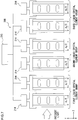
- FIG. 7 shows an example of an achromatic phase modulator 200 composed of six liquid crystal elements of three sets of liquid crystal element groups.
- X axis is to be set in a direction perpendicular to the drawing sheet
- Y axis is to be set in a direction parallel to the drawing sheet
- Z axis is to be set in a direction along the incident light advancing.
- the achromatic phase modulator 200 includes three sets of liquid crystal element groups of liquid crystal elements 1-1, 1-2, 2-1, 2-2, 3-1 and 3-2.
- the power sources 214 are connected to each of these liquid crystal elements for applying voltages to them.
- the voltages applied from the power sources 214 to each of the liquid crystal elements are controlled by the control device 215. It is to be noted that there are no restrictions whatsoever with regard to the order in which these liquid crystal elements are disposed. In other words, the incident light may enter either of these liquid crystal elements first.
- the thicknesses of both of the liquid crystal material layers of the liquid crystal elements 1-1 and 1-2 constituting the first liquid crystal element group are d 1 /2
- the thicknesses of both of the liquid crystal material layers of the liquid crystal elements 2-1 and 2-2 constituting the second liquid crystal element group are d 2 /2
- the thicknesses of both of the liquid crystal material layers of the liquid crystal elements 3-1 and 3-2 constituting the third liquid crystal element group are d 3 /2.
- phase modulation for the wavelength component of ⁇ 1 of incoming light ⁇ ( ⁇ 1 ) achieved via these six liquid crystal elements of three sets of liquid crystal element groups, by altering the effective refractive indices of the liquid crystal materials so that from n 11 ( ⁇ 1 ) to n 12 ( ⁇ 1 ) at the both of liquid crystal elements constituting the first liquid crystal group, from n 21 ( ⁇ 1 ) to n 22 ( ⁇ 1 ) at the both of liquid crystal elements constituting the second liquid crystal group, and from n 31 ( ⁇ 1 ) to n 32 ( ⁇ 1 ) at the both of liquid crystal elements constituting the third liquid crystal group, is expressed as; ⁇ ⁇ ⁇ ⁇ 1 2 ⁇ ⁇ x 1 d 1 + y 1 d 2 + z 1 d 3 / ⁇ 1 x 1 , y 1 and z 1 in the expression above respectively represent n 12 ( ⁇ 1 )-n 11 ( ⁇ 1 ), n 22 ( ⁇ 1 )-n 21 ( ⁇ 1 ) and n 32
- Each refractive index wavelength dependence characteristics of these liquid crystal materials depends on both of the ordinary refractive index n o ( ⁇ ) in the state in which the liquid crystal molecules are aligned along the direction parallel to the light advancing direction, and the extraordinary refractive index n e ( ⁇ ) in the state in which the liquid crystal molecules are aligned along the direction perpendicular to the light advancing direction.
- Such refractive index wavelength dependence characteristics can be described using Cauchy's dispersion formula.
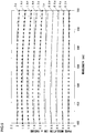
- FIG. 8 presents several examples of the refractive index wavelength dependence characteristics that may be determined as described above in schematic representation.
- values of d 1 and d 2 respectively represent the total thicknesses of the liquid crystal material layers of the liquid crystal elements each respectively constituting the first and the second liquid crystal element groups.
- value of d 1 /2 represents the thickness of the liquid crystal layer of each of the liquid crystal elements constituting the first liquid crystal element group
- value of d 2 /2 represents the thickness of the liquid crystal layer of each of the liquid crystal elements constituting the second liquid crystal element group.
- each combination of two different liquid crystal materials and total thicknesses of the corresponding liquid crystal material layers which satisfy the following conditions, are selected by scrutinizing the plurality of combinations.
- the refractive index wavelength dependence characteristics of these liquid crystal materials are shown in FIG. 8 .
- the total thicknesses d 1 and d 2 of the liquid crystal material layers in this combination of these two liquid crystal materials are calculated to be 28.33 ⁇ m for the MDA-02-2359 and 11.06 ⁇ m for the E7 respectively. Namely, the thicknesses of the liquid crystal layers of each pair of liquid crystal elements constituting the first liquid crystal element group are both 14.165 ⁇ m and the thicknesses of the liquid crystal layers of each pair of liquid crystal elements constituting the second liquid crystal element group are both 5.53 ⁇ m.
- the alignment directions of liquid crystal molecules (MDA-02-2359) of the pair of liquid crystal elements constituting the first liquid crystal element group are respectively in the second alignment direction and the third alignment direction
- the alignment directions of liquid crystal molecules (E7) of the pair of liquid crystal elements constituting the second liquid crystal element group are both in the first alignment direction.
- the control unit applies substantially the same control electric signals to each of the pair of liquid crystal elements constituting in each of the liquid crystal elements. Namely, the control unit applies substantially the same control electric signals to each of the pair of liquid crystal elements constituting the first liquid crystal element group. Similarly, the control unit applies substantially the same control electric signals to each of the pair of liquid crystal elements constituting the second liquid crystal element group.
- the first modulation condition remains the same. Namely, the alignment directions of liquid crystal molecules (MDA-02-2359) of the pair of liquid crystal elements constituting the first liquid crystal element group are both in the first alignment direction, and the alignment directions of liquid crystal molecules (E7) of the pair of liquid crystal elements constituting the second liquid crystal element group are respectively in the second alignment direction and the third alignment direction.
- This first alignment condition is called an initial condition.
- optimal effective refractive indices for the liquid crystal elements constituting the first liquid crystal element group and the liquid crystal elements constituting the second liquid crystal element group can be calculated so as to minimize the phase modulation error for light having wavelengths at both 400nm and 600nm.
- tilt angles of the liquid crystal molecule directions with the incident light advancing direction in pair of the liquid crystal elements constituting each of the liquid crystal element groups are to be identical with each other. Namely, in this time, the refractive indices thereof are identical.
- phase modulation A ⁇ k occurring as the alignment of the liquid crystal molecules, initially sustaining the first modulation condition, changes to the second modulation condition, can be expressed as in the expression (19) below.
- ⁇ 1 and ⁇ 2 are respectively tilt angles of the liquid crystal molecules with the incident light advancing direction in the liquid crystal elements constituting the first and second liquid crystal element groups to the light advancing direction at the second modulation condition.
- the effective refractive index n eff ( ⁇ , ⁇ ) is described by the expression (5).
- the phase modulation error is the absolute difference between 2 ⁇ ( ⁇ n 1 )( ⁇ , ⁇ 1 )d 1 + ⁇ n 2 ( ⁇ , ⁇ 1 )d 2 )/ ⁇ and ⁇ k in expression (18). In practice, repeated calculations are executed to minimize the phase modulation error at the designed wavelengths of 400nm and 600nm.
- the optimization of the effective refractive indices of liquid crystal elements constituting the first liquid crystal element group and the effective refractive indices of liquid crystal elements constituting the second liquid crystal element group is realized through the adjustment of the tilt angles of liquid crystal molecules ⁇ 1 and ⁇ 2 .
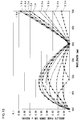
- the calculated absolute phase errors are shown in FIG. 10 . It should be noted that, although the optimization was carried at the wavelengths of 400nm and 600nm, the absolute phase shift errors for the different increments of phase shift modulation do not exceed 0.1 ⁇ rad over the wavelength range from 400nm to 700nm.
- Embodiment 1 three liquid crystal materials among the plurality of liquid crystal materials refractive index dependence characteristics thereof were known.
- the thicknesses of the individual liquid crystal material layers of hypothetical liquid crystal elements composed of these three liquid crystal materials respectively for the liquid crystal elements constituting the first liquid crystal element group, the liquid crystal elements constituting the second liquid crystal element group and the liquid crystal elements constituting the third liquid crystal element group are determined through calculation for a maximum phase modulation of 2 ⁇ .
- Values of d 1 , d 2 and d 3 respectively represent the total thicknesses of the liquid crystal material layers of the liquid crystal elements each constituting the first, second and third liquid crystal element groups. Namely, value of d 1 /2 represents the thickness of the liquid crystal layer of each of the liquid crystal elements constituting the first liquid crystal element group, value of d 2 /2 represents the thickness of the liquid crystal layer of each of the liquid crystal elements constituting the second liquid crystal element group and d 3 /2 represents the thickness of the liquid crystal layer of each of the liquid crystal elements constituting the second liquid crystal element group.
- ⁇ n 1 ( ⁇ ), ⁇ n 2 ( ⁇ ) and ⁇ n 3 ( ⁇ ) all take positive values or negative values in expression (20), the extent of phase modulation decreases as ⁇ becomes greater and under such circumstances, the relationship expressed in (20) cannot be achieved. If one or two among ⁇ n 1 ( ⁇ ), ⁇ n 2 ( ⁇ ) and ⁇ n 3 ( ⁇ ) takes a positive value and the remaining two or one takes a negative value, conditions that allow the relationship expressed in (20) to be true exist, as a concept similar to that described with regard to two different liquid crystal materials in reference to FIG.s 4(a) and 4(b) is applicable.
- each combination of three different liquid crystal materials and the corresponding liquid crystal material layer thicknesses which satisfy the following conditions, are selected by scrutinizing the plurality of combinations.
- the combination of three liquid crystal materials are selected for the phase modulator.
- MDA-02-2359 manufactured by Merck
- MLC-6608 manufactured by Merck
- ZLI-4788 manufactured by Merck
- the refractive index wavelength dependence characteristics of these liquid crystal materials are shown in FIG. 8 .
- These liquid crystal materials all constitute negative dielectric anisotropy (N-type) liquid crystal elements.
- the thicknesses d 1 , d 2 and d 3 of the three liquid crystal material layers in this combination are calculated to be respectively 23.78 ⁇ m for the MDA-02-2359, 14.31 ⁇ m for the MLC-6608 and 18.71 ⁇ m for the ZLI-4788. Namely, the thicknesses of the liquid crystal layers of each pair of liquid crystal elements constituting the first liquid crystal element group are both 11.89 ⁇ m, the thicknesses of the liquid crystal layers of each pair of liquid crystal elements constituting the second liquid crystal element group are both 7.155 ⁇ m and the thicknesses of the liquid crystal layers of each pair of liquid crystal elements constituting the third liquid crystal element group are both 9.355 ⁇ m.
- the directions of effective refractive index changes in the liquid crystal elements both in the first and second liquid crystal element groups are opposite to the direction of effective refractive index change in the liquid crystal elements in the third liquid crystal element group. Namely, in a case the effective refractive indices in both in the first and second liquid crystal element groups are increased, the effective refractive index in the third liquid crystal element group is decreased, or in a case the effective refractive indices in both in the first and second liquid crystal element groups are decreased, the effective refractive index in the third liquid crystal element group is increased.
- all of the alignment directions of the liquid crystal molecules in the liquid crystal elements in both of the first and the second liquid crystal element groups are in the first alignment direction
- the alignment directions of one of the pair of the liquid crystal elements is in the second alignment direction
- the alignment direction of the other of the liquid crystal elements is in the third alignment direction
- phase shift modulation ⁇ k occurring as the alignment of the liquid crystal molecules, initially sustaining the first modulation condition, changes to a second modulation condition, can be expressed as in the expression (24) below.
- ⁇ 1 , ⁇ 2 and ⁇ 3 are respectively tilt angles of the liquid crystal molecules in the liquid crystal elements constituting the first, second and third liquid crystal element groups to the light advancing direction at the second modulation condition.
- the effective refractive index n eff ( ⁇ , ⁇ ) is described by the expression (5). In practice, repeated calculations are executed to minimize the phase shift modulation error at the designed wavelengths of 400nm, 500nm and 660nm. The optimization of the effective refractive indices of liquid crystal elements respectively constituting the first, second and third liquid crystal element groups is realized through the change of the direction of alignment of liquid crystal molecules ⁇ 1 , ⁇ 2 and ⁇ 3 .
- an ITO (indium tin oxide) coating and polyimide coating are applied to a surface of each glass substrate making up a set of glass substrates, so as to form an electrode layer and an alignment layer respectively.
- ITO indium tin oxide
- polyimide polyimide
- homogeneous or homeotropic alignment can be achieved: in the case of homogeneous alignment, the alignment layer can be rubbed along one direction to align the liquid crystal molecules at its vicinity parallel to the glass substrate and following the rubbing direction with a small pre-tilt angle of typically of few degrees. In the case of homeotropic alignment, the alignment layer can be gently rubbed along one direction to align the liquid crystal molecules at its vicinity almost perpendicular to the glass substrate and following a rubbing pre-tilt angle between 85 to 89 degrees.
- the glass substrates are then disposed at fixed positions set apart from each other so as to allow the alignment layers formed thereat to face opposite to each other. If the alignment layers are with homogeneous alignment and have anti-parallel rubbing directions, a liquid crystal material with a positive dielectric anisotropy is injected into the space between the glass substrates to form an anti-parallel aligned electrically controlled birefringence (ECB) liquid crystal cell. If the alignment layers are with homeotropic alignment and have anti-parallel rubbing directions, a liquid crystal material with a negative dielectric anisotropy is injected into the space between the glass substrates to form an vertically aligned (VA) electrically controlled birefringence (ECB) liquid crystal cell.
- VA vertically aligned electrically controlled birefringence
- the gap between the glass substrates is set so that the liquid crystal material layer in the finished liquid crystal element achieves a predetermined thickness.
- the liquid crystal element is manufactured by fixing lead wires to the electrode layers after sealing in the liquid
- a phase measuring setup 500 shown in FIG. 13 is used to measure the phase modulation achieved via a liquid crystal element.
- the phase measuring setup 500 shown in FIG. 9 comprises a laser light source 10 that emits light having a wavelength of 632.8 nm, a first polarizing plate 11 and a second polarizing plate 12 disposed so that the transmission axes thereof extend perpendicular to each other, and a light intensity detector 13.
- the first polarizing plate 11, the second polarizing plate 12 and the light intensity detector 13 are all disposed on the light path of the light emitted from the laser light source 10.
- the liquid crystal element to undergo the phase measurement is positioned between the first polarizing plate 11 and the second polarizing plate 12.
- a power source 14 is connected to the liquid crystal element so as to apply a voltage from the power source 14 to the liquid crystal element, and the voltage applied to the liquid crystal element from the power source 14 is controlled by a control device 15.
- the liquid crystal element is positioned so that when the liquid crystal molecules therein enter the second alignment direction, the direction along which the liquid crystal molecules are aligned forms a 45° angle with the transmission axis of each of the two polarizing plates.
- the light emitted from the laser light source becomes linearly polarized as it is transmitted through the first polarizing plate 11 and the linearly polarized light then enters the liquid crystal elements. While the alignment direction of the liquid crystal molecules in the liquid crystal element sustains the first alignment direction, no birefringence attributable to the liquid crystal material occurs and thus, the polarization direction of the linearly polarized light remains unchanged. This means that the linearly polarized light having been transmitted through the liquid crystal element is not transmitted through the second polarizing plate 12, and for this reason, the intensity of the light detected at the light intensity detector 13 is close to zero.
- the direction along which the liquid crystal molecules are aligned forms a 45° angle relative to the transmission axis of the first polarizing plate 11 and, as a result, birefringence occurs at the liquid crystal material.
- This alters the linearly polarized light to elliptically polarized light (or circularly polarized light), and part of this elliptically polarized light is transmitted through the second polarizing plate 12 and reaches the light intensity detector 13. Consequently, the light intensity detector 13 is able to detect a certain level of light intensity.
- a specific relationship between the voltage V applied to the liquid crystal element and the light intensity I' can be ascertained by measuring the detection target light intensity via the light intensity detector while the control device 15 controls the voltage applied from the power source 14 to the liquid crystal element so as to alter the alignment direction of the liquid crystal molecules from the first alignment direction to the second alignment direction.
- the relationship between the voltage applied to the liquid crystal element and the phase retardation can be determined.
- n eff ( ⁇ ) represents the effective refractive index for light having a wavelength ⁇ in the given alignment direction of the liquid crystal molecules between the light advancing direction and the direction parallel to the substrate of the liquid crystal element. Accordingly, the relationship between the intermediate refractive index n eff ( ⁇ ) at the liquid crystal element and the voltage V applied to the liquid crystal element can be determined by using expressions (25) through (27). The relationship between the intermediate refractive index n eff ( ⁇ ) and the applied voltage V is determined through the procedure described above for each of the liquid crystal elements selected to configure a phase modulator.
- phase modulation quantity via one liquid crystal element group is double of that via one of the pair of the liquid crystal elements in the liquid crystal element group. It is to be noted that applying voltages to the pair of the liquid crystal elements in one liquid crystal element group are substantially the same with each other.
- the values representing the voltage to be applied to each liquid crystal element comprising the phase modulator are determined each in correspondence to a specific extent of phase modulation among varying extents of phase modulation within the range of 0 through 2 ⁇ rad. These voltage values are stored, each in correspondence to a value representing a specific extent of phase modulation, in the form of a voltage application data table into a storage unit (not shown) of the control device.
- FIG. 5 schematically illustrates the achromatic phase modulator 100 as the example of the achromatic phase modulator configured by disposing two sets of liquid crystal element groups.
- Each of the liquid crystal elements constituting the first and second liquid crystal element groups are connected with power sources 14 that provide voltages to be applied to the respective liquid crystal elements.
- a control device 15 controls the voltages to be applied from the power sources 14 to the respective liquid crystal elements. It is to be noted that there are no restrictions whatsoever with respect to the order in which each of the liquid crystal elements are disposed. As incident light sequentially passes through the liquid crystal elements, the phase of the incident light undergoes achromatic phase modulation.
- FIG. 7 schematically illustrates an achromatic phase modulator 200 as the example of the achromatic phase modulator configured by disposing three sets of liquid crystal element groups.
- Each of the liquid crystal elements constituting the first, second and third liquid crystal element groups are connected with power sources 214 that provide voltages to be applied to the respective liquid crystal elements.
- a control device 215 controls the voltages to be applied from the power sources 214 to the respective liquid crystal elements. It is to be noted that there are no restrictions whatsoever with respect to the order in which each of the liquid crystal elements are disposed. As incident light sequentially passes through the three liquid crystal elements, the phase of the incident light undergoes achromatic phase modulation.
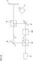
- the phase modulator 100 or 200 is set at a Mach-Zehnder interferometer 600, as shown in FIG. 14 , in order to measure the phase modulation achieved by the phase modulator.
- FIG. 14 shows the phase modulator 100 is set at the Mach-Zehnder interferometer.
- Light emitted from a laser light source 31 enters a beam splitter 32.
- the light exiting the beam splitter 32 travels on two separate light paths L 1 and L 2 .
- the phase modulator 100 is disposed in the light path L 1 .
- the phase of the light transmitted through the phase modulator 100 is modulated in correspondence to the voltages applied to each of the liquid elements therein, the light having undergone the phase modulation is then reflected at a reflecting mirror 33 to enter a beam splitter 35.
- the light advancing through the light path L 2 is reflected at a reflecting mirror 34 and enters the beam splitter 35.
- Light having traveled through the light path L 1 and light having traveled through the light path L 2 become superimposed upon each other at the beam splitter 35.
- the superimposed light is expanded as necessary via a lens and the light is then projected onto a screen S.
- the light exiting the beam splitter 35 which is made up with the light having undergone the phase modulation as it traveled through the light path L 1 and the light having traveled through the light path L 2 without undergoing phase modulation, superimposed upon each other, manifests interference and, as a result, interference fringes appear on the screen S.
- phase modulator 200 when the phase modulator 200 is set at the Mach-Zehnder interferometer, the phase modulator 200 is disposed in the light path L 1 instead of the phase modulator 100, and the phase of the light transmitted through the phase modulator 200 is modulated in correspondence to the voltages applied to each of the liquid elements therein.
- the power sources 14 or 214 (shown in FIG. 5 or FIG. 7 ) are controlled so as to apply voltages to the individual liquid crystal elements as indicated in the voltage application data table stored in the storage unit of the control device 15 (shown in FIG. 5 or FIG. 7 .
- the voltages applied to the individual liquid crystal elements are controlled in correspondence to various target extents of phase modulation, for example, 0 (0 ⁇ rad), 0.5 ⁇ rad, 1 ⁇ rad, 1.5 ⁇ rad and 2 ⁇ rad or the like.
- the move of the interference fringes projected onto the screen S in correspondence to each target phase modulation extent are captured with a CMOS image sensor in a camera C. Then, based upon the shift in the interference fringes having been recorded, the phase modulation that has actually occurred is determined through calculation.
- the voltages applied to the individual liquid crystal elements are controlled in correspondence to the various target extents of phase modulation, for example, 0 ⁇ rad, 0.5 ⁇ rad, 1 ⁇ rad, 1.5 ⁇ rad and 2 ⁇ rad or the like, by using another laser light source 31 that is a He-Ne laser capable of outputting light having a wavelength of 543.5 nm, for example, through a procedure similar to that described above.
- the interference fringes projected onto the screen S in correspondence to each target phase modulation extent are captured with a CMOS image sensor in the camera C and shift occurring in the interference fringes are recorded. Then, based upon the shift in the interference fringes having been recorded, the phase modulation that has actually occurred is determined through calculation.
- FIG. 15 Such an achromatic phase modulator is shown in FIG. 15 .
- X axis is to be set in a direction perpendicular to the drawing sheet
- Y axis is to be set in a direction parallel to the drawing sheet
- Z axis is to be set in a direction along the incident light advancing.
- Two liquid crystal elements may be disposed in contact with one another without air layer. Furthermore, contacted two liquid crystal elements may have one substrate between them in common.
- the pair of liquid crystal elements constituting each of the liquid crystal element groups may be built as one integrated liquid crystal element having a pair of substrates and a separating layer, centrally located between the pair of substrates, separates thereby to each of the pair liquid crystal elements.
- the separating layer is constructed as a double layers each having anisotropy perpendicular to each other.
- X axis is to be set in a direction perpendicular to the drawing sheet
- Y axis is to be set in a direction parallel to the drawing sheet
- Z axis is to be set in a direction along the incident light advancing.
- the thickness of the liquid crystal material layer in each liquid crystal element is determined based upon the maximum extent of change in the refractive index, i.e., the difference between the ordinary refractive index n o ( ⁇ ) in the first alignment direction in which the liquid crystal molecules are aligned along the direction perpendicular to the substrate surfaces and the extraordinary refractive index n e ( ⁇ ) in the second alignment direction in which the liquid crystal molecules are aligned along the direction parallel to the liquid crystal substrate surfaces.
- the present invention is not limited to this example and the thickness of the liquid crystal material layer may instead be determined based upon the difference between the effective refractive indices in any two alignment directions of the liquid crystal molecules between the direction corresponding to the ordinary refractive index n o ( ⁇ ) and the direction corresponding to the extraordinary refractive index n e ( ⁇ ).
- each liquid crystal element is engaged in operation as a whole.
- the present invention is not limited to this example and it may be adopted in conjunction with liquid crystal elements each having a plurality of separate divisional liquid crystal areas arranged in a two-dimensional array.
- a phase modulator adopting such a configuration should be structured by ensuring that the voltages applied to these separate divisional liquid crystal areas can be individually controlled and that the divisional liquid crystal areas in one liquid crystal substrate are set in correspondence to the divisional liquid crystal areas in another liquid crystal substrate.
- FIG. 17 shows an achromatic phase modulator 700 adopting this configuration.
- X axis is to be set in a direction perpendicular to the drawing sheet
- Y axis is to be set in a direction parallel to the drawing sheet
- Z axis is to be set in a direction along the incident light advancing.
- divisional liquid crystal areas formed at one liquid crystal element.
- One of a divisional liquid crystal area 701 formed one of the liquid crystal elements corresponds to divisional liquid crystal areas 702, 703 and 704 formed at other liquid crystal elements so that light propagates between each divisional liquid crystal areas set in correspondence to each other but light does not propagate from one divisional liquid crystal area to other divisional liquid crystal areas they are not in correspondence to each other.
- FIG. 17 does not include illustration of the light sources or the control device.
- achromatic phase modulators are configured with two or three sets of liquid crystal element groups.
- the present invention may be configured with more than three sets of liquid crystal element groups.
Landscapes
- Physics & Mathematics (AREA)
- Nonlinear Science (AREA)
- Chemical & Material Sciences (AREA)
- Crystallography & Structural Chemistry (AREA)
- General Physics & Mathematics (AREA)
- Optics & Photonics (AREA)
- Mathematical Physics (AREA)
- Liquid Crystal (AREA)
- Optical Modulation, Optical Deflection, Nonlinear Optics, Optical Demodulation, Optical Logic Elements (AREA)
Claims (11)
- Achromatischer Phasenmodulator (100), welcher eine Phase eines einfallenden Lichts moduliert und das phasenmodulierte Licht ausgibt, aufweisend:eine Mehrzahl von in Reihe auf einem Lichtpfad des einfallenden Lichts angeordneten Flüssigkristallelementen, die aus Flüssigkristallmaterialien gebildet sind, undeine Steuerungseinheit (15) zum Anlegen von elektrischen Antriebssignalen an die Flüssigkristallelemente, um eine achromatische Phasenmodulation für das einfallende Licht zu erzielen, wobei:die Mehrzahl von Flüssigkristallelementen aufweist: wenigstens eine erste Flüssigkristallelementgruppe, die aus einem Paar von Flüssigkristallelementen gebildet ist, deren jeweilige Flüssigkristallmaterialien eine erste Brechungsindexwellenlängenabhängigkeitscharakteristik aufweisen, und eine zweite Flüssigkristallelementgruppe, die aus einem Paar von Flüssigkristallelementen gebildet ist, deren jeweilige Flüssigkristallmaterialien eine zweite Brechungsindexwellenlängenabhängigkeitscharakteristik aufweisen,Dicken von beiden Flüssigkristallmaterialschichten der Flüssigkristallelemente, die die erste Flüssigkristallelementgruppe bilden, im Wesentlichen einander gleich sind, und Dicken von beiden Flüssigkristallmaterialschichten der Flüssigkristallelemente, die die zweite Flüssigkristallelementgruppe bilden, im Wesentlichen einander gleich sind,durch Ändern von angelegten elektrischen Antriebssignalen an die jeweiligen Flüssigkristallelemente, die die erste Flüssigkristallelementgruppe bilden, eine Ausrichtungsrichtung von Flüssigkristallmolekülen von einem der Flüssigkristallelemente sich in einer Ebene ändert, die aufweist: eine erste Richtung, die im Wesentlichen orthogonal zu einem Substrat (1) ist, und eine zweite Richtung, die orthogonal zu der ersten Richtung ist,eine Ausrichtungsrichtung von Flüssigkristallmolekülen von dem anderen der Flüssigkristallelemente sich in einer Ebene ändert, die aufweist: die erste Richtung und eine dritte Richtung, die orthogonal zu sowohl der ersten Richtung als auch der zweiten Richtung ist, wobei, wenn unpolarisiertes Licht durch das Paar von Flüssigkristallelementen, die die erste Flüssigkristallelementgruppe bilden, hindurchgeht, im Wesentlichen keine Doppelbrechung auftritt,durch Ändern von angelegten elektrischen Antriebssignalen an die jeweiligen Flüssigkristallelemente, die die zweite Flüssigkristallelementgruppe bilden, eine Ausrichtungsrichtung von Flüssigkristallmolekülen von einem der Flüssigkristallelemente sich in einer Ebene ändert, die aufweist: die erste Richtung und eine vierte Richtung, die orthogonal zu der ersten Richtung ist, und eine Ausrichtungsrichtung von Flüssigkristallmolekülen des anderen der Flüssigkristallelemente sich in einer Ebene ändert, die aufweist: die erste Richtung und eine fünfte Richtung, die orthogonal zu sowohl der ersten Richtung als auch der vierten Richtung ist, wobei, wenn unpolarisiertes Licht durch das Paar von Flüssigkristallelementen, die die zweite Flüssigkristallelementgruppe bilden, hindurchgeht, im Wesentlichen keine Doppelbrechung auftritt, unddurch Ändern der angelegten elektrischen Antriebssignale, für Licht, welches eine vorgegebene Wellenlänge aufweist: in einer von der ersten und der zweiten Flüssigkristallelementgruppe ein Mittelwert von Brechungsindizes von dem Paar von Flüssigkristallelementen zunimmt und in der anderen von der ersten und der zweiten Flüssigkristallelementgruppe ein Mittelwert von Brechungsindizes des Paares von Flüssigkristallelementen abnimmt.
- Achromatischer Phasenmodulator nach Anspruch 1, wobei:während das elektrische Antriebssignal nicht an die Flüssigkristallelemente angelegt ist,beide Ausrichtungsrichtungen des Paares von Flüssigkristallmolekülen, die die erste Flüssigkristallelementgruppe bilden, in der ersten Richtung vorliegen, wohingegeneine der Ausrichtungsrichtungen von dem Paar von Flüssigkristallmolekülen, die die zweite Flüssigkristallelementgruppe bilden, in der vierten Richtung vorliegt und die andere der Ausrichtungsrichtungen von dem Paar von Flüssigkristallmolekülen, die die zweite Flüssigkristallelementgruppe bilden, in der fünften Richtung vorliegt.
- Achromatischer Phasenmodulator nach Anspruch 1 oder 2, wobei:
die zweite Richtung identisch zu der vierten Richtung ist und die dritte Richtung identisch zu der fünften Richtung ist. - Achromatischer Phasenmodulator (200) nach Anspruch 1, ferner aufweisend eine dritte Flüssigkristallelementgruppe, die aus einem Paar von Flüssigkristallelementen gebildet ist, deren jeweilige Flüssigkristallmaterialien eine dritte Brechungsindexwellenlängenabhängigkeitscharakteristik aufweisen, wobei
Dicken beider Flüssigkristallmaterialschichten der Flüssigkristallelemente, die die dritte Flüssigkristallelementgruppe bilden, im Wesentlichen einander gleich sind,
durch Ändern von angelegten elektrischen Antriebssignalen an die jeweiligen Flüssigkristallelemente, die die dritte Flüssigkristallelementgruppe bilden eine Ausrichtungsrichtung von Flüssigkristallmolekülen von einem der Flüssigkristallelemente sich in einer Ebene ändert, die aufweist: die erste Richtung und eine sechste Richtung, die orthogonal zu der ersten Richtung ist, und eine Ausrichtungsrichtung von Flüssigkristallmolekülen von dem anderen der Flüssigkristallelemente sich in einer Ebene ändert, die aufweist: die erste Richtung und eine siebte Richtung, die orthogonal zu sowohl der ersten Richtung als auch der sechsten Richtung ist, wobei, wenn unpolarisiertes Licht durch das Paar von Flüssigkristallelementen, die die dritte Flüssigkristallelementgruppe bilden, hindurchgeht, im Wesentlichen keine Doppelbrechung auftritt, und
durch Ändern der angelegten elektrischen Antriebssignale, für eine vorgegebene Wellenlänge aufweisendes Licht:in jeder von zwei von der ersten, zweiten und dritten Flüssigkristallelementgruppe ein Mittelwert von Brechungsindizes des Paares von Flüssigkristallelementen zunimmt und in einer verbleibenden von der ersten, zweiten und dritten Flüssigkristallelementgruppe ein Mittelwert von Brechungsindizes des Paares von Flüssigkristallelementen abnimmt, oderin einer von der ersten, zweiten und dritten Flüssigkristallelementgruppe ein Mittelwert von Brechungsindizes des Paares von Flüssigkristallelementen zunimmt und in jeder von verbleibenden zwei von der ersten, zweiten und dritten Flüssigkristallelementgruppe ein Mittelwert von Brechungsindizes des Paares von Flüssigkristallelementen abnimmt. - Achromatischer Phasenmodulator nach Anspruch 4, wobei: während das elektrische Antriebssignal nicht an die jeweiligen Flüssigkristallelemente angelegt ist,
jede der Ausrichtungsrichtungen des Paares von Flüssigkristallmolekülen, die die erste, zweite und dritte Flüssigkristallelementgruppe bilden, in der ersten Richtung (z) vorliegt. - Achromatischer Phasenmodulator nach Anspruch 4 oder 5, wobei wenigstens zwei der Ausrichtungsrichtungen aus der zweiten Richtung, der vierten Richtung und der sechsten Richtung einander gleich sind und wenigstens zwei der Ausrichtungsrichtungen aus der dritten Richtung, der fünften Richtung und der siebten Richtung einander gleich sind.
- Achromatischer Phasenmodulator nach einem der Ansprüche 1 bis 6, wobei die Steuerungseinheit (15, 215) im Wesentlichen dieselben elektrischen Steuerungssignale an jedes von dem Paar von Flüssigkristallelementen, die die jeweiligen Flüssigkristallelemente bilden, anlegt.
- Achromatischer Phasenmodulator nach einem der Ansprüche 1 bis 7, wobei:das einfallende Licht eine Wellenlänge innerhalb eines sichtbaren Bereichs aufweist unddie Flüssigkristallelemente alle nematische Flüssigkristallelemente sind.
- Achromatischer Phasenmodulator nach einem der Ansprüche 1 bis 8, wobei: in wenigstens einer der Flüssigkristallelementgruppen das Paar von Flüssigkristallelementen, die die korrespondierende Gruppe bilden, in Kontakt zueinander positioniert sind.
- Achromatischer Phasenmodulator nach einem der Ansprüche 1 bis 9, wobei:
in wenigstens einer der Flüssigkristallelementgruppen das Paar von Flüssigkristallelementen, die die korrespondierende Gruppe bilden, ein integriertes Flüssigkristallelement bildet, welches aufweist: ein Paar von Substraten und eine Schicht, die sich mittig zwischen dem Paar von Substraten befindet, wodurch sie das Paar von Flüssigkristallelementen trennt. - Achromatischer Phasenmodulator (700) nach einem der Ansprüche 1 bis 10, wobei:die Flüssigkristallelemente jeweils in eine Mehrzahl von getrennten Teilflüssigkristallbereichen (701, 702, 703, 704) unterteilt sind, die in einem zweidimensionalen Feld angeordnet sind,die Teilflüssigkristallbereiche, die an einem Flüssigkristallelement angeordnet sind, jeweils den Teilflüssigkristallbereichen an einem anderen Flüssigkristallelement zugewandt sind, unddie Steuerungseinheit eine Steuerung derart durchführt, dass sie ein elektrisches Antriebssignal einzeln an jeden der Teilflüssigkristallbereiche (701, 702, 703, 704) anlegt.
Applications Claiming Priority (1)
| Application Number | Priority Date | Filing Date | Title |
|---|---|---|---|
| PCT/JP2015/051154 WO2016111019A1 (en) | 2015-01-09 | 2015-01-09 | Liquid-crystal achromatic phase modulator |
Publications (2)
| Publication Number | Publication Date |
|---|---|
| EP3243103A1 EP3243103A1 (de) | 2017-11-15 |
| EP3243103B1 true EP3243103B1 (de) | 2020-04-29 |
Family
ID=52432888
Family Applications (1)
| Application Number | Title | Priority Date | Filing Date |
|---|---|---|---|
| EP15701593.4A Active EP3243103B1 (de) | 2015-01-09 | 2015-01-09 | Achromatischer phasenmodulator, beruhend auf flüssigkristallen |
Country Status (5)
| Country | Link |
|---|---|
| US (1) | US10598999B2 (de) |
| EP (1) | EP3243103B1 (de) |
| JP (1) | JP6494767B2 (de) |
| CN (1) | CN107430309B (de) |
| WO (1) | WO2016111019A1 (de) |
Families Citing this family (12)
| Publication number | Priority date | Publication date | Assignee | Title |
|---|---|---|---|---|
| JP6817623B2 (ja) * | 2016-11-28 | 2021-01-20 | 公立大学法人兵庫県立大学 | 偏光制御装置および偏光制御方法 |
| IL300301B2 (en) | 2017-06-12 | 2024-08-01 | Magic Leap Inc | Augmented reality display with multi-component adaptive lenses to change plane depths |
| JP2019074545A (ja) * | 2017-10-12 | 2019-05-16 | キヤノン株式会社 | 光学素子および光学機器 |
| WO2019100020A1 (en) * | 2017-11-17 | 2019-05-23 | Sharp Gary D | Self-compensating liquid crystal retardation switch |
| US10564504B2 (en) * | 2017-11-30 | 2020-02-18 | Palo Alto Research Center Incorporated | Liquid-crystal variable retarder using liquid crystal cells of differing thicknesses |
| US10663346B2 (en) | 2017-12-29 | 2020-05-26 | Palo Alto Research Center Incorporated | Method and apparatus for transforming uniformly or non-uniformly sampled interferograms to produce spectral data |
| US10983338B2 (en) | 2017-12-29 | 2021-04-20 | Palo Alto Research Center Incorporated | Exit-pupil expander used distribute light over a liquid-crystal variable retarder |
| CN114270228A (zh) | 2019-05-24 | 2022-04-01 | 奇跃公司 | 可变焦组件 |
| WO2021039900A1 (ja) * | 2019-08-28 | 2021-03-04 | 公立大学法人兵庫県立大学 | 試料測定装置および試料測定方法 |
| WO2022032198A1 (en) | 2020-08-07 | 2022-02-10 | Magic Leap, Inc. | Tunable cylindrical lenses and head-mounted display including the same |
| JP2024514416A (ja) * | 2021-03-15 | 2024-04-02 | マジック リープ, インコーポレイテッド | 調整可能円柱レンズを採用する光学デバイスおよび頭部搭載型ディスプレイ |
| US11815746B1 (en) * | 2021-09-30 | 2023-11-14 | Amazon Technologies, Inc. | Method and apparatus for astigmatic correction in electronically tunable prescription glasses |
Family Cites Families (9)
| Publication number | Priority date | Publication date | Assignee | Title |
|---|---|---|---|---|
| JPH02183219A (ja) * | 1989-01-10 | 1990-07-17 | Fujitsu Ltd | カラー液晶パネル |
| JP2870860B2 (ja) * | 1989-09-29 | 1999-03-17 | カシオ計算機株式会社 | 液晶表示素子 |
| US5347382A (en) * | 1992-04-23 | 1994-09-13 | Rumbaugh Scott H | Liquid crystal cell retarder with driving beyond retardance value and two cells for high speed |
| DE4434921C2 (de) * | 1994-09-29 | 1996-12-12 | Wissenschaftlich Tech Optikzen | Achromatisches Phasenverzögerungselement |
| JP4382317B2 (ja) * | 2001-12-06 | 2009-12-09 | シチズンホールディングス株式会社 | 液晶可変波長フィルタ装置 |
| JP2004317714A (ja) * | 2003-04-15 | 2004-11-11 | Sharp Corp | 液晶表示装置および積層位相差板 |
| JP5176194B2 (ja) * | 2006-04-18 | 2013-04-03 | Nltテクノロジー株式会社 | 液晶表示装置及び画像表示システム |
| JP2009014778A (ja) | 2007-06-29 | 2009-01-22 | Nippon Hoso Kyokai <Nhk> | 透過型空間光変調素子およびこれを搭載した光学装置 |
| US8184215B2 (en) * | 2010-08-17 | 2012-05-22 | Lc-Tec Displays Ab | High-speed liquid crystal polarization modulator |
-
2015
- 2015-01-09 JP JP2017536594A patent/JP6494767B2/ja active Active
- 2015-01-09 US US15/542,073 patent/US10598999B2/en active Active
- 2015-01-09 EP EP15701593.4A patent/EP3243103B1/de active Active
- 2015-01-09 WO PCT/JP2015/051154 patent/WO2016111019A1/en active Application Filing
- 2015-01-09 CN CN201580077572.2A patent/CN107430309B/zh active Active
Non-Patent Citations (1)
| Title |
|---|
| None * |
Also Published As
| Publication number | Publication date |
|---|---|
| JP2018501524A (ja) | 2018-01-18 |
| US10598999B2 (en) | 2020-03-24 |
| US20180088381A1 (en) | 2018-03-29 |
| CN107430309B (zh) | 2020-11-06 |
| JP6494767B2 (ja) | 2019-04-03 |
| WO2016111019A1 (en) | 2016-07-14 |
| EP3243103A1 (de) | 2017-11-15 |
| CN107430309A (zh) | 2017-12-01 |
Similar Documents
| Publication | Publication Date | Title |
|---|---|---|
| EP3243103B1 (de) | Achromatischer phasenmodulator, beruhend auf flüssigkristallen | |
| EP3126904B1 (de) | Achromatischer phasenmodulator und optisches gerät | |
| US20190025644A1 (en) | Display panel and display device | |
| EP1370900B1 (de) | Faseroptischer abschwächer | |
| KR102509521B1 (ko) | 광 변조기의 인접하게 배치된 픽셀과 상호 작용하는 광 빔을 결합하기 위한 장치 | |
| JP4080245B2 (ja) | 液晶表示装置 | |
| US7532283B2 (en) | Liquid crystal display | |
| KR102271626B1 (ko) | 액정 표시 장치 | |
| GB2314640A (en) | Liquid crystal devices | |
| US20200209691A1 (en) | Photo-alignment apparatus that realizes desirable distribution through single exposure and method of manufacturing an optical element | |
| US20190310501A1 (en) | Liquid crystal display device | |
| KR20090052297A (ko) | 액정 장치, 프로젝터 및 액정 장치의 광학 보상 방법 | |
| JP2010517105A (ja) | 位相変調光変調器及び位相変調光変調器における振幅変調を最小限に抑える方法 | |
| US10761383B2 (en) | Phase modulator and optical device | |
| US8797497B2 (en) | Phase modulator containing a liquid crystal having a helical structure | |
| JP4543747B2 (ja) | 画像表示装置 | |
| CN113064291A (zh) | 一种提高相位调制量的方法及设备 | |
| US6587172B1 (en) | Controlled angle retarder with liquid crystal cell bias tuned for a sequence of wavelengths | |
| JP3875116B2 (ja) | 複屈折体の複屈折率の波長分散の測定方法、プログラム及び記録媒体 | |
| Yousefzadeh et al. | 31‐3: Continuous High‐Efficiency Beam Deflector for AR/VR Devices | |
| Bhowmick | Continuously Tunable Large Aperture Liquid Crystal Based Lens for De-Focus and Astigmatism Correction | |
| JP3599176B2 (ja) | 液晶表示装置 | |
| KR20000026837A (ko) | 멀티도메인 액정표시소자 | |
| JP2009025354A (ja) | 液晶表示パネルおよび液晶表示装置 | |
| Bagwell et al. | Multi-spectral foveated imaging system |
Legal Events
| Date | Code | Title | Description |
|---|---|---|---|
| STAA | Information on the status of an ep patent application or granted ep patent |
Free format text: STATUS: THE INTERNATIONAL PUBLICATION HAS BEEN MADE |
|
| PUAI | Public reference made under article 153(3) epc to a published international application that has entered the european phase |
Free format text: ORIGINAL CODE: 0009012 |
|
| STAA | Information on the status of an ep patent application or granted ep patent |
Free format text: STATUS: REQUEST FOR EXAMINATION WAS MADE |
|
| 17P | Request for examination filed |
Effective date: 20170705 |
|
| AK | Designated contracting states |
Kind code of ref document: A1 Designated state(s): AL AT BE BG CH CY CZ DE DK EE ES FI FR GB GR HR HU IE IS IT LI LT LU LV MC MK MT NL NO PL PT RO RS SE SI SK SM TR |
|
| AX | Request for extension of the european patent |
Extension state: BA ME |
|
| RAP1 | Party data changed (applicant data changed or rights of an application transferred) |
Owner name: NIKON CORPORATION Owner name: ESSILOR INTERNATIONAL |
|
| DAX | Request for extension of the european patent (deleted) | ||
| STAA | Information on the status of an ep patent application or granted ep patent |
Free format text: STATUS: EXAMINATION IS IN PROGRESS |
|
| 17Q | First examination report despatched |
Effective date: 20190128 |
|
| GRAP | Despatch of communication of intention to grant a patent |
Free format text: ORIGINAL CODE: EPIDOSNIGR1 |
|
| STAA | Information on the status of an ep patent application or granted ep patent |
Free format text: STATUS: GRANT OF PATENT IS INTENDED |
|
| INTG | Intention to grant announced |
Effective date: 20200130 |
|
| GRAS | Grant fee paid |
Free format text: ORIGINAL CODE: EPIDOSNIGR3 |
|
| GRAA | (expected) grant |
Free format text: ORIGINAL CODE: 0009210 |
|
| STAA | Information on the status of an ep patent application or granted ep patent |
Free format text: STATUS: THE PATENT HAS BEEN GRANTED |
|
| AK | Designated contracting states |
Kind code of ref document: B1 Designated state(s): AL AT BE BG CH CY CZ DE DK EE ES FI FR GB GR HR HU IE IS IT LI LT LU LV MC MK MT NL NO PL PT RO RS SE SI SK SM TR |
|
| REG | Reference to a national code |
Ref country code: GB Ref legal event code: FG4D |
|
| REG | Reference to a national code |
Ref country code: CH Ref legal event code: EP |
|
| REG | Reference to a national code |
Ref country code: DE Ref legal event code: R096 Ref document number: 602015051556 Country of ref document: DE |
|
| REG | Reference to a national code |
Ref country code: AT Ref legal event code: REF Ref document number: 1264204 Country of ref document: AT Kind code of ref document: T Effective date: 20200515 |
|
| REG | Reference to a national code |
Ref country code: IE Ref legal event code: FG4D |
|
| REG | Reference to a national code |
Ref country code: NL Ref legal event code: MP Effective date: 20200429 |
|
| REG | Reference to a national code |
Ref country code: LT Ref legal event code: MG4D |
|
| PG25 | Lapsed in a contracting state [announced via postgrant information from national office to epo] |
Ref country code: FI Free format text: LAPSE BECAUSE OF FAILURE TO SUBMIT A TRANSLATION OF THE DESCRIPTION OR TO PAY THE FEE WITHIN THE PRESCRIBED TIME-LIMIT Effective date: 20200429 Ref country code: SE Free format text: LAPSE BECAUSE OF FAILURE TO SUBMIT A TRANSLATION OF THE DESCRIPTION OR TO PAY THE FEE WITHIN THE PRESCRIBED TIME-LIMIT Effective date: 20200429 Ref country code: IS Free format text: LAPSE BECAUSE OF FAILURE TO SUBMIT A TRANSLATION OF THE DESCRIPTION OR TO PAY THE FEE WITHIN THE PRESCRIBED TIME-LIMIT Effective date: 20200829 Ref country code: NO Free format text: LAPSE BECAUSE OF FAILURE TO SUBMIT A TRANSLATION OF THE DESCRIPTION OR TO PAY THE FEE WITHIN THE PRESCRIBED TIME-LIMIT Effective date: 20200729 Ref country code: LT Free format text: LAPSE BECAUSE OF FAILURE TO SUBMIT A TRANSLATION OF THE DESCRIPTION OR TO PAY THE FEE WITHIN THE PRESCRIBED TIME-LIMIT Effective date: 20200429 Ref country code: GR Free format text: LAPSE BECAUSE OF FAILURE TO SUBMIT A TRANSLATION OF THE DESCRIPTION OR TO PAY THE FEE WITHIN THE PRESCRIBED TIME-LIMIT Effective date: 20200730 Ref country code: PT Free format text: LAPSE BECAUSE OF FAILURE TO SUBMIT A TRANSLATION OF THE DESCRIPTION OR TO PAY THE FEE WITHIN THE PRESCRIBED TIME-LIMIT Effective date: 20200831 |
|
| REG | Reference to a national code |
Ref country code: AT Ref legal event code: MK05 Ref document number: 1264204 Country of ref document: AT Kind code of ref document: T Effective date: 20200429 |
|
| PG25 | Lapsed in a contracting state [announced via postgrant information from national office to epo] |
Ref country code: BG Free format text: LAPSE BECAUSE OF FAILURE TO SUBMIT A TRANSLATION OF THE DESCRIPTION OR TO PAY THE FEE WITHIN THE PRESCRIBED TIME-LIMIT Effective date: 20200729 Ref country code: LV Free format text: LAPSE BECAUSE OF FAILURE TO SUBMIT A TRANSLATION OF THE DESCRIPTION OR TO PAY THE FEE WITHIN THE PRESCRIBED TIME-LIMIT Effective date: 20200429 Ref country code: HR Free format text: LAPSE BECAUSE OF FAILURE TO SUBMIT A TRANSLATION OF THE DESCRIPTION OR TO PAY THE FEE WITHIN THE PRESCRIBED TIME-LIMIT Effective date: 20200429 Ref country code: RS Free format text: LAPSE BECAUSE OF FAILURE TO SUBMIT A TRANSLATION OF THE DESCRIPTION OR TO PAY THE FEE WITHIN THE PRESCRIBED TIME-LIMIT Effective date: 20200429 |
|
| PG25 | Lapsed in a contracting state [announced via postgrant information from national office to epo] |
Ref country code: NL Free format text: LAPSE BECAUSE OF FAILURE TO SUBMIT A TRANSLATION OF THE DESCRIPTION OR TO PAY THE FEE WITHIN THE PRESCRIBED TIME-LIMIT Effective date: 20200429 Ref country code: AL Free format text: LAPSE BECAUSE OF FAILURE TO SUBMIT A TRANSLATION OF THE DESCRIPTION OR TO PAY THE FEE WITHIN THE PRESCRIBED TIME-LIMIT Effective date: 20200429 |
|
| PG25 | Lapsed in a contracting state [announced via postgrant information from national office to epo] |
Ref country code: DK Free format text: LAPSE BECAUSE OF FAILURE TO SUBMIT A TRANSLATION OF THE DESCRIPTION OR TO PAY THE FEE WITHIN THE PRESCRIBED TIME-LIMIT Effective date: 20200429 Ref country code: IT Free format text: LAPSE BECAUSE OF FAILURE TO SUBMIT A TRANSLATION OF THE DESCRIPTION OR TO PAY THE FEE WITHIN THE PRESCRIBED TIME-LIMIT Effective date: 20200429 Ref country code: AT Free format text: LAPSE BECAUSE OF FAILURE TO SUBMIT A TRANSLATION OF THE DESCRIPTION OR TO PAY THE FEE WITHIN THE PRESCRIBED TIME-LIMIT Effective date: 20200429 Ref country code: ES Free format text: LAPSE BECAUSE OF FAILURE TO SUBMIT A TRANSLATION OF THE DESCRIPTION OR TO PAY THE FEE WITHIN THE PRESCRIBED TIME-LIMIT Effective date: 20200429 Ref country code: CZ Free format text: LAPSE BECAUSE OF FAILURE TO SUBMIT A TRANSLATION OF THE DESCRIPTION OR TO PAY THE FEE WITHIN THE PRESCRIBED TIME-LIMIT Effective date: 20200429 Ref country code: RO Free format text: LAPSE BECAUSE OF FAILURE TO SUBMIT A TRANSLATION OF THE DESCRIPTION OR TO PAY THE FEE WITHIN THE PRESCRIBED TIME-LIMIT Effective date: 20200429 Ref country code: SM Free format text: LAPSE BECAUSE OF FAILURE TO SUBMIT A TRANSLATION OF THE DESCRIPTION OR TO PAY THE FEE WITHIN THE PRESCRIBED TIME-LIMIT Effective date: 20200429 Ref country code: EE Free format text: LAPSE BECAUSE OF FAILURE TO SUBMIT A TRANSLATION OF THE DESCRIPTION OR TO PAY THE FEE WITHIN THE PRESCRIBED TIME-LIMIT Effective date: 20200429 |
|
| REG | Reference to a national code |
Ref country code: DE Ref legal event code: R097 Ref document number: 602015051556 Country of ref document: DE |
|
| PG25 | Lapsed in a contracting state [announced via postgrant information from national office to epo] |
Ref country code: PL Free format text: LAPSE BECAUSE OF FAILURE TO SUBMIT A TRANSLATION OF THE DESCRIPTION OR TO PAY THE FEE WITHIN THE PRESCRIBED TIME-LIMIT Effective date: 20200429 Ref country code: SK Free format text: LAPSE BECAUSE OF FAILURE TO SUBMIT A TRANSLATION OF THE DESCRIPTION OR TO PAY THE FEE WITHIN THE PRESCRIBED TIME-LIMIT Effective date: 20200429 |
|
| PLBE | No opposition filed within time limit |
Free format text: ORIGINAL CODE: 0009261 |
|
| STAA | Information on the status of an ep patent application or granted ep patent |
Free format text: STATUS: NO OPPOSITION FILED WITHIN TIME LIMIT |
|
| 26N | No opposition filed |
Effective date: 20210201 |
|
| PG25 | Lapsed in a contracting state [announced via postgrant information from national office to epo] |
Ref country code: SI Free format text: LAPSE BECAUSE OF FAILURE TO SUBMIT A TRANSLATION OF THE DESCRIPTION OR TO PAY THE FEE WITHIN THE PRESCRIBED TIME-LIMIT Effective date: 20200429 |
|
| PG25 | Lapsed in a contracting state [announced via postgrant information from national office to epo] |
Ref country code: MC Free format text: LAPSE BECAUSE OF FAILURE TO SUBMIT A TRANSLATION OF THE DESCRIPTION OR TO PAY THE FEE WITHIN THE PRESCRIBED TIME-LIMIT Effective date: 20200429 |
|
| REG | Reference to a national code |
Ref country code: CH Ref legal event code: PL |
|
| PG25 | Lapsed in a contracting state [announced via postgrant information from national office to epo] |
Ref country code: LU Free format text: LAPSE BECAUSE OF NON-PAYMENT OF DUE FEES Effective date: 20210109 |
|
| REG | Reference to a national code |
Ref country code: BE Ref legal event code: MM Effective date: 20210131 |
|
| PG25 | Lapsed in a contracting state [announced via postgrant information from national office to epo] |
Ref country code: LI Free format text: LAPSE BECAUSE OF NON-PAYMENT OF DUE FEES Effective date: 20210131 Ref country code: CH Free format text: LAPSE BECAUSE OF NON-PAYMENT OF DUE FEES Effective date: 20210131 |
|
| PG25 | Lapsed in a contracting state [announced via postgrant information from national office to epo] |
Ref country code: IE Free format text: LAPSE BECAUSE OF NON-PAYMENT OF DUE FEES Effective date: 20210109 |
|
| PG25 | Lapsed in a contracting state [announced via postgrant information from national office to epo] |
Ref country code: BE Free format text: LAPSE BECAUSE OF NON-PAYMENT OF DUE FEES Effective date: 20210131 |
|
| PG25 | Lapsed in a contracting state [announced via postgrant information from national office to epo] |
Ref country code: HU Free format text: LAPSE BECAUSE OF FAILURE TO SUBMIT A TRANSLATION OF THE DESCRIPTION OR TO PAY THE FEE WITHIN THE PRESCRIBED TIME-LIMIT; INVALID AB INITIO Effective date: 20150109 |
|
| PG25 | Lapsed in a contracting state [announced via postgrant information from national office to epo] |
Ref country code: CY Free format text: LAPSE BECAUSE OF FAILURE TO SUBMIT A TRANSLATION OF THE DESCRIPTION OR TO PAY THE FEE WITHIN THE PRESCRIBED TIME-LIMIT Effective date: 20200429 |
|
| P01 | Opt-out of the competence of the unified patent court (upc) registered |
Effective date: 20230728 |
|
| PG25 | Lapsed in a contracting state [announced via postgrant information from national office to epo] |
Ref country code: MK Free format text: LAPSE BECAUSE OF FAILURE TO SUBMIT A TRANSLATION OF THE DESCRIPTION OR TO PAY THE FEE WITHIN THE PRESCRIBED TIME-LIMIT Effective date: 20200429 |
|
| PGFP | Annual fee paid to national office [announced via postgrant information from national office to epo] |
Ref country code: DE Payment date: 20240119 Year of fee payment: 10 Ref country code: GB Payment date: 20240119 Year of fee payment: 10 |
|
| PGFP | Annual fee paid to national office [announced via postgrant information from national office to epo] |
Ref country code: FR Payment date: 20240124 Year of fee payment: 10 |