EP3242826B1 - Fertigungsverfahren für eine modulare lenksäule mit strangpressprofilen - Google Patents
Fertigungsverfahren für eine modulare lenksäule mit strangpressprofilen Download PDFInfo
- Publication number
- EP3242826B1 EP3242826B1 EP15771896.6A EP15771896A EP3242826B1 EP 3242826 B1 EP3242826 B1 EP 3242826B1 EP 15771896 A EP15771896 A EP 15771896A EP 3242826 B1 EP3242826 B1 EP 3242826B1
- Authority
- EP
- European Patent Office
- Prior art keywords
- steering column
- column tube
- blank
- jacket tube
- tube
- Prior art date
- Legal status (The legal status is an assumption and is not a legal conclusion. Google has not performed a legal analysis and makes no representation as to the accuracy of the status listed.)
- Active
Links
Images

Classifications
-
- B—PERFORMING OPERATIONS; TRANSPORTING
- B62—LAND VEHICLES FOR TRAVELLING OTHERWISE THAN ON RAILS
- B62D—MOTOR VEHICLES; TRAILERS
- B62D1/00—Steering controls, i.e. means for initiating a change of direction of the vehicle
- B62D1/02—Steering controls, i.e. means for initiating a change of direction of the vehicle vehicle-mounted
- B62D1/16—Steering columns
- B62D1/18—Steering columns yieldable or adjustable, e.g. tiltable
- B62D1/185—Steering columns yieldable or adjustable, e.g. tiltable adjustable by axial displacement, e.g. telescopically
-
- B—PERFORMING OPERATIONS; TRANSPORTING
- B23—MACHINE TOOLS; METAL-WORKING NOT OTHERWISE PROVIDED FOR
- B23P—METAL-WORKING NOT OTHERWISE PROVIDED FOR; COMBINED OPERATIONS; UNIVERSAL MACHINE TOOLS
- B23P15/00—Making specific metal objects by operations not covered by a single other subclass or a group in this subclass
-
- B—PERFORMING OPERATIONS; TRANSPORTING
- B62—LAND VEHICLES FOR TRAVELLING OTHERWISE THAN ON RAILS
- B62D—MOTOR VEHICLES; TRAILERS
- B62D1/00—Steering controls, i.e. means for initiating a change of direction of the vehicle
- B62D1/02—Steering controls, i.e. means for initiating a change of direction of the vehicle vehicle-mounted
- B62D1/16—Steering columns
-
- B—PERFORMING OPERATIONS; TRANSPORTING
- B62—LAND VEHICLES FOR TRAVELLING OTHERWISE THAN ON RAILS
- B62D—MOTOR VEHICLES; TRAILERS
- B62D1/00—Steering controls, i.e. means for initiating a change of direction of the vehicle
- B62D1/02—Steering controls, i.e. means for initiating a change of direction of the vehicle vehicle-mounted
- B62D1/16—Steering columns
- B62D1/18—Steering columns yieldable or adjustable, e.g. tiltable
-
- B—PERFORMING OPERATIONS; TRANSPORTING
- B62—LAND VEHICLES FOR TRAVELLING OTHERWISE THAN ON RAILS
- B62D—MOTOR VEHICLES; TRAILERS
- B62D1/00—Steering controls, i.e. means for initiating a change of direction of the vehicle
- B62D1/02—Steering controls, i.e. means for initiating a change of direction of the vehicle vehicle-mounted
- B62D1/16—Steering columns
- B62D1/18—Steering columns yieldable or adjustable, e.g. tiltable
- B62D1/184—Mechanisms for locking columns at selected positions
-
- B—PERFORMING OPERATIONS; TRANSPORTING
- B21—MECHANICAL METAL-WORKING WITHOUT ESSENTIALLY REMOVING MATERIAL; PUNCHING METAL
- B21C—MANUFACTURE OF METAL SHEETS, WIRE, RODS, TUBES, PROFILES OR LIKE SEMI-MANUFACTURED PRODUCTS OTHERWISE THAN BY ROLLING; AUXILIARY OPERATIONS USED IN CONNECTION WITH METAL-WORKING WITHOUT ESSENTIALLY REMOVING MATERIAL
- B21C23/00—Extruding metal; Impact extrusion
- B21C23/02—Making uncoated products
-
- B—PERFORMING OPERATIONS; TRANSPORTING
- B23—MACHINE TOOLS; METAL-WORKING NOT OTHERWISE PROVIDED FOR
- B23P—METAL-WORKING NOT OTHERWISE PROVIDED FOR; COMBINED OPERATIONS; UNIVERSAL MACHINE TOOLS
- B23P2700/00—Indexing scheme relating to the articles being treated, e.g. manufactured, repaired, assembled, connected or other operations covered in the subgroups
- B23P2700/50—Other automobile vehicle parts, i.e. manufactured in assembly lines
Definitions
- the present invention relates to a method for manufacturing a steering column with the features of the preamble of claim 1.
- Steering columns have many functions in motor vehicles. On the one hand, they are used to attach the steering wheel and to support the steering shaft or steering shaft on the bodywork. They also serve for attachment of attachments such. B. an anti-theft device or controls. In part, the steering columns are mechanically or electrically adjustable in the axial direction and vertical direction to adjust the position of the steering wheel to the requirements of the driver can. Finally, steering columns should also yield to an obstacle in the event of a collision of the vehicle in order to absorb impact energy of the driver on the steering wheel and thereby reduce the risk of injury to the driver. With all these requirements is also required that steering columns require a small space, have a low weight and play without play and noise.
- Extruded profiles have the advantage of lower production costs compared to die-cast components.
- the document FR 3004154 shows a jacket unit for a steering column, wherein the shell unit is made of an extruded profile.
- the various required functional sections are, for example, attachment areas, Guides for the adjustment function, bearing seats and attachment points for additional components.
- the WO 2008/086548 A1 discloses the preamble of independent claims 1 and 13.
- This object is achieved by a method having the features of claim 1.
- Advantageous developments emerge from the subclaims.
- the object is achieved by a steering column with the features of claim 14.
- Cutting operations are mechanical cutting processes with geometrically defined and geometrically indefinite cutting edges, for example drilling, milling, grinding and turning.
- the cutting can be done in various ways, such as sawing, laser cutting or water jet cutting.
- the outer jacket tube integrally surrounds the steering shaft by more than 270 °. In this way, an optimal support of the steering shaft can be achieved in the outer jacket tube.
- the outer jacket tube encloses the steering shaft by more than 300 °, whereby the steering column undergoes a further improvement of the support and thus a high rigidity of the support can be ensured.
- only recesses preferably in the form of openings, and possibly additionally planar surfaces are introduced by means of machining in the extrusion blank to form the outer jacket tube.
- Breakthroughs are, for example, slots or circular cylindrical holes or threaded holes. Preference is given to the extruded profile for the formation of the outer jacket tube only holes or slots, and plane surfaces introduced by post-processing.
- the recess preferably serve as functional elements, for example for the formation of Verstelllanglöchern and / or holes for passing the clamping axis or for receiving further components.
- Flat surfaces may be provided especially in the areas of the outer shell, which are provided as contact surfaces for mating with other components. Through these flat surfaces a good pairing is favored.
- the cross-sectional area of the blank for forming the outer and / or jacket tube by means of the cutting operation is a maximum of 30% is reduced.
- the cross-sectional area is always the profile cross-sectional area to understand, which is aligned orthogonal to the longitudinal axis.
- the cross-sectional areas are reduced at any length by the cutting operation by a maximum of 30% compared to the unprocessed cross-sectional area of the blank. In this way, a cost-effective production of the outer and / or inner jacket tube can be ensured.
- the cross-sectional area of the blank for forming the outer and / or jacket tube is preferably reduced by a maximum of 20%, particularly preferably 10% and most preferably by 5% by means of the cutting operation.
- the completion comprises the installation of the steering shaft.
- the steering shaft is preferably a particular two-piece and telescopic steering shaft, which comprises at one end a coupling portion for connecting a steering wheel.
- the completion comprises the attachment of a console.
- the mounting of the console may include the assembly of the tensioning apparatus, which contains the clamping axis, which functional elements of the outer and / or inner jacket tube, for example in the form of holes and guide slots, passes through.
- the console comprises at least one side cheek, wherein this side cheek is preferably brought into contact with an at least partially planned surface of the outer shell.
- a support member can be placed on a linear groove or rib structure on the outer casing tube, wherein the support member is used for attachment to the body of the vehicle and is easy to position and fasten to the casing pipe.
- the attachment point can be selected without the jacket tube having to be machined.
- the support member may advantageously be provided with a socket which serves as a fastening element on the body or the console and also the bearing axis for a pivoting movement at a height adjustment the steering column receives.
- the steering shaft is telescopic and is used by rolling bearings in the inner and / or outer casing tube and rotatably supported there.
- roller bearing is inserted by means of a fitting piece in the outer jacket tube.
- the bearing seat can then be formed in a simple manner in the fitting piece.
- a steering column for a motor vehicle comprising an inner jacket tube for rotatably receiving a steering shaft about its longitudinal axis, and an outer jacket tube which receives the inner jacket tube, wherein the outer jacket tube has a longitudinal slot extending in the longitudinal direction wherein a tensioning device, which is switchable between a release position in which the inner jacket tube is adjustable relative to the outer jacket tube, and a fixing position in which the inner jacket tube is fixed relative to the outer jacket tube, wherein the tensioning apparatus comprises a clamping bolt which passes through a recess in the outer jacket tube is guided transversely to the longitudinal axis and wherein the longitudinal slot in the release position has a greater width than in the fixing position.
- the outer jacket tube is produced in an extrusion process which has been cut to a required component length and has a predefined number of recesses which are arranged at a predefined distance from an end face of the blank which has the longitudinal slot running through in the longitudinal direction outer jacket tube integrally encloses the inner jacket tube by at least 270 °.
- the outer jacket tube surrounds the inner jacket tube by more than 300 °.
- This steering column has the advantage of cost-effective production and the possibility of very similar components that differ only by a few processing steps to represent different steering columns for different vehicles.
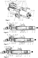
- FIG. 1 is a perspective view of a steering column with an outer jacket tube 1 and an inner jacket tube 2 shown.
- the inner jacket tube carries in its interior an upper steering shaft 3, which is rotatably mounted in a rolling bearing 4 about a longitudinal axis 5.
- the longitudinal axis 5 defines an axial direction of the steering column assembly, in which the inner jacket tube 2 relative to the outer jacket tube 1 is telescopically displaceable.
- the outer jacket tube 1 is held in a bracket 6, which is provided with cutouts 7 for fastening the bracket 6 to a vehicle body.
- the bracket 6 further has a tensioning device 8, which passes through the bracket 6 transversely to the longitudinal axis 5 and the height adjustment of the outer casing 1 relative to the bracket 6 and an axial adjustment of the inner casing 2 relative to the outer casing 1 allowed.
- the console 6 is provided with guide slots 9 and the inner jacket tube 2 is provided with a guide slot 10.
- the outer jacket tube 1 further carries a lower steering shaft or steering shaft 11, which is mounted in a rolling bearing not visible here within the outer jacket tube 1.
- the upper steering shaft 3 and the lower steering shaft 11 are rotatably but telescopically connected together, as is common in the art.
- the outer jacket tube 1 has at its top side facing away from each other longitudinal grooves 12, into which a support member 13 engages.
- the support member 13 is slidably mounted in the grooves in the direction of the longitudinal axis 5 on the outer casing tube 1 and there, in the example by caulking, attached.
- the support member 13 engages in the manner of a clip in the grooves 12 and surrounds the lying between the grooves 12 upper outer portion of the outer jacket tube 1.
- the support member 13 further comprises side walls 14, which in the assembled state according to FIG. 1 from the grooves 12 extend upward and are oriented with their flat sides parallel to the longitudinal axis 5 and with their short end faces transverse to the longitudinal axis 5.
- the sides 14 are each provided with an elongate recess 15 whose longitudinal axis is oriented parallel to the longitudinal axis 5.
- a tubular bush 16 is arranged, which defines a pivot axis 17.
- the pivot axis 17 is fixed to the motor vehicle and is aligned after mounting the steering column assembly in a motor vehicle substantially transverse to the direction of travel and horizontal.
- the pivot axis 17 serves as a bearing axis for the Vertikalverschwenkung, also called height adjustment, the steering column in operation.
- a T-slot 18 is provided in the support member 13, which extends parallel to the longitudinal axis 5.
- the T-slot 18 carries in its inner free cross-section a sliding block 19, which is fastened with a threaded screw 20 in the guide element.
- the outer jacket tube 1 has on its underside, which also when installed in a vehicle facing down, a longitudinal slot 21, in which a downwardly facing web 22, in the longitudinal direction of the longitudinal axis 5 at the bottom of the inner casing tube 2 in the extrusion process for the inner jacket tube 2 is formed with, is guided axially.
- the inner jacket tube 2 is displaceable in the outer jacket tube 1 for the purpose of Axial adjustment of the steering column as long as the tensioning device 8 is released and thus is in a release position.
- the tensioning device 8 is tensioned, the outer jacket tube 1 and thus the longitudinal slot 21 are contracted and the inner jacket tube 2 is clamped in order to fix the selected axial position.
- a width B of the longitudinal slot 21 is reduced during tensioning of the tensioning device 8.
- the width B corresponds to the extent of the longitudinal slot 21 in the direction of the clamping axis 27.
- the inner jacket tube 2 further has a circular inner cross-section, which can serve directly as a seat for a roller bearing 4.
- the rolling bearing 4 is inserted with a press fit into the inner jacket tube 2 and supports the driver-side end of the upper steering shaft 3 rotatably.
- FIG. 2 is the steering column off FIG. 1 shown in a longitudinal section from the side.
- FIG. 2 shows the internal structure of the steering column, which includes a second rolling bearing 24 for supporting the steering wheel facing away from the end of the upper steering shaft 3.
- the second rolling bearing 24 is used as well as the first rolling bearing 4 in the inner casing 2.
- the lower steering shaft 11 engages in the upper steering shaft 3.
- the two components each have a non-circular, for example, cloverleaf-shaped, and mutually play-free matching cross-section, so that they are rotationally fixed, but axially displaceable and telescopically guided into each other. Due to this guide, the lower steering shaft 11 requires only a rolling bearing for rotatable mounting.
- the rolling bearing 25 is by means of a fitting 26 in the outer jacket tube 1 at its free end, which is not penetrated by the inner jacket tube 2, used.
- FIG. 2 also illustrates the relative position of the inner jacket tube 2 to the outer jacket tube 1.
- the position shown here corresponds to a center position within the adjustment of the axial adjustment, which is available to the driver to adjust the steering wheel distance. This can be seen from the fact that a clamping axis 27 of the otherwise not visible here clamping device 8 is located centrally in the guide slot 10.
- the socket 16 in the recess on a Steering wheel remote end positioned.
- the sliding block is fixed in the T-slot 18 directly adjacent to the bushing 16, so that the bushing 16 between the end of the recess 15 and the sliding block 19 is fixed.
- FIG. 2 So shows an average setting of the steering column in normal operating condition.
- FIG. 3 which are essentially the FIG. 2 corresponds, the inner jacket tube 2 relative to the outer jacket tube 1 is shifted to the left into the outer jacket tube 1, so that the clamping axis 27 abuts the end of the guide slot 10 near the steering wheel.
- This position corresponds to an axial adjustment by the driver, in which the steering wheel has the greatest possible distance from the driver during normal driving and is thus fully inserted.
- FIG. 4 shows the steering column after the so-called crash, so after a frontal collision of the vehicle to an obstacle, in which the driver strikes the steering wheel.
- the assembly of the casing pipes 1 and 2 the bracket 6 and the support member 13 is shifted to the left, as in the direction of travel of the vehicle forward.
- the console slips in the area of the cutouts 7 from their attachments to the body.
- the amount of displacement corresponds to the length of the recess 15, which can be seen from the fact that the body-mounted bush 16 is now applied to the steering wheel near the end of the recess 15.
- FIG. 5 shows the steering column in a perspective view of the mounting of the lower steering shaft 11 in the outer casing 1, the storage is here in an exploded view.
- the outer jacket tube is, as already mentioned above, manufactured as an extruded part and therefore has over its longitudinal extension in the direction of the longitudinal axis 5 substantially uniform cross-section on the entire length. With respect to the longitudinal axis 5 is substantially obtained without major parts were machined by Zerspanungsoperation of the original blank.
- the inner space is bounded by an inner peripheral surface having four part-cylindrical surfaces and three rectangular grooves 23 therebetween.
- the part-cylindrical surfaces form an approximately circular cylindrical, tubular guide, in which the inner casing tube 2 is inserted.
- the grooves 23 and the bottom longitudinal slot 21 are distributed at 90 ° angular distance and form a cruciform extension of the otherwise round cross-section.
- the fitting piece 26 is used, which has a compatible outer peripheral surface with lugs 29, and a circular cylindrical annular inner bearing seat 28.
- the bearing seat 28 serves to receive the rolling bearing 25.
- the inner ring of the rolling bearing 25 in turn the bearing seat of the lower steering shaft 11.
- the rolling bearing 25 supports the lower steering shaft 11 in the fitting piece 26, which in turn is fixed in the outer jacket tube 1. Due to the shape of the outer jacket tube 1 and the fitting piece 26 as an extrusion, the positioning of the fitting piece 26 can be carried out at almost anywhere within the outer jacket tube 1.
- the bearing is therefore suitable for various designs, e.g. different length executable with identical parts.
- FIG. 6 shows a cross-section through the clamping axis 27 of the tensioning apparatus 8.
- the tensioning apparatus 8 further comprises a wedge-cam arrangement to clamp the outer casing 1, the inner casing 2 and the side walls 41 of the bracket 6 together.
- the tensioning device 8 is located in the illustrated cross section in the fixing position. In this fixing position, the width B of the longitudinal slot 21 of the outer jacket tube 1 is reduced or narrowed relative to the release position of the tensioning apparatus 8, not shown. Due to the reduced width B of the longitudinal slot, the diameter of the bore of the outer jacket tube 1, which serves to receive the inner jacket tube 2, also reduced.
- the inner jacket tube 2 is clamped in the outer jacket tube 2. If the tensioning apparatus 8 is transferred to the release position, then the width B of the longitudinal slot 21 and thus diameter of the bore of the outer jacket tube 1 increases, whereby the clamping of the inner jacket tube is canceled, so that a displacement of the inner jacket tube relative to the outer jacket tube in the axial direction is possible.
- FIG. 7 shows a perspective view of the steering column, in which the inner jacket tube 2 is pulled out of the outer jacket tube 1 out.
- the inner jacket tube 2 is formed with its bottom integrally formed web 22 so that it fits rotatably in the outer jacket tube 1 solely due to the shape.
- Next carries the inner casing 2 at its rear upper side a sliding insert 30.
- the web has the guide slot 10 which is penetrated by the clamping axis 27 of the tensioning apparatus 8, not shown here. Trained in the console 6 guide slot 9 corresponds to the trajectory of the clamping axis 27 relative to the console 6 in an adjustment in the vertical direction of the steering column in the motor vehicle.
- FIG. 8 is the guide of the inner jacket tube 2 in the outer jacket tube 1 shown in a cross section.
- the support member 13 in an end view.
- the inner jacket tube 2 carries on its upper side as anti-rotation the sliding insert 30, which engages in the upper groove 23 of the outer jacket tube 1.
- the slide insert 30 may also be made of a self-lubricating plastic.
- the support element 13 with the sliding block 19 and the sleeve 16 frictionally engaged therein has already been described above.
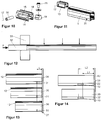
- FIG. 9 shows the outer jacket tube 1 with the support member 13 in a separate representation before placing the support member 13 on the casing tube 1.
- the position of a bore 31 is illustrated, which receives the clamping axis 27, not shown here.
- FIG. 10 shows the support member 13 with the sliding block 19 and the bushing 16 in an exploded view.
- FIG. 11 shows the outer jacket tube 1 with the support member 13 without nut and socket in a representation as in FIG. 9 ,
- FIG. 12 illustrates the process of producing the outer jacket tube 1.
- a pressing force F preferably at elevated temperature
- a strand of material 32 for example of an aluminum alloy or magnesium alloy
- the resulting molded part is then a blank with the cross-sectional shape of the outer jacket tube 1 including the longitudinal slot 21.
- the molding is separated at the marked with arrows points, for example by sawing. The length of the workpieces can be varied by selecting the separation points.
- FIG. 13 shows how a long blank 34, a medium-length blank 35 and a short blank 36 are processed by attaching functional elements.
- the functional elements are limited in this case to the bore 31 for receiving the clamping axis 27.
- This bore is at the three blanks 34, 35 and 36 at the same distance L from the right end face of the respective blank, here illustrated by a contact plate 37, attached .
- All other features of the outer jacket tube 1 are, as already described above, produced solely by the extrusion die. This applies, for example, for the grooves 12 and the others, in the FIG. 13 invisible features of the inner cross section. By cutting the blanks to length, different component lengths are realized.
- the attachment of the functional elements can be carried out in the same device, since only the front end face is used as the reference plane.
- FIG. 14 shows how a long blank 38 and a short blank 39 are processed by attaching functional elements respectively to an inner casing 2.
- the functional elements are limited in this case to the guide slot 10 which is introduced into the web 22.
- This guide slot 10 is mounted at the two blanks 38 and 39 in the same range from L1 to L2 measured from the right end face of the respective blank, illustrated here by a contact plate 40.
- All Other features of the inner jacket tube 2, as already described above, have been produced solely by the extrusion die. This applies, for example, to the bridge 22 and the others, in the FIG. 14 invisible features of the inner cross section.
- components for steering columns of different lengths and thus for different vehicle platforms can be manufactured in a particularly simple and cost-effective manner in uniform clamping from the same extruded part.
Landscapes
- Engineering & Computer Science (AREA)
- Mechanical Engineering (AREA)
- Chemical & Material Sciences (AREA)
- Combustion & Propulsion (AREA)
- Transportation (AREA)
- Steering Controls (AREA)
Description
- Die vorliegende Erfindung betrifft ein Verfahren zur Fertigung einer Lenksäule mit den Merkmalen des Oberbegriffs des Anspruchs 1.
- Lenksäulen haben in Kraftfahrzeugen vielfältige Funktionen. Zum einen dienen sie zur Befestigung des Lenkrades und zur Lagerung der Lenkwelle oder Lenkspindel an der Karosserie. Sie dienen auch zur Befestigung von Anbauteilen wie z. B. einer Diebstahlsicherung oder von Bedienelementen. Teilweise sind die Lenksäulen auch mechanisch oder elektrisch in Axialrichtung und Vertikalrichtung verstellbar, um die Position des Lenkrades an die Anforderungen des Fahrers anpassen zu können. Schließlich sollen Lenksäulen auch bei einem Aufprall des Fahrzeugs auf ein Hindernis kontrolliert nachgeben, um Aufprallenergie des Fahrers auf das Lenkrad zu absorbieren und dadurch das Verletzungsrisiko für den Fahrer zu vermindern. Bei all diesen Anforderungen wird außerdem gefordert, dass Lenksäulen einen kleinen Bauraum beanspruchen, ein geringes Gewicht aufweisen und spiel- und geräuschfrei arbeiten.
- Eine Möglichkeit, Lenksäulen preiswert und leicht zu gestalten, besteht in der Verwendung von Strangpressprofilen. Strangpressprofile haben gegenüber Druckgusskomponenten den Vorteil geringer Produktionskosten.
- Aus dem Stand der Technik sind deshalb bereits Lenksäulen bekannt, in denen Strangpressprofile eingesetzt werden. Das Dokument
US 8,863,609 B2 offenbart beispielsweise eine Lenksäule, bei der die Manteleinheit, genauer gesagt das äußere Mantelrohr, aus einem Strangpressprofil gefertigt ist. Diese Lenksäule weist die Besonderheit auf, dass die Spannachse für das Lösen und Blockieren der Verstellung einseitig an dem äußeren Mantelrohr angreift und nicht zu der anderen Seite des Mantelrohres durchgehend ist. - Das Dokument
FR 3004154 WO 2008/086548 A1 offenbart die Präambel der unabhängigen Ansprüche 1 und 13. - Es ist deshalb Aufgabe der vorliegenden Erfindung, ein Verfahren zur Herstellung einer Lenksäule für ein Kraftfahrzeug zu schaffen, das unter Verwendung von einem Strangpressprofil mit geringerem Bearbeitungsaufwand ausgeführt werden kann. Diese Aufgabe wird von einem Verfahren mit den Merkmalen des Anspruchs 1 gelöst. Vorteilhafte Weiterbildungen ergeben sich aus den Unteransprüchen. Weiterhin wird die Aufgabe durch eine Lenksäule mit den Merkmalen des Anspruchs 14 gelöst.
- Das Verfahren zur Herstellung einer Lenksäule für ein Kraftfahrzeug, wobei die Lenksäule ein inneres Mantelrohr, zur drehbaren Aufnahme einer Lenkwelle um ihre Längsachse, und ein äußeres Mantelrohr, das das innere Mantelrohr aufnimmt, umfasst, wobei das äußere Mantelrohr einen sich in Richtung der Längsachse erstreckenden Längsschlitz aufweist, wobei ein Spannapparat, der zwischen einer Freigabestellung, in der das innere Mantelrohr gegenüber dem äußeren Mantelrohr verstellbar ist, und einer Fixierstellung, in der das innere Mantelrohr gegenüber dem äußeren Mantelrohr fixiert ist, umschaltbar ist, wobei der Spannapparat einen Spannachse umfasst, die durch eine Ausnehmung im äußeren Mantelrohr quer zur Längsachse geführt ist und wobei der Längsschlitz in der Freigabestellung eine größere Breite aufweist als in der Fixierstellung,
gekennzeichnet durch folgende Verfahrensschritte: - a) Anfertigen eines einzelnen Rohlings des äußeren Mantelrohres in einem Strangpressverfahren, welcher den in Längsrichtung durchgehenden Längsschlitz aufweist,
- b) Ablängen des einzelnen Rohlings auf eine erforderliche Bauteillänge,
- c) Erzeugen von einer vordefinierten Anzahl von Ausnehmungen in einem vordefinierten Abstand von einer Stirnseite des Rohlings, mittels einer Zerspanungsoperation zur Ausbildung von Funktionselementen im äußeren Mantelrohr,
- g) Komplettieren der Lenksäule durch Anbringen von weiteren Bauelementen.
- Auf diese Weise ist es möglich, allein durch Auswahl der Länge des äußeren Mantelrohres und durch Fertigbearbeitung mittels einer Zerspanungsoperation in einer einzigen Aufspannung verschiedene Bauteillängen des äußeren Mantelrohrs für verschiedene Lenksäulen herzustellen, die modular für verschiedene Einbausituationen geeignet sind. Trotz der Zerspanungsoperation bleibt das Profil des Rohlings, welcher den in Längsrichtung durchgehenden Längsschlitz aufweist, im Wesentlichen über seine Länge erhalten, wobei im Wesentlichen die Profilstruktur erhalten bleibt. Lange und kurze Lenksäulen unterscheiden sich nur durch den Verfahrensschritt b), indem das Ablängen an unterschiedlichen Positionen erfolgt. Zur Komplettierung können Gleichteile verwendet werden.
- Unter Zerspanungsoperationen sind mechanische Trennverfahren mit geometrisch bestimmter und geometrisch unbestimmter Schneide zu verstehen, beispielsweise Bohren, Fräsen, Schleifen und Drehen. Das Ablängen kann auf verschiedene Arten erfolgen, beispielsweise Sägen, Laserschneiden oder Wasserstrahlschneiden.
- Vorteilhaft ist es, wenn das äußere Mantelrohr die Lenkwelle einteilig um mehr als 270° umschließt. Auf diese Weise kann eine optimale Abstützung der Lenkwelle im äußeren Mantelrohr erreicht werden. Bevorzugt umschließt das äußere Mantelrohr die Lenkwelle um mehr als 300°, wodurch die Lenksäule eine weitere Verbesserung der Abstützung erfährt und somit eine hohe Steifigkeit der Abstützung gewährleistet werden kann.
- In vorteilhafter Weise werden in den Strangpressrohling zur Ausbildung des äußeren Mantelrohrs ausschließlich Ausnehmungen, bevorzugt in Form von Öffnungen, und eventuell zusätzlich Planflächen mittels Zerspanung eingebracht.
- Unter Ausnehmungen sind Senkungen bzw. Vertiefungen oder Durchbrüche zu verstehen. Durchbrüche sind beispielsweise Langlöcher oder kreiszylindrische Bohrungen bzw. Gewindebohrungen. Bevorzugt sind am Strangpressprofil zur Ausbildung des äußeren Mantelrohrs ausschließlich Bohrungen oder Langlöcher, sowie Planflächen durch Nachbearbeitung eingebracht. Die Ausnehmung dienen bevorzugt als Funktionselemente, beispielsweise zur Ausbildung von Verstelllanglöchern und/oder Bohrungen zum Hindurchführen der Spannachse oder zur Aufnahme weiterer Bauelemente. Planflächen können vor allem in den Bereichen des äußeren Mantels vorgesehen sein, die als Kontaktflächen zur Paarung mit anderen Bauelementen vorgesehen sind. Durch diese Planflächen wird eine gute Paarung begünstigt.
- Bevorzugt umfasst das Verfahren weitere Verfahrensschritte vor dem Verfahrensschritt g):
- d) Anfertigen eines einzelnen Rohlings des inneren Mantelrohres, welcher den in Längsrichtung durchgehenden Längsschlitz aufweist, in einem Strangpressverfahren,
- e) Ablängen des einzelnen Rohlings auf eine erforderliche Bauteillänge,
- f) Erzeugen von einer vordefinierten Anzahl von Ausnehmungen in einem vordefinierten Abstand von einer Stirnseite des Rohlings, mittels einer Zerspanungsoperation zur Ausbildung von Funktionselementen im inneren Mantelrohr.
- Auf diese Weise ist es möglich, allein durch Auswahl der Länge des inneren Mantelrohres und durch Fertigbearbeitung mittels einer Zerspanungsoperation in einer einzigen Aufspannung für verschiedene Bauteillängen des inneren Mantelrohres für verschiedene Lenksäulen herzustellen, die modular für verschiedene Einbausituationen geeignet sind. Trotz der Zerspanungsoperation bleibt das Profil des Rohlings mit dem in Längsrichtung durchgehenden Längsschlitz im Wesentlichen über seine Länge erhalten, wobei im Wesentlichen die Profilstruktur erhalten bleibt. Lange und kurze Lenksäulen unterscheiden sich nur durch den Verfahrensschritt e), indem das Ablängen an unterschiedlichen Positionen erfolgt.
- Vorteilhaft ist es, wenn in jedem Längenbereich des äußeren und/oder inneren Mantelrohrs die Querschnittsfläche des Rohlings zur Ausbildung des äußeren und/oder Mantelrohrs mittels der Zerspanungsoperation maximal um 30% reduziert wird. Unter der Querschnittfläche ist dabei stets die Profilquerschnittsfläche zu verstehen, wobei diese orthogonal zur Längsachse ausgerichtet ist. Unter in jedem Längenbereich des äußeren und/oder inneren Mantelrohrs ist zu verstehen, dass die Querschnittsflächen an jedem beliebigen Längenabschnitt durch die Zerspanungsoperation maximal um 30% gegenüber der unbearbeiteten Querschnittsfläche des Rohlings reduziert sind. Auf diese Weise lässt sich eine kostengünstige Herstellung des äußeren und/oder inneren Mantelrohrs gewährleisten. Bevorzugt wird in jedem Längenbereich des äußeren und/oder inneren Mantelrohrs die Querschnittsfläche des Rohlings zur Ausbildung des äußeren und/oder Mantelrohrs mittels der Zerspanungsoperation maximal um 20%, besonders bevorzugt 10% und ganz besonders bevorzugt um 5%, reduziert.
- Vorteilhaft ist es, wenn das Komplettieren den Einbau der Lenkwelle umfasst. Bei der Lenkwelle handelt sich vorzugsweise um eine insbesondere zweiteilige und teleskopierbare Lenkwelle, wobei diese an einem Ende einen Kopplungsabschnitt zur Anbindung eines Lenkrades umfasst.
- Vorteilhaft ist es, wenn das Komplettieren den Anbau einer Konsole umfasst.
- Dabei kann der Anbau der Konsole die Montage des Spannapparates umfassen, der die Spannachse enthält, welche Funktionselemente des äußeren und/und oder inneren Mantelrohrs, beispielsweise in Form von Bohrungen und Führungsschlitzen, durchsetzt. Die Konsole umfasst dabei zumindest eine Seitenwange, wobei diese Seitenwange bevorzugt mit einer zumindest teilweise geplanten Fläche des äußeren Mantels in Kontakt bringbar ist. Insbesondere kann ein Tragelement auf eine lineare Nuten- oder Rippenstruktur auf das äußere Mantelrohr aufgesetzt werden, wobei das Tragelement zur Befestigung an der Karosserie des Fahrzeugs dient und an dem Mantelrohr einfach zu positionieren und zu befestigen ist. Je nach Positionierung ist der Befestigungspunkt wählbar, ohne dass das Mantelrohr dafür bearbeitet werden muss.
- Das Tragelement kann dabei vorteilhaft mit einer Buchse versehen werden, die als Befestigungselement an der Karosserie oder der Konsole dient und die außerdem Lagerachse für eine Schwenkbewegung bei einer Höhenverstellung der Lenksäule aufnimmt.
- Vorzugsweise ist die Lenkwelle teleskopierbar und wird mittels Wälzlagern in das innere und/oder äußere Mantelrohr eingesetzt und dort drehbar gelagert.
- Es ist weiter von Vorteil, wenn wenigstens ein Wälzlager mittels eines Passstückes in das äußere Mantelrohr eingesetzt wird. Der Lagersitz kann dann in einfacher Weise in dem Passstück ausgebildet sein.
- Zuverlässig gehalten und dauerhaft geräuscharm wird die Lagerung, wenn das Passstück unverdrehbar in dem äußeren Mantelrohr angeordnet wird.
- Vorteilhaft ist auch eine nach dem beschriebenen Verfahren hergestellte verstellbare Lenksäule, weil durch die einfache modulare Bauweise und die einfache Fertigung unterschiedlicher Lenksäulen unter Verwendung von Gleichteilen für verschiedene Typen Kostenvorteile ergeben.
- Weiterhin wird eine Lenksäule für ein Kraftfahrzeug vorgeschlagen, wobei die Lenksäule ein inneres Mantelrohr zur drehbaren Aufnahme einer Lenkwelle um ihre Längsachse, und ein äußeres Mantelrohr, das das innere Mantelrohr aufnimmt, umfasst, wobei das äußere Mantelrohr einen sich in Richtung der Längsachse erstreckenden Längsschlitz aufweist, wobei ein Spannapparat, der zwischen einer Freigabestellung, in der das innere Mantelrohr gegenüber dem äußeren Mantelrohr verstellbar ist, und einer Fixierstellung, in der das innere Mantelrohr gegenüber dem äußeren Mantelrohr fixiert ist, umschaltbar ist, wobei der Spannapparat einen Spannbolzen umfasst, der durch eine Ausnehmung im äußeren Mantelrohr quer zur Längsachse geführt ist und wobei der Längsschlitz in der Freigabestellung eine größere Breite aufweist als in der Fixierstellung. Erfindungsgemäß ist das äußere Mantelrohr in einem Strangpressverfahren hergestellt, das auf eine erforderliche Bauteillänge abgelängt wurde, und eine vordefinierte Anzahl von Ausnehmungen aufweist, die in einem vordefinierten Abstand von einer Stirnseite des Rohlings, welcher den in Längsrichtung durchgehenden Längsschlitz aufweist, angeordnet sind, wobei das äußere Mantelrohr das innere Mantelrohr einstückig um mindestens 270° umschließt. Mit Vorteil umschließt das äußere Mantelrohr das innere Mantelrohr um mehr als 300°.
- Diese Lenksäule bietet den Vorteil einer kostengünstigen Herstellung und die Möglichkeit mit sehr ähnlichen Bauteilen, die sich nur durch wenige Bearbeitungsschritte voneinander unterscheiden, verschiedene Lenksäulen für verschiedene Fahrzeuge darzustellen.
- Nachfolgend wird ein Ausführungsbeispiel der vorliegenden Erfindung anhand der Zeichnung beschrieben. Es zeigen:
- Figur 1:
- eine erfindungsgemäße Lenksäule in einer perspektivischen Darstellung;
- Figur 2:
- die Lenksäule aus
Figur 2 in einem Längsschnitt von der Seite; - Figur 3:
- die Lenksäule aus
Figur 2 in einer anderen Verstellposition; - Figur 4:
- die Lenksäule aus
Figur 2 und Figur 3 in zusammengeschobener Stellung nach einem Aufprall; - Figur 5:
- die Lenksäule aus
Figur 1 in einer perspektivischen Ansicht von der dem Lenkrad abgewandten Seite her; - Figur 6:
- einen Querschnitt durch die Lenksäule im Bereich einer Spannachse;
- Figur 7:
- einen perspektivischen Ausschnitt einer Lenksäulenanordnung mit separiertem innerem Mantelrohr;
- Figur 8:
- einen anderen Querschnitt mit aufgesetztem Tragelement;
- Figur 9:
- eine perspektivische Ansicht des äußeren Mantelrohrs mit separiertem Tragelement;
- Figur 10:
- den Tragschlitten mit weiteren Komponenten in einer Explosionsdarstellung;
- Figur 11:
- eine Darstellung entsprechend
Figur 9 mit veranschaulichter Schwenkachse; - Figur 12:
- eine schematische Darstellung der Fertigung des äußeren Mantelrohres im Strangpressverfahren mit angedeuteten Trennstellen für die Auftrennung des Strangpressprofils in einzelne Rohlinge für äußere Mantelrohre;
- Figur 13:
- äußere Mantelrohre in verschiedener Länge mit Veranschaulichung der einheitlichen Lage eines Funktionsbereichs; sowie
- Figur 14:
- eine Seitenansicht ähnlich
Figur 13 mit der Darstellung von zwei inneren Mantelrohren, bei denen ebenfalls die Lage eines Funktionsbereichs dargestellt ist. - Gleiche oder vergleichbare Bauelemente in verschiedenen Ausführungsbeispielen tragen dieselben Bezugsziffern.
- In der
Figur 1 ist in perspektivischer Ansicht eine Lenksäule mit einem äußeren Mantelrohr 1 und einem inneren Mantelrohr 2 dargestellt. Das innere Mantelrohr trägt in seinem Inneren eine obere Lenkspindel 3, die in einem Wälzlager 4 um eine Längsachse 5 drehbar gelagert ist. Die Längsachse 5 definiert eine Axialrichtung der Lenksäulenanordnung, in der das innere Mantelrohr 2 gegenüber dem äußeren Mantelrohr 1 teleskopähnlich verschieblich ist. - Das äußere Mantelrohr 1 ist in einer Konsole 6 gehalten, die mit Ausschnitten 7 zur Befestigung der Konsole 6 an einer Fahrzeugkarosserie versehen ist. Die Konsole 6 weist weiter einen Spannapparat 8 auf, der die Konsole 6 quer zu der Längsachse 5 durchsetzt und der eine Höhenverstellung des äußeren Mantelrohrs 1 gegenüber der Konsole 6 und eine Axialverstellung des inneren Mantelrohrs 2 gegenüber dem äußeren Mantelrohr 1 erlaubt. Zu diesem Zweck ist die Konsole 6 mit Führungsschlitzen 9 versehen und das innere Mantelrohr 2 ist mit einem Führungsschlitz 10 versehen.
- Das äußere Mantelrohr 1 trägt weiter eine untere Lenkwelle oder Lenkspindel 11, die in einem hier nicht sichtbaren Wälzlager innerhalb des äußeren Mantelrohrs 1 gelagert ist. Die obere Lenkspindel 3 und die untere Lenkspindel 11 sind drehfest, aber teleskopierbar miteinander verbunden, wie dies im Stand der Technik üblich ist.
- Das äußere Mantelrohr 1 weist an seiner Oberseite einander abgewandte Längsnuten 12 auf, in die ein Tragelement 13 eingreift. Das Tragelement 13 ist in den Nuten schlittenartig in Richtung der Längsachse 5 auf das äußere Mantelrohr 1 aufgesetzt und dort, im Beispiel durch Verstemmen, befestigt. Das Tragelement 13 greift dazu klammerartig in die Nuten 12 ein und umgreift den zwischen den Nuten 12 liegenden oberen äußeren Abschnitt des äußeren Mantelrohrs 1. Die Befestigung kann ebenfalls durch eine Übermaßpassung (= Presspassung) oder Kleben erfolgen. Das Tragelement 13 weist weiterhin Seitenwände 14 auf, die sich in montiertem Zustand gemäß
Figur 1 von den Nuten 12 nach oben erstrecken und die mit ihren Flachseiten parallel zu der Längsachse 5 sowie mit ihren kurzen Stirnseiten quer zu der Längsachse 5 orientiert sind. Die Seiten 14 sind jeweils mit einer länglichen Ausnehmung 15 versehen, deren Längsachse parallel zu der Längsachse 5 orientiert ist. In den Ausnehmungen 15 quer zu der Längsachse 5 ist eine rohrförmige Buchse 16 angeordnet, die eine Schwenkachse 17 definiert. Die Schwenkachse 17 ist am Kraftfahrzeug befestigt und ist nach Montage der Lenksäulenanordnung in einem Kraftfahrzeug im Wesentlichen quer zu der Fahrtrichtung und horizontal ausgerichtet. Die Schwenkachse 17 dient als Lagerachse für die Vertikalverschwenkung, auch Höhenverstellung genannt, der Lenksäule im Betrieb. - Zwischen den Seiten 14 ist in dem Tragelement 13 eine T-Nut 18 vorgesehen, die sich parallel zu der Längsachse 5 erstreckt. Die T-Nut 18 trägt in ihrem inneren freien Querschnitt einen Nutenstein 19, der mit einer Gewindeschraube 20 in dem Führungselement befestigbar ist.
- Das äußere Mantelrohr 1 weist an seiner Unterseite, die auch bei Einbau in ein Fahrzeug nach unten weist, einen Längsschlitz 21 auf, in dem ein nach unten weisender Steg 22, der in Längsrichtung der Längsachse 5 an der Unterseite des inneren Mantelrohres 2 beim Strangpressverfahren für das innere Mantelrohr 2 mit angeformt ist, axial geführt ist. Im Betrieb ist das innere Mantelrohr 2 in dem äußeren Mantelrohr 1 verschiebbar zum Zwecke der Axialverstellung der Lenksäule, solange der Spannapparat 8 gelöst ist und sich somit in einer Freigabestellung befindet. Bei gespanntem Spannapparat 8 wird das äußere Mantelrohr 1 und somit der Längsschlitzes 21 zusammengezogen und das innere Mantelrohr 2 geklemmt, um die gewählte Axialposition zu fixieren. Eine Breite B des Längsschlitzes 21 wird beim Spannen des Spannapparates 8 reduziert. Die Breite B entspricht der Ausdehnung des Längsschlitzes 21 in Richtung der Spannachse 27.
- Das innere Mantelrohr 2 weist weiter einen kreisrunden inneren Querschnitt auf, der unmittelbar als Sitz für ein Wälzlager 4 dienen kann. Vorzugsweise ist das Wälzlager 4 mit einem Presssitz in das inneren Mantelrohr 2 eingesetzt und lagert das fahrerseitige Ende der oberen Lenkspindel 3 drehbar.
- In der
Figur 2 ist die Lenksäule ausFigur 1 in einem Längsschnitt von der Seite dargestellt. - Die
Figur 2 zeigt den inneren Aufbau der Lenksäule, der ein zweites Wälzlager 24 zur Lagerung des lenkradabgewandten Endes der oberen Lenkspindel 3 umfasst. Das zweite Wälzlager 24 ist ebenso wie das erste Wälzlager 4 in das innere Mantelrohr 2 eingesetzt. Es ist weiter dargestellt, wie die untere Lenkspindel 11 in die obere Lenkspindel 3 eingreift. Die beiden Bauelemente weisen jeweils einen unrunden, beispielsweise kleeblattförmigen, und zueinander spielfrei passenden Querschnitt auf, so dass sie drehfest, aber axial verschieblich und teleskopierbar ineinander geführt sind. Aufgrund dieser Führung benötigt die untere Lenkspindel 11 nur ein Wälzlager zur drehbaren Lagerung. Das Wälzlager 25 ist mittels eines Passstücks 26 in das äußere Mantelrohr 1 an dessen freiem Ende, welches nicht von dem inneren Mantelrohr 2 durchsetzt ist, eingesetzt. -
Figur 2 veranschaulicht auch die relative Position des inneren Mantelrohres 2 zu dem äußeren Mantelrohr 1. Die hier dargestellte Position entspricht einer Mittelstellung innerhalb des Verstellbereichs der Axialverstellung, der dem Fahrer zur Anpassung des Lenkradabstandes zur Verfügung steht. Dies ist erkennbar daran, dass eine Spannachse 27 des ansonsten hier nicht sichtbaren Spannapparates 8 mittig in dem Führungsschlitz 10 liegt. Weiter ist in der Position gemäßFigur 2 die Buchse 16 in der Ausnehmung an einem lenkradfernen Ende positioniert. Der Nutenstein ist in der T-Nut 18 unmittelbar anliegend an der Buchse 16 befestigt, so dass die Buchse 16 zwischen dem Ende der Ausnehmung 15 und dem Nutenstein 19 festgelegt ist. -
Figur 2 zeigt also eine mittlere Einstellung der Lenksäule bei normalem Betriebszustand. - In der
Figur 3 , die im wesentlichen derFigur 2 entspricht, ist das innere Mantelrohr 2 gegenüber dem äußeren Mantelrohr 1 nach links in das äußere Mantelrohr 1 hinein verschoben, so dass die Spannachse 27 an dem lenkradnahen Ende des Führungsschlitzes 10 anliegt. Diese Position entspricht einer Axialverstellung durch den Fahrer, bei der das Lenkrad den im normalen Fahrbetrieb größtmöglichen Abstand vom Fahrer aufweist und somit voll eingeschoben ist. - Die
Figur 4 zeigt die Lenksäule nach dem so genannten Crashfall, also nach einem Frontalaufprall des Fahrzeugs auf ein Hindernis, bei dem der Fahrer auf das Lenkrad prallt. Ausgehend von der Stellung gemäßFigur 3 ist die Baugruppe aus den Mantelrohren 1 und 2, der Konsole 6 und dem Tragelement 13 nach links verschoben, als in Fahrtrichtung des Fahrzeugs nach vorne. Die Konsole rutscht dabei im Bereich der Ausschnitte 7 aus ihren Befestigungen an der Karosserie. Der Betrag der Verschiebung entspricht der Länge der Ausnehmung 15, was daran erkennbar ist, dass die karosseriefeste Buchse 16 nun am lenkradnahen Ende der Ausnehmung 15 anliegt. Während des Aufpralls verschiebt sich also auch das Tragelement 13 unter dem Einfluss der entstehenden Kraft, welche zumindest mit einer Komponente in Richtung der Längsachse 5 wirkt, gegen die Buchse 16. Der Nutenstein 19 rutscht dabei entlang der T-Nut 18. Die mittels der Gewindeschraube 20 erzeugte Klemmkraft bewirkt dabei eine Reibung des Nutensteins 19 innerhalb der T-Nut 18, die zu einer Energieabsorption führt. Diese Energieabsorption ist gewünscht, da sie den Aufprall des Fahrers auf das Lenkrad dämpft und dadurch das Verletzungsrisiko bei einem Crash verringert. -
Figur 5 zeigt die Lenksäule in einer perspektivischen Ansicht auf die Lagerung der unteren Lenkspindel 11 in dem äußeren Mantelrohr 1, wobei die Lagerung hier in Explosionsdarstellung vorliegt. Das äußere Mantelrohr ist, wie bereits oben erwähnt, als Strangpressteil gefertigt und weist deshalb über seine Längserstreckung in Richtung der Längsachse 5 im wesentlichen gleichförmigen Querschnitt auf der über die gesamte Länge bzgl. der Längsachse 5 im Wesentlichen erhalten ist, ohne dass mittels Zerspanungsoperation größere Abschnitte von dem ursprünglichen Rohling zerspant wurden. Insbesondere ist der Innenraum von einer inneren Umfangsfläche begrenzt, die vier teilzylindrische Flächen und drei dazwischen liegende rechteckige Nuten 23 aufweist. Die teilzylindrischen Flächen bilden eine etwa kreiszylindrische, rohrförmige Führung, in die das innere Mantelrohr 2 eingesetzt ist. Die Nuten 23 und der unten angeordnete Längsschlitz 21 sind in 90° Winkelabstand verteilt und bilden eine kreuzförmige Erweiterung des im Übrigen runden Querschnitts. - In diese lichte Öffnung des äußeren Mantelrohres 1 wird das Passstück 26 eingesetzt, das eine kompatible äußere Umfangsfläche mit Ansätzen 29 aufweist, sowie einen kreiszylindrischen ringförmigen innen angeordneten Lagersitz 28. Der Lagersitz 28 dient zur Aufnahme des Wälzlagers 25. Der Innenring des Wälzlagers 25 wiederum nimmt den Lagersitz der unteren Lenkspindel 11 auf. Somit lagert das Wälzlager 25 die untere Lenkspindel 11 in dem Passstück 26, welche wiederum in dem äußeren Mantelrohr 1 fixiert ist. Aufgrund der Ausformung des äußeren Mantelrohres 1 und des Passstücks 26 als Strangpressteil kann die Positionierung des Passstücks 26 an nahezu beliebiger Stelle innerhalb des äußeren Mantelrohres 1 erfolgen. Die Lagerung ist deshalb für verschiedene Ausführungen, z.B. unterschiedlicher Länge mit Gleichteilen ausführbar.
-
Figur 6 zeigt einen Querschnitt durch die Spannachse 27 des Spannapparates 8. Der Spannapparat 8 umfasst weiterhin eine Keilscheiben-Nocken-Anordnung, um das äußere Mantelrohr 1, das innere Mantelrohr 2 und die Seitenwangen 41 der Konsole 6 miteinander zu verspannen. Der Spannapparat 8 befindet sich in dem abgebildeten Querschnitt in der Fixierstellung. In dieser Fixierstellung ist die Breite B des Längsschlitz 21 des äußeren Mantelrohr 1 gegenüber der nicht dargestellten Freigabestellung des Spannapparates 8 reduziert bzw. verschmälert. Durch die reduzierte Breite B des Längschlitzes ist der Durchmesser der Bohrung des äußeren Mantelrohr 1, welche zur Aufnahme des inneren Mantelrohres 2 dient, ebenfalls reduziert. - Dadurch wird das innere Mantelrohr 2 im äußeren Mantelrohr 2 geklemmt. Wird der Spannapparat 8 in die Freigabestellung überführt, so vergrößert sich die Breite B des Längsschlitzes 21 und somit Durchmesser der Bohrung des äußeren Mantelrohrs 1, wodurch die Klemmung des inneren Mantelrohrs aufgehoben wird, so dass eine Verschiebung des inneren Mantelrohrs gegenüber des äußeren Mantelrohr in Axialrichtung ermöglicht wird.
- Die
Figur 7 zeigt eine perspektivische Ansicht der Lenksäule, bei der das innere Mantelrohr 2 aus dem äußeren Mantelrohr 1 heraus gezogen ist. Das innere Mantelrohr 2 ist mit seinem unten angeformten Steg 22 so ausgebildet, dass es allein aufgrund der Form drehfest in das äußere Mantelrohr 1 passt. Weiter trägt das innere Mantelrohr 2 an seiner hinteren Oberseite eine Gleiteinlage 30. Der Steg weist den Führungsschlitz 10 auf, der von der hier nicht dargestellten Spannachse 27 des Spannapparats 8 durchsetzt ist. Der in der Konsole 6 ausgebildete Führungsschlitz 9 entspricht Bewegungsbahn der Spannachse 27 gegenüber der Konsole 6 bei einem Verstellvorgang in vertikaler Richtung der Lenksäule im Kraftfahrzeug. - In der
Figur 8 ist in einem Querschnitt die Führung des inneren Mantelrohres 2 in dem äußeren Mantelrohr 1 gezeigt. Zugleich zeigtFigur 8 das Tragelement 13 in einer Stirnansicht. Das innere Mantelrohr 2 trägt an seiner Oberseite als Verdrehsicherung die Gleiteinlage 30, die in die obere Nut 23 des äußeren Mantelrohres 1 eingreift. Die Gleiteinlage 30 kann auch einem selbstschmierenden Kunststoff hergestellt sein. Das Tragelement 13 mit dem darin reibschlüssig angeordneten Nutenstein 19 und der Buchse 16 wurde bereits oben beschrieben. -
Figur 9 zeigt das äußere Mantelrohr 1 mit dem Tragelement 13 in getrennter Darstellung vor dem Aufsetzen des Tragelements 13 auf das Mantelrohr 1. In dieser Darstellung ist die Lage einer Bohrung 31 veranschaulicht, die die hier nicht dargestellte Spannachse 27 aufnimmt. -
Figur 10 zeigt das Tragelement 13 mit dem Nutenstein 19 und der Buchse 16 in einer Explosionsdarstellung. -
Figur 11 zeigt das äußere Mantelrohr 1 mit dem Tragelement 13 ohne Nutenstein und Buchse in einer Darstellung wie inFigur 9 . -
Figur 12 veranschaulicht dein Herstellungsverfahren des äußeren Mantelrohres 1. Von der linken Seite der Figur her wird unter einer Presskraft F, bevorzugt bei erhöhter Temperatur, ein Materialstrang 32, zum Beispiel aus einer Aluminiumlegierung oder Magnesiumlegierung, durch eine Form 33 gepresst. Das entstehende Formteil ist dann ein Rohling mit der Querschnittsform des äußeren Mantelrohres 1 einschließlich des Längsschlitzes 21. Zur Trennung in einzelne Werkstücke wird das Formteil an den mit Pfeilen gekennzeichneten Stellen getrennt, beispielsweise durch Sägen. Die Länge der Werkstücke kann durch Wahl der Trennstellen variiert werden. -
Figur 13 zeigt, wie ein langer Rohling 34, ein mittellanger Rohling 35 und ein kurzer Rohling 36 durch Anbringen von Funktionselementen bearbeitet werden. Die Funktionselemente beschränken sich in diesem Fall auf die Bohrung 31 zur Aufnahme der Spannachse 27. Diese Bohrung wird bei den drei Rohlingen 34, 35 und 36 in dem gleichen Abstand L von der rechten Stirnfläche des jeweiligen Rohlings, hier veranschaulicht durch eine Anlageplatte 37, angebracht. Alle anderen Merkmale des äußeren Mantelrohres 1 sind, wie bereits oben beschrieben wurde, allein durch die Strangpressform erzeugt worden. Die gilt beispielsweise für die Nuten 12 und die anderen, in derFigur 13 nicht sichtbaren Merkmale des inneren Querschnitts. Allein durch das Ablängen der Rohlinge werden verschiedene Bauteillängen realisiert. Das Anbringen der Funktionselemente kann in derselben Vorrichtung erfolgen, da als Bezugsebene ausschließlich die vordere Stirnfläche benutzt wird. -
Figur 14 zeigt, wie ein langer Rohling 38 und ein kurzer Rohling 39 durch Anbringen von Funktionselementen jeweils zu einem inneren Mantelrohr 2 bearbeitet werden. Die Funktionselemente beschränken sich in diesem Fall auf den Führungsschlitz 10, der in den Steg 22 eingebracht wird. Dieser Führungsschlitz 10 wird bei den beiden Rohlingen 38 und 39 in dem gleichen Bereich von L1 bis L2 gemessen von der rechten Stirnfläche des jeweiligen Rohlings angebracht, hier veranschaulicht durch eine Anlageplatte 40. Alle anderen Merkmale des inneren Mantelrohres 2 sind, wie sie bereits oben beschrieben wurden, allein durch die Strangpressform erzeugt worden. Dies gilt beispielsweise für den Steg 22 und die anderen, in derFigur 14 nicht sichtbaren Merkmale des inneren Querschnitts. - Allein durch das Ablängen der Rohlinge werden verschiedene Bauteillängen realisiert. Das Anbringen der Funktionselemente kann in derselben Vorrichtung erfolgen, da als Bezugsebene ausschließlich die vordere Stirnfläche benutzt wird.
- So können in einheitlicher Aufspannung aus demselben Strangpressteil Komponenten für Lenksäulen verschiedener Längen und damit für verschiedene Fahrzeugplattformen in besonders einfacher und kostengünstiger Weise gefertigt werden.
-
- 1.
- äußeres Mantelrohr
- 2.
- inneres Mantelrohr
- 3.
- Lenkspindel
- 4.
- Wälzlager
- 5.
- Längsachse
- 6.
- Konsole
- 7.
- Ausschnitte
- 8.
- Spannapparat
- 9.
- Führungsschlitze
- 10.
- Führungsschlitz
- 11.
- Lenkspindel
- 12.
- Nuten
- 13.
- Tragelement
- 14.
- Seitenwände
- 15.
- Ausnehmung
- 16.
- rohrförmige Buchse
- 17.
- Schwenkachse
- 18.
- T-Nut
- 19.
- Nutenstein
- 20.
- Gewindeschraube
- 21.
- Längsschlitz
- 22.
- Steg
- 23.
- Nut
- 24.
- Wälzlager
- 25.
- Wälzlager
- 26.
- Passstück
- 27.
- Spannachse
- 28.
- Lagersitz
- 29.
- Ansatz
- 30.
- Gleiteinlage
- 31.
- Bohrung
- 32.
- Materialstrang
- 33.
- Form
- 34.
- Rohling
- 35.
- Rohling
- 36.
- Rohling
- 37.
- Anlageplatte
- 38.
- Rohling
- 39.
- Rohling
- 40.
- Anlageplatte
- 41.
- Seitenwange
- B
- Breite des Längsschlitzes
Claims (13)
- Verfahren zur Herstellung einer Lenksäule für ein Kraftfahrzeug, wobei die Lenksäule ein inneres Mantelrohr (2), zur drehbaren Aufnahme einer Lenkwelle (3, 11) um ihre Längsachse, und ein äußeres Mantelrohr (1), das das innere Mantelrohr (2) aufnimmt, umfasst, wobei das äußere Mantelrohr (1) einen sich in Richtung der Längsachse erstreckenden Längsschlitz (21) aufweist, wobei ein Spannapparat (8), der zwischen einer Freigabestellung, in der das innere Mantelrohr (2) gegenüber dem äußeren Mantelrohr (2) verstellbar ist, und einer Fixierstellung, in der das innere Mantelrohr (2) gegenüber dem äußeren Mantelrohr (2) fixiert ist, umschaltbar ist, wobei der Spannapparat (8) eine Spannachse (27) umfasst, die durch eine Ausnehmung im äußeren Mantelrohr (1) quer zur Längsachse geführt ist und wobei der Längsschlitz (21) in der Freigabestellung eine größere Breite aufweist als in der Fixierstellung, dadurch gekennzeichnet, dass das Verfahren folgende Verfahrensschritte aufweist:a) Anfertigen eines einzelnen Rohlings des äußeren Mantelrohres (1), welcher den in Längsrichtung durchgehenden Längsschlitz (21) aufweist, in einem Strangpressverfahren,b) Ablängen des einzelnen Rohlings auf eine erforderliche Bauteillänge,c) Erzeugen von einer vordefinierten Anzahl von Ausnehmungen in einem vordefinierten Abstand (L, L1, L2) von einer Stirnseite des Rohlings, mittels einer Zerspanungsoperation zur Ausbildung von Funktionselementen (31) im äußeren Mantelrohr (1),g) Komplettieren der Lenksäule durch Anbringen von weiteren Bauelementen.
- Verfahren zur Herstellung einer Lenksäule nach Anspruch 1, dadurch gekennzeichnet, dass das äußere Mantelrohr (1) die Lenkwelle (3) einteilig um mehr als 270° umschließt.
- Verfahren zur Herstellung einer Lenksäule nach einem der vorhergehenden Ansprüche, dadurch gekennzeichnet, dass in den Strangpressrohling zur Ausbildung des äußeren Mantelrohrs (1) ausschließlich Ausnehmungen, bevorzugt in Form von Öffnungen, und eventuell zusätzlich Planflächen mittels Zerspanung eingebracht werden.
- Verfahren zur Herstellung einer Lenksäule nach einem der vorhergehenden Ansprüche gekennzeichnet durch folgende weitere Verfahrensschritte vor dem Verfahrensschritt g):d) Anfertigen eines einzelnen Rohlings des inneren Mantelrohres (2), welcher den in Längsrichtung durchgehenden Längsschlitz (21) aufweist, in einem Strangpressverfahren,e) Ablängen des einzelnen Rohlings auf eine erforderliche Bauteillänge,f) Erzeugen von einer vordefinierten Anzahl von Ausnehmungen in einem vordefinierten Abstand (L, L1, L2) von einer Stirnseite des Rohlings, mittels einer Zerspanungsoperation zur Ausbildung von Funktionselementen (10) im inneren Mantelrohr (2).
- Verfahren zur Herstellung einer Lenksäule nach einem der vorhergehenden Ansprüche, dadurch gekennzeichnet, dass in jedem Längenbereich des äußeren und/oder inneren Mantelrohrs (1, 2) die Querschnittsfläche des Rohlings zur Ausbildung des äußeren und/oder Mantelrohrs (1, 2) mittels der Zerspanungsoperation maximal um 30% reduziert wird.
- Verfahren nach einem der vorhergehenden Ansprüche, dadurch gekennzeichnet, dass das Komplettieren den Einbau einer Lenkwelle (3, 11) umfasst.
- Verfahren nach einem der vorhergehenden Ansprüche, dadurch gekennzeichnet, dass das Komplettieren den Anbau einer Konsole (6) umfasst.
- Verfahren nach einem der vorhergehenden Ansprüche, dadurch gekennzeichnet, dass das Komplettieren der Lenksäule die Montage des Spannapparates (8) umfasst, wobei die Spannachse (27), die Funktionselemente (10, 31) im inneren und/oder im äußeren Mantelrohr (1, 2) durchsetzt.
- Verfahren nach einem der vorhergehenden Ansprüche, dadurch gekennzeichnet, dass ein Tragelement (13) auf das äußere Mantelrohr (1) aufgesetzt wird.
- Verfahren nach Anspruch 6, dadurch gekennzeichnet, dass das Tragelement (13) mit einer Buchse (16) versehen wird.
- Verfahren nach einem der vorhergehenden Ansprüche, dadurch gekennzeichnet, dass die Lenkwelle (3, 11) teleskopierbar ist und mittels Wälzlagern im inneren und/oder äußeren Mantelrohr drehbar gelagert ist.
- Verstellbare Lenksäule hergestellt nach einem Verfahren mit den Merkmalen wenigstens eines der vorhergehenden Ansprüche.
- Lenksäule für ein Kraftfahrzeug, wobei die Lenksäule ein inneres Mantelrohr (2), zur drehbaren Aufnahme einer Lenkwelle (3, 11) um ihre Längsachse, und ein äußeres Mantelrohr (1), das das innere Mantelrohr (2) aufnimmt, umfasst, wobei das äußere Mantelrohr (1) einen sich in Richtung der Längsachse erstreckenden Längsschlitz (21) aufweist, wobei ein Spannapparat (8), der zwischen einer Freigabestellung, in der das innere Mantelrohr (2) gegenüber dem äußeren Mantelrohr (2) verstellbar ist, und einer Fixierstellung, in der das innere Mantelrohr (2) gegenüber dem äußeren Mantelrohr (2) fixiert ist, umschaltbar ist, wobei der Spannapparat (8) einen Spannbolzen umfasst, der durch eine Ausnehmung im äußeren Mantelrohr quer zur Längsachse geführt ist und wobei der Längsschlitz (21) in der Freigabestellung eine größere Breite aufweist als in der Fixierstellung,
dadurch gekennzeichnet,
dass das äußere Mantelrohr (1) in einem Strangpressverfahren hergestellt ist, das auf eine erforderliche Bauteillänge abgelängt wurde, und eine vordefinierte Anzahl von Ausnehmungen aufweist, die in einem vordefinierten Abstand (L, L1, L2) von einer Stirnseite des Rohlings, welcher den in Längsrichtung durchgehenden Längsschlitz (21) aufweist, angeordnet sind, wobei das äußere Mantelrohr (1) das innere Mantelrohr (2) einstückig um mindestens 270° umschließt.
Priority Applications (1)
| Application Number | Priority Date | Filing Date | Title |
|---|---|---|---|
| PL15771896T PL3242826T3 (pl) | 2015-01-08 | 2015-09-22 | Sposób wytwarzania modułowej kolumny kierownicy za pomocą profili wytłaczanych |
Applications Claiming Priority (2)
| Application Number | Priority Date | Filing Date | Title |
|---|---|---|---|
| DE102015000028.4A DE102015000028A1 (de) | 2015-01-08 | 2015-01-08 | Fertigungsverfahren für eine modulare Lenksäule mit Strangpressprofilen |
| PCT/EP2015/071742 WO2016110335A1 (de) | 2015-01-08 | 2015-09-22 | Fertigungsverfahren für eine modulare lenksäule mit strangpressprofilen |
Publications (2)
| Publication Number | Publication Date |
|---|---|
| EP3242826A1 EP3242826A1 (de) | 2017-11-15 |
| EP3242826B1 true EP3242826B1 (de) | 2019-08-28 |
Family
ID=54238407
Family Applications (1)
| Application Number | Title | Priority Date | Filing Date |
|---|---|---|---|
| EP15771896.6A Active EP3242826B1 (de) | 2015-01-08 | 2015-09-22 | Fertigungsverfahren für eine modulare lenksäule mit strangpressprofilen |
Country Status (7)
| Country | Link |
|---|---|
| US (1) | US10370023B2 (de) |
| EP (1) | EP3242826B1 (de) |
| CN (1) | CN107454880B (de) |
| DE (1) | DE102015000028A1 (de) |
| ES (1) | ES2751676T3 (de) |
| PL (1) | PL3242826T3 (de) |
| WO (1) | WO2016110335A1 (de) |
Families Citing this family (10)
| Publication number | Priority date | Publication date | Assignee | Title |
|---|---|---|---|---|
| CN109476335B (zh) * | 2016-07-19 | 2021-06-04 | 日本精工株式会社 | 转向装置 |
| CN110546059B (zh) * | 2017-06-14 | 2022-05-17 | 日本精工株式会社 | 转向柱装置 |
| FR3074470B1 (fr) * | 2017-12-04 | 2019-11-22 | Jtekt Europe | Fabrication d’une piece superieure d’un element support de direction assistee sans cordon de soudure |
| DE102018204735A1 (de) | 2018-03-28 | 2018-10-11 | Thyssenkrupp Ag | Lenksäule für ein Kraftfahrzeug |
| JP2019189047A (ja) * | 2018-04-25 | 2019-10-31 | 株式会社ジェイテクト | ステアリングコラム装置 |
| GB2575884B (en) * | 2018-07-25 | 2023-04-26 | Trw Steering Systems Poland Sp Z O O | A steering column assembly |
| CN112407026B (zh) * | 2019-08-20 | 2025-04-11 | Trw操舵系统波兰有限责任公司 | 转向柱组件 |
| FR3101060A1 (fr) * | 2019-09-25 | 2021-03-26 | Jtekt Europe | Pièce de contact positionnée entre un tube mobile et un carter de direction d’un système de direction d’un véhicule |
| BE1030836B1 (de) * | 2022-08-30 | 2024-03-25 | Thyssenkrupp Presta Ag | Mantelrohr für eine Lenksäule für ein Kraftfahrzeug und Lenksäule für ein Kraftfahrzeug |
| CN118618469A (zh) * | 2024-06-22 | 2024-09-10 | 盐城迪爱曲奥立德汽车部件有限公司 | 一种方向盘连接轴错位装置及加工方法 |
Family Cites Families (25)
| Publication number | Priority date | Publication date | Assignee | Title |
|---|---|---|---|---|
| AU4227601A (en) * | 2000-02-29 | 2001-09-12 | Krupp Presta Ag | Steering column and method for production thereof |
| US6948741B2 (en) | 2002-05-09 | 2005-09-27 | Delphi Technologies, Inc. | Telescoping steering column assembly |
| US8459077B2 (en) * | 2005-02-15 | 2013-06-11 | Nsk Ltd. | Manufacturing method for metal member with through hole |
| JP2006306263A (ja) | 2005-04-28 | 2006-11-09 | Nsk Ltd | ステアリング装置 |
| DE102007003091B3 (de) * | 2007-01-16 | 2008-08-07 | Thyssenkrupp Presta Ag | Verstellbare Lenksäule für ein Kraftfahrzeug |
| KR20080071323A (ko) | 2007-01-30 | 2008-08-04 | 한국델파이주식회사 | 자동차용 스티어링 칼럼의 일체형 슬라이딩 자켓구조 |
| JP2009010107A (ja) * | 2007-06-27 | 2009-01-15 | Oki Electric Ind Co Ltd | 半導体装置及びその製造方法 |
| US8596160B2 (en) | 2007-11-13 | 2013-12-03 | Nsk Ltd. | Steering apparatus |
| US20110215614A1 (en) * | 2010-02-25 | 2011-09-08 | Ayyakannu Mani | Lightweight cross-car beam and method of constructing a structural member |
| EP2433847B1 (de) | 2010-09-28 | 2013-03-06 | Kongsberg Power Products Systems AB | Lenksäulenanordnung |
| WO2012046075A1 (en) | 2010-10-08 | 2012-04-12 | Trw Steering Systems Poland Sp. Z.O.O | A steering column assembly |
| JP5785108B2 (ja) * | 2011-03-28 | 2015-09-24 | 株式会社山田製作所 | ステアリング装置 |
| US8997600B2 (en) * | 2011-05-18 | 2015-04-07 | Nsk Ltd. | Steering apparatus for an automobile |
| DE102011054598B3 (de) * | 2011-10-19 | 2013-01-17 | Thyssenkrupp Presta Ag | Lenkspindellagereinheit zur drehbaren Lagerung einer Lenkspindel |
| DE102011054606B3 (de) * | 2011-10-19 | 2013-02-28 | Thyssenkrupp Presta Aktiengesellschaft | Lenkspindellagereinheit zur drehbaren Lagerung einer Lenkspindel |
| DE102011054597A1 (de) * | 2011-10-19 | 2013-04-25 | Thyssenkrupp Presta Aktiengesellschaft | Lenkspindellagereinheit |
| US20140196564A1 (en) * | 2013-01-15 | 2014-07-17 | Mando Corporation | Steering column of vehicle |
| DE102013001442B3 (de) * | 2013-01-29 | 2014-03-13 | Thyssenkrupp Presta Aktiengesellschaft | Lenksäule in Faserverbundtechnologie, basierend auf Pultrusion- und Flecht- und/oder Wickeltechnologie |
| US8863609B2 (en) * | 2013-03-14 | 2014-10-21 | Steering Solutions Ip Holding Corporation | On-center single-sided clamp mechanism in steering column |
| FR3004154B1 (fr) | 2013-04-04 | 2015-04-17 | Peugeot Citroen Automobiles Sa | Procede de fabrication d'un corps de colonne de direction de vehicule, et corps de colonne de direction de vehicule obtenu par un tel procede |
| DE102015000029A1 (de) * | 2015-01-08 | 2016-07-14 | Thyssenkrupp Ag | Lenksäule mit adaptierbarer Schwenklagerung |
| DE102015000027A1 (de) * | 2015-01-08 | 2016-07-14 | Thyssenkrupp Ag | Lenksäule mit flexibel montierbarem Lagersitz |
| JP2017039146A (ja) * | 2015-08-20 | 2017-02-23 | 株式会社ジェイテクト | シャフトの製造方法 |
| JP6751507B2 (ja) * | 2016-03-02 | 2020-09-09 | 株式会社ジェイテクト | ステアリング装置 |
| JP6519567B2 (ja) * | 2016-10-12 | 2019-05-29 | トヨタ自動車株式会社 | ステアリング支持構造 |
-
2015
- 2015-01-08 DE DE102015000028.4A patent/DE102015000028A1/de not_active Withdrawn
- 2015-09-22 EP EP15771896.6A patent/EP3242826B1/de active Active
- 2015-09-22 CN CN201580072779.0A patent/CN107454880B/zh active Active
- 2015-09-22 ES ES15771896T patent/ES2751676T3/es active Active
- 2015-09-22 US US15/542,105 patent/US10370023B2/en active Active
- 2015-09-22 PL PL15771896T patent/PL3242826T3/pl unknown
- 2015-09-22 WO PCT/EP2015/071742 patent/WO2016110335A1/de not_active Ceased
Non-Patent Citations (1)
| Title |
|---|
| None * |
Also Published As
| Publication number | Publication date |
|---|---|
| PL3242826T3 (pl) | 2020-03-31 |
| CN107454880A (zh) | 2017-12-08 |
| CN107454880B (zh) | 2020-09-15 |
| US10370023B2 (en) | 2019-08-06 |
| ES2751676T3 (es) | 2020-04-01 |
| EP3242826A1 (de) | 2017-11-15 |
| US20180273082A1 (en) | 2018-09-27 |
| DE102015000028A1 (de) | 2016-07-14 |
| WO2016110335A1 (de) | 2016-07-14 |
Similar Documents
| Publication | Publication Date | Title |
|---|---|---|
| EP3242828B1 (de) | Lenksäule mit adaptierbarer schwenklagerung | |
| EP3242826A1 (de) | Fertigungsverfahren für eine modulare lenksäule mit strangpressprofilen | |
| EP3242827B1 (de) | Lenksäule mit flexibel montierbarem lagersitz | |
| EP2244927B1 (de) | Lenksäule mit kunststoffgleithülse | |
| EP0943525B1 (de) | Lenksäulenanordnung für ein Kraftfahrzeug | |
| EP4222042B1 (de) | Lenksäule für ein kraftfahrzeug | |
| DE102017223469A1 (de) | Motorisch verstellbare Lenksäule für ein Kraftfahrzeug | |
| EP3908499B1 (de) | Lenksäule für ein kraftfahrzeug | |
| EP2817195B1 (de) | Lenksäule für ein kraftfahrzeug mit einem tragteil | |
| EP2841323B1 (de) | Lenksäule für einen kraftwagen | |
| EP3436329B1 (de) | Lenksäule für ein kraftfahrzeug | |
| EP3344517B1 (de) | Verstellbare lenksäule für kraftfahrzeuge mit energieabsorber für den fahrzeugcrash | |
| DE102010041184A1 (de) | Karosseriestruktur für einen Frontbereich eines Fahrzeugs | |
| EP1310421B1 (de) | Luftleitvorrichtung für ein Kraftfahrzeug | |
| DE112019005339T5 (de) | Lenksäulenvorrichtung | |
| DE102017223470A1 (de) | Motorisch verstellbare Lenksäule für ein Kraftfahrzeug | |
| EP2301702B1 (de) | Reibahle und deren Verwendung | |
| DE10039792A1 (de) | Lenksäule für ein Kraftfahrzeug | |
| DE102023104998B4 (de) | Längenverstellbare Bedieneinheit | |
| DE10141078C1 (de) | Sicherheitslenksäule für ein Kraftfahrzeug | |
| EP4279357B1 (de) | Lenksystem für ein kraftfahrzeug | |
| EP2621756B1 (de) | Verstelleinrichtung mit einem spindelgetriebe | |
| DE102004024876B4 (de) | Lenksäulenanordnung mit einer in ihrer Neigung und Länge veränderbaren Lenksäule | |
| DE102022113499B3 (de) | Teleskopabschnitt für Teleskopauszug, Teleskopauszug und Verfahren zum Montieren des Teleskopauszugs | |
| DE102015106030B4 (de) | Lenksäulenbaueinheit sowie Verfahren zur Herstellung eines Halteelements für eine Lenksäulenbaueinheit |
Legal Events
| Date | Code | Title | Description |
|---|---|---|---|
| STAA | Information on the status of an ep patent application or granted ep patent |
Free format text: STATUS: THE INTERNATIONAL PUBLICATION HAS BEEN MADE |
|
| PUAI | Public reference made under article 153(3) epc to a published international application that has entered the european phase |
Free format text: ORIGINAL CODE: 0009012 |
|
| STAA | Information on the status of an ep patent application or granted ep patent |
Free format text: STATUS: REQUEST FOR EXAMINATION WAS MADE |
|
| 17P | Request for examination filed |
Effective date: 20170706 |
|
| AK | Designated contracting states |
Kind code of ref document: A1 Designated state(s): AL AT BE BG CH CY CZ DE DK EE ES FI FR GB GR HR HU IE IS IT LI LT LU LV MC MK MT NL NO PL PT RO RS SE SI SK SM TR |
|
| AX | Request for extension of the european patent |
Extension state: BA ME |
|
| RAP1 | Party data changed (applicant data changed or rights of an application transferred) |
Owner name: THYSSENKRUPP PRESTA AG Owner name: THYSSENKRUPP AG |
|
| RIN1 | Information on inventor provided before grant (corrected) |
Inventor name: PASCH, FRANK Inventor name: GSTOEHL, ERIC Inventor name: LOOS, STEFAN-HERMANN Inventor name: GEISSLER, CHRISTIAN Inventor name: HAUSKNECHT, SVEN |
|
| DAV | Request for validation of the european patent (deleted) | ||
| DAX | Request for extension of the european patent (deleted) | ||
| RIN1 | Information on inventor provided before grant (corrected) |
Inventor name: GEISSLER, CHRISTIAN Inventor name: HAUSKNECHT, SVEN Inventor name: LOOS, STEFAN-HERMANN Inventor name: PASCH, FRANK Inventor name: GSTOEHL, ERIC |
|
| GRAP | Despatch of communication of intention to grant a patent |
Free format text: ORIGINAL CODE: EPIDOSNIGR1 |
|
| STAA | Information on the status of an ep patent application or granted ep patent |
Free format text: STATUS: GRANT OF PATENT IS INTENDED |
|
| INTG | Intention to grant announced |
Effective date: 20190402 |
|
| RIN1 | Information on inventor provided before grant (corrected) |
Inventor name: GEISSLER, CHRISTIAN Inventor name: HAUSKNECHT, SVEN Inventor name: LOOS, STEFAN-HERMANN Inventor name: PASCH, FRANK Inventor name: GSTOEHL, ERIC |
|
| GRAS | Grant fee paid |
Free format text: ORIGINAL CODE: EPIDOSNIGR3 |
|
| GRAA | (expected) grant |
Free format text: ORIGINAL CODE: 0009210 |
|
| STAA | Information on the status of an ep patent application or granted ep patent |
Free format text: STATUS: THE PATENT HAS BEEN GRANTED |
|
| AK | Designated contracting states |
Kind code of ref document: B1 Designated state(s): AL AT BE BG CH CY CZ DE DK EE ES FI FR GB GR HR HU IE IS IT LI LT LU LV MC MK MT NL NO PL PT RO RS SE SI SK SM TR |
|
| REG | Reference to a national code |
Ref country code: GB Ref legal event code: FG4D Free format text: NOT ENGLISH |
|
| REG | Reference to a national code |
Ref country code: CH Ref legal event code: EP |
|
| REG | Reference to a national code |
Ref country code: AT Ref legal event code: REF Ref document number: 1172031 Country of ref document: AT Kind code of ref document: T Effective date: 20190915 |
|
| REG | Reference to a national code |
Ref country code: IE Ref legal event code: FG4D Free format text: LANGUAGE OF EP DOCUMENT: GERMAN |
|
| REG | Reference to a national code |
Ref country code: DE Ref legal event code: R096 Ref document number: 502015010173 Country of ref document: DE |
|
| REG | Reference to a national code |
Ref country code: NL Ref legal event code: MP Effective date: 20190828 |
|
| REG | Reference to a national code |
Ref country code: LT Ref legal event code: MG4D |
|
| PG25 | Lapsed in a contracting state [announced via postgrant information from national office to epo] |
Ref country code: NO Free format text: LAPSE BECAUSE OF FAILURE TO SUBMIT A TRANSLATION OF THE DESCRIPTION OR TO PAY THE FEE WITHIN THE PRESCRIBED TIME-LIMIT Effective date: 20191128 Ref country code: HR Free format text: LAPSE BECAUSE OF FAILURE TO SUBMIT A TRANSLATION OF THE DESCRIPTION OR TO PAY THE FEE WITHIN THE PRESCRIBED TIME-LIMIT Effective date: 20190828 Ref country code: SE Free format text: LAPSE BECAUSE OF FAILURE TO SUBMIT A TRANSLATION OF THE DESCRIPTION OR TO PAY THE FEE WITHIN THE PRESCRIBED TIME-LIMIT Effective date: 20190828 Ref country code: FI Free format text: LAPSE BECAUSE OF FAILURE TO SUBMIT A TRANSLATION OF THE DESCRIPTION OR TO PAY THE FEE WITHIN THE PRESCRIBED TIME-LIMIT Effective date: 20190828 Ref country code: PT Free format text: LAPSE BECAUSE OF FAILURE TO SUBMIT A TRANSLATION OF THE DESCRIPTION OR TO PAY THE FEE WITHIN THE PRESCRIBED TIME-LIMIT Effective date: 20191230 Ref country code: NL Free format text: LAPSE BECAUSE OF FAILURE TO SUBMIT A TRANSLATION OF THE DESCRIPTION OR TO PAY THE FEE WITHIN THE PRESCRIBED TIME-LIMIT Effective date: 20190828 Ref country code: LT Free format text: LAPSE BECAUSE OF FAILURE TO SUBMIT A TRANSLATION OF THE DESCRIPTION OR TO PAY THE FEE WITHIN THE PRESCRIBED TIME-LIMIT Effective date: 20190828 Ref country code: BG Free format text: LAPSE BECAUSE OF FAILURE TO SUBMIT A TRANSLATION OF THE DESCRIPTION OR TO PAY THE FEE WITHIN THE PRESCRIBED TIME-LIMIT Effective date: 20191128 |
|
| PG25 | Lapsed in a contracting state [announced via postgrant information from national office to epo] |
Ref country code: AL Free format text: LAPSE BECAUSE OF FAILURE TO SUBMIT A TRANSLATION OF THE DESCRIPTION OR TO PAY THE FEE WITHIN THE PRESCRIBED TIME-LIMIT Effective date: 20190828 Ref country code: GR Free format text: LAPSE BECAUSE OF FAILURE TO SUBMIT A TRANSLATION OF THE DESCRIPTION OR TO PAY THE FEE WITHIN THE PRESCRIBED TIME-LIMIT Effective date: 20191129 Ref country code: LV Free format text: LAPSE BECAUSE OF FAILURE TO SUBMIT A TRANSLATION OF THE DESCRIPTION OR TO PAY THE FEE WITHIN THE PRESCRIBED TIME-LIMIT Effective date: 20190828 Ref country code: RS Free format text: LAPSE BECAUSE OF FAILURE TO SUBMIT A TRANSLATION OF THE DESCRIPTION OR TO PAY THE FEE WITHIN THE PRESCRIBED TIME-LIMIT Effective date: 20190828 Ref country code: IS Free format text: LAPSE BECAUSE OF FAILURE TO SUBMIT A TRANSLATION OF THE DESCRIPTION OR TO PAY THE FEE WITHIN THE PRESCRIBED TIME-LIMIT Effective date: 20191228 |
|
| PG25 | Lapsed in a contracting state [announced via postgrant information from national office to epo] |
Ref country code: TR Free format text: LAPSE BECAUSE OF FAILURE TO SUBMIT A TRANSLATION OF THE DESCRIPTION OR TO PAY THE FEE WITHIN THE PRESCRIBED TIME-LIMIT Effective date: 20190828 |
|
| REG | Reference to a national code |
Ref country code: ES Ref legal event code: FG2A Ref document number: 2751676 Country of ref document: ES Kind code of ref document: T3 Effective date: 20200401 |
|
| PG25 | Lapsed in a contracting state [announced via postgrant information from national office to epo] |
Ref country code: RO Free format text: LAPSE BECAUSE OF FAILURE TO SUBMIT A TRANSLATION OF THE DESCRIPTION OR TO PAY THE FEE WITHIN THE PRESCRIBED TIME-LIMIT Effective date: 20190828 Ref country code: EE Free format text: LAPSE BECAUSE OF FAILURE TO SUBMIT A TRANSLATION OF THE DESCRIPTION OR TO PAY THE FEE WITHIN THE PRESCRIBED TIME-LIMIT Effective date: 20190828 Ref country code: DK Free format text: LAPSE BECAUSE OF FAILURE TO SUBMIT A TRANSLATION OF THE DESCRIPTION OR TO PAY THE FEE WITHIN THE PRESCRIBED TIME-LIMIT Effective date: 20190828 |
|
| PG25 | Lapsed in a contracting state [announced via postgrant information from national office to epo] |
Ref country code: MC Free format text: LAPSE BECAUSE OF FAILURE TO SUBMIT A TRANSLATION OF THE DESCRIPTION OR TO PAY THE FEE WITHIN THE PRESCRIBED TIME-LIMIT Effective date: 20190828 Ref country code: IS Free format text: LAPSE BECAUSE OF FAILURE TO SUBMIT A TRANSLATION OF THE DESCRIPTION OR TO PAY THE FEE WITHIN THE PRESCRIBED TIME-LIMIT Effective date: 20200224 Ref country code: SM Free format text: LAPSE BECAUSE OF FAILURE TO SUBMIT A TRANSLATION OF THE DESCRIPTION OR TO PAY THE FEE WITHIN THE PRESCRIBED TIME-LIMIT Effective date: 20190828 Ref country code: SK Free format text: LAPSE BECAUSE OF FAILURE TO SUBMIT A TRANSLATION OF THE DESCRIPTION OR TO PAY THE FEE WITHIN THE PRESCRIBED TIME-LIMIT Effective date: 20190828 |
|
| REG | Reference to a national code |
Ref country code: CH Ref legal event code: PL |
|
| REG | Reference to a national code |
Ref country code: DE Ref legal event code: R097 Ref document number: 502015010173 Country of ref document: DE |
|
| PLBE | No opposition filed within time limit |
Free format text: ORIGINAL CODE: 0009261 |
|
| STAA | Information on the status of an ep patent application or granted ep patent |
Free format text: STATUS: NO OPPOSITION FILED WITHIN TIME LIMIT |
|
| PG2D | Information on lapse in contracting state deleted |
Ref country code: IS |
|
| PG25 | Lapsed in a contracting state [announced via postgrant information from national office to epo] |
Ref country code: LI Free format text: LAPSE BECAUSE OF NON-PAYMENT OF DUE FEES Effective date: 20190930 Ref country code: LU Free format text: LAPSE BECAUSE OF NON-PAYMENT OF DUE FEES Effective date: 20190922 Ref country code: IE Free format text: LAPSE BECAUSE OF NON-PAYMENT OF DUE FEES Effective date: 20190922 Ref country code: CH Free format text: LAPSE BECAUSE OF NON-PAYMENT OF DUE FEES Effective date: 20190930 |
|
| REG | Reference to a national code |
Ref country code: BE Ref legal event code: MM Effective date: 20190930 |
|
| 26N | No opposition filed |
Effective date: 20200603 |
|
| PG25 | Lapsed in a contracting state [announced via postgrant information from national office to epo] |
Ref country code: BE Free format text: LAPSE BECAUSE OF NON-PAYMENT OF DUE FEES Effective date: 20190930 Ref country code: SI Free format text: LAPSE BECAUSE OF FAILURE TO SUBMIT A TRANSLATION OF THE DESCRIPTION OR TO PAY THE FEE WITHIN THE PRESCRIBED TIME-LIMIT Effective date: 20190828 |
|
| PG25 | Lapsed in a contracting state [announced via postgrant information from national office to epo] |
Ref country code: CY Free format text: LAPSE BECAUSE OF FAILURE TO SUBMIT A TRANSLATION OF THE DESCRIPTION OR TO PAY THE FEE WITHIN THE PRESCRIBED TIME-LIMIT Effective date: 20190828 |
|
| PG25 | Lapsed in a contracting state [announced via postgrant information from national office to epo] |
Ref country code: HU Free format text: LAPSE BECAUSE OF FAILURE TO SUBMIT A TRANSLATION OF THE DESCRIPTION OR TO PAY THE FEE WITHIN THE PRESCRIBED TIME-LIMIT; INVALID AB INITIO Effective date: 20150922 Ref country code: MT Free format text: LAPSE BECAUSE OF FAILURE TO SUBMIT A TRANSLATION OF THE DESCRIPTION OR TO PAY THE FEE WITHIN THE PRESCRIBED TIME-LIMIT Effective date: 20190828 |
|
| REG | Reference to a national code |
Ref country code: DE Ref legal event code: R081 Ref document number: 502015010173 Country of ref document: DE Owner name: THYSSENKRUPP PRESTA AKTIENGESELLSCHAFT, LI Free format text: FORMER OWNERS: THYSSENKRUPP AG, 45143 ESSEN, DE; THYSSENKRUPP PRESTA AG, ESCHEN, LI Ref country code: DE Ref legal event code: R081 Ref document number: 502015010173 Country of ref document: DE Owner name: THYSSENKRUPP AG, DE Free format text: FORMER OWNERS: THYSSENKRUPP AG, 45143 ESSEN, DE; THYSSENKRUPP PRESTA AG, ESCHEN, LI |
|
| REG | Reference to a national code |
Ref country code: AT Ref legal event code: MM01 Ref document number: 1172031 Country of ref document: AT Kind code of ref document: T Effective date: 20200922 |
|
| PG25 | Lapsed in a contracting state [announced via postgrant information from national office to epo] |
Ref country code: AT Free format text: LAPSE BECAUSE OF NON-PAYMENT OF DUE FEES Effective date: 20200922 |
|
| PG25 | Lapsed in a contracting state [announced via postgrant information from national office to epo] |
Ref country code: MK Free format text: LAPSE BECAUSE OF FAILURE TO SUBMIT A TRANSLATION OF THE DESCRIPTION OR TO PAY THE FEE WITHIN THE PRESCRIBED TIME-LIMIT Effective date: 20190828 |
|
| REG | Reference to a national code |
Ref country code: DE Ref legal event code: R084 Ref document number: 502015010173 Country of ref document: DE |
|
| PGFP | Annual fee paid to national office [announced via postgrant information from national office to epo] |
Ref country code: CZ Payment date: 20220915 Year of fee payment: 8 |
|
| PGFP | Annual fee paid to national office [announced via postgrant information from national office to epo] |
Ref country code: PL Payment date: 20220909 Year of fee payment: 8 |
|
| PGFP | Annual fee paid to national office [announced via postgrant information from national office to epo] |
Ref country code: IT Payment date: 20220926 Year of fee payment: 8 Ref country code: ES Payment date: 20221122 Year of fee payment: 8 |
|
| PG25 | Lapsed in a contracting state [announced via postgrant information from national office to epo] |
Ref country code: CZ Free format text: LAPSE BECAUSE OF NON-PAYMENT OF DUE FEES Effective date: 20230922 |
|
| REG | Reference to a national code |
Ref country code: ES Ref legal event code: FD2A Effective date: 20241031 |
|
| PG25 | Lapsed in a contracting state [announced via postgrant information from national office to epo] |
Ref country code: IT Free format text: LAPSE BECAUSE OF NON-PAYMENT OF DUE FEES Effective date: 20230922 |
|
| PG25 | Lapsed in a contracting state [announced via postgrant information from national office to epo] |
Ref country code: IT Free format text: LAPSE BECAUSE OF NON-PAYMENT OF DUE FEES Effective date: 20230922 |
|
| PG25 | Lapsed in a contracting state [announced via postgrant information from national office to epo] |
Ref country code: ES Free format text: LAPSE BECAUSE OF NON-PAYMENT OF DUE FEES Effective date: 20230923 |
|
| PG25 | Lapsed in a contracting state [announced via postgrant information from national office to epo] |
Ref country code: ES Free format text: LAPSE BECAUSE OF NON-PAYMENT OF DUE FEES Effective date: 20230923 |
|
| PG25 | Lapsed in a contracting state [announced via postgrant information from national office to epo] |
Ref country code: PL Free format text: LAPSE BECAUSE OF NON-PAYMENT OF DUE FEES Effective date: 20230922 |
|
| PGFP | Annual fee paid to national office [announced via postgrant information from national office to epo] |
Ref country code: DE Payment date: 20250919 Year of fee payment: 11 |
|
| PGFP | Annual fee paid to national office [announced via postgrant information from national office to epo] |
Ref country code: GB Payment date: 20250919 Year of fee payment: 11 |
|
| PGFP | Annual fee paid to national office [announced via postgrant information from national office to epo] |
Ref country code: FR Payment date: 20250922 Year of fee payment: 11 |