EP3242633B1 - Double mobility prothese - Google Patents
Double mobility prothese Download PDFInfo
- Publication number
- EP3242633B1 EP3242633B1 EP15808221.4A EP15808221A EP3242633B1 EP 3242633 B1 EP3242633 B1 EP 3242633B1 EP 15808221 A EP15808221 A EP 15808221A EP 3242633 B1 EP3242633 B1 EP 3242633B1
- Authority
- EP
- European Patent Office
- Prior art keywords
- joint
- insert
- concave
- convex
- socket
- Prior art date
- Legal status (The legal status is an assumption and is not a legal conclusion. Google has not performed a legal analysis and makes no representation as to the accuracy of the status listed.)
- Active
Links
Images


Classifications
-
- A—HUMAN NECESSITIES
- A61—MEDICAL OR VETERINARY SCIENCE; HYGIENE
- A61F—FILTERS IMPLANTABLE INTO BLOOD VESSELS; PROSTHESES; DEVICES PROVIDING PATENCY TO, OR PREVENTING COLLAPSING OF, TUBULAR STRUCTURES OF THE BODY, e.g. STENTS; ORTHOPAEDIC, NURSING OR CONTRACEPTIVE DEVICES; FOMENTATION; TREATMENT OR PROTECTION OF EYES OR EARS; BANDAGES, DRESSINGS OR ABSORBENT PADS; FIRST-AID KITS
- A61F2/00—Filters implantable into blood vessels; Prostheses, i.e. artificial substitutes or replacements for parts of the body; Appliances for connecting them with the body; Devices providing patency to, or preventing collapsing of, tubular structures of the body, e.g. stents
- A61F2/02—Prostheses implantable into the body
- A61F2/30—Joints
- A61F2/32—Joints for the hip
- A61F2/34—Acetabular cups
-
- A—HUMAN NECESSITIES
- A61—MEDICAL OR VETERINARY SCIENCE; HYGIENE
- A61F—FILTERS IMPLANTABLE INTO BLOOD VESSELS; PROSTHESES; DEVICES PROVIDING PATENCY TO, OR PREVENTING COLLAPSING OF, TUBULAR STRUCTURES OF THE BODY, e.g. STENTS; ORTHOPAEDIC, NURSING OR CONTRACEPTIVE DEVICES; FOMENTATION; TREATMENT OR PROTECTION OF EYES OR EARS; BANDAGES, DRESSINGS OR ABSORBENT PADS; FIRST-AID KITS
- A61F2/00—Filters implantable into blood vessels; Prostheses, i.e. artificial substitutes or replacements for parts of the body; Appliances for connecting them with the body; Devices providing patency to, or preventing collapsing of, tubular structures of the body, e.g. stents
- A61F2/02—Prostheses implantable into the body
- A61F2/30—Joints
- A61F2/32—Joints for the hip
-
- A—HUMAN NECESSITIES
- A61—MEDICAL OR VETERINARY SCIENCE; HYGIENE
- A61F—FILTERS IMPLANTABLE INTO BLOOD VESSELS; PROSTHESES; DEVICES PROVIDING PATENCY TO, OR PREVENTING COLLAPSING OF, TUBULAR STRUCTURES OF THE BODY, e.g. STENTS; ORTHOPAEDIC, NURSING OR CONTRACEPTIVE DEVICES; FOMENTATION; TREATMENT OR PROTECTION OF EYES OR EARS; BANDAGES, DRESSINGS OR ABSORBENT PADS; FIRST-AID KITS
- A61F2/00—Filters implantable into blood vessels; Prostheses, i.e. artificial substitutes or replacements for parts of the body; Appliances for connecting them with the body; Devices providing patency to, or preventing collapsing of, tubular structures of the body, e.g. stents
- A61F2/02—Prostheses implantable into the body
- A61F2/30—Joints
- A61F2/46—Special tools for implanting artificial joints
- A61F2/4637—Special tools for implanting artificial joints for connecting or disconnecting two parts of a prosthesis
-
- A—HUMAN NECESSITIES
- A61—MEDICAL OR VETERINARY SCIENCE; HYGIENE
- A61F—FILTERS IMPLANTABLE INTO BLOOD VESSELS; PROSTHESES; DEVICES PROVIDING PATENCY TO, OR PREVENTING COLLAPSING OF, TUBULAR STRUCTURES OF THE BODY, e.g. STENTS; ORTHOPAEDIC, NURSING OR CONTRACEPTIVE DEVICES; FOMENTATION; TREATMENT OR PROTECTION OF EYES OR EARS; BANDAGES, DRESSINGS OR ABSORBENT PADS; FIRST-AID KITS
- A61F2/00—Filters implantable into blood vessels; Prostheses, i.e. artificial substitutes or replacements for parts of the body; Appliances for connecting them with the body; Devices providing patency to, or preventing collapsing of, tubular structures of the body, e.g. stents
- A61F2/02—Prostheses implantable into the body
- A61F2/30—Joints
- A61F2/32—Joints for the hip
- A61F2/36—Femoral heads ; Femoral endoprostheses
- A61F2/3609—Femoral heads or necks; Connections of endoprosthetic heads or necks to endoprosthetic femoral shafts
-
- A—HUMAN NECESSITIES
- A61—MEDICAL OR VETERINARY SCIENCE; HYGIENE
- A61F—FILTERS IMPLANTABLE INTO BLOOD VESSELS; PROSTHESES; DEVICES PROVIDING PATENCY TO, OR PREVENTING COLLAPSING OF, TUBULAR STRUCTURES OF THE BODY, e.g. STENTS; ORTHOPAEDIC, NURSING OR CONTRACEPTIVE DEVICES; FOMENTATION; TREATMENT OR PROTECTION OF EYES OR EARS; BANDAGES, DRESSINGS OR ABSORBENT PADS; FIRST-AID KITS
- A61F2/00—Filters implantable into blood vessels; Prostheses, i.e. artificial substitutes or replacements for parts of the body; Appliances for connecting them with the body; Devices providing patency to, or preventing collapsing of, tubular structures of the body, e.g. stents
- A61F2/02—Prostheses implantable into the body
- A61F2/30—Joints
- A61F2002/30001—Additional features of subject-matter classified in A61F2/28, A61F2/30 and subgroups thereof
- A61F2002/30316—The prosthesis having different structural features at different locations within the same prosthesis; Connections between prosthetic parts; Special structural features of bone or joint prostheses not otherwise provided for
- A61F2002/30329—Connections or couplings between prosthetic parts, e.g. between modular parts; Connecting elements
- A61F2002/30331—Connections or couplings between prosthetic parts, e.g. between modular parts; Connecting elements made by longitudinally pushing a protrusion into a complementarily-shaped recess, e.g. held by friction fit
- A61F2002/30362—Connections or couplings between prosthetic parts, e.g. between modular parts; Connecting elements made by longitudinally pushing a protrusion into a complementarily-shaped recess, e.g. held by friction fit with possibility of relative movement between the protrusion and the recess
- A61F2002/30364—Rotation about the common longitudinal axis
- A61F2002/30367—Rotation about the common longitudinal axis with additional means for preventing said rotation
-
- A—HUMAN NECESSITIES
- A61—MEDICAL OR VETERINARY SCIENCE; HYGIENE
- A61F—FILTERS IMPLANTABLE INTO BLOOD VESSELS; PROSTHESES; DEVICES PROVIDING PATENCY TO, OR PREVENTING COLLAPSING OF, TUBULAR STRUCTURES OF THE BODY, e.g. STENTS; ORTHOPAEDIC, NURSING OR CONTRACEPTIVE DEVICES; FOMENTATION; TREATMENT OR PROTECTION OF EYES OR EARS; BANDAGES, DRESSINGS OR ABSORBENT PADS; FIRST-AID KITS
- A61F2/00—Filters implantable into blood vessels; Prostheses, i.e. artificial substitutes or replacements for parts of the body; Appliances for connecting them with the body; Devices providing patency to, or preventing collapsing of, tubular structures of the body, e.g. stents
- A61F2/02—Prostheses implantable into the body
- A61F2/30—Joints
- A61F2002/30001—Additional features of subject-matter classified in A61F2/28, A61F2/30 and subgroups thereof
- A61F2002/30316—The prosthesis having different structural features at different locations within the same prosthesis; Connections between prosthetic parts; Special structural features of bone or joint prostheses not otherwise provided for
- A61F2002/30329—Connections or couplings between prosthetic parts, e.g. between modular parts; Connecting elements
- A61F2002/30426—Bayonet coupling
-
- A—HUMAN NECESSITIES
- A61—MEDICAL OR VETERINARY SCIENCE; HYGIENE
- A61F—FILTERS IMPLANTABLE INTO BLOOD VESSELS; PROSTHESES; DEVICES PROVIDING PATENCY TO, OR PREVENTING COLLAPSING OF, TUBULAR STRUCTURES OF THE BODY, e.g. STENTS; ORTHOPAEDIC, NURSING OR CONTRACEPTIVE DEVICES; FOMENTATION; TREATMENT OR PROTECTION OF EYES OR EARS; BANDAGES, DRESSINGS OR ABSORBENT PADS; FIRST-AID KITS
- A61F2/00—Filters implantable into blood vessels; Prostheses, i.e. artificial substitutes or replacements for parts of the body; Appliances for connecting them with the body; Devices providing patency to, or preventing collapsing of, tubular structures of the body, e.g. stents
- A61F2/02—Prostheses implantable into the body
- A61F2/30—Joints
- A61F2002/30001—Additional features of subject-matter classified in A61F2/28, A61F2/30 and subgroups thereof
- A61F2002/30316—The prosthesis having different structural features at different locations within the same prosthesis; Connections between prosthetic parts; Special structural features of bone or joint prostheses not otherwise provided for
- A61F2002/30329—Connections or couplings between prosthetic parts, e.g. between modular parts; Connecting elements
- A61F2002/30476—Connections or couplings between prosthetic parts, e.g. between modular parts; Connecting elements locked by an additional locking mechanism
- A61F2002/305—Snap connection
-
- A—HUMAN NECESSITIES
- A61—MEDICAL OR VETERINARY SCIENCE; HYGIENE
- A61F—FILTERS IMPLANTABLE INTO BLOOD VESSELS; PROSTHESES; DEVICES PROVIDING PATENCY TO, OR PREVENTING COLLAPSING OF, TUBULAR STRUCTURES OF THE BODY, e.g. STENTS; ORTHOPAEDIC, NURSING OR CONTRACEPTIVE DEVICES; FOMENTATION; TREATMENT OR PROTECTION OF EYES OR EARS; BANDAGES, DRESSINGS OR ABSORBENT PADS; FIRST-AID KITS
- A61F2/00—Filters implantable into blood vessels; Prostheses, i.e. artificial substitutes or replacements for parts of the body; Appliances for connecting them with the body; Devices providing patency to, or preventing collapsing of, tubular structures of the body, e.g. stents
- A61F2/02—Prostheses implantable into the body
- A61F2/30—Joints
- A61F2002/30001—Additional features of subject-matter classified in A61F2/28, A61F2/30 and subgroups thereof
- A61F2002/30316—The prosthesis having different structural features at different locations within the same prosthesis; Connections between prosthetic parts; Special structural features of bone or joint prostheses not otherwise provided for
- A61F2002/30535—Special structural features of bone or joint prostheses not otherwise provided for
- A61F2002/30593—Special structural features of bone or joint prostheses not otherwise provided for hollow
-
- A—HUMAN NECESSITIES
- A61—MEDICAL OR VETERINARY SCIENCE; HYGIENE
- A61F—FILTERS IMPLANTABLE INTO BLOOD VESSELS; PROSTHESES; DEVICES PROVIDING PATENCY TO, OR PREVENTING COLLAPSING OF, TUBULAR STRUCTURES OF THE BODY, e.g. STENTS; ORTHOPAEDIC, NURSING OR CONTRACEPTIVE DEVICES; FOMENTATION; TREATMENT OR PROTECTION OF EYES OR EARS; BANDAGES, DRESSINGS OR ABSORBENT PADS; FIRST-AID KITS
- A61F2/00—Filters implantable into blood vessels; Prostheses, i.e. artificial substitutes or replacements for parts of the body; Appliances for connecting them with the body; Devices providing patency to, or preventing collapsing of, tubular structures of the body, e.g. stents
- A61F2/02—Prostheses implantable into the body
- A61F2/30—Joints
- A61F2002/30001—Additional features of subject-matter classified in A61F2/28, A61F2/30 and subgroups thereof
- A61F2002/30621—Features concerning the anatomical functioning or articulation of the prosthetic joint
- A61F2002/30649—Ball-and-socket joints
- A61F2002/3065—Details of the ball-shaped head
- A61F2002/30652—Special cut-outs, e.g. flat or grooved cut-outs
-
- A—HUMAN NECESSITIES
- A61—MEDICAL OR VETERINARY SCIENCE; HYGIENE
- A61F—FILTERS IMPLANTABLE INTO BLOOD VESSELS; PROSTHESES; DEVICES PROVIDING PATENCY TO, OR PREVENTING COLLAPSING OF, TUBULAR STRUCTURES OF THE BODY, e.g. STENTS; ORTHOPAEDIC, NURSING OR CONTRACEPTIVE DEVICES; FOMENTATION; TREATMENT OR PROTECTION OF EYES OR EARS; BANDAGES, DRESSINGS OR ABSORBENT PADS; FIRST-AID KITS
- A61F2/00—Filters implantable into blood vessels; Prostheses, i.e. artificial substitutes or replacements for parts of the body; Appliances for connecting them with the body; Devices providing patency to, or preventing collapsing of, tubular structures of the body, e.g. stents
- A61F2/02—Prostheses implantable into the body
- A61F2/30—Joints
- A61F2/32—Joints for the hip
- A61F2002/3208—Bipolar or multipolar joints, e.g. having a femoral head articulating within an intermediate acetabular shell whilst said shell articulates within the natural acetabular socket or within an artificial outer shell
-
- A—HUMAN NECESSITIES
- A61—MEDICAL OR VETERINARY SCIENCE; HYGIENE
- A61F—FILTERS IMPLANTABLE INTO BLOOD VESSELS; PROSTHESES; DEVICES PROVIDING PATENCY TO, OR PREVENTING COLLAPSING OF, TUBULAR STRUCTURES OF THE BODY, e.g. STENTS; ORTHOPAEDIC, NURSING OR CONTRACEPTIVE DEVICES; FOMENTATION; TREATMENT OR PROTECTION OF EYES OR EARS; BANDAGES, DRESSINGS OR ABSORBENT PADS; FIRST-AID KITS
- A61F2/00—Filters implantable into blood vessels; Prostheses, i.e. artificial substitutes or replacements for parts of the body; Appliances for connecting them with the body; Devices providing patency to, or preventing collapsing of, tubular structures of the body, e.g. stents
- A61F2/02—Prostheses implantable into the body
- A61F2/30—Joints
- A61F2/32—Joints for the hip
- A61F2002/3233—Joints for the hip having anti-luxation means for preventing complete dislocation of the femoral head from the acetabular cup
-
- A—HUMAN NECESSITIES
- A61—MEDICAL OR VETERINARY SCIENCE; HYGIENE
- A61F—FILTERS IMPLANTABLE INTO BLOOD VESSELS; PROSTHESES; DEVICES PROVIDING PATENCY TO, OR PREVENTING COLLAPSING OF, TUBULAR STRUCTURES OF THE BODY, e.g. STENTS; ORTHOPAEDIC, NURSING OR CONTRACEPTIVE DEVICES; FOMENTATION; TREATMENT OR PROTECTION OF EYES OR EARS; BANDAGES, DRESSINGS OR ABSORBENT PADS; FIRST-AID KITS
- A61F2/00—Filters implantable into blood vessels; Prostheses, i.e. artificial substitutes or replacements for parts of the body; Appliances for connecting them with the body; Devices providing patency to, or preventing collapsing of, tubular structures of the body, e.g. stents
- A61F2/02—Prostheses implantable into the body
- A61F2/30—Joints
- A61F2/32—Joints for the hip
- A61F2002/3241—Joints for the hip having a ring, e.g. for locking the femoral head into the acetabular cup
-
- A—HUMAN NECESSITIES
- A61—MEDICAL OR VETERINARY SCIENCE; HYGIENE
- A61F—FILTERS IMPLANTABLE INTO BLOOD VESSELS; PROSTHESES; DEVICES PROVIDING PATENCY TO, OR PREVENTING COLLAPSING OF, TUBULAR STRUCTURES OF THE BODY, e.g. STENTS; ORTHOPAEDIC, NURSING OR CONTRACEPTIVE DEVICES; FOMENTATION; TREATMENT OR PROTECTION OF EYES OR EARS; BANDAGES, DRESSINGS OR ABSORBENT PADS; FIRST-AID KITS
- A61F2/00—Filters implantable into blood vessels; Prostheses, i.e. artificial substitutes or replacements for parts of the body; Appliances for connecting them with the body; Devices providing patency to, or preventing collapsing of, tubular structures of the body, e.g. stents
- A61F2/02—Prostheses implantable into the body
- A61F2/30—Joints
- A61F2/32—Joints for the hip
- A61F2/34—Acetabular cups
- A61F2002/345—Acetabular cups the inner and outer (hemi)spherical surfaces of a shell, e.g. an intermediate shell, having distinct centres of rotation, both located on the centre line of the shell
Definitions
- the present invention relates to a joint replacement with two partial joints and an insertion aid for this joint replacement.
- a complete or total joint replacement consists of at least two components that are fixed to the opposing bones. These total hip replacements feature a socket implanted in the patient's acetabulum and a joint head on a prosthetic stem for anchoring in the femur.
- Double-joint prostheses attempt to implement the advantages of a larger joint head diameter in a prosthesis with a small joint head.
- Such hip endoprostheses typically comprise three components that are movable relative to one another.
- a joint insert is located between the acetabulum and the femoral head, which can move relative to the acetabulum and the femoral head. Consequently, such a hip endoprosthesis essentially combines a large-diameter joint prosthesis and a small-diameter joint prosthesis, hereinafter also referred to as the first or large partial joint and the second or small partial joint.
- the large joint is formed by the concave surface of the acetabulum and the convex surface of the joint insert, while the small joint is formed by the concave surface of the joint insert and the convex surface of the femoral head, which is usually connected to a prosthetic stem anchored in a femur.
- This multi-joint design means that the range of motion is divided between the large joint and the small joint.
- the small joint primarily performs movements that require only a small range of motion, such as normal walking. However, when the small joint reaches its maximum range of motion, the large joint is also deflected, thus utilizing the full range of motion of the entire hip joint replacement.
- the range of motion of the large joint is minimized while maintaining the benefits of a large range of motion and a lower risk of dislocation.
- the majority of joint movement occurs preferentially between the bearing surfaces of the small joint, which contributes to overall low wear of the hip prosthesis.
- one of the joint connections is designed as a nut joint.
- This nut joint is characterized by the fact that the convex articular surface of the condyle is enclosed beyond its equator by the concave articular surface of the acetabulum, thus preventing these components from coming apart.
- a nut joint should be able to be assembled intraoperatively, as an already assembled joint complicates implantation and could even cause damage during impaction.
- the head can be designed to snap into the joint insert.
- this requires a certain amount of force to deform the joint head or the opening of the socket enough for the head to sit in the socket.
- the teachings of this document do not address the age-related risk of dislocation.
- the risk of dislocation is also increased in older patients, as this tissue is usually weakened to begin with. This is particularly the case if the implantation of a joint replacement was preceded by a prolonged period of limited mobility due to the worn-out joint. While this situation can be improved preoperatively through physiotherapy, it is desirable to have additional treatment options available for such patients that can complement the limited options available with these physiotherapy measures.
- a joint prosthesis which comprises at least one fixed element intended to be firmly connected to an organ of the human body, in particular a bone, at least one movable element which can move with respect to the fixed element, and at least one intermediate element which enables the movable element to be articulated with respect to the fixed element.
- the intermediate element is accommodated in an internal volume of the fixed element, said intermediate element having at least one degree of freedom of rotation with respect to said fixed element, while the movable element is at least partially accommodated in an internal volume of the intermediate element and having at least one degree of freedom of rotation with respect to said intermediate element.
- Means are provided which enable the translational Enable connection of the movable element with respect to the intermediate element.
- Prosthetic femoral heads, mobile inserts, and acetabular components are known that can reduce soft tissue interference, reduce implant wear, and/or reduce frictional torque.
- Modular connections are provided that can minimize the occurrence of loosening and micromotion that can occur at modular connections of orthopedic implants.
- the objective of the present invention was therefore to provide an insert and a joint system that prevents dislocation even in patients with limited constitution.
- a further objective was to enable simple intraoperative assembly without compromising the functionality of the joint endoprosthesis. At the same time, the stress on the joint components should be kept as low as possible.
- the present invention provides a joint replacement according to claim 1.
- the locking devices of the socket and joint insert make it possible to minimize or even eliminate the risk of dislocation, especially in patients with weakened tissue. This allows patients to receive joint replacement surgery for whom such surgery was previously difficult or impossible due to the condition of the tissue. The resulting regained freedom of movement represents a significant improvement in quality of life for these patients.
- a region of the concave articular surface of the acetabulum and/or the joint insert prevents the dislocation of the respective partial joint by forming the respective joint as a nut joint.
- the securing devices of the joint replacement according to the invention are designed in such a way that the partial joints remain in the assembled state even without external force, without their freedom of movement being restricted.
- the cohesion of the joint components is ensured by the insertion opening of the receiving joint part being smaller than the outer dimensions of the inserted joint part.
- the insertion opening of the concave joint surface is designed to be smaller than the greatest distance between two points on the convex surface of the insert, at least when it is a ball and socket joint. Consequently, the area that prevents dislocation is located at the circumferential Edge of the concave joint surface. Assuming a spherical joint shape, this area forms the part of the joint surface that extends beyond its equator.
- the opening diameter of the concave articulating surface is 1% to 6%, preferably 2% to 5%, most preferably 3.5% to 5% smaller than the articulating diameter.
- the joint partners by pressing the male joint part into the female joint part.
- at least one of the joint partners should, if possible, be made of a polymer, particularly UHMWPE. Pressing can be performed before implantation of the joint replacement to avoid damage to the patient's tissue.
- the securing device of at least one of the partial joints has two preferably releasable securing elements which cooperate to prevent a dislocation of the partial joint.
- the joint can also be assembled using the securing elements during implantation.
- the joint replacement according to the invention preferably only one of the partial joints is designed as a nut joint, which is assembled by pressing the two joint components together.
- at least the other partial joint, particularly if it is designed as a nut joint should be mountable using detachable securing elements. These allow the aforementioned area of the concave joint surface, which forms the joint as a nut joint, to be secured. only after the convex joint partner has been inserted into the concave joint surface.
- the two securing elements interact by means of a preferably releasable screw, locking and/or snap connection.
- the safety device designed in this way is easy to install and can also be designed to be removable.
- the securing device can be designed in the form of a screw connection, as this is easy to install and remove. To prevent accidental release of the securing device in this embodiment, it is preferably secured with a locking element via a positive or frictional connection.
- a securing element is formed by a preferably circumferential recess for receiving a securing ring in the concave joint surface of the joint socket and/or the joint insert.
- the retaining ring preferably consists of an elongated strip of flexible material, which is even more preferably preformed as a C-shaped ring.
- the strip can be inserted lengthwise into the recess via an access opening or recess extending from the edge of the concave articulating surface to the circumferential recess.
- a securing element is formed by at least one recess in the joint socket and/or in the joint insert, which acts as a bayonet connection with a projection of a further securing element.
- the insertion aid can of course be used for the first and/or the second partial joint, i.e. also or alternatively between the joint insert and the convex surface of the joint head.
- the insertion aid is particularly useful when a partial joint is designed as a nut joint, which can only be inserted without an insertion aid by pressing the joint parts together before implantation.
- the advantage of this insertion aid is that the insertion force is reduced or even eliminated.
- dislocation of the joint within the possible range of motion of the implanted joint is prevented. Consequently, with the help of an insertion aid, a partial joint can be assembled intraoperatively, which otherwise could only be assembled prior to implantation. This eliminates the risk of dislocation under everyday stresses.
- the deformation required to install the partial joint is reduced or eliminated by the fact that the recess, with its preferred elongated shape, partially reduces the diameter of the convex joint surface. Thanks to the insertion aid, the force required to insert the partial joint into the concave joint surface of the nut joint is so minimal, if at all, that the strain on the patient's tissue is reduced, especially intraoperatively, and damage to the joint components is prevented.
- the elongated recess of the insertion aid located on the sliding surface facilitates the insertion of the convex joint surface into the concave joint surface of the respective partial joint.
- this insertion can be carried out without any deformation or with a deformation that only causes stress and does not damage the materials of the joint socket or insert. Consequently, with this insert, it is possible to achieve a degree of coverage of the socket joint that is higher than that achievable with insertion using a snap connection.
- the recess prevents uncontrolled slipping during installation, as can occur with a snap connection, for example.
- the elongated shape of the insertion aid on the convex joint surface has the particular advantage that it can be adapted to the contour of the opening edge of the concave joint surface. Furthermore, this ensures that the insertion aid, due to its minimal size, has the least possible influence on the geometry of the convex surface of the insert.
- the two joint partners are tilted relative to each other. Consequently, to cause a dislocation, the joint would have to be deflected to the same extent as during insertion.
- the insertion aid in a plane of symmetry of the convex joint surface, regardless of the joint's alignment after implantation, the partial joint would have to be deflected by almost 90° to cause a dislocation.
- Such a deflection, particularly in the hip joint is generally not achievable physiologically or due to the prosthetic neck.
- the insertion aid is positioned on the convex articular surface of the partial joint in such a way that it cannot be reached by the physiological range of motion after implantation. For example, in a hip joint, it is advantageous to place the insertion aid behind the area of maximum adduction.
- Figure 1 shows the assembled state of a double-jointed hip endoprosthesis, also known as a double mobility prosthesis.
- Such prostheses from the state of the art, as already described above, enable the range of motion of a large-head prosthesis despite a small femoral head 3.
- the Figure 1 The implant shown in the abduction position combines the advantages of less wear of a smaller femoral head with the greater range of motion of a large-head prosthesis by being constructed using two partial joints.
- the first partial joint is located between the acetabulum 1 implanted in the pelvic bone and a joint insert 2.
- the second partial joint is formed between the joint insert 2 and the femoral head 3.
- the range of motion is increased by the fact that the prosthetic stem 4 located under the femoral head 3 hits the edge of the joint insert 2, but this is deflected by the mobility of the first partial joint, so that the range of motion is increased until the prosthetic stem 4 hits the inner edge of the acetabulum 3.
- the first partial joint between the acetabulum 1 and the joint insert 2 has joint components of a ball joint that fall apart if not held together by external forces.
- the second partial joint between the joint insert 2 and the femoral head 3 is a nut joint.
- the joint insert 2 encloses the femoral head 3 beyond its equator and is therefore mounted to it in such a way that the two joint components of the second partial joint do not fall apart even without external stabilizing forces.
- Figure 2 shows a hip endoprosthesis according to the invention during insertion of the femoral head 30 into the joint insert 20.
- the joint head 30, connected to the prosthesis stem 40, is inserted into the concave joint surface 21 of the joint insert 20 using a pressing tool 50.
- a joint blocking device 13 ensures, when the joint head 30 is pressed in via the circumferential edge 23 of the concave surface 21 of the joint insert 20, that the joint insert 20 cannot pivot relative to the joint socket 10 during use of the tool 50.
- the joint blocking device 13 is secured, as described further below, via a connecting element 14 to the edge 15 of the joint socket 10, which is located between the outer surface 17 of the joint socket 10 and the concave inner surface 11 of the joint socket or connects them.
- a portion of the joint locking device extends over the edge of the joint insert 20, which is located between the circumferential edge 23 of the concave joint surface 21 and the circumferential edge 24 of the convex joint surface 22.
- the portion of the joint locking device 13 extends over more than 180° of the annular edge of the joint insert 20 to prevent the joint insert from rotating in all directions.
- joint blocking device 13 for the joint head 30 in order to facilitate the insertion of the joint head 30 into the concave joint surface 21 of the joint insert 20.
- the joint locking device 13 can also be designed so that the pressing tool 50 uses it as an abutment. With such a design, the pressing tool rests on the locking device 13, so that, ideally, no force is exerted on the surrounding bone tissue.
- the edge of the joint insert 20 in its neutral position i.e. the rotational symmetry axis of the joint insert 20 and the joint socket 10 lie on top of each other, is aligned with the edge 15 of the joint socket 20. It is also possible to allow the peripheral edge of the joint insert 20 to protrude in relation to the edge 15 of the joint socket 20 in the neutral or starting position. This allows the frequency of movement between the joint socket 10 and the joint insert 20 to be increased while maintaining the same range of movement. In other words, when the joint head 30 is deflected, the prosthesis stem 40 comes into contact with the peripheral edge of the joint insert 20 earlier, and thus an imposed relative movement between the insert 20 and the joint socket 10 earlier. Since this can result in increased wear, as described above, the Figure 2 The embodiment shown is preferred.
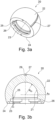
- FIGS 3a and 3b show a joint insert 20 according to the invention.
- the concave joint surface 21 of the joint insert 20 is designed as a nut joint.
- both partial joints are spherical, the radius R Ei of the concave joint surface 21 is larger than the radius of the opening of the receptacle formed by the concave joint surface 21 or the diameter D Pi of the concave articular surface 11 of the acetabulum 10 is larger than the diameter D Po of the acetabulum opening.
- the joint insert 20 in the Figures 3a and 3b is not only designed as a nut joint in the area of the concave joint surface 21, but also has an additional securing device in the form of a recess 26 in the area 25 extending beyond the equator towards the opening of the concave joint surface 21. This recess is provided for the insertion of a securing ring. Consequently, in the embodiment shown, the joint insert 20 on the side of the second partial joint is designed with two securing devices that prevent separation of the convex joint surface 32 of the joint head 30 from the concave joint surface 21 of the joint insert 20. However, it is equally possible to provide only one of the securing devices 25, 26 in order to prevent dislocation of the respective partial joint.
- An elongated strip made of a flexible material is preferably used as the retaining ring.
- the elongated strip is preferably preformed in a C-shape.
- the flexible C-shaped retaining ring is not preformed, it only becomes C-shaped upon insertion into the circumferential recess 26.
- the Figures 3a and 3b shown joint insert 20 has an insertion aid 27 in the form of an elongated groove on the side of the first partial joint, ie on the convex surface 22 of the joint insert 20.
- This groove 27 runs from the circumferential edge 24 of the convex joint surface 22 over the pole 29 back to the circumferential Edge 24.
- the contact points of the groove 27 with the circumferential edge 24 are diametrically opposite in the embodiment shown, since the insertion aid 27 is located in a plane of symmetry of the spherical convex joint surface 22.
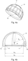
- the joint socket 10 shown which forms the receptacle for the first partial joint, has a spherical segment-shaped, concave joint surface 11 and an outer surface 17 intended for implantation into the bone tissue of a patient.
- the outer surface 17 can be anchored in the bone tissue using various techniques known from the prior art.
- the joint socket 10, as well as the joint insert 20 has a region 12 which, as a safety device, prevents luxation of the first partial joint, i.e., the joint insert 20 from popping out.
- fastening means 18 are provided in the edge region formed between the outer surface 17 and the concave joint surface 11 of the joint socket 10.
- the fastening means 18 are a threaded hole and two locking holes, with the aid of which the joint blocking device 13 from Figure 2 is detachably fastened via a connecting element 14.
- the threaded hole 18 of the joint socket 10 is located on the circumference of the edge area, offset by 90° between the two diametrically opposite locking holes.
- the Figures 5a and 5b show a joint insert 20 according to the invention during insertion into a joint socket 10.
- the joint socket 10 and the joint insert 20 are components of a double mobility hip joint endoprosthesis.
- the joint socket 10 has an inner concave articulating surface 11 that interacts with the convex articulating surface 22 of the joint insert 20.
- the opening of the concave articulating surface 11 of the joint socket 10 is delimited by a circumferential edge 16 and has a diameter that is smaller than the diameter of the concave articulating surface 11 at the equator of the joint socket 10.
- the convex joint surface 22 of the insert 20 has an insertion aid 27, which is located in a plane of symmetry of the insert 20 or the convex joint surface 22.
- the insertion aid 27 shown is designed as an elongated recess that extends from the circumferential edge 24 toward the pole 29 of the convex joint surface 22.
- the elongated recess 27 lies in the plane of symmetry of the convex joint surface 22 indicated by the auxiliary line 28.
- the insertion aid 27 extends to the circumferential edge 24 of the convex surface 22, it is possible to promote the transport of synovial fluid between the convex surface 22 of the insert 27 and the concave surface 11 of the socket 10 as well as the removal of possible wear products between these surfaces and thus to increase the service life of the joint endoprosthesis.
- the elongated recess begins at the peripheral edge 24 of the convex surface 22 and extends into the Figures 5a and 5b over approximately one third of the length of the Auxiliary line 28 between the pole 29 and the edge 24.
- the elongated recess extends over 25% to 75% of the connecting line length.
- the elongated recess does not necessarily have to be in contact with the peripheral edge 24 of the convex surface 22, but can also be arranged with both ends in the convex surface 22 of the joint insert 20.
- the insertion aid 27 can be designed in several parts. This makes it possible to be symmetrical to the Fig. 5a shown insertion aid 27, a further part of the insertion aid 27 is provided on the opposite side of the articular surface 22.
- the shape of the recess is preferably designed to correspond to the contour of the edge of the associated concave joint surface, which serves as the joint partner of the partial joint.
- the recess of the insertion aid 27 With its deepest section, preferably comes into contact with the circumferential edge 16 of the concave receptacle of a joint partner, here the joint socket 10, at least over a section of its recess base.
- the recess 27 has a profile in its longitudinal direction with a radius that is essentially equal to the radius R Pi of the joint socket 10 at its circumferential edge 16.
- the insertion aid 27 preferably gradually transitions into the convex surface of the insert at least at one of its ends in the longitudinal direction.
- the cross-section of the elongated recess is designed to prevent the occurrence of stress peaks in the area of the transition from the insertion aid 27 to the articulating surface 22. For this reason, the insertion aid preferably transitions smoothly into the convex articulating surface 22 of the articulating insert 20.
- the recess-shaped insertion aid 27 is arranged on the auxiliary line 28 between the edge of the convex joint surface 22 and its pole 29.
- the plane formed by the recess forms an angle of 0° with the plane spanned by the auxiliary line 28.
- the angle between the insertion aid 27 and the auxiliary line 28 can be between 0° and 90°, but preferably 0° to 45° and even more preferably 0° to 15°.
- Such a free positioning of the insertion aid 27 on the convex surface 22 of the insert 20 enables optimization with regard to a simple assembly of the joint insert 20 in a joint socket 10 or of a joint head 30 in a joint insert 20.
- the load on the joint that is still caused despite the insertion aid 27 Implant material must be taken into account during assembly of the artificial joint.
- the insertion aid 27 makes it possible to manufacture the joint socket 10 and, in particular, the joint insert 20 or the joint head 30 from a relatively inelastic material, such as metal or ceramic.
- the insertion aid 27 is arranged on the auxiliary line 28, i.e., in a plane of symmetry of the joint insert 20, and thus at an angle of 0°, the joint insert 20 is inserted into the joint socket 10 by tilting the two components approximately 90° relative to each other before insertion. If the insertion aid 27 is arranged at a different angle, the joint socket 10 and the joint insert 20 must be aligned differently for assembly.
- the insertion aid 27 is placed on the circumferential edge 26 of the concave joint socket surface 11 such that the circumferential edge 16 is arranged within the recess of the insertion aid 27.
- the insert 20 is located in the plane of the opening of the concave joint surface 11 in a position slightly offset relative to the assembled state and thus fits through the opening formed by the concave joint surface 11. In other words, the offset compensates for the excess of the joint insert 20 relative to the opening of the joint socket 10.
- the joint insert 20 fits into the concave joint surface 11 of the joint socket 10, since the diameter of the joint insert 20 is at the level of the circumferential edge 24 of the convex surface 22 of the joint insert 20 is smaller than or equal to the diameter of the circumferential edge 16 of the concave joint surface 11 due to the depth of the insertion aid 27.
- connection insert 20 is shown in a slightly inclined position after successful insertion into the joint socket 10. Furthermore, it can be seen that the joint insert 20 of this embodiment has a concave joint surface 21 which is designed to receive a joint head 30 (see Figure 2 ) is provided.
- the present invention provides a dislocation-free joint endoprosthesis that nevertheless allows for easy assembly during a surgical procedure.
Landscapes
- Health & Medical Sciences (AREA)
- Orthopedic Medicine & Surgery (AREA)
- Transplantation (AREA)
- Vascular Medicine (AREA)
- Oral & Maxillofacial Surgery (AREA)
- Engineering & Computer Science (AREA)
- Biomedical Technology (AREA)
- Heart & Thoracic Surgery (AREA)
- Cardiology (AREA)
- Life Sciences & Earth Sciences (AREA)
- Animal Behavior & Ethology (AREA)
- General Health & Medical Sciences (AREA)
- Public Health (AREA)
- Veterinary Medicine (AREA)
- Physical Education & Sports Medicine (AREA)
- Prostheses (AREA)
Description
- Die vorliegende Erfindung betrifft einen Gelenkersatz mit zwei Teilgelenken sowie eine Einsetzhilfe für diesen Gelenkersatz.
- Das Ersetzen eines verletzten oder abgenutzten natürlichen Gelenks mit einem künstlichen Gelenk ist ein alltäglicher Eingriff. So gibt es mittlerweile künstlichen Gelenkersatz für eine Vielzahl von natürlichen Gelenken, wie zum Beispiel für das Hüftgelenk, das Schultergelenk, das Ellenbogengelenk, das Sprunggelenk, das Fingergelenk oder das Kniegelenk. Ein vollständiger bzw. totaler Gelenkersatz besteht dabei aus mindestens zwei Komponenten, die an den sich gegenüberliegenden Knochen fixiert werden. So weisen deartige vollständige Hüftendoprothesen eine Gelenkpfanne auf, die im Acetabulum eines Patienten implantiert wird, sowie einen Gelenkkopf auf einem Prothesenschaft zur Verankerung im Femur.
- Im Allgemeinen werden künstliche Gelenke in Bezug auf ihre Abmessungen und ihren Aufbau nicht einfach den natürlichen Gelenken nachgeahmt. So sind zum Beispiel bei künstlichen Hüftgelenken im Verhältnis zum natürlichen Gelenkkopf die Gelenkköpfe häufig mit einem wesentlich kleineren Durchmesser versehen. Gründe hierfür sind ein verminderter Abrieb oder der Einsatz von Keramik als Prothesenwerkstoff. Bei dem Einsatz einer Keramik haben kleinere Köpfe aufgrund ihres kleineren Volumens den Vorteil, dass das Risiko eines Versagens durch herstellungsbedingte Fehler reduziert wird. Weiter verursachen Gelenkköpfe mit einem kleineren Durchmesser aufgrund der geringeren Bewegung im Gelenkspalt einen geringeren Abrieb. Dagegen haben Gelenkköpfe mit größerem Durchmesser den Vorteil, dass sie eine höhere Stabilität sowie ein geringeres Luxationsrisiko aufweisen und dem Patienten einen größeren Bewegungsumfang bieten.
- Doppelgelenkige Prothesen versuchen, diese sich in Bezug auf den größeren Gelenkkopfdurchmesser ergebenden Vorteile in einer Prothese mit einem kleinen Gelenkkopf umzusetzen. Derartige Hüftendoprothesen umfassen im Regelfall drei Komponenten, die relativ zueinander beweglich sind. Im Vergleich zu den oben genannten Standardprothesen befindet sich zwischen der Hüftpfanne und dem Hüftkopf ein Gelenkeinsatz, der sich relativ zu der Hüftpfanne und dem Hüftkopf bewegen kann. Folglich kombiniert eine solche Hüftendoprothese im Prinzip eine Gelenkprothese mit großem Durchmesser und eine Gelenkprothese mit kleinem Durchmesser, im Folgenden auch als erstes bzw. großes Teilgelenk und zweites bzw. kleines Teilgelenk bezeichnet.
- Das große Gelenk wird von der konkaven Fläche der Hüftpfanne und der konvexen Fläche des Gelenkeinsatzes ausgebildet, während das kleine Gelenk aus der konkaven Fläche des Gelenkeinsatzes und der konvexen Fläche des Hüftkopfes, gebildet wird, der üblicherweise mit einem in einem Femur verankerten Prothesenschaft verbunden ist.
- Dieser mehrgelenkige Aufbau hat zur Folge, dass das Bewegungsausmaß auf das große Gelenk und das kleine Gelenk aufgeteilt wird. Dabei führt das kleine Gelenk vor allem Bewegungen aus, die nur einen kleinen Bewegungsumfang erfordern, wie zum Beispiel der normale Gang. Erreicht das kleine Gelenk allerdings seinen maximalen Ausschlag, so wird spätestens dann auch das große Gelenk ausgelenkt und somit der mögliche Bewegungsumfang der gesamten Hüftgelenkendoprothese ausgenutzt.
- Bei so einem Bewegungsablauf wird also einerseits das Bewegungsausmaß des großen Gelenks minimiert, während die Vorteile eines großen Bewegungsumfangs und eines geringeren Luxationsrisikos beibehalten werden. Andererseits findet bevorzugt ein Großteil der Gelenkbewegung zwischen den Laufflächen des kleinen Gelenks statt, was zu einem insgesamt geringen Verschleiß der Hüftendoprothese beiträgt.
- Damit allerdings ein Zusammenhalt derartig aufgebauter Hüftendoprothesen sichergestellt ist, wird eine der gelenkigen Verbindungen als Nussgelenk ausgeführt. Ein solches Nussgelenk zeichnet sich dadurch aus, dass die konvexe Gelenkfläche des Gelenkkopfes über seinen Äquator hinaus von der konkaven Gelenkfläche der Gelenkpfanne eingefasst ist, sodass einem Auseinanderfallen dieser Komponenten vorgebeugt ist. Ein solches Nussgelenk sollte allerdings intraoperativ montierbar sein, da ein bereits montiertes Gelenk die Implantation erschwert und beim Einschlagen des Gelenks womöglich sogar Schäden auftreten könnten.
- Um einen Gelenkkopf in die gegenüberliegende Gelenkpfanne einzusetzen, damit die konvexe Gelenkfläche mit der konkaven Gelenkfläche in Kontakt kommt, kann der Kopf in den Gelenkeinsatz einschnappbar ausgeführt sein. Hierfür ist allerdings ein gewisser Kraftaufwand notwendig, um den Gelenkkopf bzw. die Öffnung der Pfanne soweit zu verformen, dass der Kopf in der Pfanne zum Sitzen kommt.
- Eine andere Möglichkeit der Montage eines solchen Gelenks wird von der
US Patentanmeldung 2010/0234963 A1 vorgeschlagen, bei welcher die Öffnung der konkaven Fläche der Pfanne so ausgebildet ist, dass der Hüftkopf nur um 90° verdreht durch diese geführt werden kann. Einmal eingeführt, lässt sich der Hüftkopf wieder zurückdrehen, sodass die Pfanne und der Kopf zueinander ausgerichtet sind. Allerdings befindet sich der Rand des Hüftkopfes in einem derartig ausgestalteten Gelenksystem im eingesetzten Zustand zwangsläufig unterhalb der Pfannenöffnung. Damit hat eine solche Anordnung den Nachteil, dass sie eine geometrisch bedingte Einschränkung des Bewegungsumfangs nach sich zieht, da der mit dem Hüftkopf verbundene Implantatschaft früher an den Rand der Pfannenöffnung stößt. - Die Lehre dieses Dokuments beschäftigt sich dabei allerdings nicht mit dem altersbedingten Luxationsrisiko. So ist bei älteren Patienten das Luxationsrisiko neben der operationsbedingten Dehnung und Beschädigung ihres Gewebes zusätzlich erhöht, da es im Regelfall von vornherein geschwächt ist. Dies ist insbesondere dann der Fall, wenn der Implantation eines Gelenksersatzes eine längere Phase eingeschränkter Mobilität aufgrund des verbrauchten Gelenks vorausgegangen ist. Zwar kann diese Situation durch physiotherapeutische Maßnahmen präoperativ verbessert werden, jedoch ist es wünschenswert, weitere Behandlungsmöglichkeiten für derartige Patienten zur Verfügung zu haben, welche die begrenzten Möglichkeiten dieser physiotherapeutischen Maßnahmen ergänzen können.
- Aus der
WO 02/00141 A1 - Aus der
US 2014/128988 sind prothetische Hüftköpfe, bewegliche Einsätze und Hüftpfannenkomponenten vorbekannt, die die Beeinträchtigung von Weichgewebe verringern, den Implantatverschleiß reduzieren und/oder das Reibungsdrehmoment verringern können. Es werden modulare Verbindungen bereitgestellt, die das Auftreten von Lockerungen und Mikrobewegungen minimieren können, die an modularen Verbindungen von orthopädischen Implantaten auftreten können. - Aufgabe der vorliegenden Erfindung war es somit, einen Einsatz und ein Gelenksystem bereitzustellen, das auch bei Patienten mit eingeschränkter Konstitution eine Luxation verhindert. Eine weitere Aufgabe war es, eine einfache intraoperative Montage zu ermöglichen, ohne dabei die Funktionalität der Gelenkendoprothese einzuschränken. Dabei sollte die Belastung der Gelenkkomponenten möglichst niedrig gehalten werden.
- Diese Aufgabe wird durch die in den unabhängigen Ansprüchen definierte Kombination von Merkmalen gelöst. Die zugehörigen abhängigen Ansprüche beschreiben dabei bevorzugte Ausführungsformen der vorliegenden Erfindung.
- Zur Lösung der Aufgabe stellt die vorliegende Erfindung einen Gelenkersatz gemäß Anspruch 1.
- Die Sicherungseinrichtungen der Gelenkpfanne und des Gelenkeinsatzes ermöglichen es, das Luxationsrisiko insbesondere bei Patienten mit geschwächtem Gewebe zu minimieren oder sogar auszuschließen. Somit können auch Patienten einen Gelenkersatz erhalten, bei denen ein solcher aufgrund des Gewebezustands zuvor nur schwer oder nicht möglich war. Die damit wiedergewonnene Bewegungsfreiheit bedeutet für diese Patienten einen erheblichen Zugewinn an Lebensqualität.
- Bei einer besonders bevorzugten Ausführungsform der vorliegenden Erfindung, beugt ein Bereich der konkaven Gelenkfläche der Gelenkpfanne und/oder des Gelenkeinsatzes der Luxation des jeweiligen Teilgelenks durch Ausbilden des jeweiligen Gelenks als Nussgelenk vor.
- Die Sicherungseinrichtungen des erfindungsgemäßen Gelenkersatzes sind also so ausgeführt, dass die Teilgelenke auch ohne äußere Krafteinwirkung im montierten Zustand verbleiben, ohne dass dabei ihre Bewegungsfreiheit eingeschränkt wird.
- Der Zusammenhalt der Gelenkkomponenten wird dadurch gewährleistet, dass die Einsatzöffnung des aufnehmenden Gelenkteils kleiner ist als die Außenabmessung des einzusetzenden Gelenkteils. Anders ausgedrückt ist die Einsatzöffnung der konkaven Gelenkfläche so ausgebildet, dass sie kleiner ist als der größte Abstand zwischen zwei Punkten auf der konvexen Fläche des Einsatzes, zumindest wenn es sich dabei um ein Kugelgelenk handelt. Folglich befindet sich der Bereich, welcher einer Luxation vorbeugt, bei der umlaufenden Kante der konkaven Gelenkfläche. Unter der Annahme einer Kugelform des Gelenks bildet der Bereich somit den Teil der Gelenkfläche aus, der über deren Äquator hinausgeht.
- Bei einer weiteren bevorzugten Ausführungsform ist der Öffnungsdurchmesser der konkaven Gelenkfläche 1% bis 6%, bevorzugt 2% bis 5%, am bevorzugtesten 3,5% bis 5% geringer als der Gelenkdurchmesser.
- Hierdurch kann einer Luxation des im Patienten implantierten Gelenks effektiv vorgebeugt bzw. diese verhindert werden. Dabei ist es insbesondere bei den unteren Werten dieser Bereiche möglich, die Gelenkpartner durch Einpressen des männlichen Gelenkteils in das weibliche Gelenkteil zu montieren. Dabei sollte jedoch zumindest einer der Gelenkpartner möglichst aus einem Polymer, insbesondere UHMWPE, hergestellt sein. Dabei kann das Einpressen vor der Implantation des Gelenkersatzes erfolgen, um eine Beschädigung des Patientengewebes zu vermeiden.
- Bei einer besonders bevorzugten Ausführungsform weist die Sicherungseinrichtung von zumindest einem der Teilgelenke zwei bevorzugt lösbare Sicherungselemente auf, die zusammenwirkend einer Luxation des Teilgelenks vorbeugen.
- Anders als bei der oben beschriebenen Montage des Gelenks durch Zusammenpressen kann die Montage des Gelenks mithilfe der Sicherungselemente auch bei der Implantation erfolgen. Mit anderen Worten ist bei dem erfindungsgemäßen Gelenkersatz bevorzugt nur eines der Teilgelenke als Nussgelenk ausgeführt, das durch Zusammenpressen der beiden Gelenkkomponenten montiert wird. Zumindest das andere Teilgelenk sollte bei dieser Ausführungsform hingegen, insbesondere wenn es als Nussgelenk ausgebildet ist, mit Hilfe von lösbaren Sicherungselementen montierbar sein. Diese ermöglichen, den oben erwähnte Bereich der konkaven Gelenkfläche, welcher das Gelenk als Nussgelenk ausbildet, erst nach dem Einsetzen des konvexen Gelenkpartners mit der konkaven Gelenkfläche zu verbinden.
- Dass zumindest eines der Teilgelenke mit einer lösbare Sicherungselemente aufweisenden Sicherungseinrichtung ausgebildet ist, hat zudem im Falle einer Reversion Vorteile, da hierdurch eine Entnahme der auszutauschenden Gelenkkomponenten vereinfacht wird.
- Bei einer weiteren besonders bevorzugten Ausführungsform wirken die zwei Sicherungselemente mittels einer bevorzugt lösbaren Schraub-, Verriegelungs- und/oder Schnappverbindung zusammen.
- Die so ausgeführte Sicherungseinrichtung ist einfach montierbar und kann zudem auch lösbar ausgeführt sein.
- Beispielsweise kann die Sicherungseinrichtung in Form einer Schraubverbindung ausgebildet sein, da diese einfach montierbar und auch leicht wieder lösbar ist. Um einem ungewollten Lösen der Sicherungseinrichtung dieser Ausführungsform vorzubeugen, ist diese bevorzugt über einen Form- oder Reibschluss mit einem Blockierelement gesichert.
- Bei einer weiteren Ausführungsform der vorliegenden Erfindung ist ein Sicherungselement durch eine bevorzugt umlaufende Aussparung zur Aufnahme eines Sicherungsrings in der konkaven Gelenkfläche der Gelenkpfanne und/oder des Gelenkeinsatzes ausgebildet.
- Bei dieser Ausführungsform kann aufgrund der Verwendung eines Sicherungsrings bei der Montage jegliche Belastung auf das Gewebe vermieden werden. Ähnliches kann auch für eine Schnappverbindung gelten, die über einen Sicherungsring gesichert wird.
- Als Sicherungsring wird bevorzugt ein länglicher Streifen aus einem flexiblen Material verwendet, der noch bevorzugter als C-förmiger Ring vorgeformt ist. Der Streifen ist über eine Zugangsöffnung oder -aussparung, die sich vom Rand der konkaven Gelenkfläche bis zu der umlaufenden Aussparung erstreckt, der Länge nach in die Aussparung einführbar.
- Bei einer weiteren erfindungsgemäßen Ausführungsform ist ein Sicherungselement durch mindestens eine Aussparung in der Gelenkpfanne und/oder in dem Gelenkeinsatz ausgebildet, welches mit einem Vorsprung eines weiteren Sicherungselements als Bajonettverbindung wirkt.
- Wie bereits oben im Zusammenhang mit dem Gewinde beschrieben, ist auch diese Sicherungseinrichtung einfach montierbar und lösbar. Der Vorteil dieser Ausführungsform liegt darin, dass mit einem Bajonettverschluss die Verriegelung der Sicherheitselemente sowohl durch Ausübung einer Kraft wie auch eines Moments erfolgt und so die Belastung des Gewebes beispielweise gegenüber einem reinen Moment zur Montage des Gelenks verringert werden kann.
- Die Einsetzhilfe kann selbstverständlich bei dem ersten und/oder dem zweiten Teilgelenk zum Einsatz kommen, d. h. auch oder alternativ zwischen dem Gelenkeinsatz und der konvexen Fläche des Gelenkkopfes.
- Die Einsetzhilfe hat insbesondere bei einer Ausbildung eines Teilgelenks als Nussgelenk, das ohne Einsetzhilfe nur durch Zusammenpressen der Gelenkteile vor der Implantation zusammengesetzt werden sollte, den Vorteil, dass die Einpresskraft vermindert oder sogar vermieden wird. Gleichzeitig wird eine Luxation des Gelenks im Bereich des möglichen Bewegungsumfangs des implantierten Gelenks verhindert. Folglich kann mit Hilfe einer Einsetzhilfe ein Teilgelenk intraoperativ montiert werden, das ansonsten nur vor der Implantation zusammengesetzt werden könnte. Hierdurch kann das Luxationsrisiko bei den im Alltag vorkommenden Belastungen ausgeschlossen werden.
- Die zum Montieren des Teilgelenks notwendige Verformung wird dadurch vermindert oder umgangen, dass die Aussparung mit ihrer bevorzugt länglichen Form den Durchmesser der konvexen Gelenkfläche partiell reduziert. Dank der Einsetzhilfe ist der notwendige Kraftaufwand beim Einsetzen in die konkave Gelenkfläche des Nussgelenks, wenn überhaupt vorhanden, so gering, dass insbesondere intraoperativ die Belastung für das Gewebe des Patienten reduziert sowie einer Beschädigung der Gelenkkomponenten vorgebeugt wird.
- Die auf der Gleitfläche angeordnete längliche Aussparung der Einsetzhilfe ermöglicht ein erleichtertes Einsetzen der konvexen Gelenkfläche in die konkave Gelenkfläche des jeweiligen Teilgelenks. Je nach Dimensionierung der Aussparung kann dieses Einsetzen ohne jegliche Verformung oder mit einer Verformung ausgeführt werden, die lediglich Spannungen verursacht, bei denen keine Beschädigungen der Materialien der Gelenkpfanne bzw. des Einsatzes auftreten. Folglich ist es mit diesem Einsatz möglich, einen Überdeckungsgrad des Nussgelenks zu erreichen, der höher ist als der, welcher durch ein Einsetzen mittels einer Schnappverbindung erreicht werden kann. Zudem beugt die Aussparung beim Einsetzen einem unkontrollierten Wegrutschen bei der Montage vor, wie es beispielsweise bei einer Schnappverbindung auftreten kann.
- Die längliche Form der Einsetzhilfe auf der konvexen Gelenkfläche hat insbesondere den Vorteil, dass die Einsetzhilfe so der Kontur der Öffnungskante der konkaven Gelenkfläche angepasst werden kann. Zudem wird auf diese Weise sichergestellt, dass die Einsetzhilfe aufgrund ihrer minimalen Größe einen möglichst geringen Einfluss auf die Geometrie der konvexen Fläche des Einsatzes aufweist.
- Für das Einsetzen der konvexen Gelenkkomponente mit Hilfe der Einsetzhilfe werden die beiden Gelenkpartner relativ zueinander geneigt. Um eine Luxation zu verursachen, müsste folglich das Gelenk zum gleichen Ausmaß wie beim Einsetzen ausgelenkt werden. Durch das Platzieren der Einsetzhilfe in einer Symmetrieebene der konvexen Gelenkfläche wird unabhängig von der Ausrichtung des Gelenks nach Implantation erreicht, dass das Teilgelenk um nahezu 90° ausgelenkt werden müsste, um eine Luxation zu verursachen. Eine derartige Auslenkung ist, insbesondere beim Hüftgelenk, physiologisch im Regelfall weder physiologisch noch aufgrund des Prothesenhalses erreichbar.
- Eine noch höhere Absicherung gegen eine Luxation ist möglich, wenn die Ausrichtung der Einsetzhilfe im implantierten Zustand berücksichtigt wird. Mit anderen Worten wird die Einsetzhilfe so auf der konvexen Gelenkfläche des Teilgelenks positioniert, dass sie nach der Implantation durch den physiologischen Bewegungsumfang nicht erreicht werden kann. Beispielsweise ist es von Vorteil, bei einem Hüftgelenk die Einsetzhilfe hinter dem Bereich der maximalen Adduktion zu platzieren.
- Auch wenn die Einsetzhilfe vor allem bei einem Doppelgelenk von Vorteil ist, um einer Luxation vorzubeugen, können die oben genannten Vorteile mit den entsprechenden Merkmalen auch bei einem einfachen Nussgelenk erreicht werden.
- Mit Hilfe der folgenden Figuren und Beschreibung werden Ausführungsbeispiele für ein besseres Verständnis der vorliegenden Erfindung im Detail beschrieben. Hierfür wurden die in den Figuren ersichtlichen Merkmale mit Bezugszeichen gekennzeichnet. Dabei wurden bei unterschiedlichen Ausführungsbeispiele gleiche Bezugszeichen verwendet, sofern sich die Merkmale in diesen Ausführungsbeispielen gleichen oder eine gleiche Wirkung erzielen.
-
Figur 1 zeigt einen erfindungsgemäßen montierten Gelenkersatz, der zwei Teilgelenke aufweist. -
Figur 2 zeigt einen erfindungsgemäßen als Nussgelenk ausgeführten Gelenkeinsatz während des Einsetzens eines an einem Prothesenschaft montierten Gelenkkopfes. - Die
Figuren 3a und 3b zeigen einen erfindungsgemäßen Einsatz, der auf seiner konvexen Gelenkfläche eine Einsetzhilfe aufweist. - Die
Figuren 4a und 4b zeigen eine erfindungsgemäße implantierbare Gelenkpfanne. - Die
Figuren 5a und 5b zeigen das Einsetzen eines erfindungsgemäßen Gelenkeinsatzes mittels einer länglich ausgeführten Einsetzhilfe. -
Figur 1 zeigt den montierten Zustand einer doppelgelenkigen Hüftendoprothese, die auch als Double Mobility Prothese bezeichnet wird. Derartige Prothesen aus dem Stand der Technik ermöglichen, wie oben bereits beschrieben, trotz eines kleinen Hüftkopfes 3 den Bewegungsumfang einer Großkopfprothese. Das inFigur 1 in der Abduktionsstellung gezeigte Implantat kombiniert dabei die Vorteile geringeren Abriebs eines kleineren Hüftkopfes mit dem größeren Bewegungsumfang einer Großkopfprothese, indem es über zwei Teilgelenke aufgebaut ist. - Das erste Teilgelenk befindet sich zwischen der im Beckenknochen implantierten Hüftpfanne 1 und einem Gelenkeinsatz 2. Das zweite Teilgelenk wird zwischen dem Gelenkeinsatz 2 und dem Hüftkopf 3 ausgebildet. Wie durch die Auslenkung des Implantats mit maximalem Abduktionswinkel in
Figur 1 erkennbar, vergrößert sich der Bewegungsumfang dadurch, dass der unter dem Hüftkopf 3 befindliche Prothesenschaft 4 zwar an den Rand des Gelenkeinsatzes 2 stößt, dieser jedoch durch die Beweglichkeit des ersten Teilgelenks ausgelenkt wird, sodass der Bewegungsumfang bis zum Anschlag des Prothesenschaft 4 an den inneren Rand der Hüftpfanne 3 vergrößert wird. - Bei dem in
Figur 1 gezeigten Implantat weist das erste Teilgelenk zwischen der Hüftpfanne 1 und dem Gelenkeinsatz 2 Gelenkkomponenten eines Kugelgelenks auf, die auseinanderfallen, wenn sie nicht durch äußere Kräfte zusammengehalten werden. Hingegen handelt es sich bei dem zweiten Teilgelenk zwischen dem Gelenkeinsatz 2 und dem Hüftkopf 3 um ein Nussgelenk. Bei diesem Gelenk umschließt der Gelenkeinsatz 2 den Hüftkopf 3 über dessen Äquator hinaus und ist folglich so an diesem montiert, dass die beiden Gelenkkomponenten des zweiten Teilgelenks auch ohne äußere stabilisierende Krafteinwirkung nicht auseinanderfallen. -
Figur 2 zeigt eine erfindungsgemäße Hüftendoprothese beim Einsetzen des Hüftkopfes 30 in den Gelenkeinsatz 20. Dabei wird der mit dem Prothesenschaft 40 verbundene Gelenkkopf 30 mithilfe eines Drückwerkzeugs 50 in die konkave Gelenkfläche 21 des Gelenkeinsatzes 20 eingesetzt. Eine Gelenkblockiereinrichtung 13 stellt beim Einpressen des Gelenkkopfes 30 über die umlaufende Kante 23 der konkaven Fläche 21 des Gelenkeinsatzes 20 sicher, dass der Gelenkeinsatz 20 während der Verwendung des Werkzeugs 50 nicht relativ zu der Gelenkpfanne 10 verschwenken kann. Dazu ist die Gelenkblockiereinrichtung 13 wie weiter unten beschrieben über ein Verbindungselement 14 an dem Rand 15 der Gelenkpfanne 10 gesichert, der sich zwischen der Außenfläche 17 der Gelenkpfanne 10 und der konkaven Innenfläche 11 der Gelenkpfanne befindet bzw. diese verbindet. So befestigt, erstreckt sich ein Abschnitt der Gelenkblockiereinrichtung über den Rand des Gelenkeinsatzes 20, der sich zwischen der umlaufenden Kante 23 der konkaven Gelenkfläche 21 und der umlaufenden Kante 24 der konvexen Gelenkfläche 22 befindet. Vorteilhafterweise erstreckt sich der Abschnitt der Gelenkblockiereinrichtung 13 dabei um über mehr als 180° des ringförmigen Rands des Gelenkeinsatzes 20, um ein Ausdrehen des Gelenkeinsatzes in allen Richtungen zu unterbinden. - Selbstverständlich ist es möglich, auch für den Gelenkkopf 30 eine derartige Gelenkblockiereinrichtung 13 vorzusehen, um das Einsetzen des Gelenkkopfes 30 in die konkave Gelenkfläche 21 des Gelenkeinsatzes 20 zu erleichtern.
- Wenn die Montage eines oder beider Teilgelenke nach Implantation der Gelenkpfanne durchgeführt wird, kann die Gelenkblockiereinrichtung 13 zudem so ausgelegt sein, dass das Drückwerkzeug 50 diese als Widerlager verwendet. Bei so einer Ausführung stützt sich das Drückwerkzeug an der Blockiereinrichtung 13 ab, sodass bestenfalls keine Kraft auf das umliegende Knochengewebe ausgeübt wird.
- Weiterhin ist in
Figur 2 zu erkennen, dass der Rand des Gelenkeinsatzes 20 in seiner neutralen Position, d.h. die Rotationssymmetrieachse des Gelenkeinsatzes 20 und der Gelenkpfanne 10 liegen aufeinander, mit dem Rand 15 der Gelenkpfanne 20 fluchtet. Genauso ist es möglich, den umlaufenden Rand des Gelenkeinsatzes 20 in Bezug auf den Rand 15 der Gelenkpfanne 20 in neutraler Position bzw. Ausgangsposition hervorstehen zu lassen. Damit lässt sich bei gleichbleibendem Bewegungsumfang die Bewegungshäufigkeit zwischen der Gelenkpfanne 10 und dem Gelenkeinsatz 20 erhöhen. Anders gesagt, kommt es bei einer Auslenkung des Gelenkkopfes 30 früher zu einer Berührung des Prothesenschafts 40 mit dem umlaufenden Rand des Gelenkeinsatzes 20 und damit früher zu einer aufgezwungenen Relativbewegung zwischen dem Einsatz 20 und der Gelenkpfanne 10. Da dies, wie oben beschrieben, einen erhöhten Abrieb zur Folge haben kann, wird die inFigur 2 gezeigte Ausführungsform bevorzugt. - Die
Figuren 3a und 3b zeigen einen erfindungsgemäßen Gelenkeinsatz 20. Wie inFigur 3b zu erkennen, ist die konkave Gelenkfläche 21 des Gelenkeinsatzes 20 als Nussgelenk ausgebildet. Gleiches gilt für die konkave Gelenkfläche 11 in der inFigur 4b gezeigten Schnittansicht der Gelenkpfanne 10. Folglich weist die konkave Aufnahme bei beiden Teilgelenken eine Einsetzöffnung auf, die kleiner ist als die in ihr aufzunehmende konvexe Gelenkfläche, sodass die Montage der Teilgelenke Kraftaufwand und/oder eine Einsetzhilfe 27 erfordert. - Da in dem in den
Figuren 3 und4 gezeigten Ausführungsbeispiel beide Teilgelenke kugelförmig ausgebildet sind, ist der Radius REi der konkaven Gelenkfläche 21 größer als der Radius der Öffnung der durch die konkave Gelenkfläche 21 ausgebildeten Aufnahme bzw. ist der Durchmesser DPi der konkaven Gelenkfläche 11 der Gelenkpfanne 10 größer als der Durchmesser DPo der Gelenkpfannenöffnung. - Der Gelenkeinsatz 20 in den
Figuren 3a und 3b ist im Bereich der konkaven Gelenkfläche 21 nicht nur als Nussgelenk ausgeführt, sondern weist in dem über den Äquator hinausgehenden Bereich 25 hin zur Öffnung der konkaven Gelenkfläche 21 zudem eine zusätzliche Sicherungseinrichtung in Form einer Aussparung 26 auf. Diese ist für das Einsetzen eines Sicherungsrings vorgesehen. Folglich ist bei dem gezeigten Ausführungsbeispiel der Gelenkeinsatz 20 auf der Seite des zweiten Teilgelenks mit zwei Sicherungseinrichtungen ausgeführt, die einer Trennung der konvexen Gelenkfläche 32 des Gelenkkopfes 30 von der konkaven Gelenkfläche 21 des Gelenkeinsatzes 20 vorbeugen. Allerdings ist es genauso möglich, nur eine der Sicherungseinrichtungen 25, 26 vorzusehen, um eine Luxation des jeweiligen Teilgelenks zu verhindern. - Als Sicherungsring wird bevorzugt ein länglicher Streifen aus einem flexiblen Material verwendet. Vorzugsweise ist der längliche Streifen C-förmig vorgeformt. Zum Einführen des Sicherungsrings in die umlaufende Aussparung 26, wird er durch eine Zugangsöffnung oder Zugangsaussparung, die vom Rand einer konkaven Gelenkfläche 11, 21 zu der Aussparung 26 verläuft, der Länge nach in die Aussparung 26 hineingeschoben. Ist der flexible C-förmige Sicherungsring nicht vorgeformt, wird dieser erst durch das Einführen in die umlaufende Aussparung 26 C-förmig. Alternativ ist es auch möglich, einen Sprengring als Sicherungsring zu verwenden.
- Weiterhin weist der in den
Figuren 3a und 3b gezeigte Gelenkeinsatz 20 auf der Seite des ersten Teilgelenks, d.h. auf der konvexen Fläche 22 des Gelenkeinsatzes 20 eine Einsetzhilfe 27 in Form einer länglichen Nut auf. Diese Nut 27 verläuft von der umlaufenden Kante 24 der konvexen Gelenkfläche 22 über den Pol 29 wieder zu der umlaufenden Kante 24. Die Berührungspunkte der Nut 27 mit der umlaufenden Kante 24 liegen sich im gezeigten Ausführungsbeispiel diametral gegenüber, da sich die Einsetzhilfe 27 in einer Symmetrieebene der kugelförmigen konvexen Gelenkfläche 22 befindet. - Die in den
Figuren 4a und 4b gezeigte Gelenkpfanne 10, welche die Aufnahme für das erste Teilgelenk ausbildet, weist eine kugelsegmentförmige konkave Gelenkfläche 11 auf sowie eine für die Implantation in das Knochengewebe eines Patienten vorgesehene Außenfläche 17. Die Außenfläche 17 kann über verschiedene aus dem Stand der Technik bekannte Techniken in dem Knochengewebe verankert werden. Wie oben bereits beschrieben, weist die Gelenkpfanne 10 wie auch der Gelenkeinsatz 20 einen Bereich 12 auf, der als Sicherungseinrichtung eine Luxation des ersten Teilgelenk, d.h. ein Herausspringen des Gelenkeinsatzes 20, verhindert. - Weiterhin sind in dem Randbereich, der zwischen der Außenfläche 17 und der konkaven Gelenkfläche 11 der Gelenkpfanne 10 ausgebildet ist, Befestigungsmittel 18 vorgesehen. Bei den Befestigungsmitteln 18 handelt es sich bei dem vorliegenden Ausführungsbeispiel um ein Gewindeloch und zwei Arretierungslöcher, mit Hilfe derer die Gelenkblockiereinrichtung 13 aus
Figur 2 über ein Verbindungselement 14 lösbar befestigt wird. Wie denFiguren 2 und4 zu entnehmen ist, befindet sich das Gewindeloch 18 der Gelenkpfanne 10 dabei auf dem Umfang des Randbereichs jeweils um 90° versetzt zwischen den zwei diametral gegenüberliegenden Arretierungslöchern. - Nachfolgend wird anhand der
Figuren 5a und 5b erläutert, wie eine Einsetzhilfe 27 das Einsetzen eines Gelenkeinsatzes 20 in eine Gelenkpfanne 10 unterstützt. Allerdings lässt sich das Folgende wie auch das Vorhergehende ohne weiteres auch auf das Teilgelenk übertragen, das von der konkaven Gelenkfläche 21 des Gelenkeinsatzes 20 und der konvexen Gelenkfläche 32 des Gelenkkopfes 30 gebildet wird. - Die
Figuren 5a und 5b zeigen einen erfindungsgemäßen Gelenkeinsatz 20 während des Einsetzens in eine Gelenkpfanne 10. Bei dem vorliegenden Ausführungsbeispiel sind die Gelenkpfanne 10 und der Gelenkeinsatz 20 Komponenten einer Double Mobility Hüftgelenkendoprothese. Die Gelenkpfanne 10 weist eine innere konkave Gelenkfläche 11 auf, die mit der konvexen Gelenkfläche 22 des Gelenkeinsatzes 20 zusammenwirkt. Die Öffnung der konkaven Gelenkfläche 11 der Gelenkpfanne 10 ist durch eine umlaufende Kante 16 begrenzt und weist einen Durchmesser auf, der kleiner ist als der Durchmesser der konkaven Gelenkfläche 11 auf der Höhe des Äquators der Gelenkpfanne 10. - Wie weiterhin in den
Figuren 5a und 5b zu erkennen ist, weist die konvexe Gelenkfläche 22 des Einsatzes 20 eine Einsetzhilfe 27 auf, die sich in einer Symmetrieebene des Einsatzes 20 bzw. der konvexen Gelenkfläche 22 befindet. Die gezeigte Einsetzhilfe 27 ist als längliche Aussparung ausgeführt, die sich von der umlaufenden Kante 24 in Richtung des Pols 29 der konvexen Gelenkfläche 22 erstreckt. Die längliche Aussparung 27 liegt in der durch die Hilfslinie 28 angedeuteten Symmetrieebene der konvexen Gelenkfläche 22. - Dadurch, dass sich die Einsetzhilfe 27 bis an die umlaufende Kante 24 der konvexen Fläche 22 erstreckt, ist es möglich, den Transport von Gelenkflüssigkeit zwischen der konvexen Fläche 22 des Einsatzes 27 und der konkaven Fläche 11 der Pfanne 10 als auch den Abtransport möglicher Abriebprodukte zwischen diesen Flächen zu fördern und somit die Lebensdauer der Gelenkendoprothese zu erhöhen.
- Die längliche Aussparung beginnt an der umlaufenden Kante 24 der konvexen Fläche 22 und erstreckt sich in den
Figuren 5a und 5b über ungefähr ein Drittel der Länge der Hilfslinie 28 zwischen dem Pol 29 und der Kante 24. Die längliche Aussparung erstreckt sich über 25 % bis 75 % der Verbindungslinienlänge. - Es versteht sich, dass die längliche Aussparung nicht zwangsläufig mit der umlaufenden Kante 24 der konvexen Fläche 22 in Berührung sein muss, sondern ebenso mit beiden Enden in der konvexen Fläche 22 des Gelenkeinsatzes 20 angeordnet sein kann. Weiterhin kann die Einsetzhilfe 27 mehrteilig ausgeführt sein. So ist es möglich symmetrisch zu der in
Fig. 5a gezeigten Einsetzhilfe 27 einen weiteren Teil der Einsetzhilfe 27 auf der gegenüberliegenden Seite der Gelenkfläche 22 vorzusehen. - Je länger und breiter die Einsetzhilfe 27 ausgeführt wird, desto einfacher kann der Gelenkeinsatz 20 in eine als Nussgelenk ausgeführte Gelenkpfanne 10 eingesetzt werden. Es ist jedoch zu beachten, dass bei ansteigender Länge bzw. Breite die konvexe Fläche des Einsatzes unregelmäßiger wird, was ein lokales Ansteigen von Spannungen mit sich ziehen kann.
- Die Form der Aussparung ist vorzugsweise korrespondierend zu der Kontur der Kante der zugehörigen konkaven Gelenkfläche, die als Gelenkpartner des Teilgelenks dient, ausgeführt. Dabei kommt die Aussparung der Einsetzhilfe 27 mit ihrem tiefsten Abschnitt beim Anlegen an der Gelenkpfanne 10 bevorzugt zumindest über einen Abschnitt ihres Aussparungsbodens mit der umlaufenden Kante 16 der konkaven Aufnahme eines Gelenkpartners, hier der Gelenkpfanne 10, in Berührung. Am bevorzugtesten weist die Aussparung 27 in ihrer Längsrichtung ein Profil mit einem Radius auf, der im Wesentlichen dem Radius RPi der Gelenkpfanne 10 bei ihrer umlaufenden Kante 16 gleicht. Dabei geht die Einsetzhilfe 27 bevorzugt zumindest an einem ihrer Enden in Längsrichtung graduell in die konvexe Fläche des Einsatzes über.
- Der Querschnitt der länglichen Aussparung ist so ausgeführt, um das Entstehen von Spannungsspitzen im Bereich des Übergangs von der Einsetzhilfe 27 zu der Gelenkfläche 22 zu vermeiden. Aus diesem Grund geht die Einsetzhilfe bevorzugt fließend in die konvexe Gelenkfläche 22 des Gelenkeinsatzes 20 über.
- Bei der gezeigten Ausführungsform ist die aussparungsförmige Einsetzhilfe 27 auf der Hilfslinie 28 zwischen dem Rand der konvexen Gelenkfläche 22 und deren Pol 29 angeordnet. Mit anderen Worten bildet die durch die Aussparung ausgebildete Ebene mit der durch die Hilfslinie 28 aufgespannten Ebene einen Winkel von 0°. Auch wenn dies die bevorzugte Ausführungsform ist, so ist es ohne weiteres möglich, einen beliebigen anderen Winkel zu wählen.
- Mit anderen Worten kann der Winkel zwischen der Einsetzhilfe 27 und der Hilfslinie 28 zwischen 0° bis 90° betragen, jedoch bevorzugt 0° bis 45° und noch bevorzugter 0° bis 15°. Im Allgemeinen gilt der Grundsatz, dass je kleiner der Winkel zwischen der Einsetzhilfe 27 und der gedachten Hilfslinie 28, desto geringer ist die Wahrscheinlichkeit, dass sich die Einsetzhilfe 27 während der auftretenden Bewegung des Gelenks in Flucht mit der Öffnungskante der Gelenkpfanne begibt, sodass es zu einer Luxation kommen kann.
- Alternativ ist es möglich, die durch die Einsetzhilfe 27 aufgespannte Ebene parallel zu der durch die Hilfslinie 28 aufgespannten Ebene bzw. der Symmetrieebene der konvexen Gelenkfläche 22 zu versetzen.
- Eine derart freie Positionierung der Einsetzhilfe 27 auf der konvexen Fläche 22 des Einsatzes 20 ermöglicht eine Optimierung hinsichtlich einer einfachen Montage des Gelenkeinsatzes 20 in einer Gelenkpfanne 10 oder eines Gelenkkopfes 30 in einem Gelenkeinsatz 20. So kann die trotz der Einsetzhilfe 27 noch hervorgerufene Belastung des Implantatmaterials bei der Montage des künstlichen Gelenks berücksichtigt werden. Auch ist es möglich, eine Materialbelastung der Gelenkpfanne 10, des Einsatzes 20 und/oder des Gelenkkopfes 30 in Abhängigkeit vom Implantationsort und den sich daraus ergebenden Belastungen zu reduzieren. Somit ist es durch die Einsetzhilfe 27 möglich, die Gelenkpfanne 10 und insbesondere den Gelenkeinsatz 20 bzw. den Gelenkkopf 30 aus einem relativ unelastischen Material herzustellen, wie zum Beispiel Metall oder Keramik.
- Da bei der gezeigten Ausführungsform die Einsetzhilfe 27 auf der Hilfslinie 28, d. h. in einer Symmetrieebene des Gelenkeinsatzes 20, und damit in einem Winkel von 0° angeordnet ist, erfolgt das Einsetzen des Gelenkeinsatzes 20 in die Gelenkpfanne 10, indem die beiden Komponenten vor dem Einsetzen um in etwa 90° zueinander geneigt werden. Ist die Einsetzhilfe 27 in einem anderen Winkel angeordnet, so müssen die Gelenkpfanne 10 und der Gelenkeinsatz 20 für die Montage entsprechend anders zueinander ausgerichtet werden.
- Nach dem Ausrichten wird die Einsetzhilfe 27 auf die umlaufende Kante 26 der konkaven Gelenkpfannenfläche 11 gesetzt, sodass die umlaufende Kante 16 innerhalb der Aussparung der Einsetzhilfe 27 angeordnet ist. Auf diese Weise befindet sich der Einsatz 20 in der Ebene der Öffnung der konkaven Gelenkfläche 11 in einer relativ zum montierten Zustand leicht versetzten Position und passt so durch die von der konkaven Gelenkfläche 11 ausgebildeten Öffnung. Anders ausgedrückt gleicht der Versatz das Übermaß des Gelenkeinsatzes 20 im Verhältnis zu der Öffnung der Gelenkpfanne 10 aus.
- Mit anderen Worten passt der Gelenkeinsatz 20 in die konkave Gelenkfläche 11 der Gelenkpfanne 10, da der Durchmesser des Gelenkeinsatzes 20 auf der Höhe der umlaufenden Kante 24 der konvexen Fläche 22 des Gelenkeinsatzes 20 aufgrund der Tiefe der Einsetzhilfe 27 kleiner oder gleich dem Durchmesser der umlaufenden Kante 16 der konkaven Gelenkfläche 11 ist.
- In
Figur 5b wird der Gelenkeinsatz 20 nach erfolgreichem Einsetzen in die Gelenkpfanne 10 in leichter Schrägstellung gezeigt. Weiterhin ist zu erkennen, dass der Gelenkeinsatz 20 dieses Ausführungsbeispiels eine konkave Gelenkfläche 21 aufweist, die für die Aufnahme eines Gelenkkopfes 30 (sieheFigur 2 ) vorgesehen ist. - In jedem Fall wird durch die vorliegende Erfindung eine luxationsfreie Gelenkendoprothese bereitgestellt, die dennoch einen einfachen Zusammenbau während eines operativen Eingriffs ermöglicht.
-
- 1
- Hüftpfanne (Stand der Technik)
- 2
- Gelenkeinsatz (Stand der Technik)
- 3
- Gelenkkopf (Stand der Technik)
- 4
- Gelenkschaft (Stand der Technik)
- 10
- Gelenkpfanne
- 11
- konkave Gelenkfläche der Gelenkpfanne
- 12
- Sicherungseinrichtung der Gelenkpfanne: Vorsprung
- 13
- Gelenkblockiereinrichtung
- 14
- Verbindungselement
- 15
- umlaufender Rand der Gelenkpfanne
- 16
- umlaufende Kante der Gelenkpfanne
- 17
- Außenfläche der Gelenkpfanne
- 18
- Befestigungsmittel
- 20
- Gelenkeinsatz
- 21
- konkave Gelenkfläche des Gelenkeinsatzes
- 22
- konvexe Gelenkfläche des Gelenkeinsatzes
- 23
- umlaufende Kante der konkaven Gelenkfläche des Gelenkeinsatzes
- 24
- umlaufende Kante der konvexen Gelenkfläche des Gelenkeinsatzes
- 25
- Sicherungseinrichtung des Gelenkeinsatzes: Vorsprung
- 26
- Sicherungseinrichtung des Gelenkeinsatzes: Aussparung für Sicherungsring
- 27
- Einsetzhilfe: Aussparung
- 28
- Hilfslinie auf der konvexen Gelenkfläche des Gelenkeinsatzes 20, die in dessen Symmetrieebene verläuft
- 29
- Pol der konvexen Gelenkfläche 22
- 30
- Gelenkkopf
- 32
- konvexe Gelenkfläche des Gelenkkopfes
- 40
- Prothesenschaft
- 50
- Drückwerkzeug
- Aq
- Äquator einer konvexen bzw. konkaven Gelenkfläche
- RPi
- innerer Radius der Gelenkpfanne
- DPi
- Gelenkinnendurchmesser der Gelenkpfanne
- DPo
- Gelenköffnungsdurchmesser der Gelenkpfanne
- REi
- innerer Radius des Gelenkeinsatzes
- DEo
- Gelenkinnendurchmesser des Gelenkeinsatzes
- DEi
- Gelenköffnungsdurchmesser des Gelenkeinsatzes
Claims (8)
- Gelenkersatz miteiner Gelenkpfanne (10), die eine konkave Gelenkfläche (11) aufweist, einem Gelenkkopf (30), der eine konvexe Gelenkfläche (32) aufweist, die durch eine umlaufende Kante begrenzt ist, undeinem Gelenkeinsatz (20), der eine konkave (21) und eine konvexe Gelenkfläche (22) aufweist, die jeweils durch eine umlaufende Kante (23, 24) begrenzt sind,wobei die konvexe Gelenkfläche (22) des Gelenkeinsatzes (20) ausgelegt ist, um im montierten Zustand mit der konkaven Gelenkfläche (11) der Gelenkpfanne (10) ein erstes Teilgelenk auszubilden,die konkave Gelenkfläche (21) des Gelenkeinsatzes (20) ausgelegt ist, um im montierten Zustand mit der konvexen Gelenkfläche (32) des Gelenkkopfes (30) ein zweites Teilgelenk auszubilden unddie Gelenkpfanne (10) und der Gelenkeinsatz (20) jeweils eine Sicherungseinrichtung (12, 25, 26) aufweisen, die einer Luxation des Gelenkersatzes vorbeugt,wobei der Gelenkkopf (30) und/oder der Gelenkeinsatz (20) eine Einsetzhilfe (27, 28) aufweist, mit der das Einsetzen der jeweiligen konvexen Gelenkfläche (22, 32) in die dazugehörige konkave Gelenkfläche (11, 21) ermöglicht wird,dadurch gekennzeichnet, dass die Einsetzhilfe (27) als eine längliche Aussparung in der konvexen Gelenkfläche (22, 32) von zumindest einem der Teilgelenke ausgebildet ist, wobei die längliche Aussparung an der umlaufenden Kante (24) der konvexen Gelenkfläche (22, 32) beginnt und sich über 25 % bis 75 % der Länge einer Hilfslinie (28) erstreckt, die auf der konvexen Gelenkfläche (22, 32) in dessen Symmetrieebene zwischen der umlaufenden Kante (24) und einem Pol (29) der Gelenkfläche (22, 32) verläuft.
- Gelenkersatz nach Anspruch 1,
bei dem ein Bereich (12, 25) der konkaven Gelenkfläche (11, 21) der Gelenkpfanne (10) und/oder des Gelenkeinsatzes (20) der Luxation des jeweiligen Teilgelenks durch Ausbilden des jeweiligen Gelenks als Nussgelenk vorbeugt. - Gelenkersatz nach Anspruch 2,
bei dem der Öffnungsdurchmesser (DPo, DEo) der konkaven Gelenkfläche (11, 21) 1% bis 6%, bevorzugt 2% bis 5%, am bevorzugtesten 3,5% bis 5% geringer ist als der Gelenkdurchmesser (DPi,DEi). - Gelenkersatz nach Anspruch 2 oder 3,
bei dem die Sicherungseinrichtung (12, 25, 26) von zumindest einem der Teilgelenke zwei bevorzugt lösbare Sicherungselemente aufweist, die zusammenwirkend einer Luxation des Teilgelenks vorbeugen. - Gelenkersatz nach Anspruch 4,
bei dem die zwei Sicherungselemente mittels einer bevorzugt lösbaren Schraub-, Verriegelungs- und/oder Schnappverbindung zusammenwirken. - Gelenkersatz nach einem der Ansprüche 4 oder 5,
bei dem ein Sicherungselement durch eine bevorzugt umlaufende Aussparung (26) zur Aufnahme eines Sicherungsrings in der konkaven Gelenkfläche (11, 21) der Gelenkpfanne (10) und/oder des Gelenkeinsatzes (20) ausgebildet ist. - Gelenkersatz nach einem der Ansprüche 4 bis 6,
bei dem ein Sicherungselement durch mindestens eine Aussparung in der Gelenkpfanne (10) und/oder in dem Gelenkeinsatz (20) ausgebildet ist, welches mit einem Vorsprung eines weiteren Sicherungselements eine Bajonettverbindung ausbildet. - Gelenkersatz nach einem der vorstehenden Ansprüche,
bei dem die Einsetzhilfe (27) in der Symmetrieebene der konvexen Gelenkfläche (22, 32) ausgebildet ist.
Applications Claiming Priority (2)
| Application Number | Priority Date | Filing Date | Title |
|---|---|---|---|
| DE201520100029 DE202015100029U1 (de) | 2015-01-07 | 2015-01-07 | Double mobility prothese |
| PCT/EP2015/079419 WO2016110372A1 (de) | 2015-01-07 | 2015-12-11 | Double mobility prothese |
Publications (2)
| Publication Number | Publication Date |
|---|---|
| EP3242633A1 EP3242633A1 (de) | 2017-11-15 |
| EP3242633B1 true EP3242633B1 (de) | 2025-03-26 |
Family
ID=52812257
Family Applications (1)
| Application Number | Title | Priority Date | Filing Date |
|---|---|---|---|
| EP15808221.4A Active EP3242633B1 (de) | 2015-01-07 | 2015-12-11 | Double mobility prothese |
Country Status (7)
| Country | Link |
|---|---|
| US (1) | US10952860B2 (de) |
| EP (1) | EP3242633B1 (de) |
| CN (1) | CN107205826B (de) |
| AR (1) | AR104364A1 (de) |
| DE (1) | DE202015100029U1 (de) |
| ES (1) | ES3029235T3 (de) |
| WO (1) | WO2016110372A1 (de) |
Citations (1)
| Publication number | Priority date | Publication date | Assignee | Title |
|---|---|---|---|---|
| US20140128988A1 (en) * | 2012-09-27 | 2014-05-08 | The General Hospital Corporation D/B/A Massachusetts General Hospital | Femoral heads, mobile inserts, acetabular components, and modular junctions for orthopedic implants and methods of using femoral heads, mobile inserts, acetabular components, and modular junctions for orthopedic implants |
Family Cites Families (13)
| Publication number | Priority date | Publication date | Assignee | Title |
|---|---|---|---|---|
| US4619658A (en) * | 1982-02-24 | 1986-10-28 | Pappas Michael J | Spherical kinematic joint |
| US4642123A (en) | 1983-03-08 | 1987-02-10 | Joint Medical Products Corporation | Ball and socket bearing for artificial joint |
| US4714477A (en) * | 1986-08-08 | 1987-12-22 | Dow Corning Wright Corporation | Ball-and-socket joint prosthesis with bearing insert |
| FR2685630A1 (fr) * | 1991-12-27 | 1993-07-02 | Impact | Noyau de cotyle pour prothese de hanche. |
| FR2795302B1 (fr) | 1999-06-23 | 2001-12-28 | Rech S Et De Fabrication S E R | Prothese totale de la hanche |
| FR2807315B1 (fr) * | 2000-04-06 | 2003-01-17 | Rech S Et De Fabrication S E R | Insert cotyloidien pour prothese totale de la hanche |
| FR2810878B1 (fr) * | 2000-06-30 | 2003-08-08 | Henry Graf | Prothese articulee |
| ATE387161T1 (de) | 2001-01-25 | 2008-03-15 | Smith & Nephew Inc | Rückhaltevorrichtung zum halten eines prosthetischen bestandteils |
| DE102005006316A1 (de) * | 2005-02-11 | 2006-08-24 | Nowakowski, Andrej, Dr. med. Dipl.-Ing.(FH) | Hüftgelenk-Endoprothesensystem |
| GB0521406D0 (en) * | 2005-10-20 | 2005-11-30 | Benoist Girard Sas | Total hip prosthesis |
| FR2948013B1 (fr) * | 2009-07-16 | 2012-11-16 | Rech S Et De Fabrication Serf Soc Et | Cupule metallique pour implant cotyloidien |
| US8398718B2 (en) * | 2011-02-16 | 2013-03-19 | Rodney Ian Walter Richardson | Acetabular cup with rotatable bearing member |
| US20140303743A1 (en) * | 2013-03-15 | 2014-10-09 | Sambhu Choudhury | Inner acetabular liner for a dual mobility femoral head construct |
-
2015
- 2015-01-07 DE DE201520100029 patent/DE202015100029U1/de not_active Expired - Lifetime
- 2015-12-11 WO PCT/EP2015/079419 patent/WO2016110372A1/de not_active Ceased
- 2015-12-11 ES ES15808221T patent/ES3029235T3/es active Active
- 2015-12-11 US US15/541,898 patent/US10952860B2/en not_active Expired - Fee Related
- 2015-12-11 CN CN201580072585.0A patent/CN107205826B/zh not_active Expired - Fee Related
- 2015-12-11 EP EP15808221.4A patent/EP3242633B1/de active Active
-
2016
- 2016-01-06 AR ARP160100022A patent/AR104364A1/es active IP Right Grant
Patent Citations (1)
| Publication number | Priority date | Publication date | Assignee | Title |
|---|---|---|---|---|
| US20140128988A1 (en) * | 2012-09-27 | 2014-05-08 | The General Hospital Corporation D/B/A Massachusetts General Hospital | Femoral heads, mobile inserts, acetabular components, and modular junctions for orthopedic implants and methods of using femoral heads, mobile inserts, acetabular components, and modular junctions for orthopedic implants |
Also Published As
| Publication number | Publication date |
|---|---|
| CN107205826B (zh) | 2020-07-14 |
| US10952860B2 (en) | 2021-03-23 |
| US20180008420A1 (en) | 2018-01-11 |
| EP3242633A1 (de) | 2017-11-15 |
| CN107205826A (zh) | 2017-09-26 |
| AR104364A1 (es) | 2017-07-19 |
| DE202015100029U1 (de) | 2015-03-19 |
| ES3029235T3 (en) | 2025-06-23 |
| WO2016110372A1 (de) | 2016-07-14 |
Similar Documents
| Publication | Publication Date | Title |
|---|---|---|
| EP1642552B1 (de) | Endoprothese für ein Metatarsophalangealgelenk | |
| DE69729058T2 (de) | Modulares Stabilisierungs- und Vergrösserungssystem für Gelenkprothese | |
| EP1959871B1 (de) | Facettengelenkprothese | |
| EP2328518B1 (de) | Kniearthrodese- implantat | |
| EP0079441B1 (de) | Endoprothese zum Ersatz stabförmiger Knochen | |
| DE112004001893B4 (de) | Kegelförmige Gelenksprothese | |
| EP2394606A1 (de) | Prothese zum teilweisen Ersatz eines Röhrenknochens | |
| DE8304914U1 (de) | Kugelförmiges kinematisches Gelenk | |
| DE202005020876U1 (de) | Endoprothese für ein Schultergelenk | |
| DE4442206A1 (de) | Gelenkprothese | |
| EP2213262B1 (de) | Kniegelenkendoprothese | |
| EP1845901A2 (de) | Hüftgelenk-endoprothesensystem | |
| DE2810748A1 (de) | Kuenstliches gelenk fuer gliedmassen | |
| EP2066265A2 (de) | Hüftimplantat und modul für hüftimplantat | |
| WO2013060718A1 (de) | Adapter für ein implantat und kniegelenkprothese | |
| EP2662055A1 (de) | Verstärkungsimplantat für einen langgestreckten Knochen, insbesondere Femur | |
| EP3228280B1 (de) | Am beckenknochen montierbare abstützvorrichtung | |
| DE102004008138B4 (de) | Femurkomponente für eine Hüftgelenks-Endoprothese | |
| EP3242633A1 (de) | Double mobility prothese | |
| EP3498230A1 (de) | Modulares endoprothesen-schaftsystem mit rotationselement | |
| EP4252715A1 (de) | Femurimplantat und femurimplantat-set | |
| DE102005001255B4 (de) | Inverse Schultergelenk-Endoprothese mit einteiligem Mittelteil | |
| DE102022000228A1 (de) | Rotationsadaptiver Knochenmarknagel | |
| DE102024102123A1 (de) | Ellbogen Arthrodese-Implantat mit verbesserter anatomischer Anpassbarkeit | |
| DE102015202715B4 (de) | Gelenkinterimsprothese |
Legal Events
| Date | Code | Title | Description |
|---|---|---|---|
| STAA | Information on the status of an ep patent application or granted ep patent |
Free format text: STATUS: THE INTERNATIONAL PUBLICATION HAS BEEN MADE |
|
| PUAI | Public reference made under article 153(3) epc to a published international application that has entered the european phase |
Free format text: ORIGINAL CODE: 0009012 |
|
| STAA | Information on the status of an ep patent application or granted ep patent |
Free format text: STATUS: REQUEST FOR EXAMINATION WAS MADE |
|
| 17P | Request for examination filed |
Effective date: 20170619 |
|
| AK | Designated contracting states |
Kind code of ref document: A1 Designated state(s): AL AT BE BG CH CY CZ DE DK EE ES FI FR GB GR HR HU IE IS IT LI LT LU LV MC MK MT NL NO PL PT RO RS SE SI SK SM TR |
|
| AX | Request for extension of the european patent |
Extension state: BA ME |
|
| DAV | Request for validation of the european patent (deleted) | ||
| DAX | Request for extension of the european patent (deleted) | ||
| STAA | Information on the status of an ep patent application or granted ep patent |
Free format text: STATUS: EXAMINATION IS IN PROGRESS |
|
| 17Q | First examination report despatched |
Effective date: 20190513 |
|
| GRAP | Despatch of communication of intention to grant a patent |
Free format text: ORIGINAL CODE: EPIDOSNIGR1 |
|
| STAA | Information on the status of an ep patent application or granted ep patent |
Free format text: STATUS: GRANT OF PATENT IS INTENDED |
|
| INTG | Intention to grant announced |
Effective date: 20241104 |
|
| GRAS | Grant fee paid |
Free format text: ORIGINAL CODE: EPIDOSNIGR3 |
|
| GRAA | (expected) grant |
Free format text: ORIGINAL CODE: 0009210 |
|
| STAA | Information on the status of an ep patent application or granted ep patent |
Free format text: STATUS: THE PATENT HAS BEEN GRANTED |
|
| AK | Designated contracting states |
Kind code of ref document: B1 Designated state(s): AL AT BE BG CH CY CZ DE DK EE ES FI FR GB GR HR HU IE IS IT LI LT LU LV MC MK MT NL NO PL PT RO RS SE SI SK SM TR |
|
| REG | Reference to a national code |
Ref country code: GB Ref legal event code: FG4D Free format text: NOT ENGLISH |
|
| REG | Reference to a national code |
Ref country code: CH Ref legal event code: EP |
|
| REG | Reference to a national code |
Ref country code: DE Ref legal event code: R096 Ref document number: 502015017056 Country of ref document: DE |
|
| REG | Reference to a national code |
Ref country code: IE Ref legal event code: FG4D Free format text: LANGUAGE OF EP DOCUMENT: GERMAN |
|
| REG | Reference to a national code |
Ref country code: SE Ref legal event code: TRGR |
|
| REG | Reference to a national code |
Ref country code: ES Ref legal event code: FG2A Ref document number: 3029235 Country of ref document: ES Kind code of ref document: T3 Effective date: 20250623 |
|
| PG25 | Lapsed in a contracting state [announced via postgrant information from national office to epo] |
Ref country code: RS Free format text: LAPSE BECAUSE OF FAILURE TO SUBMIT A TRANSLATION OF THE DESCRIPTION OR TO PAY THE FEE WITHIN THE PRESCRIBED TIME-LIMIT Effective date: 20250626 |
|
| PG25 | Lapsed in a contracting state [announced via postgrant information from national office to epo] |
Ref country code: FI Free format text: LAPSE BECAUSE OF FAILURE TO SUBMIT A TRANSLATION OF THE DESCRIPTION OR TO PAY THE FEE WITHIN THE PRESCRIBED TIME-LIMIT Effective date: 20250326 |
|
| REG | Reference to a national code |
Ref country code: LT Ref legal event code: MG9D |
|
| PG25 | Lapsed in a contracting state [announced via postgrant information from national office to epo] |
Ref country code: NO Free format text: LAPSE BECAUSE OF FAILURE TO SUBMIT A TRANSLATION OF THE DESCRIPTION OR TO PAY THE FEE WITHIN THE PRESCRIBED TIME-LIMIT Effective date: 20250626 |
|
| PG25 | Lapsed in a contracting state [announced via postgrant information from national office to epo] |
Ref country code: HR Free format text: LAPSE BECAUSE OF FAILURE TO SUBMIT A TRANSLATION OF THE DESCRIPTION OR TO PAY THE FEE WITHIN THE PRESCRIBED TIME-LIMIT Effective date: 20250326 |
|
| PG25 | Lapsed in a contracting state [announced via postgrant information from national office to epo] |
Ref country code: LV Free format text: LAPSE BECAUSE OF FAILURE TO SUBMIT A TRANSLATION OF THE DESCRIPTION OR TO PAY THE FEE WITHIN THE PRESCRIBED TIME-LIMIT Effective date: 20250326 |
|
| PG25 | Lapsed in a contracting state [announced via postgrant information from national office to epo] |
Ref country code: GR Free format text: LAPSE BECAUSE OF FAILURE TO SUBMIT A TRANSLATION OF THE DESCRIPTION OR TO PAY THE FEE WITHIN THE PRESCRIBED TIME-LIMIT Effective date: 20250627 Ref country code: BG Free format text: LAPSE BECAUSE OF FAILURE TO SUBMIT A TRANSLATION OF THE DESCRIPTION OR TO PAY THE FEE WITHIN THE PRESCRIBED TIME-LIMIT Effective date: 20250326 |
|
| REG | Reference to a national code |
Ref country code: NL Ref legal event code: MP Effective date: 20250326 |
|
| PG25 | Lapsed in a contracting state [announced via postgrant information from national office to epo] |
Ref country code: NL Free format text: LAPSE BECAUSE OF FAILURE TO SUBMIT A TRANSLATION OF THE DESCRIPTION OR TO PAY THE FEE WITHIN THE PRESCRIBED TIME-LIMIT Effective date: 20250326 |
|
| PG25 | Lapsed in a contracting state [announced via postgrant information from national office to epo] |
Ref country code: SM Free format text: LAPSE BECAUSE OF FAILURE TO SUBMIT A TRANSLATION OF THE DESCRIPTION OR TO PAY THE FEE WITHIN THE PRESCRIBED TIME-LIMIT Effective date: 20250326 |
|
| PG25 | Lapsed in a contracting state [announced via postgrant information from national office to epo] |
Ref country code: PT Free format text: LAPSE BECAUSE OF FAILURE TO SUBMIT A TRANSLATION OF THE DESCRIPTION OR TO PAY THE FEE WITHIN THE PRESCRIBED TIME-LIMIT Effective date: 20250728 |
|
| PG25 | Lapsed in a contracting state [announced via postgrant information from national office to epo] |
Ref country code: PL Free format text: LAPSE BECAUSE OF FAILURE TO SUBMIT A TRANSLATION OF THE DESCRIPTION OR TO PAY THE FEE WITHIN THE PRESCRIBED TIME-LIMIT Effective date: 20250326 |
|
| PG25 | Lapsed in a contracting state [announced via postgrant information from national office to epo] |
Ref country code: EE Free format text: LAPSE BECAUSE OF FAILURE TO SUBMIT A TRANSLATION OF THE DESCRIPTION OR TO PAY THE FEE WITHIN THE PRESCRIBED TIME-LIMIT Effective date: 20250326 |
|
| PG25 | Lapsed in a contracting state [announced via postgrant information from national office to epo] |
Ref country code: RO Free format text: LAPSE BECAUSE OF FAILURE TO SUBMIT A TRANSLATION OF THE DESCRIPTION OR TO PAY THE FEE WITHIN THE PRESCRIBED TIME-LIMIT Effective date: 20250326 |
|
| PG25 | Lapsed in a contracting state [announced via postgrant information from national office to epo] |
Ref country code: SK Free format text: LAPSE BECAUSE OF FAILURE TO SUBMIT A TRANSLATION OF THE DESCRIPTION OR TO PAY THE FEE WITHIN THE PRESCRIBED TIME-LIMIT Effective date: 20250326 |
|
| PG25 | Lapsed in a contracting state [announced via postgrant information from national office to epo] |
Ref country code: IS Free format text: LAPSE BECAUSE OF FAILURE TO SUBMIT A TRANSLATION OF THE DESCRIPTION OR TO PAY THE FEE WITHIN THE PRESCRIBED TIME-LIMIT Effective date: 20250726 |
|
| REG | Reference to a national code |
Ref country code: DE Ref legal event code: R097 Ref document number: 502015017056 Country of ref document: DE |
|
| PGFP | Annual fee paid to national office [announced via postgrant information from national office to epo] |
Ref country code: GB Payment date: 20251218 Year of fee payment: 11 |
|
| PG25 | Lapsed in a contracting state [announced via postgrant information from national office to epo] |
Ref country code: DK Free format text: LAPSE BECAUSE OF FAILURE TO SUBMIT A TRANSLATION OF THE DESCRIPTION OR TO PAY THE FEE WITHIN THE PRESCRIBED TIME-LIMIT Effective date: 20250326 |
|
| PGFP | Annual fee paid to national office [announced via postgrant information from national office to epo] |
Ref country code: FR Payment date: 20251217 Year of fee payment: 11 |
|
| PGFP | Annual fee paid to national office [announced via postgrant information from national office to epo] |
Ref country code: SE Payment date: 20251217 Year of fee payment: 11 |
|
| PG25 | Lapsed in a contracting state [announced via postgrant information from national office to epo] |
Ref country code: CZ Free format text: LAPSE BECAUSE OF FAILURE TO SUBMIT A TRANSLATION OF THE DESCRIPTION OR TO PAY THE FEE WITHIN THE PRESCRIBED TIME-LIMIT Effective date: 20250326 |
|
| PLBE | No opposition filed within time limit |
Free format text: ORIGINAL CODE: 0009261 |
|
| STAA | Information on the status of an ep patent application or granted ep patent |
Free format text: STATUS: NO OPPOSITION FILED WITHIN TIME LIMIT |
|
| REG | Reference to a national code |
Ref country code: CH Ref legal event code: L10 Free format text: ST27 STATUS EVENT CODE: U-0-0-L10-L00 (AS PROVIDED BY THE NATIONAL OFFICE) Effective date: 20260211 |
|
| 26N | No opposition filed |
Effective date: 20260105 |
|
| PGFP | Annual fee paid to national office [announced via postgrant information from national office to epo] |
Ref country code: ES Payment date: 20260119 Year of fee payment: 11 |
|
| PGFP | Annual fee paid to national office [announced via postgrant information from national office to epo] |
Ref country code: DE Payment date: 20251222 Year of fee payment: 11 |
|
| PGFP | Annual fee paid to national office [announced via postgrant information from national office to epo] |
Ref country code: IT Payment date: 20251231 Year of fee payment: 11 |