EP3242367B1 - Gleichstromschutzschalter - Google Patents
Gleichstromschutzschalter Download PDFInfo
- Publication number
- EP3242367B1 EP3242367B1 EP15875622.1A EP15875622A EP3242367B1 EP 3242367 B1 EP3242367 B1 EP 3242367B1 EP 15875622 A EP15875622 A EP 15875622A EP 3242367 B1 EP3242367 B1 EP 3242367B1
- Authority
- EP
- European Patent Office
- Prior art keywords
- mechanical switch
- circuit breaker
- current
- switching device
- circuit
- Prior art date
- Legal status (The legal status is an assumption and is not a legal conclusion. Google has not performed a legal analysis and makes no representation as to the accuracy of the status listed.)
- Active
Links
- 230000005540 biological transmission Effects 0.000 claims description 49
- 239000003990 capacitor Substances 0.000 claims description 41
- 239000004065 semiconductor Substances 0.000 claims description 22
- 230000002457 bidirectional effect Effects 0.000 claims description 20
- 238000011084 recovery Methods 0.000 claims description 6
- 230000001052 transient effect Effects 0.000 claims description 6
- 238000010586 diagram Methods 0.000 description 6
- 238000000034 method Methods 0.000 description 6
- 238000007792 addition Methods 0.000 description 2
- 238000012986 modification Methods 0.000 description 2
- 230000004048 modification Effects 0.000 description 2
- 238000006467 substitution reaction Methods 0.000 description 2
- 230000015556 catabolic process Effects 0.000 description 1
- 238000010276 construction Methods 0.000 description 1
- 230000000694 effects Effects 0.000 description 1
- 238000005516 engineering process Methods 0.000 description 1
- 238000002347 injection Methods 0.000 description 1
- 239000007924 injection Substances 0.000 description 1
- 239000000243 solution Substances 0.000 description 1
Images


Classifications
-
- H—ELECTRICITY
- H01—ELECTRIC ELEMENTS
- H01H—ELECTRIC SWITCHES; RELAYS; SELECTORS; EMERGENCY PROTECTIVE DEVICES
- H01H33/00—High-tension or heavy-current switches with arc-extinguishing or arc-preventing means
- H01H33/02—Details
- H01H33/59—Circuit arrangements not adapted to a particular application of the switch and not otherwise provided for, e.g. for ensuring operation of the switch at a predetermined point in the ac cycle
- H01H33/596—Circuit arrangements not adapted to a particular application of the switch and not otherwise provided for, e.g. for ensuring operation of the switch at a predetermined point in the ac cycle for interrupting dc
-
- H—ELECTRICITY
- H02—GENERATION; CONVERSION OR DISTRIBUTION OF ELECTRIC POWER
- H02H—EMERGENCY PROTECTIVE CIRCUIT ARRANGEMENTS
- H02H3/00—Emergency protective circuit arrangements for automatic disconnection directly responsive to an undesired change from normal electric working condition with or without subsequent reconnection ; integrated protection
- H02H3/08—Emergency protective circuit arrangements for automatic disconnection directly responsive to an undesired change from normal electric working condition with or without subsequent reconnection ; integrated protection responsive to excess current
- H02H3/087—Emergency protective circuit arrangements for automatic disconnection directly responsive to an undesired change from normal electric working condition with or without subsequent reconnection ; integrated protection responsive to excess current for dc applications
-
- H—ELECTRICITY
- H01—ELECTRIC ELEMENTS
- H01H—ELECTRIC SWITCHES; RELAYS; SELECTORS; EMERGENCY PROTECTIVE DEVICES
- H01H33/00—High-tension or heavy-current switches with arc-extinguishing or arc-preventing means
- H01H33/02—Details
- H01H33/04—Means for extinguishing or preventing arc between current-carrying parts
- H01H33/14—Multiple main contacts for the purpose of dividing the current through, or potential drop along, the arc
- H01H33/143—Multiple main contacts for the purpose of dividing the current through, or potential drop along, the arc of different construction or type
-
- H—ELECTRICITY
- H01—ELECTRIC ELEMENTS
- H01H—ELECTRIC SWITCHES; RELAYS; SELECTORS; EMERGENCY PROTECTIVE DEVICES
- H01H33/00—High-tension or heavy-current switches with arc-extinguishing or arc-preventing means
- H01H33/70—Switches with separate means for directing, obtaining, or increasing flow of arc-extinguishing fluid
- H01H33/7015—Switches with separate means for directing, obtaining, or increasing flow of arc-extinguishing fluid characterised by flow directing elements associated with contacts
- H01H33/7023—Switches with separate means for directing, obtaining, or increasing flow of arc-extinguishing fluid characterised by flow directing elements associated with contacts characterised by an insulating tubular gas flow enhancing nozzle
- H01H33/703—Switches with separate means for directing, obtaining, or increasing flow of arc-extinguishing fluid characterised by flow directing elements associated with contacts characterised by an insulating tubular gas flow enhancing nozzle having special gas flow directing elements, e.g. grooves, extensions
-
- H—ELECTRICITY
- H02—GENERATION; CONVERSION OR DISTRIBUTION OF ELECTRIC POWER
- H02H—EMERGENCY PROTECTIVE CIRCUIT ARRANGEMENTS
- H02H3/00—Emergency protective circuit arrangements for automatic disconnection directly responsive to an undesired change from normal electric working condition with or without subsequent reconnection ; integrated protection
- H02H3/02—Details
- H02H3/021—Details concerning the disconnection itself, e.g. at a particular instant, particularly at zero value of current, disconnection in a predetermined order
Definitions
- the present invention relates to a direct current (DC) circuit breaker and, more particularly, to a DC circuit breaker capable of interrupting fault currents flowing through a DC transmission line in both directions with respect to a mechanical switch when a fault occurs on the DC transmission line.
- DC direct current
- a direct current circuit breaker (DC circuit breaker) is used to interrupt a fault current when a fault occurs on a direct current transmission line used as a high voltage transmission line.
- a direct current transmission line for a high voltage is used as a transmission line for a high voltage of 50 kV or higher of a high voltage direct current (HVDC) transmission system or a transmission line for a medium voltage of 50 kV or lower of a medium voltage direct current (MVDC) distribution system.
- HVDC high voltage direct current
- MVDC medium voltage direct current
- a DC circuit breaker is provided with a relatively inexpensive mechanical switch to interrupt a fault current when a fault occurs on a DC transmission line.
- the mechanical switch is opened to interrupt a fault current, thereby preventing a faulty system from influencing a normal system when a fault occurs in a high voltage direct current (HVDC) transmission system or a medium voltage direct current (MVDC) distribution system.
- HVDC high voltage direct current
- MVDC medium voltage direct current
- Korean Patent No. 1183508 and Japanese Patent Application Publication No. 1984-068128 propose DC circuit breakers that extinguish an arc generated in a mechanical switch using a resonance current.
- the conventional DC circuit breakers in order to interrupt a fault current, an arc generated when the mechanical switch is switched off due to a fault is extinguished using a technology in which the arc is extinguished by making a zero current which is formed by superposing a resonance current (reverse current) on a fault current flowing through the arc in the mechanical switch.
- the conventional DC circuit breakers have a problem that interruption speed is slow because the resonance current is generated through multiple resonance cycles.
- the conventional circuit breaker consists of a single resonance circuit and a single mechanical switch connected together, it is possible to interrupt only a fault current flowing in one direction with respect to the mechanical switch.
- the conventional DC circuit breakers have a problem that they have a high transient recovery voltage (TRV), which is a voltage applied between two contacts of a circuit breaker after a fault current is interrupted.
- TRV transient recovery voltage
- a high TRV is applied between two contacts thereof under a certain circuit condition of a system.
- the DC circuit breaker needs to withstand the TRV so that no current can flow between the contacts thereof.
- conventional DC circuit breakers have a high TRV, a dielectric breakdown between the contacts is likely to occur in the DC circuit breakers. In order to solve this problem, additional measures, such as injection of gas, are required.
- Other conventional circuit breakers are disclosed in the following documents: US2009/201717 A1 , JP2002093294 and DE102011083693 .
- an object of the present invention is to provide a DC circuit breaker that can reliably interrupt a fault current in a mechanical switch even without applying a resonance current to the mechanical switch when opening the mechanical switch in the DC circuit breaker.
- another object of the present invention is to provide a DC circuit breaker capable of interrupting fault currents flowing in both forward and backward directions when a fault occurs at one side or a remaining side thereof.
- a further object of the present invention is to provide a DC circuit breaker capable of lowering a transient recovery voltage (TRV) applied between contacts thereof immediately after the a fault current is interrupted.
- TRV transient recovery voltage
- the present invention provides a DC circuit breaker including: a first mechanical switch installed on a DC transmission line and being opened to interrupt a current in the DC transmission line when a fault occurs at one side of the DC circuit breaker on the DC transmission line; a first diode connected in parallel with the first mechanical switch; a second mechanical switch connected in series with the first mechanical switch and being opened to interrupt a current in the DC transmission line when a fault occurs at the remaining side of the DC circuit breaker on the DC transmission line; a second diode connected in parallel with the second mechanical switch; an LC circuit connected in parallel with the first and second mechanical switches and including a capacitor and a reactor connected in series with each other to induce LC resonance; a first unidirectional switching device, connected in parallel with the LC circuit, for switching a current flowing in one direction, to induce LC resonance; and a bidirectional switching device, connected in series with the LC circuit, for switching currents flowing in both forward and backward directions.
- the bidirectional switching device includes a pair of power semiconductor switches that are turn-on/turn-off controllable, are connected in parallel, and are arranged to be counter to each other, and the first unidirectional switching device includes a power semiconductor switch that is turn-on/turn-off controllable.
- the first unidirectional switching device when a fault occurs at the one side of the DC circuit breaker on the DC transmission line, in a state in which the first mechanical switch is open and the bidirectional switching device is in an OFF state, the first unidirectional switching device is turned on such that the capacitor is charged to a voltage -Vc through LC resonance between the capacitor and the reactor of the LC circuit, and subsequently the first unidirectional switching device is turned off and the first power semiconductor switch of the bidirectional switching device is turned on such that a current is supplied through a closed circuit of the second mechanical switch and the first diode due to the voltage -Vc charged in the capacitor, thereby preventing a current from being supplied to the first mechanical switch.
- opening the first mechanical switch and changing the capacitor to the voltage -Vc through the first unidirectional switching device that is turned on are simultaneously performed, or sequentially performed in this order or in a reverse order.
- a transient recovery voltage (TRV) generated in the first mechanical switch is lowered by a reverse voltage that is applied between terminals of the first mechanical switch due to the current supply to the first diode.
- TRV transient recovery voltage
- the second mechanical switch when a fault occurs at the remaining side of the DC circuit breaker on the DC transmission line, the second mechanical switch is opened and the second power semiconductor switch of the bidirectional switching device is turned on such that a current is supplied through a closed circuit of the first mechanical switch and the second diode due to a voltage +Vc stored in the capacitor, thereby preventing a current from being supplied to the second mechanical switch.
- opening the second mechanical switch and supplying the current through the closed circuit of the first mechanical switch 110 and the second diode using the voltage +Vc stored in the capacitor are simultaneously performed or sequentially performed in this order or a reverse order.
- a TRV generated in the second mechanical switch is lowered by a reverse voltage applied between terminals of the second mechanical switch.
- the DC circuit breaker further includes a second unidirectional switching device connected in parallel with the first unidirectional switching device and switching a current flowing in a reverse direction with respect to the current switched by the first unidirectional switching device to induce LC resonance in the LC circuit.
- the second unidirectional switching device is turned on such that the capacitor is charged to a voltage -Vc through the LC resonance caused by the capacitor and the reactor.
- the DC circuit breaker further includes a resistor installed between a ground and a contact point between the LC circuit and the bidirectional switching device.
- the present invention can reliably interrupt a fault current by easily and rapidly extinguishing an arc when the arc is generated during a switching operation of a mechanical switch provided in a DC circuit breaker
- the DC circuit breaker according to the present invention can interrupt fault currents flowing in both forward and backward directions with a single circuit.
- the DC circuit breaker according to the present invention can lower a transient recovery voltage (TRV) applied between two contacts thereof immediately after a fault current is interrupted, thereby improving operation reliability for interruption of a fault current.
- TRV transient recovery voltage
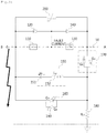
- FIG. 1 is a configuration diagram of a DC circuit breaker according to one embodiment of the present invention.
- a direct current (DC) circuit breaker 100 includes a first mechanical switch 110 installed on a DC transmission line 10 connecting a first side (A side) and a second side (B side) to each other and a second mechanical switch 130 connected in series with the first mechanical switch 110 and installed on the DC transmission line 10.
- the first and second mechanical switches 130 function to block the DC transmission line 10 to prevent a fault current from being supplied to a faulty system when a fault occurs at the first side (A side) or the second side (B side).
- the first mechanical switch 110 and the second mechanical switch 130 are closed in normal condition but opened when a fault occurs.
- the first mechanical switch 110 is opened when a fault occurs at the first side (A side) on the DC transmission line 10, thereby interrupting a current flowing through the DC transmission line 10
- the second mechanical switch 130 is opened when a fault occurs at the second side (B side) on the DC transmission line 10, thereby interrupting a current flowing through the DC transmission line 10.
- Operations of the first and second mechanical switches 110 are controlled by a controller (not shown).
- the DC circuit breaker 100 includes a first diode 120 connected in parallel with the first mechanical switch 110 and a second diode 140 connected in parallel with the second mechanical switch 130.
- the first and second diodes 120 and 140 are formed to operate in counter directions. Specifically, the first diode 120 is formed such that a current is supplied from the A side to the B side but the second diode 140 is formed such that a current is supplied from the B side to the A side.
- the DC circuit breaker 100 further includes an LC circuit 150 connected in parallel with the first and second mechanical switches 110 and 130, a first unidirectional switching device 160 that is connected in parallel with the LC circuit 150 and which switches a current to induce LC resonance, and a bidirectional switching device 170 connected in series with the LC circuit 150 to switch currents flowing in both forward and backward directions.
- the DC circuit breaker 100 may further include a second unidirectional switching device 190 that is connected in parallel with the first unidirectional switching device 160 and which switches a reverse current which is counter to the current switched by the first unidirectional switching device 160 to induce LC resonance in the LC circuit 150.
- the LC circuit 150 includes a capacitor 151 and a reactor 152 connected in series.
- the capacitor 151 and the reactor 152 cause LC resonance in accordance with switching operations of the first unidirectional switching device 160 or the second unidirectional switching device 190.
- the capacitor 151 can be charged in various ways. For example, the capacitor 151 can be charged by a current flowing through the DC transmission line or by an additional charging circuit.
- the bidirectional switching device 170 includes two power semiconductor switches G1 and G2 arranged to be counter to each other and connected in parallel with each other, thereby switching currents flowing in both forward and backward directions.
- the two power semiconductor switches G1 and G2 are arranged to be counter to each other.
- the first and second unidirectional switching devices 160 and 190 respectively include a power semiconductor switch G3 and a power semiconductor switch G4, thereby controlling the flow of a current in a single direction. Although not illustrated in the drawings, switching operations of the power semiconductor switches are controlled by the controller (not shown).
- the power semiconductor switches G1 to G4 are turn-on controllable devices and may be thyristors, for example.
- the power semiconductor switches G1 to G4 are turn-on/turn-off controllable devices and may be gate turn-off thyristors (GTO), insulated gate commutated thyristors (IGCT), or insulated gate bipolar transistors (IGBT), for example.
- GTO gate turn-off thyristors
- IGCT insulated gate commutated thyristors
- IGBT insulated gate bipolar transistors
- a resistor 180 is connected between a ground GND and a contact point between the LC circuit 150 and the bidirectional switching device 170.
- the capacitor 151 of the LC circuit 150 is initially charged to a voltage +Vc through the resistor 160. That is, in initial normal condition, the first and second mechanical switches 110 and 130 are closed and the capacitor 151 is charged to the voltage +Vc by the current flowing through the DC transmission line.
- Charging the capacitor 151 using the resistor 180 is only an example. According to another example, the capacitor 151 may be charged in various ways. For example, the capacitor 151 can be charged using an external power source or an additional charging circuit (not shown).
- a resistor 200 is connected in parallel with the first and second mechanical switches 110 and 130.
- the resistor 200 prevents an overvoltage higher than a rated voltage from being applied between terminals of the DC circuit breaker 100. That is, when a high voltage that is equal to or higher than a predetermined reference voltage is applied between the terminals of the DC circuit breaker 100 due to a certain fault, the high voltage is consumed by the resistor 200.
- the resistor 120 may be a varistor, a surge arrester, or the like.
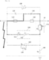
- FIGS. 2A to 2D are schematic diagrams illustrating a fault current interruption process when a fault occurs at one side (A side) of the DC circuit breaker according to the embodiment of the present invention
- FIGS. 3A to 3D are schematic diagrams illustrating a fault current interruption process when a fault occurs at the remaining side (B side) of the DC circuit breaker according to the embodiment of the present invention.
- the first and second mechanical switches 110 and 130 of the DC circuit breaker 100 are closed.
- the unidirectional switching device 160 and the bidirectional switching device 170 are turned off. Therefore, when a voltage is applied to the DC transmission line 10, a normal current flows through the DC transmission line 10 via the first and second mechanical switches 110 and 130, and a current also flows through the capacitor 151 and the reactor 152 of the LC circuit 150 and the resistor 180, whereby the capacitor 151 is charged to the voltage +Vc.
- the controller detects the fault and opens the first mechanical switch 110 to interrupt a fault current in the DC transmission line 10, as illustrated in FIG. 2B .
- the first mechanical switch 110 is opened, an arc is generated between the contacts of the first mechanical switch 110, resulting in a fault current (depicted in a dotted line) continuously flowing from the A side to the B side.
- the pair of power semiconductor switches G1 and G2 of the bidirectional switching device 170 are turned off, and the power semiconductor switch G3 of the first unidirectional switching device 160 is turned on.
- LC resonance occurs between the reactor 152 and the capacitor 151 through the power semiconductor switch G3 of the first unidirectional switching device 160, and, as a result, the capacitor 151 is charged to a voltage -Vc.
- the first unidirectional switching device 160 is turned off, and the first power semiconductor switch G1 of the bidirectional switching device 170 is turned on.
- a current flows along a closed circuit of the first power semiconductor switch G1, the second mechanical switch 130, and the first diode 120. Therefore, the current is not supplied to the first mechanical switch 110.
- the magnitude of the current is determined depending on the capacity of the capacitor 151.
- the first mechanical switch 110 interrupts a current
- a voltage at the A side rapidly rises to be higher than that at the B side.
- the increased voltage at the A side is consumed by the resistor 200 connected in parallel with the first mechanical switch 110.
- the second unidirectional switching device 190 is selectively turned on to induce LC resonance in the LC circuit 150, resulting in the capacitor 151 being charged again to the voltage +Vc.
- the controller (not shown) closes the first mechanical switch 110 to reclose the DC transmission line 10.
- the first mechanical switch 110 is closed to form a closed circuit, in the case in which the fault is not properly fixed or a fault occurs again, the fault current interruption process is performed again.
- the reclosing is possible because the capacitor 151 of the LC circuit 150 is maintained at a charged state (+Vc) after the fault current is interrupted in the first mechanical switch 110.
- the controller detects the fault and opens the second mechanical switch 130 to interrupt a fault current flowing through the DC transmission line 10, as illustrated in FIG. 3B .
- the second mechanical switch 130 is opened, an arc is generated between the contacts of the second mechanical switch 130, so a fault current (depicted in a dotted line) continuously flows from the B side to the A side through the arc.
- the first unidirectional switching device 160 is turned off, and the second power semiconductor switch G2 of the bidirectional switching device 170 is turned on. Therefore, due to the voltage +Vc charged in the capacitor 131, a current flows along a closed circuit including the second power semiconductor switch G2, the second mechanical switch 110, and the second diode 140. That is, the current cannot be supplied to the second mechanical switch 130 that is open.
- the second unidirectional switching device 190 may be selectively turned on to induce LC resonance in the LC circuit 150 so that the capacitor 151 can be recharged to the voltage -Vc.
- the second mechanical switch 130 can be reclosed. That is, when a fault at the A side is fixed, the controller (not shown) closes the second mechanical switch 130, thereby forming a closed circuit in the DC transmission line 10 again. In the case in which a closed circuit is formed by closing the second mechanical switch 130, when the fault is not properly fixed or a fault occurs again at the A side, the above-described process is repeated again.
Landscapes
- Engineering & Computer Science (AREA)
- Power Engineering (AREA)
- Driving Mechanisms And Operating Circuits Of Arc-Extinguishing High-Tension Switches (AREA)
Claims (11)
- Ein Gleichstrom-Schutzschalter, aufweisend:einen ersten mechanischen Schalter (110), der an einer Gleichstromübertragungsleitung installiert ist und geöffnet wird, um einen Strom in der Gleichstromübertragungsleitung zu unterbrechen, wenn ein Fehler auf einer Seite des Gleichstrom-Schutzschalters an der Gleichstromübertragungsleitung auftritt,eine erste Diode (120), die mit dem ersten mechanischen Schalter (110) parallel geschaltet ist,einen zweiten mechanischen Schalter (130), der mit dem ersten mechanischen Schalter (110) in Reihe geschaltet ist und geöffnet wird, um einen Strom in der Gleichstromübertragungsleitung zu unterbrechen, wenn ein Fehler auf der verbleibenden Seite des Gleichstrom-Schutzschalters an der Gleichstromübertragungsleitung auftritt,eine zweite Diode (140), die mit dem zweiten mechanischen Schalter (130) parallel geschaltet ist,einen LC-Schaltkreis (150), der mit dem ersten und dem zweiten mechanischen Schalter (110 und 130) parallel geschaltet ist und einen Kondensator (151) und eine Spule (152) aufweist, die miteinander in Reihe geschaltet sind, um LC-Resonanz zu induzieren,eine erste Unidirektional-Schaltvorrichtung (160), die mit dem LC-Schaltkreis (150) parallel geschaltet ist, zum Schalten eines in eine Richtung fließenden Stroms, um LC-Resonanz zu induzieren, undeine Bidirektional-Schaltvorrichtung (170), die mit der Parallelverbindung aus dem LC-Schaltkreis (150) und der ersten Unidirektional-Schaltvorrichtung (160) in Reihe geschaltet ist, zum Schalten von Strömen, die sowohl in der Vorwärts- als auch in der Rückwärtsrichtung fließen.
- Der Gleichstrom-Schutzschalter gemäß Anspruch 1, wobei die Bidirektional-Schaltvorrichtung (170) ein Paar von Leistungshalbleiterschaltern (G1 und G2) aufweist, die steuerbare Einschalt-/Ausschaltschalter sind, parallel geschaltet sind und einander entgegengesetzt angeordnet sind, und wobei die erste Unidirektional-Schaltvorrichtung (160) einen Leistungshalbleiterschalter (G3) aufweist, der ein steuerbarer Einschalt-/Ausschaltschalter ist.
- Der Gleichstrom-Schutzschalter gemäß Anspruch 2, wobei, wenn ein Fehler auf der einen Seite des Gleichstrom-Schutzschalters an der Gleichstromübertragungsleitung auftritt, in einem Zustand, in dem der erste mechanische Schalter (110) geöffnet ist und die Bidirektional-Schaltvorrichtung (170) in einem AUS-Zustand ist, die erste Unidirektional-Schaltvorrichtung (160) eingeschaltet wird, so dass der Kondensator (151) durch LC-Resonanz zwischen dem Kondensator (151) und der Spule (152) des LC-Schaltkreises (150) auf eine Spannung -Vc geladen wird, und anschließend die erste Unidirektional-Schaltvorrichtung (160) ausgeschaltet wird und der erste Leistungshalbleiterschalter (G1) der Bidirektional-Schaltvorrichtung (170) eingeschaltet wird, so dass ein Strom durch einen geschlossenen Stromkreis des zweiten mechanischen Schalters (130) und der ersten Diode (120) aufgrund der im Kondensator (131) geladenen Spannung -Vc zugeführt wird, wodurch verhindert wird, dass dem ersten mechanischen Schalter (110) ein Strom zugeführt wird.
- Der Gleichstrom-Schutzschalter gemäß Anspruch 3, wobei, wenn ein Fehler auf der einen Seite des Gleichstrom-Schutzschalters an der Gleichstromübertragungsleitung auftritt, das Öffnen des ersten mechanischen Schalters (110) und das Ändern des Kondensators (151) auf die Spannung -Vc durch die eingeschaltete erste Unidirektional-Schaltvorrichtung (160) gleichzeitig oder nacheinander in dieser Reihenfolge oder in einer umgekehrten Reihenfolge durchgeführt werden.
- Der Gleichstrom-Schutzschalter gemäß Anspruch 3, wobei, wenn der ersten Diode (120) ein Strom zugeführt wird, eine im ersten mechanischen Schalter (110) erzeugte Einschwingspannung (TRV) um eine Rückwärtsspannung abgesenkt wird, die zwischen Anschlüssen des ersten mechanischen Schalters (110) aufgrund der Stromversorgung der ersten Diode (120) angelegt wird.
- Der Gleichstrom-Schutzschalter gemäß Anspruch 2, wobei, wenn ein Fehler auf der verbleibenden Seite des Gleichstrom-Schutzschalters an der Gleichstromübertragungsleitung auftritt, der zweite mechanische Schalter (130) geöffnet wird und der zweite Leistungshalbleiterschalter (G2) der Bidirektional-Schaltvorrichtung (170) eingeschaltet wird, so dass ein Strom aufgrund einer im Kondensator (151) gespeicherten Spannung +Vc durch einen geschlossenen Stromkreis des ersten mechanischen Schalters und der zweiten Diode (140) zugeführt wird, wodurch verhindert wird, dass dem zweiten mechanischen Schalter (130) ein Strom zugeführt wird.
- Der Gleichstrom-Schutzschalter gemäß Anspruch 6, wobei, wenn ein Fehler auf der verbleibenden Seite des Gleichstrom-Schutzschalters an der Gleichstromübertragungsleitung auftritt, das Öffnen des zweiten mechanischen Schalters (130) und das Zuführen des Stroms durch den geschlossenen Stromkreis des ersten mechanischen Schalters (110) und der zweiten Diode (140) unter Verwendung der im Kondensator (151) gespeicherten Spannung +Vc gleichzeitig oder nacheinander in dieser Reihenfolge oder in einer umgekehrten Reihenfolge ausgeführt werden.
- Der Gleichstrom-Schutzschalter gemäß Anspruch 6, wobei, wenn der zweiten Diode (140) ein Strom zugeführt wird, eine in dem zweiten mechanischen Schalter (130) erzeugte TRV um eine zwischen Anschlüssen des zweiten mechanischen Schalters (130) angelegte Rückwärtsspannung abgesenkt wird.
- Der Gleichstrom-Schutzschalter gemäß Anspruch 6, ferner aufweisend eine zweite Unidirektional-Schaltvorrichtung (190), die zu der ersten Unidirektional-Schaltvorrichtung (160) parallel geschaltet ist und einen Strom schaltet, der bezüglich des durch die erste Unidirektional-Schaltvorrichtung (160) geschalteten Stroms in einer umgekehrten Richtung fließt, um in dem LC-Schaltkreis (150) LC-Resonanz zu induzieren.
- Der Gleichstrom-Schutzschalter gemäß Anspruch 9, wobei nach dem Unterbrechen eines Fehlerstroms im zweiten mechanischen Schalter (130) die zweite Unidirektional-Schaltvorrichtung (190) eingeschaltet wird, so dass der Kondensator (150) durch die durch den Kondensator (151) und die Spule (152) verursachte LC-Resonanz auf eine Spannung -Vc geladen wird.
- Der Gleichstrom-Schutzschalter gemäß Anspruch 1, ferner aufweisend einen Widerstand (180), der zwischen einer Erde und einem Kontaktpunkt zwischen dem LC-Schaltkreis (150) und der Bidirektional-Schaltvorrichtung (170) installiert ist.
Applications Claiming Priority (2)
| Application Number | Priority Date | Filing Date | Title |
|---|---|---|---|
| KR1020140192741A KR101697623B1 (ko) | 2014-12-29 | 2014-12-29 | Dc 차단기 |
| PCT/KR2015/014294 WO2016108528A1 (ko) | 2014-12-29 | 2015-12-24 | Dc 차단기 |
Publications (3)
| Publication Number | Publication Date |
|---|---|
| EP3242367A1 EP3242367A1 (de) | 2017-11-08 |
| EP3242367A4 EP3242367A4 (de) | 2018-08-22 |
| EP3242367B1 true EP3242367B1 (de) | 2020-02-05 |
Family
ID=56284603
Family Applications (1)
| Application Number | Title | Priority Date | Filing Date |
|---|---|---|---|
| EP15875622.1A Active EP3242367B1 (de) | 2014-12-29 | 2015-12-24 | Gleichstromschutzschalter |
Country Status (4)
| Country | Link |
|---|---|
| US (1) | US10418210B2 (de) |
| EP (1) | EP3242367B1 (de) |
| KR (1) | KR101697623B1 (de) |
| WO (1) | WO2016108528A1 (de) |
Families Citing this family (6)
| Publication number | Priority date | Publication date | Assignee | Title |
|---|---|---|---|---|
| KR101506581B1 (ko) * | 2013-08-14 | 2015-03-27 | 주식회사 효성 | 고전압 dc 차단기 |
| KR101522412B1 (ko) * | 2013-12-26 | 2015-05-26 | 주식회사 효성 | 양방향 직류 차단장치 |
| WO2016042601A1 (ja) * | 2014-09-16 | 2016-03-24 | 三菱電機株式会社 | 風力発電システムおよび直流送電システム |
| KR101688921B1 (ko) * | 2015-06-22 | 2017-01-02 | 주식회사 효성 | Dc 차단기 |
| EP3410454A1 (de) * | 2017-05-31 | 2018-12-05 | ABB Schweiz AG | Elektrisches schaltsystem für gleichstrom |
| GB2579637A (en) * | 2018-12-07 | 2020-07-01 | Eaton Intelligent Power Ltd | Circuit breaker |
Family Cites Families (14)
| Publication number | Priority date | Publication date | Assignee | Title |
|---|---|---|---|---|
| JPS5968128A (ja) | 1982-10-13 | 1984-04-18 | 株式会社日立製作所 | 直流しや断器 |
| JPH0950743A (ja) | 1995-08-08 | 1997-02-18 | Mitsubishi Electric Corp | 直流遮断装置 |
| JP3168883B2 (ja) * | 1995-09-06 | 2001-05-21 | 株式会社日立製作所 | 転流型直流遮断器及びそれを用いた電気鉄道用き電回路 |
| US5793586A (en) * | 1996-10-25 | 1998-08-11 | The United States Of America As Represented By The United States Department Of Energy | Hybrid high direct current circuit interrupter |
| US5892342A (en) * | 1997-04-21 | 1999-04-06 | General Electric Company | Self-test circuit for a shorted diode protection panel in a diesel electric locomotive |
| KR100344056B1 (ko) | 1999-03-17 | 2002-07-22 | 주식회사 포스콘 | 직류 대전류 차단장치 |
| JP3943817B2 (ja) * | 2000-09-18 | 2007-07-11 | 株式会社東芝 | 真空直流遮断器 |
| JP4913761B2 (ja) * | 2007-02-07 | 2012-04-11 | 株式会社ワイ・ワイ・エル | 限流遮断器 |
| KR101183508B1 (ko) | 2008-06-10 | 2012-09-20 | 에이비비 테크놀로지 아게 | Dc 전류 차단기 |
| DE102011083693B3 (de) * | 2011-09-29 | 2013-03-28 | Siemens Aktiengesellschaft | Gleichspannungs-Leitungsschutzschalter |
| KR101483084B1 (ko) * | 2013-01-24 | 2015-01-16 | 한국전기연구원 | 직류 전류 차단 장치 및 방법 |
| CN105580231B (zh) * | 2013-04-09 | 2018-04-17 | Abb技术有限公司 | 断路布置 |
| CN103337851B (zh) | 2013-07-04 | 2015-09-23 | 国家电网公司 | 一种半控型有源注入电流式高压直流断路器及其实现方法 |
| KR101550374B1 (ko) * | 2013-12-31 | 2015-09-04 | 주식회사 효성 | 고전압 dc 차단기 |
-
2014
- 2014-12-29 KR KR1020140192741A patent/KR101697623B1/ko active IP Right Grant
-
2015
- 2015-12-24 EP EP15875622.1A patent/EP3242367B1/de active Active
- 2015-12-24 WO PCT/KR2015/014294 patent/WO2016108528A1/ko active Application Filing
- 2015-12-24 US US15/540,953 patent/US10418210B2/en active Active
Non-Patent Citations (1)
| Title |
|---|
| None * |
Also Published As
| Publication number | Publication date |
|---|---|
| EP3242367A1 (de) | 2017-11-08 |
| KR20160080015A (ko) | 2016-07-07 |
| US10418210B2 (en) | 2019-09-17 |
| EP3242367A4 (de) | 2018-08-22 |
| KR101697623B1 (ko) | 2017-01-18 |
| WO2016108528A1 (ko) | 2016-07-07 |
| US20180019084A1 (en) | 2018-01-18 |
Similar Documents
| Publication | Publication Date | Title |
|---|---|---|
| US10476255B2 (en) | DC circuit breaker | |
| EP3242367B1 (de) | Gleichstromschutzschalter | |
| US10176947B2 (en) | High-voltage DC circuit breaker for blocking DC current | |
| US10176939B2 (en) | High-voltage DC circuit breaker for blocking current flowing through DC lines | |
| EP3035471B1 (de) | Hochspannungs-gleichstrom-schutzschalter | |
| US10395866B2 (en) | High voltage DC circuit breaker | |
| KR101521545B1 (ko) | 고압 직류 전류 차단 장치 및 방법 | |
| US20160322177A1 (en) | Bidirectional direct current circuit breaker | |
| US10672574B2 (en) | DC breaker capable of blocking fault current generated in direct current lines | |
| CN106663557B (zh) | 用于中断直流电流的分离开关 | |
| JP2016213192A (ja) | 直流遮断器 | |
| KR101766229B1 (ko) | 갭 스위치를 이용한 고압 직류 차단 장치 및 방법 | |
| WO2015166600A1 (ja) | 直流遮断装置 | |
| JP2014216056A (ja) | 直流回路遮断装置 | |
| JP6386955B2 (ja) | 直流遮断装置および直流遮断方法 | |
| KR101794945B1 (ko) | Dc 차단기 | |
| KR101802509B1 (ko) | 캐스케이드 하프 브리지 sscb | |
| KR20130127082A (ko) | 고속 차단 스위칭을 위한 sscb 회로 | |
| JP6399848B2 (ja) | 開閉器 | |
| JP2024012743A (ja) | 直流電流遮断装置 |
Legal Events
| Date | Code | Title | Description |
|---|---|---|---|
| STAA | Information on the status of an ep patent application or granted ep patent |
Free format text: STATUS: THE INTERNATIONAL PUBLICATION HAS BEEN MADE |
|
| PUAI | Public reference made under article 153(3) epc to a published international application that has entered the european phase |
Free format text: ORIGINAL CODE: 0009012 |
|
| STAA | Information on the status of an ep patent application or granted ep patent |
Free format text: STATUS: REQUEST FOR EXAMINATION WAS MADE |
|
| 17P | Request for examination filed |
Effective date: 20170627 |
|
| AK | Designated contracting states |
Kind code of ref document: A1 Designated state(s): AL AT BE BG CH CY CZ DE DK EE ES FI FR GB GR HR HU IE IS IT LI LT LU LV MC MK MT NL NO PL PT RO RS SE SI SK SM TR |
|
| AX | Request for extension of the european patent |
Extension state: BA ME |
|
| DAV | Request for validation of the european patent (deleted) | ||
| DAX | Request for extension of the european patent (deleted) | ||
| A4 | Supplementary search report drawn up and despatched |
Effective date: 20180719 |
|
| RIC1 | Information provided on ipc code assigned before grant |
Ipc: H02H 3/087 20060101AFI20180713BHEP Ipc: H02H 3/02 20060101ALN20180713BHEP |
|
| RAP1 | Party data changed (applicant data changed or rights of an application transferred) |
Owner name: HYOSUNG HEAVY INDUSTRIES CORPORATION |
|
| RIC1 | Information provided on ipc code assigned before grant |
Ipc: H02H 3/087 20060101AFI20190604BHEP Ipc: H02H 3/02 20060101ALN20190604BHEP |
|
| GRAP | Despatch of communication of intention to grant a patent |
Free format text: ORIGINAL CODE: EPIDOSNIGR1 |
|
| STAA | Information on the status of an ep patent application or granted ep patent |
Free format text: STATUS: GRANT OF PATENT IS INTENDED |
|
| RIC1 | Information provided on ipc code assigned before grant |
Ipc: H02H 3/02 20060101ALN20190626BHEP Ipc: H02H 3/087 20060101AFI20190626BHEP |
|
| INTG | Intention to grant announced |
Effective date: 20190715 |
|
| GRAS | Grant fee paid |
Free format text: ORIGINAL CODE: EPIDOSNIGR3 |
|
| GRAA | (expected) grant |
Free format text: ORIGINAL CODE: 0009210 |
|
| STAA | Information on the status of an ep patent application or granted ep patent |
Free format text: STATUS: THE PATENT HAS BEEN GRANTED |
|
| AK | Designated contracting states |
Kind code of ref document: B1 Designated state(s): AL AT BE BG CH CY CZ DE DK EE ES FI FR GB GR HR HU IE IS IT LI LT LU LV MC MK MT NL NO PL PT RO RS SE SI SK SM TR |
|
| REG | Reference to a national code |
Ref country code: GB Ref legal event code: FG4D |
|
| REG | Reference to a national code |
Ref country code: AT Ref legal event code: REF Ref document number: 1230537 Country of ref document: AT Kind code of ref document: T Effective date: 20200215 |
|
| REG | Reference to a national code |
Ref country code: DE Ref legal event code: R096 Ref document number: 602015046596 Country of ref document: DE |
|
| REG | Reference to a national code |
Ref country code: IE Ref legal event code: FG4D |
|
| REG | Reference to a national code |
Ref country code: CH Ref legal event code: EP |
|
| REG | Reference to a national code |
Ref country code: NL Ref legal event code: MP Effective date: 20200205 |
|
| PG25 | Lapsed in a contracting state [announced via postgrant information from national office to epo] |
Ref country code: RS Free format text: LAPSE BECAUSE OF FAILURE TO SUBMIT A TRANSLATION OF THE DESCRIPTION OR TO PAY THE FEE WITHIN THE PRESCRIBED TIME-LIMIT Effective date: 20200205 Ref country code: NO Free format text: LAPSE BECAUSE OF FAILURE TO SUBMIT A TRANSLATION OF THE DESCRIPTION OR TO PAY THE FEE WITHIN THE PRESCRIBED TIME-LIMIT Effective date: 20200505 Ref country code: FI Free format text: LAPSE BECAUSE OF FAILURE TO SUBMIT A TRANSLATION OF THE DESCRIPTION OR TO PAY THE FEE WITHIN THE PRESCRIBED TIME-LIMIT Effective date: 20200205 Ref country code: PT Free format text: LAPSE BECAUSE OF FAILURE TO SUBMIT A TRANSLATION OF THE DESCRIPTION OR TO PAY THE FEE WITHIN THE PRESCRIBED TIME-LIMIT Effective date: 20200628 |
|
| REG | Reference to a national code |
Ref country code: LT Ref legal event code: MG4D |
|
| PG25 | Lapsed in a contracting state [announced via postgrant information from national office to epo] |
Ref country code: BG Free format text: LAPSE BECAUSE OF FAILURE TO SUBMIT A TRANSLATION OF THE DESCRIPTION OR TO PAY THE FEE WITHIN THE PRESCRIBED TIME-LIMIT Effective date: 20200505 Ref country code: GR Free format text: LAPSE BECAUSE OF FAILURE TO SUBMIT A TRANSLATION OF THE DESCRIPTION OR TO PAY THE FEE WITHIN THE PRESCRIBED TIME-LIMIT Effective date: 20200506 Ref country code: HR Free format text: LAPSE BECAUSE OF FAILURE TO SUBMIT A TRANSLATION OF THE DESCRIPTION OR TO PAY THE FEE WITHIN THE PRESCRIBED TIME-LIMIT Effective date: 20200205 Ref country code: IS Free format text: LAPSE BECAUSE OF FAILURE TO SUBMIT A TRANSLATION OF THE DESCRIPTION OR TO PAY THE FEE WITHIN THE PRESCRIBED TIME-LIMIT Effective date: 20200605 Ref country code: SE Free format text: LAPSE BECAUSE OF FAILURE TO SUBMIT A TRANSLATION OF THE DESCRIPTION OR TO PAY THE FEE WITHIN THE PRESCRIBED TIME-LIMIT Effective date: 20200205 Ref country code: LV Free format text: LAPSE BECAUSE OF FAILURE TO SUBMIT A TRANSLATION OF THE DESCRIPTION OR TO PAY THE FEE WITHIN THE PRESCRIBED TIME-LIMIT Effective date: 20200205 |
|
| PG25 | Lapsed in a contracting state [announced via postgrant information from national office to epo] |
Ref country code: NL Free format text: LAPSE BECAUSE OF FAILURE TO SUBMIT A TRANSLATION OF THE DESCRIPTION OR TO PAY THE FEE WITHIN THE PRESCRIBED TIME-LIMIT Effective date: 20200205 |
|
| PG25 | Lapsed in a contracting state [announced via postgrant information from national office to epo] |
Ref country code: DK Free format text: LAPSE BECAUSE OF FAILURE TO SUBMIT A TRANSLATION OF THE DESCRIPTION OR TO PAY THE FEE WITHIN THE PRESCRIBED TIME-LIMIT Effective date: 20200205 Ref country code: SK Free format text: LAPSE BECAUSE OF FAILURE TO SUBMIT A TRANSLATION OF THE DESCRIPTION OR TO PAY THE FEE WITHIN THE PRESCRIBED TIME-LIMIT Effective date: 20200205 Ref country code: CZ Free format text: LAPSE BECAUSE OF FAILURE TO SUBMIT A TRANSLATION OF THE DESCRIPTION OR TO PAY THE FEE WITHIN THE PRESCRIBED TIME-LIMIT Effective date: 20200205 Ref country code: ES Free format text: LAPSE BECAUSE OF FAILURE TO SUBMIT A TRANSLATION OF THE DESCRIPTION OR TO PAY THE FEE WITHIN THE PRESCRIBED TIME-LIMIT Effective date: 20200205 Ref country code: RO Free format text: LAPSE BECAUSE OF FAILURE TO SUBMIT A TRANSLATION OF THE DESCRIPTION OR TO PAY THE FEE WITHIN THE PRESCRIBED TIME-LIMIT Effective date: 20200205 Ref country code: LT Free format text: LAPSE BECAUSE OF FAILURE TO SUBMIT A TRANSLATION OF THE DESCRIPTION OR TO PAY THE FEE WITHIN THE PRESCRIBED TIME-LIMIT Effective date: 20200205 Ref country code: EE Free format text: LAPSE BECAUSE OF FAILURE TO SUBMIT A TRANSLATION OF THE DESCRIPTION OR TO PAY THE FEE WITHIN THE PRESCRIBED TIME-LIMIT Effective date: 20200205 Ref country code: SM Free format text: LAPSE BECAUSE OF FAILURE TO SUBMIT A TRANSLATION OF THE DESCRIPTION OR TO PAY THE FEE WITHIN THE PRESCRIBED TIME-LIMIT Effective date: 20200205 |
|
| REG | Reference to a national code |
Ref country code: DE Ref legal event code: R097 Ref document number: 602015046596 Country of ref document: DE |
|
| REG | Reference to a national code |
Ref country code: AT Ref legal event code: MK05 Ref document number: 1230537 Country of ref document: AT Kind code of ref document: T Effective date: 20200205 |
|
| PLBE | No opposition filed within time limit |
Free format text: ORIGINAL CODE: 0009261 |
|
| STAA | Information on the status of an ep patent application or granted ep patent |
Free format text: STATUS: NO OPPOSITION FILED WITHIN TIME LIMIT |
|
| 26N | No opposition filed |
Effective date: 20201106 |
|
| PG25 | Lapsed in a contracting state [announced via postgrant information from national office to epo] |
Ref country code: IT Free format text: LAPSE BECAUSE OF FAILURE TO SUBMIT A TRANSLATION OF THE DESCRIPTION OR TO PAY THE FEE WITHIN THE PRESCRIBED TIME-LIMIT Effective date: 20200205 Ref country code: AT Free format text: LAPSE BECAUSE OF FAILURE TO SUBMIT A TRANSLATION OF THE DESCRIPTION OR TO PAY THE FEE WITHIN THE PRESCRIBED TIME-LIMIT Effective date: 20200205 |
|
| PG25 | Lapsed in a contracting state [announced via postgrant information from national office to epo] |
Ref country code: PL Free format text: LAPSE BECAUSE OF FAILURE TO SUBMIT A TRANSLATION OF THE DESCRIPTION OR TO PAY THE FEE WITHIN THE PRESCRIBED TIME-LIMIT Effective date: 20200205 Ref country code: SI Free format text: LAPSE BECAUSE OF FAILURE TO SUBMIT A TRANSLATION OF THE DESCRIPTION OR TO PAY THE FEE WITHIN THE PRESCRIBED TIME-LIMIT Effective date: 20200205 |
|
| PGFP | Annual fee paid to national office [announced via postgrant information from national office to epo] |
Ref country code: DE Payment date: 20201229 Year of fee payment: 6 |
|
| REG | Reference to a national code |
Ref country code: CH Ref legal event code: PL |
|
| PG25 | Lapsed in a contracting state [announced via postgrant information from national office to epo] |
Ref country code: MC Free format text: LAPSE BECAUSE OF FAILURE TO SUBMIT A TRANSLATION OF THE DESCRIPTION OR TO PAY THE FEE WITHIN THE PRESCRIBED TIME-LIMIT Effective date: 20200205 |
|
| REG | Reference to a national code |
Ref country code: BE Ref legal event code: MM Effective date: 20201231 |
|
| PG25 | Lapsed in a contracting state [announced via postgrant information from national office to epo] |
Ref country code: LU Free format text: LAPSE BECAUSE OF NON-PAYMENT OF DUE FEES Effective date: 20201224 Ref country code: FR Free format text: LAPSE BECAUSE OF NON-PAYMENT OF DUE FEES Effective date: 20201231 Ref country code: IE Free format text: LAPSE BECAUSE OF NON-PAYMENT OF DUE FEES Effective date: 20201224 |
|
| PG25 | Lapsed in a contracting state [announced via postgrant information from national office to epo] |
Ref country code: CH Free format text: LAPSE BECAUSE OF NON-PAYMENT OF DUE FEES Effective date: 20201231 Ref country code: LI Free format text: LAPSE BECAUSE OF NON-PAYMENT OF DUE FEES Effective date: 20201231 |
|
| PG25 | Lapsed in a contracting state [announced via postgrant information from national office to epo] |
Ref country code: TR Free format text: LAPSE BECAUSE OF FAILURE TO SUBMIT A TRANSLATION OF THE DESCRIPTION OR TO PAY THE FEE WITHIN THE PRESCRIBED TIME-LIMIT Effective date: 20200205 Ref country code: MT Free format text: LAPSE BECAUSE OF FAILURE TO SUBMIT A TRANSLATION OF THE DESCRIPTION OR TO PAY THE FEE WITHIN THE PRESCRIBED TIME-LIMIT Effective date: 20200205 Ref country code: CY Free format text: LAPSE BECAUSE OF FAILURE TO SUBMIT A TRANSLATION OF THE DESCRIPTION OR TO PAY THE FEE WITHIN THE PRESCRIBED TIME-LIMIT Effective date: 20200205 |
|
| PG25 | Lapsed in a contracting state [announced via postgrant information from national office to epo] |
Ref country code: MK Free format text: LAPSE BECAUSE OF FAILURE TO SUBMIT A TRANSLATION OF THE DESCRIPTION OR TO PAY THE FEE WITHIN THE PRESCRIBED TIME-LIMIT Effective date: 20200205 Ref country code: AL Free format text: LAPSE BECAUSE OF FAILURE TO SUBMIT A TRANSLATION OF THE DESCRIPTION OR TO PAY THE FEE WITHIN THE PRESCRIBED TIME-LIMIT Effective date: 20200205 |
|
| REG | Reference to a national code |
Ref country code: DE Ref legal event code: R119 Ref document number: 602015046596 Country of ref document: DE |
|
| PG25 | Lapsed in a contracting state [announced via postgrant information from national office to epo] |
Ref country code: BE Free format text: LAPSE BECAUSE OF NON-PAYMENT OF DUE FEES Effective date: 20201231 |
|
| PG25 | Lapsed in a contracting state [announced via postgrant information from national office to epo] |
Ref country code: DE Free format text: LAPSE BECAUSE OF NON-PAYMENT OF DUE FEES Effective date: 20220701 |
|
| PGFP | Annual fee paid to national office [announced via postgrant information from national office to epo] |
Ref country code: GB Payment date: 20231006 Year of fee payment: 9 |