EP3242077A1 - Festlegeprofil - Google Patents
Festlegeprofil Download PDFInfo
- Publication number
- EP3242077A1 EP3242077A1 EP17167898.0A EP17167898A EP3242077A1 EP 3242077 A1 EP3242077 A1 EP 3242077A1 EP 17167898 A EP17167898 A EP 17167898A EP 3242077 A1 EP3242077 A1 EP 3242077A1
- Authority
- EP
- European Patent Office
- Prior art keywords
- fixing
- light
- profile
- fixing profile
- emitting diode
- Prior art date
- Legal status (The legal status is an assumption and is not a legal conclusion. Google has not performed a legal analysis and makes no representation as to the accuracy of the status listed.)
- Withdrawn
Links
- 238000000034 method Methods 0.000 claims description 17
- 239000002861 polymer material Substances 0.000 claims description 11
- 239000000853 adhesive Substances 0.000 claims description 8
- 230000001070 adhesive effect Effects 0.000 claims description 8
- -1 polyethylene Polymers 0.000 claims description 8
- 229930040373 Paraformaldehyde Natural products 0.000 claims description 4
- 239000004696 Poly ether ether ketone Substances 0.000 claims description 4
- 239000004697 Polyetherimide Substances 0.000 claims description 4
- XECAHXYUAAWDEL-UHFFFAOYSA-N acrylonitrile butadiene styrene Chemical compound C=CC=C.C=CC#N.C=CC1=CC=CC=C1 XECAHXYUAAWDEL-UHFFFAOYSA-N 0.000 claims description 4
- 229920000122 acrylonitrile butadiene styrene Polymers 0.000 claims description 4
- 239000004676 acrylonitrile butadiene styrene Substances 0.000 claims description 4
- 229920001577 copolymer Polymers 0.000 claims description 4
- 239000000203 mixture Substances 0.000 claims description 4
- 229920002285 poly(styrene-co-acrylonitrile) Polymers 0.000 claims description 4
- 229920002530 polyetherether ketone Polymers 0.000 claims description 4
- 229920001601 polyetherimide Polymers 0.000 claims description 4
- 229920006324 polyoxymethylene Polymers 0.000 claims description 4
- 238000001125 extrusion Methods 0.000 claims description 3
- 239000004800 polyvinyl chloride Substances 0.000 claims description 3
- 239000004952 Polyamide Substances 0.000 claims description 2
- 239000004698 Polyethylene Substances 0.000 claims description 2
- 239000004743 Polypropylene Substances 0.000 claims description 2
- 239000004793 Polystyrene Substances 0.000 claims description 2
- 229920002647 polyamide Polymers 0.000 claims description 2
- 229920001748 polybutylene Polymers 0.000 claims description 2
- 239000004417 polycarbonate Substances 0.000 claims description 2
- 229920000515 polycarbonate Polymers 0.000 claims description 2
- 229920000728 polyester Polymers 0.000 claims description 2
- 229920000573 polyethylene Polymers 0.000 claims description 2
- 229920000098 polyolefin Polymers 0.000 claims description 2
- 229920001155 polypropylene Polymers 0.000 claims description 2
- 229920002223 polystyrene Polymers 0.000 claims description 2
- 229920001909 styrene-acrylic polymer Polymers 0.000 claims description 2
- 239000002184 metal Substances 0.000 description 8
- 238000010276 construction Methods 0.000 description 5
- 238000004519 manufacturing process Methods 0.000 description 5
- 239000010410 layer Substances 0.000 description 4
- 238000013461 design Methods 0.000 description 3
- 239000000835 fiber Substances 0.000 description 3
- 239000011888 foil Substances 0.000 description 3
- 238000012545 processing Methods 0.000 description 3
- PPBRXRYQALVLMV-UHFFFAOYSA-N Styrene Chemical compound C=CC1=CC=CC=C1 PPBRXRYQALVLMV-UHFFFAOYSA-N 0.000 description 2
- 239000004433 Thermoplastic polyurethane Substances 0.000 description 2
- 239000012790 adhesive layer Substances 0.000 description 2
- 239000000919 ceramic Substances 0.000 description 2
- 230000005611 electricity Effects 0.000 description 2
- 230000002349 favourable effect Effects 0.000 description 2
- 239000000463 material Substances 0.000 description 2
- 229920000915 polyvinyl chloride Polymers 0.000 description 2
- 230000003014 reinforcing effect Effects 0.000 description 2
- 229920002803 thermoplastic polyurethane Polymers 0.000 description 2
- 238000005452 bending Methods 0.000 description 1
- 238000007664 blowing Methods 0.000 description 1
- 239000011248 coating agent Substances 0.000 description 1
- 238000000576 coating method Methods 0.000 description 1
- 230000000295 complement effect Effects 0.000 description 1
- 239000004020 conductor Substances 0.000 description 1
- 230000008878 coupling Effects 0.000 description 1
- 238000010168 coupling process Methods 0.000 description 1
- 238000005859 coupling reaction Methods 0.000 description 1
- 230000001419 dependent effect Effects 0.000 description 1
- 238000005137 deposition process Methods 0.000 description 1
- 238000011161 development Methods 0.000 description 1
- 229920001971 elastomer Polymers 0.000 description 1
- 239000000806 elastomer Substances 0.000 description 1
- 239000003365 glass fiber Substances 0.000 description 1
- 238000001746 injection moulding Methods 0.000 description 1
- 238000002955 isolation Methods 0.000 description 1
- 239000004922 lacquer Substances 0.000 description 1
- 238000004020 luminiscence type Methods 0.000 description 1
- 239000011159 matrix material Substances 0.000 description 1
- 238000000465 moulding Methods 0.000 description 1
- 229920005594 polymer fiber Polymers 0.000 description 1
- 238000002360 preparation method Methods 0.000 description 1
- 238000007639 printing Methods 0.000 description 1
- 229920002379 silicone rubber Polymers 0.000 description 1
- 239000004945 silicone rubber Substances 0.000 description 1
- 239000000243 solution Substances 0.000 description 1
- 229920001935 styrene-ethylene-butadiene-styrene Polymers 0.000 description 1
- 238000003856 thermoforming Methods 0.000 description 1
- 229920001169 thermoplastic Polymers 0.000 description 1
- 239000004416 thermosoftening plastic Substances 0.000 description 1
Images


Classifications
-
- F—MECHANICAL ENGINEERING; LIGHTING; HEATING; WEAPONS; BLASTING
- F21—LIGHTING
- F21S—NON-PORTABLE LIGHTING DEVICES; SYSTEMS THEREOF; VEHICLE LIGHTING DEVICES SPECIALLY ADAPTED FOR VEHICLE EXTERIORS
- F21S4/00—Lighting devices or systems using a string or strip of light sources
- F21S4/20—Lighting devices or systems using a string or strip of light sources with light sources held by or within elongate supports
-
- F—MECHANICAL ENGINEERING; LIGHTING; HEATING; WEAPONS; BLASTING
- F21—LIGHTING
- F21S—NON-PORTABLE LIGHTING DEVICES; SYSTEMS THEREOF; VEHICLE LIGHTING DEVICES SPECIALLY ADAPTED FOR VEHICLE EXTERIORS
- F21S10/00—Lighting devices or systems producing a varying lighting effect
- F21S10/005—Lighting devices or systems producing a varying lighting effect using light guides
-
- F—MECHANICAL ENGINEERING; LIGHTING; HEATING; WEAPONS; BLASTING
- F21—LIGHTING
- F21V—FUNCTIONAL FEATURES OR DETAILS OF LIGHTING DEVICES OR SYSTEMS THEREOF; STRUCTURAL COMBINATIONS OF LIGHTING DEVICES WITH OTHER ARTICLES, NOT OTHERWISE PROVIDED FOR
- F21V21/00—Supporting, suspending, or attaching arrangements for lighting devices; Hand grips
- F21V21/34—Supporting elements displaceable along a guiding element
- F21V21/35—Supporting elements displaceable along a guiding element with direct electrical contact between the supporting element and electric conductors running along the guiding element
-
- F—MECHANICAL ENGINEERING; LIGHTING; HEATING; WEAPONS; BLASTING
- F21—LIGHTING
- F21V—FUNCTIONAL FEATURES OR DETAILS OF LIGHTING DEVICES OR SYSTEMS THEREOF; STRUCTURAL COMBINATIONS OF LIGHTING DEVICES WITH OTHER ARTICLES, NOT OTHERWISE PROVIDED FOR
- F21V21/00—Supporting, suspending, or attaching arrangements for lighting devices; Hand grips
- F21V21/002—Supporting, suspending, or attaching arrangements for lighting devices; Hand grips making direct electrical contact, e.g. by piercing
-
- F—MECHANICAL ENGINEERING; LIGHTING; HEATING; WEAPONS; BLASTING
- F21—LIGHTING
- F21V—FUNCTIONAL FEATURES OR DETAILS OF LIGHTING DEVICES OR SYSTEMS THEREOF; STRUCTURAL COMBINATIONS OF LIGHTING DEVICES WITH OTHER ARTICLES, NOT OTHERWISE PROVIDED FOR
- F21V2200/00—Use of light guides, e.g. fibre optic devices, in lighting devices or systems
- F21V2200/20—Use of light guides, e.g. fibre optic devices, in lighting devices or systems of light guides of a generally planar shape
-
- F—MECHANICAL ENGINEERING; LIGHTING; HEATING; WEAPONS; BLASTING
- F21—LIGHTING
- F21Y—INDEXING SCHEME ASSOCIATED WITH SUBCLASSES F21K, F21L, F21S and F21V, RELATING TO THE FORM OR THE KIND OF THE LIGHT SOURCES OR OF THE COLOUR OF THE LIGHT EMITTED
- F21Y2103/00—Elongate light sources, e.g. fluorescent tubes
- F21Y2103/10—Elongate light sources, e.g. fluorescent tubes comprising a linear array of point-like light-generating elements
-
- F—MECHANICAL ENGINEERING; LIGHTING; HEATING; WEAPONS; BLASTING
- F21—LIGHTING
- F21Y—INDEXING SCHEME ASSOCIATED WITH SUBCLASSES F21K, F21L, F21S and F21V, RELATING TO THE FORM OR THE KIND OF THE LIGHT SOURCES OR OF THE COLOUR OF THE LIGHT EMITTED
- F21Y2115/00—Light-generating elements of semiconductor light sources
- F21Y2115/10—Light-emitting diodes [LED]
-
- G—PHYSICS
- G02—OPTICS
- G02B—OPTICAL ELEMENTS, SYSTEMS OR APPARATUS
- G02B6/00—Light guides; Structural details of arrangements comprising light guides and other optical elements, e.g. couplings
- G02B6/0001—Light guides; Structural details of arrangements comprising light guides and other optical elements, e.g. couplings specially adapted for lighting devices or systems
- G02B6/0011—Light guides; Structural details of arrangements comprising light guides and other optical elements, e.g. couplings specially adapted for lighting devices or systems the light guides being planar or of plate-like form
- G02B6/0081—Mechanical or electrical aspects of the light guide and light source in the lighting device peculiar to the adaptation to planar light guides, e.g. concerning packaging
- G02B6/0086—Positioning aspects
- G02B6/0088—Positioning aspects of the light guide or other optical sheets in the package
-
- G—PHYSICS
- G02—OPTICS
- G02B—OPTICAL ELEMENTS, SYSTEMS OR APPARATUS
- G02B6/00—Light guides; Structural details of arrangements comprising light guides and other optical elements, e.g. couplings
- G02B6/0001—Light guides; Structural details of arrangements comprising light guides and other optical elements, e.g. couplings specially adapted for lighting devices or systems
- G02B6/0011—Light guides; Structural details of arrangements comprising light guides and other optical elements, e.g. couplings specially adapted for lighting devices or systems the light guides being planar or of plate-like form
- G02B6/0081—Mechanical or electrical aspects of the light guide and light source in the lighting device peculiar to the adaptation to planar light guides, e.g. concerning packaging
- G02B6/0086—Positioning aspects
- G02B6/009—Positioning aspects of the light source in the package
Definitions
- the invention relates to a fixing profile for fixing a Lichtabstrahl stressess.
- Light emitters such as so-called light guide plates are used in area lights.
- area lights the light emitting body is surrounded on all sides by a frame assembly that holds them.
- the use of such area lights is limited.
- the contacting of the light-generating elements is expensive to provide them with power.
- the object of the present invention is therefore to provide a fixing profile for fixing a light-emitting body, which is developed and improved in comparison with the known frame arrangements of the prior art.
- a fixing profile for fixing a light-emitting body having a base on which at least one electric light-generating element is arranged, and on the first side a holding portion and on a second side, which is opposite to the first side, a Fixing portion is arranged, wherein the holding portion, which has two approximately parallel from the base approximately perpendicular leg extending, is provided for receiving a portion of the Lichtabstrahl stressess, and the fixing portion has a fixing element, the task fulfilled fully, if it is provided that at least a position of the fixing portion of the fixing profile, an electrical contact is formed, which produces an electrically conductive connection to the electric light-generating element.
- Such a locking profile according to the invention overcomes the disadvantages of the prior art and solves the task.
- the fixing profile according to the invention is designed such that a base is provided on which an electric light-generating element is arranged.
- the electric light-generating element is in particular a light emitting diode, wherein a light emitting diode band, on which a plurality of light emitting diodes are arranged, is Favor.
- a plurality of light-emitting diodes and / or the light-emitting diode strip along the entire length of the fixing profile is arranged. This ensures that along the entire length of the fixing profile light from the plurality of light emitting diodes and / or the light emitting diodes of the light emitting diode band is available, which is einstrahlbar in the recordable from the fixing profile Lichtabstrahl stresses.
- the light-emitting diode strip is fixed with an adhesive at the base of the fixing profile.
- an adhesive can be, for example, an adhesive or a material which acts adhesively between the light-emitting diode band and the base of the fixing profile. It is thus very easy to set the light-emitting diode band at the base of the fixing profile, which facilitates the workload for the preparation of such a fixing profile and reduces the cost of its production.
- the base of the locking profile has a first side and a second side opposite the first side.
- the first side and the second side are arranged approximately parallel to each other.
- a holding section On the first side of the base of the fixing profile, a holding section is arranged.
- the holding section at the base of the fixing profile has two approximately parallel from the base about perpendicular leg away. By providing these two legs, the holding portion can receive a portion of the light emitting body.
- the recording of a portion of the light emitting body from the holding section at the base of the fixing profile can be carried out, for example by clamping, by a non-positive in the connection state of the holding portion with a portion of the light emitting body Connection is made by abutment of the legs on the surface of the portion of the light emitting body.
- the portion of the light emitting body is received by the holding portion, for example with the aid of an adhesive.
- a weld for fixing the portion of the light emitting body takes place on the holding portion.
- holding structures are formed at the portion of the light emitting body, which cooperate frictionally with corresponding complementary support structures on the legs of the holding portion and thus the light emitting body is fixed by the holding portion.
- a reflector is arranged on the legs of the holding portion of the fixing profile.
- a reflector can cause light that emerges from the light emitting body from the fixing profile away, for example, reflected in the space to be illuminated.
- a very particularly preferred embodiment of the invention may be provided on each leg of the holding portion of the fixing profile, a reflector and thus take place a particularly intense reflection of the light.
- the light coupled out of the light-emitting body can be directed by the shape of the reflector. This can be further supported by the shape of the radiating body.
- the fixing of the light emitting body to the holding portion may be formed such that the fixing profile can receive and support the weight of the light emitting body.
- the fixing portion has a fixing member to fix the fixing profile can.
- the attachment of the fixing profile on the fixing section can be effected on a receiving means not described in detail, wherein in the fastened state of the fixing profile on the receiving means, for example, the fixing element on the fixing portion cooperates frictionally with a complementarily shaped portion of the receiving means.
- the fixing element is designed as a foot, in particular as a latching foot. It is with the help of a foot, especially a locking foot, particularly easy to fix the fixing profile.
- An essential aspect of the present invention is that at least one point of the fixing portion of the fixing profile, an electrical contact is formed, which produces an electrically conductive connection to the electric light-generating element.
- an electrical contact is formed at least at one point of the fixing section of the fixing profile according to the invention.
- the electrical contact can be formed as a contact surface, in particular as a resilient contact surface, as a pin, in particular as a spring-loaded pin or as a spring pin, as a needle or as a screw or the like.
- tracks are formed to supply the electrical light-generating element, said tracks in the form of strands or printed circuit traces or vapor-deposited traces or Kupferflachleitern or busbars combinations of the foregoing are formed.
- These conductor tracks can be formed between the electric light-generating element and the electrical contact, so that electrical energy can be transported from the electrical contact to the electric light-generating element.
- the locking profile of the present invention may be formed in one or more pieces.
- this can be produced in a simple manner, for example in an extrusion process and provided inexpensively.
- the fixing profile according to the invention is formed in several pieces, then for example a contacting element can be provided, which makes it possible to provide a particularly simple contacting technique for supplying power to the electric light-generating element, depending on the assembly situation.
- the fixing profile according to the invention is produced in an extrusion process, preferably in a coextrusion process with arrangement of the light-emitting diode strip on the fixing profile.
- a fixing profile in unlimited length can be produced inexpensively in a simple manufacturing process, which can then be cut to the required lengths depending on the needs. Due to the arrangement of the light-emitting diode band on the fixing profile, the ready-to-use fixing profile can then already be made available.
- the setting profile may also be made by another molding method, for example, an injection molding method or a thermoforming method or a blowing method or a combination of the aforementioned methods.
- the fixing profile can be produced using a generative production method, in particular in one piece, for example by a 3-D printing method.
- a data processing machine-readable three-dimensional model can advantageously be used for the production.
- the invention also includes a method of creating a data processing machine readable three-dimensional model for use in a manufacturing process for a fastening profile.
- the method includes inputting data representing a setting profile into a data processing machine and using the data to represent a setting profile as a three-dimensional model, the three-dimensional model being suitable for use in producing a setting profile.
- a technique wherein the input data of one or more 3D scanners operating on either touch or non-contact, the latter being energy delivered to a locking profile and receiving the reflected energy, and being a virtual three-dimensional Model of a fixing profile using computer-aided design software is generated.
- the fixing profile according to the invention contains or consists of a polymer material, wherein the polymer material is a polyolefin, such as a polyethylene or a polypropylene or a polybutylene, or a polyamide or a polystyrene or an ABS (acrylonitrile-butadiene-styrene) or a polyester or a polycarbonate or a PVC (polyvinyl chloride) or a PEEK (polyetheretherketone) or a PEI (polyetherimide) or a SAN (styrene-acrylonitrile copolymer) or a POM (Polyoxymethylene) or an ASA (acrylonitrile-styrene-acrylic ester copolymer) or a blend or a blend or copolymer of the foregoing.
- a polymer material in particular one of the aforementioned polymer materials, a locking profile
- the listed polymer materials are durable, inert, easily moldable, temperature stable and readily available.
- the polymer materials can be dyed with simple techniques, varied on their surface and, in particular, also decorated there. Such fixing profiles are therefore also easily accessible to design measures.
- the fixing profile of the present invention is intended to receive a portion of a light-emitting body from the holding section.
- the portion of a light emitting body is preferably an edge portion of the light emitting body.
- the edge portion may for example have a width of 5 mm to 25 mm, preferably from 10 mm to 15 mm.
- the light emitting body itself can be formed in a preferred manner as a diffuser, which has a square or rectangular shape. Other shapes are possible, especially those in which there are curved sections.
- At least a portion of one side of the light emitting body is received by the holding portion of the fixing profile according to the present invention.
- light can be radiated into the light emitting body, which then emits this light depending on the design of the light emitting body to the environment.
- the electric light-generating element is applied to the light emitting body and so takes place a particularly effective coupling of light from the electric light-generating element in the Lichtabstrahlianu.
- the electric light-generating element may advantageously also be connected to the light-emitting body at least in sections with the aid of a polymer material in order in this way to effectively couple light into it.
- a silicone rubber, a thermoplastic polyurethane (TPU) or a thermoplastic styrene-based elastomer (TPES, SEBS), which may also be MAH-modified (maleic anhydride-modified), can be used for this purpose.
- white light can be emitted from the electric light-generating element, which is then converted into colored light and emitted by the light-emitting body into the room.
- the fixing profile according to the invention comprises a metal foil or a metal strip or a metal coating, which is applied, for example, in a deposition process.
- the mechanical stability of the fixing profile can be increased so that it does not or only slightly to bending under the action of a force.
- the length of the fixing profile with temperature changes can be reduced.
- an undesired passage of light through the polymer material of the fixing profile may also be reduced or prevented.
- a metal foil or a metal strip on the outside of the fixing profile can be advantageously used as a decorative element in the field of view of the fixing profile.
- the metal foil or strip may be disposed in the matrix of the polymeric material of the securement profile, or at a surface portion of the securement profile.
- the fixing profile has reinforcing elements which contain metal fibers and / or metal whiskers and / or ceramic fibers and / or ceramic whiskers and / or glass fibers and / or polymer fibers, which may be long and / or short fibers. Band-shaped reinforcing elements are possible.
- the locking profile of the present invention may also be assembled into a frame construction and receive a light-emitting body.
- a frame construction may, for example, consist of four equally long pieces of the fixing profile, which are connected at their ends, so that there is a square frame construction.
- two pieces with a first length and two pieces with a second length are connected to form a rectangular frame construction.
- It can also produce frame structures that are triangular, pentagonal or polygonal.
- Curved pieces of the fixing profile can also be processed so that frame constructions can be formed which have, for example, circular sections or curved sections.
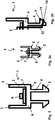
- Fig. 1 is shown in a schematic cross-sectional view of a fixing profile 1.
- the fixing profile 1 has a base 6 with a first side 7 and a second side 8.
- the first side 7 and the second side 8 of the base 6 of the fixing profile 1 are opposite each other.
- the first side 7 and the second side 8 of the base 6 of the fixing profile 1 are formed parallel to each other.
- an electric light-generating element 9 is arranged on the first side 7 of the base 6 of the fixing profile 1.
- the electric light-generating element 9 may be a light-emitting diode, wherein a light-emitting diode band 13 is preferred.
- a holding portion 2 is formed on the first side 7 of the base 6 of the fixing profile 1.
- the holding section 2 has two legs 3 projecting approximately perpendicularly from the first side 7.
- the legs 3 are arranged approximately parallel to each other and have approximately the same length.
- the holding section 2 is intended to define a light emitting body 14, not shown here.
- the fixing section 4 On the second side 8 of the base 6 of the fixing profile 1, a fixing section 4 is formed.
- the fixing section 4 has a fixing element 5, which in the present case is designed in the form of a latching foot.
- fixing profile 1 according to Fig. 1 are two fixing elements 5 formed as locking feet.
- the fixing section 4 on the base 6 of the fixing profile 1 serves to fasten the fixing profile 1.
- Fig. 2a is shown in a schematic cross-sectional view of a fixing profile 1 in a first embodiment.
- the reference numerals in Fig. 2a match those out Fig. 1 , Shown is in Fig. 2a schematically, that an electrical contact and electrically conductive connections are provided to supply the electric light-generating element 9 with electricity.
- Fig. 2b is in a detail enlargement of the fixing profile 1 from Fig. 2a shown.
- the reference numerals in Fig. 2b match those out Fig. 2a and from Fig. 1
- Fig. 2b is shown in detail that an electrically conductive connection 12 is formed, which is from a point 11, on which an electrical contact 10 is formed on the fixing portion 4, to the electric light-generating element 9 is present.
- the electrical contact 10 is arranged on the fixing element 5 in the form of a latching foot of the fixing section 4. It is thus possible to feed electrical energy to the electrical contact 10 and to direct this to the electric light-generating element 9, to stimulate this to shine.
- Fig. 3a is shown in a schematic cross-sectional view of a fixing profile 1 in a second embodiment.
- the reference numerals in Fig. 3a correspond to those of the preceding figures. Shown is in Fig. 3a schematically, that an electrical contact and electrically conductive connections are provided to supply the electric light-generating element 9 with electricity.
- Fig. 3b is an enlarged detail of the fixing profile 1 from Fig. 3a shown.
- the reference numerals in Fig. 3b correspond to those of the preceding figures.
- an electrically conductive connection 12 is formed. This is in connection with an electrical contact 10, which is disposed at a position 11 of the fixing portion 4. It is thus possible to supply electrical energy to the electrical contact 10 and to feed it with the aid of the electrically conductive connection 12 to the electric light-generating element 9 and to stimulate it to shine.
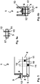
- Fig. 4 is a schematic partially sectioned perspective view of a fixing profile 1 is shown.
- the reference numerals in Fig. 4 correspond to those of the preceding figures.
- the light-emitting diode band 13 which is fixed to the base 6 of the fixing profile 1, is shown.
- the light-emitting diode strip 13 is fixed to the base 6 of the fixing profile 1 by means of an adhesive 16, for example an adhesive.
- the LED strip 13 is over the entire length L of the fixing profile 1, which in the Fig. 4 is only schematically indicated formed.
- Fig. 5 is a schematic partially sectioned side view of a fixing profile 1 is shown.
- the reference numerals in Fig. 5 correspond to those of the preceding figures.
- the electrical contact 10 may be formed at different locations 11 of the Festlegeabêts.
- the points 11 on which the electrical contact 10 is formed for example, in the region of the fixing element, so the locking foot, the fixing portion 4 or at another position of the fixing portion 4 may be formed.
- the electrical contact 10 is in contact with the electrically conductive connection 12 shown in dashed lines, so that a power line from the electrical contact 10 to the electrically conductive connection 12 and from there to the electric light-generating element 9, which is a light-emitting diode on a light-emitting diode band 13 at the Base 6 of the fixing profile 1 is fixed, can take place. In this way, the electric light-generating element 9 is energized when power supply to shine.
- Fig. 6a a schematic cross-sectional view of a Mixierelements 17 is shown.
- the reference numerals in Fig. 6a correspond to those of the preceding figures.
- the Kontierelement 17 has two opposite sides, wherein on one side at a location 11, an electrical contact 10 is formed, which is in contact with an electrically conductive connection 12. On this side of the contact element 17, a fixing element 5 is formed.
- Fig. 6b is a schematic cross-sectional view of a fixing profile 1 shown in a third embodiment.
- the reference numerals in Fig. 6b correspond to those of the preceding figures.
- This is the in Fig. 6a shown Kontakierelement 17 so connected to the base 6 of the fixing profile 1, that the electrically conductive connection 12, the light emitting diode band 13, which is fixed to the base 6, contacted so as to generate electrical energy from the electrical contact 10 at the point 11 of the fixing section 5 To transport light emitting diode band 13 and the electric light generating element 9 in the form of a light emitting diode.
- the fixing profile 1 With the fixing element 5 on the fixing section 4, the fixing profile 1 can be attached.
- Fig. 7 is shown in a schematic cross-sectional view of a fixing profile 1 with a fixed Lichtabstrahl stresses 14 in a first embodiment.
- the reference numerals in Fig. 7 correspond to those of the preceding figures.
- the fixing profile 1 holds at its holding portion 2 by means of two legs 3 a light emitting body 14 by clamping.
- the light emitting body 14 is fixed at a portion 15 of the legs 3 of the holding portion 2 of the fixing profile 1 by clamping.
- light which generates the electric light generating element 9 is irradiated into the light emitting body 14.
- the incident light is distributed in the light emitting body 14 and is discharged from the light emitting body 14 to the outside.
- Fig. 8 is shown in a schematic cross-sectional view of a fixing profile 1 with a fixed Lichtabstrahl Sciences 14 in a second embodiment.
- the reference numerals in Fig. 8 correspond to those of the preceding figures.
- the fixing profile 1 holds at its holding portion 2 by means of two legs 3 a light emitting body 14 by clamping.
- a reflector 19 is arranged on the legs 3 of the holding portion 2 of the fixing profile 1.
- the reflector 19 causes light exiting the light emitting body 14 to be reflected away from the fixing profile 1, thereby enabling directional light emission.
- a reflector 19 is provided on each leg 3 of the holding portion 2 of the fixing profile 1.
Landscapes
- Engineering & Computer Science (AREA)
- General Engineering & Computer Science (AREA)
- Led Device Packages (AREA)
- Non-Portable Lighting Devices Or Systems Thereof (AREA)
Abstract
Die Erfindung betrifft ein Festlegeprofil (1) für die Festlegung eines Lichtabstrahlkörpers (14), das eine Basis (6) aufweist, an der wenigstens ein elektrisches lichterzeugendes Element (9) angeordnet ist, und an der an einer ersten Seite (7) ein Halteabschnitt (2) und an einer zweiten Seite (8), die der ersten Seite (7) gegenüberliegt, ein Festlegeabschnitt (4) angeordnet ist, wobei der Halteabschnitt (2), der zwei etwa parallele von der Basis (6) etwa senkrecht wegstehende Schenkel (3) aufweist, zur Aufnahme eines Abschnitts (15) Lichtabstrahlkörpers (14) vorgesehen ist, und der Festlegeabschnitt (4) ein Festlegeelement (5) aufweist, da sich dadurch auszeichnet, dass an zumindest einer Stelle (11) des Festlegeabschnitts (4) des Festlegprofils (1) eine elektrische Kontaktierung (10) ausgebildet ist, die eine elektrisch leitende Verbindung (12) zum elektrischen lichterzeugenden Element (9) herstellt.
Description
- Die Erfindung betrifft ein Festlegeprofil zur Festlegung eines Lichtabstrahlkörpers.
- Lichtabstrahlkörper, wie beispielsweise sog. Lichtleiterplatten finden Einsatz bei Flächenleuchten. Bei solchen Flächenleuchten ist der Lichtabstrahlkörper allseitig von einer Rahmenanordnung umgeben, die diesen hält. Dadurch ist der Einsatz von solchen Flächenleuchten begrenzt. Auch ist die Kontaktierung der lichterzeugenden Elemente aufwendig, um diese mit Strom zu versorgen.
- Aufgabe der vorliegenden Erfindung ist es daher, ein Festlegeprofil zur Festlegung eines Lichtabstrahlkörpers zur Verfügung zu stellen, welches im Vergleich zu den bekannten Rahmenanordnungen aus dem Stand der Technik weiterentwickelt und verbessert ist.
- Die Lösung der geschilderten Aufgabe gelingt mit den Merkmalen des Anspruchs 1.
- Überraschenderweise wurde gefunden, dass ein Festlegeprofil für die Festlegung eines Lichtabstrahlkörpers, das eine Basis aufweist, an der wenigstens ein elektrisches lichterzeugendes Element angeordnet ist, und an der an einer ersten Seite ein Halteabschnitt und an einer zweiten Seite, die der ersten Seite gegenüberliegt, ein Festlegeabschnitt angeordnet ist, wobei der Halteabschnitt, der zwei etwa parallele von der Basis etwa senkrecht wegstehende Schenkel aufweist, zur Aufnahme eines Abschnitts des Lichtabstrahlkörpers vorgesehen ist, und der Festlegeabschnitt ein Festlegeelement aufweist, die gestellte Aufgabe vollumfänglich erfüllt, wenn vorgesehen ist, dass an zumindest einer Stelle des Festlegeabschnitts des Festlegeprofils eine elektrische Kontaktierung ausgebildet ist, die eine elektrisch leitende Verbindung zum elektrischen lichterzeugenden Element herstellt.
- Ein solches erfindungsgemäßes Festlegeprofil überwindet die Nachteile des Standes der Technik und löst die gestellte Aufgabe.
- Das erfindungsgemäße Festlegeprofil ist dabei derartig ausgestaltet, dass eine Basis vorgesehen ist, an der ein elektrisches lichterzeugendes Element angeordnet ist. Das elektrische lichterzeugende Element ist insbesondere eine Leuchtdiode, wobei ein Leuchtdiodenband, auf dem eine Vielzahl von Leuchtdioden angeordnet sind, bevorzug ist.
- In einer sehr vorteilhaften Ausgestaltung der vorliegenden Erfindung kann vorgesehen sein, dass eine Vielzahl von Leuchtdioden und / oder das Leuchtdiodenband entlang der gesamten Länge des Festlegeprofils angeordnet ist.
Hierdurch wird erreicht, dass entlang der gesamten Länge des Festlegeprofils Licht aus der Vielzahl von Leuchtdioden und / oder den Leuchtdioden des Leuchtdiodenbandes zur Verfügung steht, das in den vom Festlegeprofil aufnehmbaren Lichtabstrahlkörper einstrahlbar ist. - Es hat sich im Rahmen der vorliegenden Erfindung bewährt, wenn vorgesehen ist, dass das Leuchtdiodenband mit einem Haftmittel an der Basis des Festlegeprofils festgelegt ist. Bei einem solchen Haftmittel kann es sich beispielsweise um einen Klebstoff oder um ein Material handeln, welches adhäsiv zwischen dem Leuchtdiodenband und der Basis des Festlegeprofils wirkt.
Es ist dadurch ganz besonders einfach, das Leuchtdiodenband an der Basis des Festlegeprofils festzulegen, was den Arbeitsaufwand für die Herstellung eines solchen Festlegeprofils erleichtert und die Kosten zu dessen Herstellung senkt. - Die Basis des Festlegeprofils weist eine erste Seite auf und eine zweite Seite, die der ersten Seite gegenüberliegt.
In einer bevorzugten Ausgestaltung des erfindungsgemäßen Festlegeprofils sind die erste Seite und die zweite Seite etwa parallel zueinander angeordnet. - An der ersten Seite der Basis des Festlegeprofils ist ein Halteabschnitt angeordnet. Der Halteabschnitt an der Basis des Festlegeprofils weist zwei etwa parallele von der Basis etwa senkrecht wegstehende Schenkel auf. Durch das Vorsehen dieser zwei Schenkel kann der Halteabschnitt einen Abschnitt des Lichtabstrahlkörpers aufnehmen.
- Die Aufnahme eines Abschnitts des Lichtabstrahlkörpers vom Halteabschnitt an der Basis des Festlegeprofils kann dabei beispielsweise klemmend erfolgen, indem im Verbindungszustand des Halteabschnitts mit einem Abschnitt des Lichtabstrahlkörpers eine kraftschlüssige Verbindung durch Anlage der Schenkel auf die Oberfläche des Abschnitts des Lichtabstrahlkörpers hergestellt ist.
- In einer anderen Ausführungsform der vorliegenden Erfindung kann vorgesehen sein, dass der Abschnitt des Lichtabstrahlkörpers vom Halteabschnitt beispielsweise unter Zuhilfenahme eines Klebemittels aufgenommen ist.
- In einer anderen Ausführungsart der Erfindung kann vorgesehen sein, dass eine Schweißung zur Festlegung des Abschnitts des Lichtabstrahlkörpers am Halteabschnitt erfolgt.
- Es ist auch möglich, dass am Abschnitt des Lichtabstrahlkörpers Haltestrukturen ausgebildet sind, die mit entsprechenden komplementären Haltestrukturen an den Schenkeln des Halteabschnitts kraftschlüssig zusammenwirken und so der Lichtabstrahlkörper vom Halteabschnitt festgelegt ist.
- In einer bevorzugten Ausführungsform der vorliegenden Erfindung kann vorgesehen sein, dass an den Schenkeln des Halteabschnitts des Festlegeprofils ein Reflektor angeordnet ist. Ein solcher Reflektor kann bewirken, dass Licht, das aus dem Lichtabstrahlkörper austritt vom Festlegeprofil weg beispielsweise in den zu beleuchtenden Raum reflektiert wird. In einer ganz besonders bevorzugten Ausführungsform der Erfindung kann an jedem Schenkel des Halteabschnitts des Festlegeprofils ein Reflektor vorgesehen sein und so eine besonders intensive Reflexion des Lichts stattfinden.
- Das aus dem Lichtabstrahlkörper ausgekoppelte Licht kann durch die Form des Reflektors gerichtet werden. Dies kann durch die Form des Abstrahlkörpers weiter unterstützt werden.
- In einer bevorzugten Ausführungsform der Erfindung kann die Festlegung des Lichtabstrahlkörpers am Halteabschnitt derartig ausgebildet sein, dass das Festlegeprofil das Gewicht des Lichtabstrahlkörpers aufnehmen und tragen kann.
- An der zweiten Seite der Basis des Festlegeprofils ist ein Festlegeabschnitt angeordnet. Der Festlegeabschnitt weist ein Festlegeelement auf, um das Festlegeprofil befestigen zu können.
- Die Befestigung des Festlegeprofils am Festlegeabschnitt kann an einem hier nicht näher beschriebenen Aufnahmemittel erfolgen, wobei im befestigten Zustand des Festlegeprofils am Aufnahmemittel beispielsweise das Festlegeelement am Festlegeabschnitt mit einem komplementär ausgeformten Abschnitt des Aufnahmemittels kraftschlüssig zusammenwirkt.
- Es hat sich im Rahmen der vorliegenden Erfindung als vorteilhaft herausgestellt, wenn vorgesehen ist, dass das Festlegeelement als Fuß, insbesondere als Rastfuß ausgebildet ist. Es ist mithilfe eines Fußes, insbesondere eines Rastfußes, besonders einfach möglich, das Festlegeprofil zu befestigen.
- Ein wesentlicher Aspekt der vorliegenden Erfindung ist der, dass an zumindest einer Stelle des Festlegeabschnitts des Festlegeprofils eine elektrische Kontaktierung ausgebildet ist, die eine elektrisch leitende Verbindung zum elektrischen lichterzeugenden Element herstellt.
Durch diese Maßnahme gelingt es, bei der Befestigung des Festlegeprofils in einfacher Weise einen elektrischen Anschluss an das elektrische lichterzeugende Element herzustellen. - Hierzu ist eine elektrische Kontaktierung an zumindest einer Stelle des Festlegeabschnitts des erfindungsgemäßen Festlegeprofils ausgebildet.
- Die elektrische Kontaktierung kann als Kontaktfläche, insbesondere als federnde Kontaktfläche, als Stift, insbesondere als federnd gelagerter Stift oder als Federstift, als Nadel oder als Schraube oder dergleichen ausgebildet sein.
Durch die Ausbildung der elektrischen Kontaktierung gemäß vorstehender Beschreibung kann eine besonders einfache, sichere und kostengünstige Realisierung der Stromzufuhr zum elektrischen lichterzeugenden Element realisiert werden. Es kann auf diese Weise eine elektrische Versorgung des elektrischen lichterzeugenden Elements an der Basis des Festlegeprofils gemäß vorliegender Erfindung ohne großen Aufwand hergestellt werden. - Mit besonderem Vorteil kann bei dem erfindungsgemäßen Festlegeprofil vorgesehen sein, dass Leiterbahnen zur Versorgung des elektrischen lichterzeugenden Elements ausgebildet sind, wobei diese Leiterbahnen in Form von Litzen oder aufgedruckten Leiterbahnen oder aufgedampften Leiterbahnen oder Kupferflachleitern oder Stromschienen Kombinationen der Vorgenannten ausgebildet sind.
- Diese Leiterbahnen können zwischen dem elektrischen lichterzeugenden Element und der elektrischen Kontaktierung ausgebildet sein, so dass elektrische Energie von der elektrischen Kontaktierung zu dem elektrischen lichterzeugenden Element transportierbar ist.
- Das Festlegeprofil der vorliegenden Erfindung kann ein- oder mehrstückig ausgebildet sein.
- Bei einer einstückigen Ausbildung des Festlegeprofils kann dieses in einfacher Weise beispielsweise in einem Extrusionsprozess hergestellt und kostengünstig bereitgestellt werden.
- Ist das erfindungsgemäße Festlegeprofil mehrstückig ausgebildet, so kann beispielsweise ein Kontaktierelement vorgesehen sein, das es ermöglicht, je nach der Zusammenbausituation eine besonders einfache Kontaktiertechnik zur Stromversorgung des elektrischen lichterzeugenden Elements zur Verfügung zu stellen.
- Durch diese Maßnahme können insbesondere bei der Befestigung des erfindungsgemäßen Festlegeprofils neben der einfachen elektrischen Kontaktierung weitere Freiheitsgrade im Hinblick auf unterschiedliche Befestigungstechniken generiert werden.
- Es kann sich im Rahmen der vorliegenden Erfindung als ganz besonders günstig herausstellen, wenn vorgesehen ist, dass das erfindungsgemäße Festlegeprofil in einem Extrusionsverfahren, bevorzugt in einem Coextrusionsverfahren unter Anordnung des Leuchtdiodenbands am Festlegeprofil, hergestellt ist.
- Durch diese Maßnahme kann in einem einfachen Fertigungsprozess ein Festlegeprofil in unbegrenzter Länge kostengünstig hergestellt werden, das dann je nach den Notwendigkeiten auf die erforderlichen Längen abschneidbar ist. Durch die Anordnung des Leuchtdiodenbands am Festlegeprofil kann damit dann bereits das einsatzbereite Festlegeprofil zur Verfügung gestellt werden.
- Das Festlegeprofil kann auch in einem anderen Formgebungsverfahren, zum Beispiel in einem Spritzgussverfahren oder einem Thermoformverfahren oder einem Blasverfahren oder einer Kombination der vorgenannten Verfahren hergestellt sein.
- Alternativ ist es auch möglich, dass das Festlegeprofil unter Verwendung eines generativen Fertigungsverfahrens, insbesondere einstückig, beispielsweise durch ein 3-D-Druckverfahren, hergestellt werden kann.
- Hierzu kann mit Vorteil ein datenverarbeitungsmaschinenlesbares dreidimensionales Modell für die Herstellung genutzt werden.
- Die Erfindung umfasst auch ein Verfahren zur Erzeugung eines datenverarbeitungsmaschinenlesbaren dreidimensionalen Modells zur Verwendung in einem Herstellungsverfahren für ein Festlegeprofil.
Hierbei umfasst das Verfahren insbesondere auch die Eingabe von Daten, die ein Festlegeprofil darstellen, in eine Datenverarbeitungsmaschine und die Nutzung der Daten, um ein Festlegeprofil als dreidimensionales Modell darzustellen, wobei das dreidimensionale Modell geeignet ist zur Nutzung bei der Herstellung eines Festlegeprofils.
Ebenfalls umfasst ist bei dem Verfahren eine Technik, bei der die eingegebenen Daten eines oder mehrerer 3D-Scanner, die entweder auf Berührung oder berührungslos funktionieren, wobei bei letzteren Energie auf ein Festlegeprofil abgegeben wird und die reflektierte Energie empfangen wird, und wobei ein virtuelles dreidimensionales Modell eines Festlegeprofils unter Verwendung einer computerunterstützten Design-Software erzeugt wird. - Als ganz besonders günstig kann es sich bei der vorliegenden Erfindung ergeben, wenn vorgesehen ist, dass das erfindungsgemäße Festlegeprofil ein Polymermaterial enthält oder aus einem solchen besteht, wobei das Polymermaterial ein Polyolefin, wie beispielsweise ein Polyethylen oder ein Polypropylen oder ein Polybutylen, oder ein Polyamid oder ein Polystyrol oder ein ABS (Acrylnitril-Butadien-Styrol) oder ein Polyester oder ein Polycarbonat oder ein PVC (Polyvinylchlorid) oder ein PEEK (Polyetheretherketon) oder ein PEI (Polyetherimid) oder ein SAN (Styrol-Acrylnitril-Copolymer) oder ein POM (Polyoxymethylen) oder ein ASA (Acrylnitril-Styrol-Acrylester-Copolymer) oder ein Blend oder eine Mischung oder ein Copolymeres der Vorgenannten ist.
Durch die Verwendung eines Polymermaterials, insbesondere eines der vorgenannten Polymermaterialien, kann ein Festlegeprofil gemäß vorliegender Erfindung in kostengünstiger Weise bereitgestellt werden. - Die aufgeführten Polymermaterialien sind langlebig, inert, einfach formbar, temperaturstabil und leicht verfügbar.
- Die Polymermaterialien können mit einfachen Techniken eingefärbt werden, an ihrer Oberfläche vielfältig gestaltet und insbesondere dort auch dekoriert werden. Solche Festlegeprofile sind damit auch gestalterischen Maßnahmen einfach zugänglich.
- Das Festlegeprofil der vorliegenden Erfindung ist dafür vorgesehen, dass vom Halteabschnitt ein Abschnitt eines Lichtabstrahlkörpers aufgenommen ist.
- Der Abschnitt eines Lichtabstrahlkörpers ist bevorzugt ein Randabschnitt des Lichtabstrahlkörpers. Der Randabschnitt kann beispielsweise eine Breite von 5 mm bis 25 mm, bevorzugt von 10 mm bis 15 mm aufweisen.
- Der Lichtabstrahlkörper selber kann in bevorzugter Weise als Streuscheibe ausgebildet sein, die eine quadratische oder rechteckige Form aufweist. Auch andere Formen sind möglich, insbesondere solche, bei denen gekrümmte Abschnitte vorliegen.
- Zumindest ein Abschnitt einer Seite des Lichtabstrahlkörpers ist gemäß vorliegender Erfindung vom Halteabschnitt des Festlegeprofils aufgenommen. Bei entsprechender elektrischer Kontaktierung und Stromversorgung des elektrischen lichterzeugenden Elements kann dabei Licht in den Lichtabstrahlkörper eingestrahlt werden, der dieses Licht dann je nach der Ausbildung des Lichtabstrahlkörpers an die Umgebung abgibt.
- In einer günstigen Ausgestaltung der vorliegenden Erfindung kann vorgesehen sein, dass das elektrische lichterzeugende Element am Lichtabstrahlkörper anliegt und so eine besonders effektive Einkopplung von Licht aus dem elektrischen lichterzeugenden Element in den Lichtabstrahlkörper stattfindet.
- Das elektrische lichterzeugende Element kann vorteilhaft auch zumindest abschnittsweise mit Hilfe eines Polymermaterials an dem Lichtabstrahlkörper angebunden sein, um auf diese Weise effektiv Licht in diesen einzukoppeln.
Hierzu kann insbesondere ein Silikonkautschuk, ein Thermoplastisches Polyurethan (TPU) oder ein Thermoplastisches Elastomer auf Styrolbasis (TPES, SEBS), das auch MAHmodifiziert (Maleinsäureanhydrid-modifiziert) sein kann, eingesetzt werden. - Auf diese Weise kann eine transparente Verbindungsschicht zwischen dem elektrischen lichterzeugenden Element und dem Lichtabstrahlkörper geschaffen werden.
- In einer sehr vorteilhaften Fortbildung der vorliegenden Erfindung kann vorgesehen sein, dass zwischen dem elektrischen lichterzeugenden Element und dem Lichtabstrahlkörper eine farbige Folie und / oder eine farbige Schicht aus Polymermaterial und / oder ein Farbfilter und / oder farbige Lackschicht und / oder eine farbige Kleberschicht und / oder eine Lumineszenzkonverterschicht angeordnet ist.
Auf diese Weise kann beispielsweise weißes Licht von dem elektrischen lichterzeugenden Element ausgesendet werden, welches dann in farbiges Licht umgewandelt wird und vom Lichtabstrahlkörper in den Raum ausgesendet wird. - Als ganz besonders vorteilhaft kann es sich bei der vorliegenden Erfindung ergeben, wenn vorgesehen ist, dass das erfindungsgemäße Festlegeprofil eine Metallfolie oder ein Metallband oder eine Metallbeschichtung, die beispielsweise in einem Abscheideverfahren aufgebracht ist, aufweist.
- Durch diese Maßnahme kann die mechanische Stabilität des Festlegeprofils erhöht werden, so dass dieses unter Einwirkung einer Kraft nicht oder nur wenig zur Durchbiegung neigt. Auch die Längenausdehnung des Festlegeprofils bei Temperaturänderungen kann so reduziert werden.
Schließlich kann so auch ein gegebenenfalls stattfindender unerwünschter Lichtdurchtritt durch das Polymermaterial des Festlegeprofils vermindert oder unterbunden werden.
Eine Metallfolie oder ein Metallband an der Außenseite des Festlegeprofils kann im Sichtbereich des Festlegeprofils vorteilhaft als Dekorationselement genutzt werden. - Die Metallfolie oder das Metallband kann in der Matrix des Polymermaterials des Festlegeprofils angeordnet sein, oder an einem Oberflächenabschnitt des Festlegeprofils.
- Es kann auch vorgesehen sein, dass das Festlegeprofil Verstärkungselemente aufweist, die Metallfasern und / oder Metallwhisker und / oder Keramikfasern und / oder Keramikwhisker und / oder Glasfasern und / oder Polymerfasern, wobei es sich um Lang- und / oder Kurzfasern handeln kann, enthalten.
Auch bandförmige Verstärkungselemente sind möglich. - Das Festlegeprofil der vorliegenden Erfindung kann auch zu einer Rahmenkonstruktion zusammengefügt werden und einen Lichtabstrahlkörper aufnehmen.
Eine solche Rahmenkonstruktion kann beispielsweise aus vier gleich langen Stücken des Festlegeprofils bestehen, die an ihren Enden verbunden sind, so dass eine quadratische Rahmenkonstruktion vorliegt. In einer anderen Ausführungsart kann auch vorgesehen sein, dass zwei Stücke mit einer ersten Länge und zwei Stück mit einer zweiten Länge zu einer rechteckigen Rahmenkonstruktion verbunden sind.
Es lassen sich so auch Rahmenkonstruktionen herstellen, die dreieckig, fünfeckig oder mehreckig ausgebildet sind. Auch gekrümmte Stücke des Festlegeprofils lassen sich verarbeiten, so dass Rahmenkonstruktionen gebildet werden können, die beispielsweise Kreisabschnitte oder Kurvenabschnitte aufweisen. - Weitere wichtige Merkmale und Vorteile der Erfindung ergeben sich aus den Unteransprüchen, aus den Figuren und aus der zugehörigen Figurenbeschreibung.
- Es versteht sich, dass die vorstehend genannten und die nachstehend noch zu erläuternden Merkmale nicht nur in der jeweils angegebenen Kombination, sondern auch in anderen Kombinationen oder in Alleinstellung verwendbar sind, ohne den Rahmen der vorliegenden Erfindung zu verlassen.
- Bevorzugte Ausführungsbeispiele der Erfindung sind in den Fig. dargestellt und werden in der nachfolgenden Beschreibung näher erläutert.
- Hierzu zeigen:
- Fig.1
- eine schematische Querschnittsansicht eines Festlegeprofils;
- Fig. 2a
- eine schematische Querschnittsansicht eines Festlegeprofils in einer ersten Ausführungsform;
- Fig. 2b
- eine Detailvergrößerung des Festlegeprofils aus
Fig. 2a ; - Fig. 3a
- eine schematische Querschnittsansicht eines Festlegeprofils in einer zweiten Ausführungsform;
- Fig. 3b
- eine Detailvergrößerung des Festlegeprofils aus
Fig. 3a ; - Fig. 4
- eine schematische teilweise geschnittene perspektivische Ansicht eines Festlegeprofils;
- Fig. 5
- eine schematische teilweise geschnittene seitliche Ansicht eines Festlegeprofils;
- Fig. 6a
- eine schematische Querschnittsansicht eines Kontaktierelements;
- Fig. 6b
- eine schematische Querschnittsansicht eines Festlegeprofils in einer dritten Ausführungsform;
- Fig. 7
- eine schematische Querschnittsansicht eines Festlegeprofils mit einem festgelegten Lichtabstrahlkörper in einer ersten Ausführung;
- Fig. 8
- eine schematische Querschnittsansicht eines Festlegeprofils mit einem festgelegten Lichtabstrahlkörper in einer zweiten Ausführung.
- In
Fig. 1 ist in einer schematischen Querschnittsansicht ein Festlegeprofil 1 gezeigt. Das Festlegeprofil 1 weist eine Basis 6 auf mit einer ersten Seite 7 und einer zweiten Seite 8. Die erste Seite 7 und die zweite Seite 8 der Basis 6 des Festlegeprofils 1 liegen sich gegenüber. In einer besonderen Ausführungsform des Festlegeprofils 1, die hier gezeigt ist, sind die erste Seite 7 und die zweite Seite 8 der Basis 6 des Festlegeprofils 1 parallel zueinander ausgebildet.
An der ersten Seite 7 der Basis 6 des Festlegeprofils 1 ist ein elektrisches lichterzeugendes Element 9 angeordnet. Das elektrische lichterzeugende Element 9 kann eine Leuchtdiode sein, wobei ein Leuchtdiodenband 13 bevorzugt ist.
An der ersten Seite 7 der Basis 6 des Festlegeprofils 1 ist ein Halteabschnitt 2 ausgebildet. Der Halteabschnitt 2 weist zwei etwa senkrecht von der ersten Seite 7 wegstehende Schenkel 3 auf. Die Schenkel 3 sind zueinander etwa parallel angeordnet und weisen etwa die gleiche Länge auf. Der Halteabschnitt 2 ist dafür vorgesehen, einen hier nicht gezeigten Lichtabstrahlkörper 14 festzulegen. - An der zweiten Seite 8 der Basis 6 des Festlegeprofils 1 ist ein Festlegeabschnitt 4 ausgebildet. Der Festlegeabschnitt 4 weist ein Festlegeelement 5 auf, das vorliegend in Form eines Rastfußes ausgebildet ist. Beim Festlegeprofil 1 gemäß
Fig. 1 sind zwei Festlegeelemente 5 als Rastfüße ausgebildet.
Der Festlegeabschnitt 4 an der Basis 6 des Festlegeprofils 1 dient dazu, das Festlegeprofil 1 zu befestigen. - In
Fig. 2a ist in einer schematischen Querschnittsansicht ein Festlegeprofil 1 in einer ersten Ausführungsform gezeigt.
Die Bezugszeichen inFig. 2a entsprechen denen ausFig. 1 .
Gezeigt ist inFig. 2a in schematischer Weise, dass eine elektrische Kontaktierung und stromleitende Verbindungen vorgesehen sind, um das elektrische lichterzeugende Element 9 mit Strom zu versorgen. - In
Fig. 2b ist in einer Detailvergrößerung das Festlegeprofil 1 ausFig. 2a dargestellt.
Die Bezugszeichen inFig. 2b entsprechen denen ausFig. 2a und ausFig. 1 .
InFig. 2b ist im Detail gezeigt, dass eine elektrisch leitende Verbindung 12 ausgebildet ist, die von einer Stelle 11, an der eine elektrische Kontaktierung 10 am Festlegeabschnitt 4 ausgebildet ist, zum elektrisch lichterzeugenden Element 9 vorliegt.
Die elektrische Kontaktierung 10 ist dabei am Festlegeelement 5 in Form eines Rastfußes des Festlegeabschnitts 4 angeordnet. Es ist damit möglich, elektrische Energie an der elektrischen Kontaktierung 10 einzuspeisen und diese zum elektrischen lichterzeugenden Element 9 zu leiten, um dieses zum Leuchten anzuregen. - In
Fig. 3a ist in einer schematischen Querschnittsansicht ein Festlegeprofil 1 in einer zweiten Ausführungsform dargestellt.
Die Bezugszeichen inFig. 3a entsprechen denen aus den vorangehenden Figuren. Gezeigt ist inFig. 3a in schematischer Weise, dass eine elektrische Kontaktierung und stromleitende Verbindungen vorgesehen sind, um das elektrische lichterzeugende Element 9 mit Strom zu versorgen. - In
Fig. 3b ist eine Detailvergrößerung des Festlegeprofils 1 ausFig. 3a gezeigt.
Die Bezugszeichen inFig. 3b entsprechen denen aus den vorangehenden Figuren.
Um das elektrische lichterzeugende Element 9 mit Strom zu versorgen, ist eine elektrisch leitende Verbindung 12 ausgebildet. Diese steht in Verbindung mit einer elektrischen Kontaktierung 10, die an einer Stelle 11 des Festlegeabschnitts 4 angeordnet ist. Es ist damit möglich, elektrische Energie an der elektrischen Kontaktierung 10 einzuspeisen und diese mithilfe der elektrisch leitenden Verbindung 12 dem elektrischen lichterzeugenden Element 9 zuzuleiten und dieses zum Leuchten anzuregen. - In
Fig. 4 ist eine schematische teilweise geschnittene perspektivische Ansicht eines Festlegeprofils 1 gezeigt.
Die Bezugszeichen inFig. 4 entsprechen denen aus den vorangehenden Figuren.
Bei dieser Ansicht des Festlegeprofils 1 ist das Leuchtdiodenband 13, das an der Basis 6 des Festlegeprofils 1 festgelegt ist, dargestellt.
Auf dem Leuchtdiodenband 13 sind eine Vielzahl von elektrischen lichterzeugenden Elementen 9, insbesondere Leuchtdioden angeordnet. Das Leuchtdiodenband 13 ist an der Basis 6 des Festlegeprofils 1 mithilfe eines Haftmittels 16, beispielsweise eines Klebstoffs, festgelegt.
Das Leuchtdiodenband 13 ist über die gesamte Länge L des Festlegeprofils 1, die in derFig. 4 lediglich schematisch angegeben ist, ausgebildet. - In
Fig. 5 ist eine schematische teilweise geschnittene seitliche Ansicht eines Festlegeprofils 1 gezeigt.
Die Bezugszeichen inFig. 5 entsprechen denen aus den vorangehenden Figuren.
In schematischer Weise ist inFig. 5 gezeigt, dass die elektrische Kontaktierung 10 an unterschiedlichen Stellen 11 des Festlegeabschnitts ausgebildet sein kann. Mit Bezug auf dieFiguren 2b und3b ist gezeigt, dass die Stellen 11, an denen die elektrische Kontaktierung 10 ausgebildet ist, beispielsweise im Bereich des Festlegeelements, also des Rastfußes, des Festlegeabschnitts 4 oder an einer anderen Stelle des Festlegeabschnitts 4 ausgebildet sein kann.
Die elektrische Kontaktierung 10 ist dabei mit der gestrichelt gezeigten elektrisch leitenden Verbindung 12 in Kontakt, sodass eine Stromleitung von der elektrischen Kontaktierung 10 zur elektrisch leitenden Verbindung 12 und von dort zum elektrischen lichterzeugenden Element 9, das als Leuchtdiode auf einem Leuchtdiodenband 13, das an der Basis 6 des Festlegeprofils 1 festgelegt ist, erfolgen kann. Auf diese Weise wird das elektrische lichterzeugende Element 9 bei Stromzuführung zum Leuchten angeregt. - In
Fig. 6a ist eine schematische Querschnittsansicht eines Kontaktierelements 17 gezeigt. Die Bezugszeichen inFig. 6a entsprechen denen aus den vorangehenden Figuren. - Das Kontierelement 17 weist zwei gegenüberliegende Seiten auf, wobei an der einen Seite an einer Stelle 11 eine elektrische Kontaktierung 10 ausgebildet ist, die mit einer elektrisch leitenden Verbindung 12 in Kontakt steht. An dieser Seite des Kontaktierelements 17 ist ein Festlegeelement 5 ausgebildet.
- In
Fig. 6b ist eine schematische Querschnittsansicht eines Festlegeprofils 1 in einer dritten Ausführungsform dargestellt.
Die Bezugszeichen inFig. 6b entsprechen denen aus den vorangehenden Figuren.
Hierzu ist das inFig. 6a gezeigte Kontakierelement 17 derartig mit der Basis 6 des Festlegeprofils 1 verbunden, dass die elektrisch leitende Verbindung 12 das Leuchtdiodenband 13, das an der Basis 6 festgelegt ist, kontaktiert, um so elektrische Energie von der elektrischen Kontaktierung 10 an der Stelle 11 des Festlegeabschnitts 5 zum Leuchtdiodenband 13 und zum elektrischen lichterzeugenden Element 9 in Form einer Leuchtdiode zu transportieren.
Mit dem Festlegeelement 5 am Festlegeabschnitt 4 kann das Festlegeprofil 1 befestigt werden. - In
Fig. 7 ist in einer schematischen Querschnittsansicht ein Festlegeprofil 1 mit einem festgelegten Lichtabstrahlkörper 14 in einer ersten Ausführung gezeigt.
Die Bezugszeichen inFig. 7 entsprechen denen aus den vorangehenden Figuren.
Das Festlegeprofil 1 hält an seinem Halteabschnitt 2 mithilfe von zwei Schenkeln 3 einen Lichtabstrahlkörper 14 klemmend fest.
Der Lichtabstrahlkörper 14 ist dabei an einem Abschnitt 15 von den Schenkeln 3 des Halteabschnitts 2 des Festlegeprofils 1 klemmend fixiert.
Durch die Stirnfläche 18 des Lichtabstrahlkörpers 14 wird Licht, das das elektrische lichterzeugende Element 9 erzeugt, in den Lichtabstrahlkörper 14 eingestrahlt. Das eingestrahlte Licht verteilt sich im Lichtabstrahlkörper 14 und wird aus dem Lichtabstrahlkörper 14 nach außen abgegeben. - In
Fig. 8 ist in einer schematischen Querschnittsansicht ein Festlegeprofil 1 mit einem festgelegten Lichtabstrahlkörper 14 in einer zweiten Ausführung gezeigt.
Die Bezugszeichen inFig. 8 entsprechen denen aus den vorangehenden Figuren.
Das Festlegeprofil 1 hält an seinem Halteabschnitt 2 mithilfe von zwei Schenkeln 3 einen Lichtabstrahlkörper 14 klemmend fest. - An den Schenkeln 3 des Halteabschnitts 2 des Festlegeprofils 1 ist ein Reflektor 19 angeordnet. Der Reflektor 19 bewirkt, dass Licht, das aus dem Lichtabstrahlkörper 14 austritt, vom Festlegeprofil 1 weg reflektiert wird, wodurch eine gerichtete Lichtabstrahlung ermöglicht wird. In der vorliegenden Ausführungsform ist an jedem Schenkel 3 des Halteabschnitts 2 des Festlegeprofils 1 ein Reflektor 19 vorgesehen.
-
- 1
- Festlegeprofil
- 2
- Halteabschnitt
- 3
- Schenkel
- 4
- Festlegeabschnitt
- 5
- Festlegeelement
- 6
- Basis
- 7
- erste Seite
- 8
- zweite Seite
- 9
- elektrisches lichterzeugendes Element
- 10
- elektrische Kontaktierung
- 11
- Stelle
- 12
- elektrisch leitende Verbindung
- 13
- Leuchtdiodenband
- 14
- Lichtabstrahlkörper
- 15
- Abschnitt
- 16
- Haftmittel
- 17
- Kontaktierelement
- 18
- Stirnfläche
- 19
- Reflektor
- L
- Länge
Claims (10)
- Festlegeprofil (1) für die Festlegung eines Lichtabstrahlkörpers (14), das eine Basis (6) aufweist, an der wenigstens ein elektrisches lichterzeugendes Element (9) angeordnet ist, und an der an einer ersten Seite (7) ein Halteabschnitt (2) und an einer zweiten Seite (8), die der ersten Seite (7) gegenüberliegt, ein Festlegeabschnitt (4) angeordnet ist, wobei der Halteabschnitt (2), der zwei etwa parallele von der Basis (6) etwa senkrecht wegstehende Schenkel (3) aufweist, zur Aufnahme eines Abschnitts (15) des Lichtabstrahlkörpers (14) vorgesehen ist, und der Festlegeabschnitt (4) ein Festlegeelement (5) aufweist, dadurch gekennzeichnet, dass an zumindest einer Stelle (11) des Festlegeabschnitts (4) des Festlegeprofils (1) eine elektrische Kontaktierung (10) ausgebildet ist, die eine elektrisch leitende Verbindung (12) zum elektrischen lichterzeugenden Element (9) herstellt.
- Festlegeprofil (1) nach Anspruch 1, dadurch gekennzeichnet, dass die elektrische Kontaktierung (10) als Kontaktfläche, insbesondere als federnde Kontaktfläche, als Stift, insbesondere als federnd gelagerter Stift oder als Federstift, als Nadel oder als Schraube ausgebildet ist.
- Festlegeprofil (1) nach einem der Ansprüche 1 oder 2, dadurch gekennzeichnet, dass das Festlegeelement (5) als Fuß, insbesondere als Rastfuß, ausgebildet ist.
- Festlegeprofil (1) nach einem der vorangehenden Ansprüche, dadurch gekennzeichnet, dass das elektrische lichterzeugende Element (9) insbesondere eine Leuchtdiode, bevorzugt ein Leuchtdiodenband (13) ist.
- Festlegeprofil (1) nach Anspruch 4, dadurch gekennzeichnet, dass eine Mehrzahl von elektrischen lichterzeugenden Elementen (9) und / oder das Leuchtdiodenband (13) entlang der gesamten Länge L des Festlegeprofils (1) angeordnet ist.
- Festlegeprofil (1) nach einem der Ansprüche 4 oder 5, dadurch gekennzeichnet, dass das Leuchtdiodenband (13) mit einem Haftmittel (16) an der Basis (6) des Festlegeprofils (1) festgelegt ist.
- Festlegeprofil (1) nach einem der vorangehenden Ansprüche, dadurch gekennzeichnet, dass dieses ein- oder mehrstückig ausgebildet ist.
- Festlegeprofil (1) nach einem der vorangehenden Ansprüche, dadurch gekennzeichnet, dass dieses in einem Extrusionsverfahren, bevorzugt in einem Coextrusionsverfahren unter Anordnung des Leuchtdiodenbands (13) am Festlegeprofil (1), hergestellt ist.
- Festlegeprofil (1) nach einem der vorangehenden Ansprüche, dadurch gekennzeichnet, dass dieses ein Polymermaterial enthält oder aus einem solchen besteht, wobei des Polymermaterial ein Polyolefin, wie beispielsweise ein Polyethylen oder ein Polypropylen oder ein Polybutylen, oder ein Polyamid oder ein Polystyrol oder ein ABS (Acrylnitril-Butadien-Styrol) oder ein Polyester oder ein Polycarbonat oder ein Polyvinylchlorid (PVC) oder ein PEEK (Polyetheretherketon) oder ein PEI (Polyetherimid) oder ein SAN (Styrol-Acrylnitril-Copolymer) oder ein POM (Polyoxymethylen) oder ein ASA (Acrylnitril-Styrol-Acrylaester-Copolymer)oder ein Blend oder eine Mischung oder ein Copolymeres der Vorgenannten ist.
- Festlegeprofil (1) nach einem der Ansprüche 1 bis 9, wobei vom Halteabschnitt (2) ein Abschnitt (15) eines Lichtabstrahlkörpers (14) aufgenommen ist.
Applications Claiming Priority (1)
| Application Number | Priority Date | Filing Date | Title |
|---|---|---|---|
| DE202016102425.0U DE202016102425U1 (de) | 2016-05-06 | 2016-05-06 | Festlegeprofil |
Publications (1)
| Publication Number | Publication Date |
|---|---|
| EP3242077A1 true EP3242077A1 (de) | 2017-11-08 |
Family
ID=58698945
Family Applications (1)
| Application Number | Title | Priority Date | Filing Date |
|---|---|---|---|
| EP17167898.0A Withdrawn EP3242077A1 (de) | 2016-05-06 | 2017-04-25 | Festlegeprofil |
Country Status (2)
| Country | Link |
|---|---|
| EP (1) | EP3242077A1 (de) |
| DE (1) | DE202016102425U1 (de) |
Cited By (1)
| Publication number | Priority date | Publication date | Assignee | Title |
|---|---|---|---|---|
| EP4459177A1 (de) * | 2023-05-03 | 2024-11-06 | Tridonic GmbH & Co. KG | Leuchtenkomponente und leuchte für notlicht- oder ausgangsschildanwendungen |
Families Citing this family (1)
| Publication number | Priority date | Publication date | Assignee | Title |
|---|---|---|---|---|
| IT201900005446A1 (it) * | 2019-04-09 | 2020-10-09 | Artemide Spa | Elemento luminoso a led per sistemi di illuminazione e sistema di illuminazione comprendente tale elemento luminoso |
Citations (5)
| Publication number | Priority date | Publication date | Assignee | Title |
|---|---|---|---|---|
| US20100328945A1 (en) * | 2009-06-30 | 2010-12-30 | Fu Zhun Precision Industry (Shen Zhen) Co., Ltd. | Led lamp |
| US20130208495A1 (en) * | 2011-08-08 | 2013-08-15 | Quarkstar Llc | Illumination Devices including Multiple Light Emitting Elements |
| US20150085521A1 (en) * | 2013-09-23 | 2015-03-26 | Glo Ab | Integrated back light unit |
| DE102014103974A1 (de) * | 2014-03-24 | 2015-09-24 | Alanod Gmbh & Co. Kg | Stromschiene zum Anschluss von Leuchtdioden |
| WO2016029291A1 (en) * | 2014-08-29 | 2016-03-03 | Certainteed Canada, Inc. | Strip light arrangement for t bar ceiling grid systems |
Family Cites Families (3)
| Publication number | Priority date | Publication date | Assignee | Title |
|---|---|---|---|---|
| DE2747272A1 (de) * | 1977-10-21 | 1979-04-26 | Licentia Gmbh | Halterung fuer elektronische bauelemente |
| WO2005088191A1 (ja) * | 2004-03-11 | 2005-09-22 | Moriyama Sangyo Kabushiki Kaisha | ソケット装置 |
| DE202012000083U1 (de) * | 2012-01-05 | 2012-02-06 | Oechsle Display Systeme Gmbh | LED Leuchteinheit mit einfach zu wechselndem Leuchtmittel |
-
2016
- 2016-05-06 DE DE202016102425.0U patent/DE202016102425U1/de not_active Expired - Lifetime
-
2017
- 2017-04-25 EP EP17167898.0A patent/EP3242077A1/de not_active Withdrawn
Patent Citations (5)
| Publication number | Priority date | Publication date | Assignee | Title |
|---|---|---|---|---|
| US20100328945A1 (en) * | 2009-06-30 | 2010-12-30 | Fu Zhun Precision Industry (Shen Zhen) Co., Ltd. | Led lamp |
| US20130208495A1 (en) * | 2011-08-08 | 2013-08-15 | Quarkstar Llc | Illumination Devices including Multiple Light Emitting Elements |
| US20150085521A1 (en) * | 2013-09-23 | 2015-03-26 | Glo Ab | Integrated back light unit |
| DE102014103974A1 (de) * | 2014-03-24 | 2015-09-24 | Alanod Gmbh & Co. Kg | Stromschiene zum Anschluss von Leuchtdioden |
| WO2016029291A1 (en) * | 2014-08-29 | 2016-03-03 | Certainteed Canada, Inc. | Strip light arrangement for t bar ceiling grid systems |
Cited By (2)
| Publication number | Priority date | Publication date | Assignee | Title |
|---|---|---|---|---|
| EP4459177A1 (de) * | 2023-05-03 | 2024-11-06 | Tridonic GmbH & Co. KG | Leuchtenkomponente und leuchte für notlicht- oder ausgangsschildanwendungen |
| WO2024227587A1 (en) * | 2023-05-03 | 2024-11-07 | Tridonic Gmbh & Co Kg | Luminaire component and luminaire for emergency light or exit sign applications |
Also Published As
| Publication number | Publication date |
|---|---|
| DE202016102425U1 (de) | 2017-08-09 |
Similar Documents
| Publication | Publication Date | Title |
|---|---|---|
| DE102008025398B4 (de) | Schutzumhüllung für ein LED-Band | |
| DE102011016417A1 (de) | Leuchtendes Formteil, insbesondere Dekorteil und/oder Verkleidungsteil für einen Fahrzeuginnenraum | |
| DE102016121047B4 (de) | Herstellungsverfahren für eine beleuchtungseinrichtung | |
| DE102010038251A1 (de) | OLED-Leuchtmittel für eine Leuchte | |
| DE202017100874U1 (de) | Beleuchtungsvorrichtung für ein Innenausstattungsteil | |
| DE102009005351A1 (de) | Lichtleiter für eine Lampe | |
| DE202018105499U1 (de) | Leuchtstreifen | |
| DE102006039705A1 (de) | Linsenvorsatz für einen Scheinwerfer | |
| DE202014104585U1 (de) | Lichtleitsystem mit einer Lichtröhre | |
| DE102015215254A1 (de) | Beleuchtetes Gurtschloss für eine Sicherheitsgurteinrichtung eines Kraftfahrzeuges | |
| EP3631290B1 (de) | Beleuchtungsvorrichtung zur beleuchtung des innenraums eines kraftfahrzeugs | |
| DE102013202224A1 (de) | Funktionale Überbrückung von Dekoröffnungen | |
| DE202016102425U1 (de) | Festlegeprofil | |
| EP1328140A2 (de) | Leiterbahn aus flexiblem Material, Baueinheit mit einer solchen flexiblen Leiterbahn und Verfahren zur Herstellung einer solchen Leiterbahn | |
| DE10231324A1 (de) | Innenleuchte für Fahrzeuge | |
| EP3792111A1 (de) | Leuchte | |
| DE102011002480A1 (de) | Leuchte mit flexibler OLED und Rahmen | |
| DE202016102427U1 (de) | Leuchte | |
| DE102022130883A1 (de) | Möbel mit einem Möbelgrundkörper und einer Lichtverteilerleiste | |
| DE102015222187A1 (de) | Wannenleuchte | |
| DE102019009210B4 (de) | Vollflächig durchleuchtbares Dekorteil | |
| DE2640717C3 (de) | Gleitkontaktanordnung, insbesondere für schienenlose elektrische Spielfahrzeuge | |
| DE102021120794A1 (de) | Beleuchtungsvorrichtung, Innenverkleidungsanordnung mit der Beleuchtungsvorrichtung und Verfahren zur Herstellung einer Verkleidungsanordnung | |
| DE102004003123A1 (de) | Haftverschlussteil mit Leuchtmittel und Verfahren zum Herstellen eines solchen Haftverschlussteils | |
| DE10032837B4 (de) | Lichtleiter und Lichtleitermodul |
Legal Events
| Date | Code | Title | Description |
|---|---|---|---|
| PUAI | Public reference made under article 153(3) epc to a published international application that has entered the european phase |
Free format text: ORIGINAL CODE: 0009012 |
|
| AK | Designated contracting states |
Kind code of ref document: A1 Designated state(s): AL AT BE BG CH CY CZ DE DK EE ES FI FR GB GR HR HU IE IS IT LI LT LU LV MC MK MT NL NO PL PT RO RS SE SI SK SM TR |
|
| AX | Request for extension of the european patent |
Extension state: BA ME |
|
| STAA | Information on the status of an ep patent application or granted ep patent |
Free format text: STATUS: THE APPLICATION IS DEEMED TO BE WITHDRAWN |
|
| 18D | Application deemed to be withdrawn |
Effective date: 20180509 |