EP3241479B1 - Connect/disconnect arrangement for revolving sprinklers of dishwashers - Google Patents
Connect/disconnect arrangement for revolving sprinklers of dishwashers Download PDFInfo
- Publication number
- EP3241479B1 EP3241479B1 EP16425037.5A EP16425037A EP3241479B1 EP 3241479 B1 EP3241479 B1 EP 3241479B1 EP 16425037 A EP16425037 A EP 16425037A EP 3241479 B1 EP3241479 B1 EP 3241479B1
- Authority
- EP
- European Patent Office
- Prior art keywords
- latches
- rotor
- hub
- pivot
- sprinkler
- Prior art date
- Legal status (The legal status is an assumption and is not a legal conclusion. Google has not performed a legal analysis and makes no representation as to the accuracy of the status listed.)
- Active
Links
Images


Classifications
-
- A—HUMAN NECESSITIES
- A47—FURNITURE; DOMESTIC ARTICLES OR APPLIANCES; COFFEE MILLS; SPICE MILLS; SUCTION CLEANERS IN GENERAL
- A47L—DOMESTIC WASHING OR CLEANING; SUCTION CLEANERS IN GENERAL
- A47L15/00—Washing or rinsing machines for crockery or tableware
- A47L15/14—Washing or rinsing machines for crockery or tableware with stationary crockery baskets and spraying devices within the cleaning chamber
- A47L15/18—Washing or rinsing machines for crockery or tableware with stationary crockery baskets and spraying devices within the cleaning chamber with movably-mounted spraying devices
- A47L15/22—Rotary spraying devices
- A47L15/23—Rotary spraying devices moved by means of the sprays
Definitions
- the present invention relates to professional dishwashers or similar machines, such as apparatuses for disinfection, and in particular to a dishwasher provided with a quick connect/disconnect system of the revolving sprinkler which makes it easily mountable and removable.
- a conventional revolving sprinkler essentially consists of an elongated tubular body that is centrally pivoted on a hollow pivot with a vertical axis, corresponding to the axis of rotation of the sprinkler, mounted at the outlet of a water supply duct.
- the rotatory motion about this axis is usually created by at least one propulsion nozzle at each end, the jet emitted by such a nozzle being substantially perpendicular to the axis of rotation, while washing nozzles are arranged along the sprinkler to emit jets substantially parallel to the axis of rotation.
- the sprinkler is mounted on the hollow pivot in a removable manner so that it can be removed when it is necessary to carry out the periodical cleaning or sanitizing of the sprinkler by removing dirt and deposits that can build up inside it.
- the sprinkler removal implies a downtime whose duration should be limited as much as possible, in order to maintain high productivity of the dishwasher.
- the conventional sprinkler connect/disconnect systems are not optimal in this respect, both in the time required for the connecting/disconnecting of the sprinkler and in the complexity of the systems that are quite expensive to manufacture, inconvenient to use and of low reliability.
- US 5211190 discloses a connect/disconnect system of a revolving sprinkler that corresponds to the preamble of claim 1, such a system requiring a snap-fit arrangement between a lower coupling stud and an upper coupling member in order to mount the sprinkler at the outlet of a water supply duct by means of a threaded connection between said upper coupling member and said outlet. Therefore the replacement of the sprinkler requires the unthreading of the upper coupling member from the outlet and the forced disengagement of the lower coupling stud from the upper coupling member.
- the object of the present invention is therefore to provide a quick connect/disconnect system of the revolving sprinkler that overcomes the above-described limitations of prior art systems.
- This object is achieved by means of a system in which the hollow pivot on which the sprinkler is pivoted has a terminal portion with a cylindrical shape surmounted by a frusto-conical end shape with the larger base adjacent to said cylindrical shape and of a diameter greater than it, the sprinkler being pivoted on said pivot by means of a hub which accommodates at least two latches radially sliding with respect to the longitudinal axis of the pivot in correspondence with its cylindrical shape and biased toward said longitudinal axis by corresponding resilient means, said hub also accomodating a rotor in contact with said sliding latches and shaped in such a way that its rotation in a given direction moves the latches away from the pivot axis up to a distance greater than the radius of said larger base of the frusto-conical shape, said rotor being provided with a gripping member external to the
- the main advantage of the connect/disconnect system of the sprinkler according to the present invention is that of being extremely quick and easy to use, even with one hand only, by the operator.
- a further advantage of this system stems from the fact that its simple and rugged design ensures greater reliability and a lower cost.
- a quick connect/disconnect system of a revolving sprinkler comprises a hollow pivot 1 mounted on a supply pipe (not shown) and provided with a terminal portion with a cylindrical shape 1a surmounted by a frusto-conical end shape 1b, whose larger base is adjacent to said cylindrical shape 1a and has a diameter larger than it so as to form an undercut.
- a connect/disconnect system for a sprinkler that is fed from below, but it is clear that what is said also applies to a sprinkler that is fed from above, i.e. with pivot 1 facing down.
- the sprinkler is pivoted on pivot 1 by means of a hub 2 which internally accommodates at least two latches 3 sliding radially with respect to the longitudinal axis of pivot 1 in correspondence with the cylindrical shape 1a.
- Said latches 3 are preferably arranged at equidistant positions along the perimeter of hub 2, and are biased towards the longitudinal axis of pivot 1 by corresponding springs 4 so as to engage the undercut formed in the terminal portion of pivot 1.
- Hub 2 also accommodates a rotor 5 which is rotatable with respect thereto and in contact with the upper faces of the sliding latches 3, in particular with projections 3a formed on said upper faces.
- Rotor 5 is shaped with cam profiles 5a in the parts in contact with said projections 3a in such a way that its rotation in a given direction (clockwise in the example shown) moves the sliding latches 3 away from the axis of pivot 1 up to a distance greater than the radius of the larger base of the frusto-conical shape 1b, so that latches 3 are disengaged from pivot 1 ( Fig.3 ).
- Rotor 5 is also made integral with a lever 6 external to hub 2, passing through a cover 7 of the hub, so as to allow an operator to rotate rotor 5 by acting on lever 6 with a rotation in the horizontal plane.
- the sprinkler connect/disconnect system achieves the desired results of low cost, strength and ease of removal and repositioning of the sprinkler since a limited rotation of lever 6 (of about 20° in the illustrated example) is sufficient to turn rotor 5 that pushes with the cam profiles 5a on projections 3a overcoming the resistance of springs 4 and moves the sliding latches 3 away from pivot 1 enough to disengage the sprinkler, which can thus be easily removed using only one hand.
- the movement of latches 3 is a smooth sliding linear motion since they are received in suitable guides formed in hub 2 and retained therein by cover 7, and that the release stroke of rotor 5 is preferably defined by end stops 2a formed on hub 2.
- latches 3 preferably have a lower beveled profile 3b that cooperates with the frusto-conical shape 1b to transform the operator's vertical push into a horizontal push for the compression of springs 4. In this way, latches 3 move back until they overcome the bottom larger base of the frusto-conical shape 1b, after which springs 4 bring them into contact with the cylindrical shape 1a so that latches 3 are once again engaged in the undercut of pivot 1.
- latches 3 are also preferably provided with a frontal concave profile 3c which corresponds to the cylindrical shape 1a, so as to maximize the surface area of engagement with pivot 1 to give greater stability and solidity to the coupling.
Landscapes
- Fire-Extinguishing By Fire Departments, And Fire-Extinguishing Equipment And Control Thereof (AREA)
- Washing And Drying Of Tableware (AREA)
Description
- The present invention relates to professional dishwashers or similar machines, such as apparatuses for disinfection, and in particular to a dishwasher provided with a quick connect/disconnect system of the revolving sprinkler which makes it easily mountable and removable.
- It is known that a conventional revolving sprinkler essentially consists of an elongated tubular body that is centrally pivoted on a hollow pivot with a vertical axis, corresponding to the axis of rotation of the sprinkler, mounted at the outlet of a water supply duct. The rotatory motion about this axis is usually created by at least one propulsion nozzle at each end, the jet emitted by such a nozzle being substantially perpendicular to the axis of rotation, while washing nozzles are arranged along the sprinkler to emit jets substantially parallel to the axis of rotation. The sprinkler is mounted on the hollow pivot in a removable manner so that it can be removed when it is necessary to carry out the periodical cleaning or sanitizing of the sprinkler by removing dirt and deposits that can build up inside it.
- This problem is particularly serious in a professional dishwasher in which the wash liquid is not replaced at each cycle of operation but only integrated with an addition of clean water. Therefore, the presence of dirt increases with each cycle rather quickly, given the continuous use of the machine, and it is necessary to perform a frequent cleaning of the sprinkler. A similar problem of frequent cleaning is present in the apparatuses for disinfection, in which the standards of cleanliness are particularly high and require that the washing circuit, including the interior of the sprinkler, is kept constantly clean.
- Obviously the sprinkler removal implies a downtime whose duration should be limited as much as possible, in order to maintain high productivity of the dishwasher. The conventional sprinkler connect/disconnect systems are not optimal in this respect, both in the time required for the connecting/disconnecting of the sprinkler and in the complexity of the systems that are quite expensive to manufacture, inconvenient to use and of low reliability.
- For example,
US 5211190 discloses a connect/disconnect system of a revolving sprinkler that corresponds to the preamble of claim 1, such a system requiring a snap-fit arrangement between a lower coupling stud and an upper coupling member in order to mount the sprinkler at the outlet of a water supply duct by means of a threaded connection between said upper coupling member and said outlet. Therefore the replacement of the sprinkler requires the unthreading of the upper coupling member from the outlet and the forced disengagement of the lower coupling stud from the upper coupling member. - The object of the present invention is therefore to provide a quick connect/disconnect system of the revolving sprinkler that overcomes the above-described limitations of prior art systems. This object is achieved by means of a system in which the hollow pivot on which the sprinkler is pivoted has a terminal portion with a cylindrical shape surmounted by a frusto-conical end shape with the larger base adjacent to said cylindrical shape and of a diameter greater than it, the sprinkler being pivoted on said pivot by means of a hub which accommodates at least two latches radially sliding with respect to the longitudinal axis of the pivot in correspondence with its cylindrical shape and biased toward said longitudinal axis by corresponding resilient means, said hub also accomodating a rotor in contact with said sliding latches and shaped in such a way that its rotation in a given direction moves the latches away from the pivot axis up to a distance greater than the radius of said larger base of the frusto-conical shape, said rotor being provided with a gripping member external to the hub and suitable to allow an operator to rotate it. Other advantageous features are disclosed in the dependent claims.
- The main advantage of the connect/disconnect system of the sprinkler according to the present invention is that of being extremely quick and easy to use, even with one hand only, by the operator.
- A further advantage of this system stems from the fact that its simple and rugged design ensures greater reliability and a lower cost.
- These and other advantages and features of the connect/disconnect system of the sprinkler according to the present invention will become apparent to those skilled in the art from the following detailed description of an embodiment thereof with reference to the accompanying drawings in which:
-
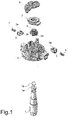
Fig.1 is an exploded perspective view from above of the main components of the system; -
Fig.2 is an enlarged sectional view of the system in the assembled condition and with the latches in contact with the pivot; -
Fig.3 is a view similar to the previous one with the latches disengaged from the pivot; -
Fig.4 is a top plan view of the system in the condition ofFig.2 with the upper elements removed for clarity; and -
Fig.5 is a view similar to the previous one with the system in the condition ofFig.3 . - Referring to the above figures there is seen that a quick connect/disconnect system of a revolving sprinkler according to the invention comprises a hollow pivot 1 mounted on a supply pipe (not shown) and provided with a terminal portion with a
cylindrical shape 1a surmounted by a frusto-conical end shape 1b, whose larger base is adjacent to saidcylindrical shape 1a and has a diameter larger than it so as to form an undercut. In the figures there is shown in particular a connect/disconnect system for a sprinkler that is fed from below, but it is clear that what is said also applies to a sprinkler that is fed from above, i.e. with pivot 1 facing down. - The sprinkler is pivoted on pivot 1 by means of a
hub 2 which internally accommodates at least twolatches 3 sliding radially with respect to the longitudinal axis of pivot 1 in correspondence with the cylindrical shape 1a. Saidlatches 3 are preferably arranged at equidistant positions along the perimeter ofhub 2, and are biased towards the longitudinal axis of pivot 1 bycorresponding springs 4 so as to engage the undercut formed in the terminal portion of pivot 1.Hub 2 also accommodates arotor 5 which is rotatable with respect thereto and in contact with the upper faces of thesliding latches 3, in particular withprojections 3a formed on said upper faces. -
Rotor 5 is shaped withcam profiles 5a in the parts in contact with saidprojections 3a in such a way that its rotation in a given direction (clockwise in the example shown) moves thesliding latches 3 away from the axis of pivot 1 up to a distance greater than the radius of the larger base of the frusto-conical shape 1b, so thatlatches 3 are disengaged from pivot 1 (Fig.3 ).Rotor 5 is also made integral with alever 6 external tohub 2, passing through acover 7 of the hub, so as to allow an operator to rotaterotor 5 by acting onlever 6 with a rotation in the horizontal plane. - In the light of the description above, it is readily understood how the sprinkler connect/disconnect system according to the present invention achieves the desired results of low cost, strength and ease of removal and repositioning of the sprinkler since a limited rotation of lever 6 (of about 20° in the illustrated example) is sufficient to turn
rotor 5 that pushes with thecam profiles 5a onprojections 3a overcoming the resistance ofsprings 4 and moves thesliding latches 3 away from pivot 1 enough to disengage the sprinkler, which can thus be easily removed using only one hand. Note that the movement oflatches 3 is a smooth sliding linear motion since they are received in suitable guides formed inhub 2 and retained therein bycover 7, and that the release stroke ofrotor 5 is preferably defined byend stops 2a formed onhub 2. - So that the sprinkler can be repositioned with great ease and speed simply by pressing it on pivot 1, instead of having to act on
lever 6 also in the connection phase,latches 3 preferably have a lowerbeveled profile 3b that cooperates with the frusto-conical shape 1b to transform the operator's vertical push into a horizontal push for the compression ofsprings 4. In this way,latches 3 move back until they overcome the bottom larger base of the frusto-conical shape 1b, after whichsprings 4 bring them into contact with thecylindrical shape 1a so thatlatches 3 are once again engaged in the undercut of pivot 1. - Note also that
latches 3 are also preferably provided with a frontalconcave profile 3c which corresponds to thecylindrical shape 1a, so as to maximize the surface area of engagement with pivot 1 to give greater stability and solidity to the coupling. - It is clear that the above-described and illustrated embodiment of the sprinkler connect/disconnect system according to the invention is just an example susceptible of various modifications. In particular, the exact number, shape and arrangement of
latches 3 and of the relevant elastic bias means (springs 4 or equivalent) can vary somewhat depending on the specific manufacturing needs as long as the general structure shown above is maintained. Obviously the seats inhub 2 and thecam profiles 5a ofrotor 5 will be modified accordingly on the basis oflatches 3.
Claims (7)
- A connect/disconnect system of a revolving sprinkler of a dishwasher, wherein the sprinkler comprises an elongated tubular body that is centrally pivotable on a hollow pivot (1) fitted at the outlet of a water supply duct of the dishwasher and having a vertical axis corresponding to the axis of rotation of the sprinkler, characterized in that said hollow pivot (1) has a terminal portion with a cylindrical shape (1a) surmounted by a frusto-conical end shape (1b) having a larger base adjacent to said cylindrical shape (1a) and of a diameter greater than it, and in that said revolving sprinkler is pivoted on the hollow pivot (1) by means of a hub (2) that accommodates at least two latches (3) sliding radially with respect to the longitudinal axis of the hollow pivot (1) in correspondence with its cylindrical shape (1a) and biased towards said longitudinal axis by corresponding elastic means (4), said hub (2) also accomodating a rotor (5) in contact with said latches (3) and shaped in such a way that its rotation in a given direction moves the latches (3) away from the longitudinal axis of the pivot (1) up to a distance greater than the radius of said larger base of the frusto-conical shape (1b), said rotor (5) being provided with a gripping member (6) external to the hub (2).
- System according to claim 1, characterized in that the rotor (5) is in contact with projections (3a) formed on the upper faces of the latches (3), the rotor (5) being shaped with cam profiles (5a) in the parts in contact with said projections (3a).
- System according to claim 1 or 2, characterized in that the latches (3) have a lower beveled profile (3b) which cooperates with the frusto-conical shape (1b) of the pivot (1).
- System according to any of the preceding claims, characterized in that the latches (3) are provided with a frontal concave profile (3c) which corresponds to the cylindrical shape (1a) of the pivot (1).
- System according to any of the preceding claims, characterized in that the gripping member (6) of the rotor (5) is a lever connected to the rotor (5) passing through a cover (7) of the hub (2).
- System according to any of the preceding claims, characterized in that the release stroke of the rotor (5) is defined by end stops (2a) formed on the hub (2).
- System according to any of the preceding claims, characterized in that the latches (3) are arranged at equidistant positions along the perimeter of the hub (2).
Priority Applications (2)
| Application Number | Priority Date | Filing Date | Title |
|---|---|---|---|
| PL16425037T PL3241479T3 (en) | 2016-05-02 | 2016-05-02 | Connect/disconnect arrangement for revolving sprinklers of dishwashers |
| EP16425037.5A EP3241479B1 (en) | 2016-05-02 | 2016-05-02 | Connect/disconnect arrangement for revolving sprinklers of dishwashers |
Applications Claiming Priority (1)
| Application Number | Priority Date | Filing Date | Title |
|---|---|---|---|
| EP16425037.5A EP3241479B1 (en) | 2016-05-02 | 2016-05-02 | Connect/disconnect arrangement for revolving sprinklers of dishwashers |
Publications (2)
| Publication Number | Publication Date |
|---|---|
| EP3241479A1 EP3241479A1 (en) | 2017-11-08 |
| EP3241479B1 true EP3241479B1 (en) | 2018-07-11 |
Family
ID=56137265
Family Applications (1)
| Application Number | Title | Priority Date | Filing Date |
|---|---|---|---|
| EP16425037.5A Active EP3241479B1 (en) | 2016-05-02 | 2016-05-02 | Connect/disconnect arrangement for revolving sprinklers of dishwashers |
Country Status (2)
| Country | Link |
|---|---|
| EP (1) | EP3241479B1 (en) |
| PL (1) | PL3241479T3 (en) |
Families Citing this family (3)
| Publication number | Priority date | Publication date | Assignee | Title |
|---|---|---|---|---|
| DE102018112750A1 (en) * | 2018-05-29 | 2019-12-05 | Miele & Cie. Kg | Device for the rotatable mounting of a spray arm |
| DE102019121174B4 (en) * | 2019-08-06 | 2022-08-04 | Winterhalter Gastronom Gmbh | Device for attaching a rinsing arm in a dishwasher |
| DE102020128326B3 (en) | 2020-10-28 | 2022-04-28 | Winterhalter Product & Technology GmbH | Device for transmitting a torque with a drivable shaft for a dishwasher and rinsing arm for a dishwasher |
Citations (13)
| Publication number | Priority date | Publication date | Assignee | Title |
|---|---|---|---|---|
| DE1231397B (en) | 1963-03-26 | 1966-12-29 | Siemens Elektrogeraete Gmbh | Storage of a rotatable spray arm (nozzle carrier) on a liquid feed pipe in a dishwasher |
| US4869428A (en) | 1988-08-08 | 1989-09-26 | Jackson Products Company | Hand actuated connect/disconnect spray arm arrangement for a dishwasher |
| EP0335791A1 (en) | 1988-04-01 | 1989-10-04 | Esswein S.A. | Seal for liquids in an appliance with rotating parts and appliance with rotating parts provided with this seal |
| US5211190A (en) | 1991-12-09 | 1993-05-18 | Maytag Corporation | Wash arm attachment |
| US5725002A (en) | 1996-07-24 | 1998-03-10 | Tca, Inc. | Dish washing machine having interchangeable top and bottom spray arms |
| US6371138B1 (en) | 1997-08-28 | 2002-04-16 | Hoshizaki Denki Kabushiki Kaisha | Nozzle structure for dish washer |
| US20060054204A1 (en) | 2004-09-14 | 2006-03-16 | Fischer David L | Warewash machine arm mount assembly |
| DE102009006163A1 (en) | 2009-01-26 | 2010-07-29 | Meiko Maschinenbau Gmbh & Co. Kg | Cleaning device for cleaning tablewares in e.g. industrial application, has cleaning nozzle rotatably mounted and including pivot bearing designed such that inner surface slides on outer surface by rotating bearing |
| DE102009057461A1 (en) | 2009-12-08 | 2011-08-18 | Simmoteit, Robert, Dr., 72414 | Flushing device for treating aqueous liquid in e.g. medical laboratory, has product cleaning part provided in cleaning machine and ultrasonoscope for organizing sink over local mediums supply in strainer basket |
| WO2013122893A1 (en) | 2012-02-14 | 2013-08-22 | Premark Feg L.L.C. | Warewash machine with removable rotating arm and related method |
| CN203677025U (en) | 2014-01-21 | 2014-07-02 | 美的集团股份有限公司 | Dish-washing machine water spraying component and dish-washing machine |
| DE202014105113U1 (en) | 2014-10-27 | 2014-11-03 | Illinois Tool Works Inc. | Dishwasher system for dishwasher |
| CN205094353U (en) | 2015-10-13 | 2016-03-23 | 佛山市顺德区美的洗涤电器制造有限公司 | A spray arm subassembly for dish washer |
-
2016
- 2016-05-02 EP EP16425037.5A patent/EP3241479B1/en active Active
- 2016-05-02 PL PL16425037T patent/PL3241479T3/en unknown
Patent Citations (13)
| Publication number | Priority date | Publication date | Assignee | Title |
|---|---|---|---|---|
| DE1231397B (en) | 1963-03-26 | 1966-12-29 | Siemens Elektrogeraete Gmbh | Storage of a rotatable spray arm (nozzle carrier) on a liquid feed pipe in a dishwasher |
| EP0335791A1 (en) | 1988-04-01 | 1989-10-04 | Esswein S.A. | Seal for liquids in an appliance with rotating parts and appliance with rotating parts provided with this seal |
| US4869428A (en) | 1988-08-08 | 1989-09-26 | Jackson Products Company | Hand actuated connect/disconnect spray arm arrangement for a dishwasher |
| US5211190A (en) | 1991-12-09 | 1993-05-18 | Maytag Corporation | Wash arm attachment |
| US5725002A (en) | 1996-07-24 | 1998-03-10 | Tca, Inc. | Dish washing machine having interchangeable top and bottom spray arms |
| US6371138B1 (en) | 1997-08-28 | 2002-04-16 | Hoshizaki Denki Kabushiki Kaisha | Nozzle structure for dish washer |
| US20060054204A1 (en) | 2004-09-14 | 2006-03-16 | Fischer David L | Warewash machine arm mount assembly |
| DE102009006163A1 (en) | 2009-01-26 | 2010-07-29 | Meiko Maschinenbau Gmbh & Co. Kg | Cleaning device for cleaning tablewares in e.g. industrial application, has cleaning nozzle rotatably mounted and including pivot bearing designed such that inner surface slides on outer surface by rotating bearing |
| DE102009057461A1 (en) | 2009-12-08 | 2011-08-18 | Simmoteit, Robert, Dr., 72414 | Flushing device for treating aqueous liquid in e.g. medical laboratory, has product cleaning part provided in cleaning machine and ultrasonoscope for organizing sink over local mediums supply in strainer basket |
| WO2013122893A1 (en) | 2012-02-14 | 2013-08-22 | Premark Feg L.L.C. | Warewash machine with removable rotating arm and related method |
| CN203677025U (en) | 2014-01-21 | 2014-07-02 | 美的集团股份有限公司 | Dish-washing machine water spraying component and dish-washing machine |
| DE202014105113U1 (en) | 2014-10-27 | 2014-11-03 | Illinois Tool Works Inc. | Dishwasher system for dishwasher |
| CN205094353U (en) | 2015-10-13 | 2016-03-23 | 佛山市顺德区美的洗涤电器制造有限公司 | A spray arm subassembly for dish washer |
Also Published As
| Publication number | Publication date |
|---|---|
| PL3241479T3 (en) | 2018-11-30 |
| EP3241479A1 (en) | 2017-11-08 |
Similar Documents
| Publication | Publication Date | Title |
|---|---|---|
| EP3241479B1 (en) | Connect/disconnect arrangement for revolving sprinklers of dishwashers | |
| EP3287062B1 (en) | Spraying arm assembly for dishwasher and dishwasher having same | |
| EP2651281B1 (en) | Floor cleaning machine | |
| US5211190A (en) | Wash arm attachment | |
| US10075126B2 (en) | Apparatus for cleaning surfaces | |
| US2726666A (en) | Dishwasher | |
| CN104644096A (en) | Dish washing machine | |
| KR102334614B1 (en) | Dish Washer | |
| CN106137075B (en) | Dishwasher top spray assembly and dishwasher | |
| EP3900605A1 (en) | Dish-washing machine and spraying mechanism | |
| WO2013064989A1 (en) | Jet diffuser with quick- replaceable nozzle for irrigation systems | |
| JP2015506810A (en) | Article washer having a removable rotating arm and associated method | |
| EP3266361B1 (en) | Spray arm assembly for dishwasher, and dishwasher | |
| CN203182834U (en) | Mist-spraying stretchy type multi-functional window wiper | |
| KR102614488B1 (en) | Dish Washer | |
| CN214160289U (en) | Visual injection type online dispenser | |
| EP3703547B1 (en) | Spray arm assembly | |
| JP6501244B2 (en) | Telescopic cleaner | |
| CN109674414B (en) | Washing apparatus | |
| KR20050037363A (en) | A washing arm for a dish-washing machine | |
| CN218458060U (en) | Kettle dismouting structure of water spray mop | |
| EP3618680B1 (en) | A dishwasher comprising a water spray nozzle | |
| CN104738993A (en) | Special brush for automobile | |
| US9227206B2 (en) | Sprinkler structure | |
| CN215650961U (en) | Spraying device and dish washing machine with same |
Legal Events
| Date | Code | Title | Description |
|---|---|---|---|
| PUAI | Public reference made under article 153(3) epc to a published international application that has entered the european phase |
Free format text: ORIGINAL CODE: 0009012 |
|
| STAA | Information on the status of an ep patent application or granted ep patent |
Free format text: STATUS: REQUEST FOR EXAMINATION WAS MADE |
|
| 17P | Request for examination filed |
Effective date: 20161202 |
|
| AK | Designated contracting states |
Kind code of ref document: A1 Designated state(s): AL AT BE BG CH CY CZ DE DK EE ES FI FR GB GR HR HU IE IS IT LI LT LU LV MC MK MT NL NO PL PT RO RS SE SI SK SM TR |
|
| AX | Request for extension of the european patent |
Extension state: BA ME |
|
| GRAP | Despatch of communication of intention to grant a patent |
Free format text: ORIGINAL CODE: EPIDOSNIGR1 |
|
| STAA | Information on the status of an ep patent application or granted ep patent |
Free format text: STATUS: GRANT OF PATENT IS INTENDED |
|
| INTG | Intention to grant announced |
Effective date: 20171220 |
|
| GRAS | Grant fee paid |
Free format text: ORIGINAL CODE: EPIDOSNIGR3 |
|
| GRAA | (expected) grant |
Free format text: ORIGINAL CODE: 0009210 |
|
| STAA | Information on the status of an ep patent application or granted ep patent |
Free format text: STATUS: THE PATENT HAS BEEN GRANTED |
|
| AK | Designated contracting states |
Kind code of ref document: B1 Designated state(s): AL AT BE BG CH CY CZ DE DK EE ES FI FR GB GR HR HU IE IS IT LI LT LU LV MC MK MT NL NO PL PT RO RS SE SI SK SM TR |
|
| REG | Reference to a national code |
Ref country code: GB Ref legal event code: FG4D |
|
| REG | Reference to a national code |
Ref country code: CH Ref legal event code: EP |
|
| REG | Reference to a national code |
Ref country code: AT Ref legal event code: REF Ref document number: 1016044 Country of ref document: AT Kind code of ref document: T Effective date: 20180715 |
|
| REG | Reference to a national code |
Ref country code: IE Ref legal event code: FG4D |
|
| REG | Reference to a national code |
Ref country code: DE Ref legal event code: R096 Ref document number: 602016004035 Country of ref document: DE |
|
| REG | Reference to a national code |
Ref country code: NL Ref legal event code: FP |
|
| REG | Reference to a national code |
Ref country code: LT Ref legal event code: MG4D |
|
| REG | Reference to a national code |
Ref country code: AT Ref legal event code: MK05 Ref document number: 1016044 Country of ref document: AT Kind code of ref document: T Effective date: 20180711 |
|
| PG25 | Lapsed in a contracting state [announced via postgrant information from national office to epo] |
Ref country code: AT Free format text: LAPSE BECAUSE OF FAILURE TO SUBMIT A TRANSLATION OF THE DESCRIPTION OR TO PAY THE FEE WITHIN THE PRESCRIBED TIME-LIMIT Effective date: 20180711 Ref country code: BG Free format text: LAPSE BECAUSE OF FAILURE TO SUBMIT A TRANSLATION OF THE DESCRIPTION OR TO PAY THE FEE WITHIN THE PRESCRIBED TIME-LIMIT Effective date: 20181011 Ref country code: SE Free format text: LAPSE BECAUSE OF FAILURE TO SUBMIT A TRANSLATION OF THE DESCRIPTION OR TO PAY THE FEE WITHIN THE PRESCRIBED TIME-LIMIT Effective date: 20180711 Ref country code: LT Free format text: LAPSE BECAUSE OF FAILURE TO SUBMIT A TRANSLATION OF THE DESCRIPTION OR TO PAY THE FEE WITHIN THE PRESCRIBED TIME-LIMIT Effective date: 20180711 Ref country code: FI Free format text: LAPSE BECAUSE OF FAILURE TO SUBMIT A TRANSLATION OF THE DESCRIPTION OR TO PAY THE FEE WITHIN THE PRESCRIBED TIME-LIMIT Effective date: 20180711 Ref country code: GR Free format text: LAPSE BECAUSE OF FAILURE TO SUBMIT A TRANSLATION OF THE DESCRIPTION OR TO PAY THE FEE WITHIN THE PRESCRIBED TIME-LIMIT Effective date: 20181012 Ref country code: NO Free format text: LAPSE BECAUSE OF FAILURE TO SUBMIT A TRANSLATION OF THE DESCRIPTION OR TO PAY THE FEE WITHIN THE PRESCRIBED TIME-LIMIT Effective date: 20181011 Ref country code: RS Free format text: LAPSE BECAUSE OF FAILURE TO SUBMIT A TRANSLATION OF THE DESCRIPTION OR TO PAY THE FEE WITHIN THE PRESCRIBED TIME-LIMIT Effective date: 20180711 Ref country code: IS Free format text: LAPSE BECAUSE OF FAILURE TO SUBMIT A TRANSLATION OF THE DESCRIPTION OR TO PAY THE FEE WITHIN THE PRESCRIBED TIME-LIMIT Effective date: 20181111 |
|
| PG25 | Lapsed in a contracting state [announced via postgrant information from national office to epo] |
Ref country code: LV Free format text: LAPSE BECAUSE OF FAILURE TO SUBMIT A TRANSLATION OF THE DESCRIPTION OR TO PAY THE FEE WITHIN THE PRESCRIBED TIME-LIMIT Effective date: 20180711 Ref country code: HR Free format text: LAPSE BECAUSE OF FAILURE TO SUBMIT A TRANSLATION OF THE DESCRIPTION OR TO PAY THE FEE WITHIN THE PRESCRIBED TIME-LIMIT Effective date: 20180711 Ref country code: AL Free format text: LAPSE BECAUSE OF FAILURE TO SUBMIT A TRANSLATION OF THE DESCRIPTION OR TO PAY THE FEE WITHIN THE PRESCRIBED TIME-LIMIT Effective date: 20180711 |
|
| REG | Reference to a national code |
Ref country code: DE Ref legal event code: R026 Ref document number: 602016004035 Country of ref document: DE |
|
| PLBI | Opposition filed |
Free format text: ORIGINAL CODE: 0009260 |
|
| PLAB | Opposition data, opponent's data or that of the opponent's representative modified |
Free format text: ORIGINAL CODE: 0009299OPPO |
|
| PLAX | Notice of opposition and request to file observation + time limit sent |
Free format text: ORIGINAL CODE: EPIDOSNOBS2 |
|
| PG25 | Lapsed in a contracting state [announced via postgrant information from national office to epo] |
Ref country code: RO Free format text: LAPSE BECAUSE OF FAILURE TO SUBMIT A TRANSLATION OF THE DESCRIPTION OR TO PAY THE FEE WITHIN THE PRESCRIBED TIME-LIMIT Effective date: 20180711 Ref country code: CZ Free format text: LAPSE BECAUSE OF FAILURE TO SUBMIT A TRANSLATION OF THE DESCRIPTION OR TO PAY THE FEE WITHIN THE PRESCRIBED TIME-LIMIT Effective date: 20180711 Ref country code: EE Free format text: LAPSE BECAUSE OF FAILURE TO SUBMIT A TRANSLATION OF THE DESCRIPTION OR TO PAY THE FEE WITHIN THE PRESCRIBED TIME-LIMIT Effective date: 20180711 Ref country code: ES Free format text: LAPSE BECAUSE OF FAILURE TO SUBMIT A TRANSLATION OF THE DESCRIPTION OR TO PAY THE FEE WITHIN THE PRESCRIBED TIME-LIMIT Effective date: 20180711 |
|
| 26 | Opposition filed |
Opponent name: HOBART GMBH Effective date: 20190411 |
|
| R26 | Opposition filed (corrected) |
Opponent name: HOBART GMBH Effective date: 20190411 |
|
| PG25 | Lapsed in a contracting state [announced via postgrant information from national office to epo] |
Ref country code: SK Free format text: LAPSE BECAUSE OF FAILURE TO SUBMIT A TRANSLATION OF THE DESCRIPTION OR TO PAY THE FEE WITHIN THE PRESCRIBED TIME-LIMIT Effective date: 20180711 Ref country code: DK Free format text: LAPSE BECAUSE OF FAILURE TO SUBMIT A TRANSLATION OF THE DESCRIPTION OR TO PAY THE FEE WITHIN THE PRESCRIBED TIME-LIMIT Effective date: 20180711 Ref country code: SM Free format text: LAPSE BECAUSE OF FAILURE TO SUBMIT A TRANSLATION OF THE DESCRIPTION OR TO PAY THE FEE WITHIN THE PRESCRIBED TIME-LIMIT Effective date: 20180711 |
|
| PG25 | Lapsed in a contracting state [announced via postgrant information from national office to epo] |
Ref country code: SI Free format text: LAPSE BECAUSE OF FAILURE TO SUBMIT A TRANSLATION OF THE DESCRIPTION OR TO PAY THE FEE WITHIN THE PRESCRIBED TIME-LIMIT Effective date: 20180711 |
|
| PLBB | Reply of patent proprietor to notice(s) of opposition received |
Free format text: ORIGINAL CODE: EPIDOSNOBS3 |
|
| REG | Reference to a national code |
Ref country code: CH Ref legal event code: PL |
|
| PG25 | Lapsed in a contracting state [announced via postgrant information from national office to epo] |
Ref country code: CH Free format text: LAPSE BECAUSE OF NON-PAYMENT OF DUE FEES Effective date: 20190531 Ref country code: LI Free format text: LAPSE BECAUSE OF NON-PAYMENT OF DUE FEES Effective date: 20190531 Ref country code: MC Free format text: LAPSE BECAUSE OF FAILURE TO SUBMIT A TRANSLATION OF THE DESCRIPTION OR TO PAY THE FEE WITHIN THE PRESCRIBED TIME-LIMIT Effective date: 20180711 |
|
| REG | Reference to a national code |
Ref country code: BE Ref legal event code: MM Effective date: 20190531 |
|
| PG25 | Lapsed in a contracting state [announced via postgrant information from national office to epo] |
Ref country code: LU Free format text: LAPSE BECAUSE OF NON-PAYMENT OF DUE FEES Effective date: 20190502 |
|
| PG25 | Lapsed in a contracting state [announced via postgrant information from national office to epo] |
Ref country code: TR Free format text: LAPSE BECAUSE OF FAILURE TO SUBMIT A TRANSLATION OF THE DESCRIPTION OR TO PAY THE FEE WITHIN THE PRESCRIBED TIME-LIMIT Effective date: 20180711 |
|
| PG25 | Lapsed in a contracting state [announced via postgrant information from national office to epo] |
Ref country code: IE Free format text: LAPSE BECAUSE OF NON-PAYMENT OF DUE FEES Effective date: 20190502 |
|
| PG25 | Lapsed in a contracting state [announced via postgrant information from national office to epo] |
Ref country code: BE Free format text: LAPSE BECAUSE OF NON-PAYMENT OF DUE FEES Effective date: 20190531 |
|
| PG25 | Lapsed in a contracting state [announced via postgrant information from national office to epo] |
Ref country code: PT Free format text: LAPSE BECAUSE OF FAILURE TO SUBMIT A TRANSLATION OF THE DESCRIPTION OR TO PAY THE FEE WITHIN THE PRESCRIBED TIME-LIMIT Effective date: 20181111 |
|
| PLCK | Communication despatched that opposition was rejected |
Free format text: ORIGINAL CODE: EPIDOSNREJ1 |
|
| REG | Reference to a national code |
Ref country code: DE Ref legal event code: R100 Ref document number: 602016004035 Country of ref document: DE |
|
| PLBN | Opposition rejected |
Free format text: ORIGINAL CODE: 0009273 |
|
| STAA | Information on the status of an ep patent application or granted ep patent |
Free format text: STATUS: OPPOSITION REJECTED |
|
| 27O | Opposition rejected |
Effective date: 20201218 |
|
| PG25 | Lapsed in a contracting state [announced via postgrant information from national office to epo] |
Ref country code: CY Free format text: LAPSE BECAUSE OF FAILURE TO SUBMIT A TRANSLATION OF THE DESCRIPTION OR TO PAY THE FEE WITHIN THE PRESCRIBED TIME-LIMIT Effective date: 20180711 |
|
| PG25 | Lapsed in a contracting state [announced via postgrant information from national office to epo] |
Ref country code: HU Free format text: LAPSE BECAUSE OF FAILURE TO SUBMIT A TRANSLATION OF THE DESCRIPTION OR TO PAY THE FEE WITHIN THE PRESCRIBED TIME-LIMIT; INVALID AB INITIO Effective date: 20160502 Ref country code: MT Free format text: LAPSE BECAUSE OF FAILURE TO SUBMIT A TRANSLATION OF THE DESCRIPTION OR TO PAY THE FEE WITHIN THE PRESCRIBED TIME-LIMIT Effective date: 20180711 |
|
| PG25 | Lapsed in a contracting state [announced via postgrant information from national office to epo] |
Ref country code: MK Free format text: LAPSE BECAUSE OF FAILURE TO SUBMIT A TRANSLATION OF THE DESCRIPTION OR TO PAY THE FEE WITHIN THE PRESCRIBED TIME-LIMIT Effective date: 20180711 |
|
| P01 | Opt-out of the competence of the unified patent court (upc) registered |
Effective date: 20230606 |
|
| PGFP | Annual fee paid to national office [announced via postgrant information from national office to epo] |
Ref country code: NL Payment date: 20250521 Year of fee payment: 10 |
|
| PGFP | Annual fee paid to national office [announced via postgrant information from national office to epo] |
Ref country code: PL Payment date: 20250425 Year of fee payment: 10 Ref country code: DE Payment date: 20250521 Year of fee payment: 10 |
|
| PGFP | Annual fee paid to national office [announced via postgrant information from national office to epo] |
Ref country code: GB Payment date: 20250521 Year of fee payment: 10 |
|
| PGFP | Annual fee paid to national office [announced via postgrant information from national office to epo] |
Ref country code: IT Payment date: 20250515 Year of fee payment: 10 |
|
| PGFP | Annual fee paid to national office [announced via postgrant information from national office to epo] |
Ref country code: FR Payment date: 20250528 Year of fee payment: 10 |