EP3240498B1 - Automatic filling mechanism and method for a hand-held oral cleaning device - Google Patents
Automatic filling mechanism and method for a hand-held oral cleaning device Download PDFInfo
- Publication number
- EP3240498B1 EP3240498B1 EP15823795.8A EP15823795A EP3240498B1 EP 3240498 B1 EP3240498 B1 EP 3240498B1 EP 15823795 A EP15823795 A EP 15823795A EP 3240498 B1 EP3240498 B1 EP 3240498B1
- Authority
- EP
- European Patent Office
- Prior art keywords
- hand
- chamber
- held
- female
- fluid
- Prior art date
- Legal status (The legal status is an assumption and is not a legal conclusion. Google has not performed a legal analysis and makes no representation as to the accuracy of the status listed.)
- Active
Links
- 230000007246 mechanism Effects 0.000 title claims description 37
- 238000004140 cleaning Methods 0.000 title claims description 17
- 238000000034 method Methods 0.000 title claims description 12
- 239000012530 fluid Substances 0.000 claims description 91
- 238000003032 molecular docking Methods 0.000 claims description 55
- 239000007788 liquid Substances 0.000 claims description 39
- 238000007789 sealing Methods 0.000 claims description 5
- 239000012528 membrane Substances 0.000 claims description 4
- 238000005086 pumping Methods 0.000 claims description 2
- 230000000284 resting effect Effects 0.000 claims 1
- 239000007921 spray Substances 0.000 description 7
- 239000000463 material Substances 0.000 description 5
- XLYOFNOQVPJJNP-UHFFFAOYSA-N water Substances O XLYOFNOQVPJJNP-UHFFFAOYSA-N 0.000 description 5
- 230000001680 brushing effect Effects 0.000 description 3
- 239000002324 mouth wash Substances 0.000 description 3
- 229940051866 mouthwash Drugs 0.000 description 3
- 230000003134 recirculating effect Effects 0.000 description 3
- 230000000845 anti-microbial effect Effects 0.000 description 2
- 230000008901 benefit Effects 0.000 description 2
- 239000013078 crystal Substances 0.000 description 2
- 210000000214 mouth Anatomy 0.000 description 2
- 230000009471 action Effects 0.000 description 1
- 238000005452 bending Methods 0.000 description 1
- 230000015572 biosynthetic process Effects 0.000 description 1
- 238000005429 filling process Methods 0.000 description 1
- 229910052500 inorganic mineral Inorganic materials 0.000 description 1
- 239000011707 mineral Substances 0.000 description 1
- 238000012986 modification Methods 0.000 description 1
- 230000004048 modification Effects 0.000 description 1
Images


Classifications
-
- A—HUMAN NECESSITIES
- A61—MEDICAL OR VETERINARY SCIENCE; HYGIENE
- A61C—DENTISTRY; APPARATUS OR METHODS FOR ORAL OR DENTAL HYGIENE
- A61C17/00—Devices for cleaning, polishing, rinsing or drying teeth, teeth cavities or prostheses; Saliva removers; Dental appliances for receiving spittle
- A61C17/02—Rinsing or air-blowing devices, e.g. using fluid jets or comprising liquid medication
- A61C17/0205—Container filling apparatus
-
- A—HUMAN NECESSITIES
- A61—MEDICAL OR VETERINARY SCIENCE; HYGIENE
- A61C—DENTISTRY; APPARATUS OR METHODS FOR ORAL OR DENTAL HYGIENE
- A61C17/00—Devices for cleaning, polishing, rinsing or drying teeth, teeth cavities or prostheses; Saliva removers; Dental appliances for receiving spittle
- A61C17/02—Rinsing or air-blowing devices, e.g. using fluid jets or comprising liquid medication
- A61C17/0202—Hand-pieces
-
- B—PERFORMING OPERATIONS; TRANSPORTING
- B67—OPENING, CLOSING OR CLEANING BOTTLES, JARS OR SIMILAR CONTAINERS; LIQUID HANDLING
- B67D—DISPENSING, DELIVERING OR TRANSFERRING LIQUIDS, NOT OTHERWISE PROVIDED FOR
- B67D7/00—Apparatus or devices for transferring liquids from bulk storage containers or reservoirs into vehicles or into portable containers, e.g. for retail sale purposes
- B67D7/02—Apparatus or devices for transferring liquids from bulk storage containers or reservoirs into vehicles or into portable containers, e.g. for retail sale purposes for transferring liquids other than fuel or lubricants
- B67D7/0288—Container connection means
- B67D7/0294—Combined with valves
Definitions
- This invention relates generally to hand-held oral cleaning devices using a fluid droplet spray for cleaning of the interproximal areas of the teeth with such a spray.
- a fluid droplet spray for cleaning of the interproximal areas of the teeth with such a spray.
- a stream of high velocity gas is used to create the liquid droplets when liquid is brought into contact with the air stream, such as by a pump or other arrangement.
- One such device for home use is the Philips Sonicare AirFlossTM flosser (manufactured by Koninklijke Philips Electronics, N.V.). While the system is effective, one comment by users is that the chamber of liquid in the hand-held device needs intermittent refilling with water, mouthwash or other fluid, typically after just a few cleanings.
- Document JP H04 306452 A discloses an automatic filling mechanism for a dental hand-held fluid droplet appliance designed to be coupled to a docking and charging station.
- This filling mechanism has a fluid reservoir comprising: a chamber for holding fluid having a door into the chamber and two female ports located there through, a first female port as an inlet for receiving fluid (hot water); and a second female port as a liquid exit interface.
- an automatic filling mechanism for a hand-held fluid droplet appliance for dental cleaning for use in conjunction with a docking and charging station having a reservoir for holding a larger amount of fluid than can be held in the chamber of the hand-held appliance, the mechanism being used for automatically refilling the fluid chamber on the hand-held fluid droplet appliance from the larger reservoir on the docking and charging station when the hand-held appliance is mounted into the docking and charging station.
- an automatic filling mechanism for filling a fluid chamber in a hand-held fluid droplet appliance for dental cleaning designed to be coupled to a docking and charging station having a fluid reservoir.
- the automatic filling mechanism includes a door for the chamber that can be opened, the door having an O-ring around the outer perimeter thereof to prevent leaking of fluid, the door having a first female port therethrough which is an inlet port for receiving liquid from the docking and charging station fluid reservoir into the chamber of the hand-held appliance, and a second female port therethrough that is a liquid and air exit interface, the second female port having a snorkel tube of a snorkel system attached thereto, the snorkel tube having another end that is open and is positioned to be in the top portion of the chamber in the hand-held appliance, and the second female port and the snorkel system being used for exiting air and excess fluid from the chamber as fluid enters the chamber through the first female port from the fluid reservoir in the docking and charging station.
- flexible sealing portions surround the first and second female ports of the automatic filling mechanism to prevent leakage of fluid.
- At least one check valve is connected to at least one of the first or second female ports to control the automatic filling process and provide a shut-off.
- a hard plastic tip is provided at the open end of the snorkel tube to help ensure proper positioning of the snorkel system within the chamber of the hand-held appliance.
- the hard plastic tip at the open end of the snorkel tube has a mechanism to reduce buildup of crystals from the fluid for helping to ensure the snorkel tube does not clog, such as a v-cut shape along the top edge, or one or more holes cut through the plastic tip.
- the chamber has an asymmetrical shape so that the snorkel system can only be inserted in the proper orientation.
- the snorkel system has an internal spring in at least a portion of the snorkel tube to keep the snorkel system properly oriented in the chamber.
- the snorkel system has an air permeable membrane at the open end of the snorkel tube.
- a method of automatically filling a fluid chamber of hand-held fluid droplet appliance for dental cleaning from a fluid reservoir on a docking and charging station is provided.
- the hand-held fluid droplet appliance is configured to be filled when docked in the docking and charging station.
- the hand-held appliance is inserted in a cradle mechanism on the docking and charging station that aligns male ports on the docking and charging station fluid reservoir with female ports on the cover of the fluid chamber of the hand-held fluid droplet appliance.
- one or more safety mechanisms are provided to prevent overfilling of the fluid chamber.
- the present invention pertains to a hand-held fluid droplet appliance 10, as described and shown herein, which produces a spray of liquid droplets which is used to clean the interproximal spaces between teeth.
- Figure 1A shows a hand-held fluid droplet appliance 10 which uses a mechanical system to create a liquid droplet spray for oral cleaning.
- the appliance includes a motor and gear train arrangement 11 powered by a battery 12.
- a control unit 13 is included between the battery 12 and the motor 11 for control of the operation of the hand-held fluid droplet appliance 10.
- the hand-held fluid droplet appliance 10 is turned on or off with a power button 20.
- the power button 20 typically includes an illuminated portion 22 that is used to indicate that the hand-held fluid droplet appliance 10 is on, or is being charged.
- the hand-held fluid droplet appliance 10 includes an elongated nozzle 30 which extends outwardly from the appliance, through which a spray of liquid droplets is directed through an orifice for cleaning action against dental regions of the teeth and other areas of the oral cavity.
- a chamber 40 for water or other liquid is also present in the hand-held appliance. Liquid in the chamber 40 is mixed with air and propelled out through an orifice within the nozzle 30 by means of the motor and gear train arrangement 11.
- An actuator button 15 or similar element is used to actuate the appliance and generate sprays of air and liquid.
- the chamber 40 can be refilled manually by opening the door 42 to the chamber and pouring in liquid from a container or direct from a fluid source (i.e. a water faucet).
- the hand-held fluid droplet appliance 10 can also be filled automatically when connected to a docking and charging station 100 (shown in Figure 2 ) that has a liquid reservoir 110.
- a docking and charging station 100 shown in Figure 2
- a liquid reservoir 110 can also be filled automatically when connected to a docking and charging station 100 (shown in Figure 2 ) that has a liquid reservoir 110.
- Various aspects of the hand-held fluid droplet appliance 10 are disclosed and claimed in other patents and patent applications of the assignee.
- FIG. 1B provides a more detailed view of the door 42 of the chamber 40 in the hand-held fluid droplet appliance 10.
- the door 42 of the present invention includes two female ports 44, 46, each of which is surrounded by a flexible sealing portion 54, 56, to provide a waterproof seal and prevent leaking.
- the dual-port arrangement allows for a recirculating fill flow.
- the first female port 44 is typically a liquid inlet interface which allows liquid to flow into the chamber 40 from the reservoir 110 on the docking and charging station 100
- the second female port 46 is typically the liquid and air exit interface, although other arrangements are also possible.
- the liquid transfer system is described in greater detail below. Because the ports are used for the transfer of liquid, the door 42 on the chamber 40 is further sealed with an O-ring 48 for additional protection against leakage.
- the present invention is intended to enable use of the hand-held fluid droplet appliance 10 with a docking and charging station 100 for automated refilling and charging of the hand-held fluid droplet appliance 10.
- the docking and charging station 100 is shown in Figures 2A through 2C .
- the docking and charging station 100 includes a larger reservoir 110 for holding water, mouthwash, antimicrobial fluids, or other fluids 112, and a pump 104 for pumping liquid out of the docking and charging station reservoir in the base 102 of the docking and charging station 100.
- fluid 112 from the docking and charging station reservoir 110 can be used to fill the chamber 40 on the hand-held fluid droplet appliance 10.
- the docking and charging station 100 has two male ports 144 and 146, which engage two respective female ports 44, 46 in the hand-held appliance, which can be seen in Figs. 1A and 1B .
- the female ports 44, 46, of the hand-held fluid droplet appliance 10 align with the male ports 144, 146 of the docking and charging station 100 and will be mated when the cradle 160 is in the proper position.
- the female ports 44, 46 and the male ports 144, 146 are typically surrounded by a flexible sealing mechanism, O-ring or other device 54, 56 and 154, 156, respectively, that prevents leaking of fluid through the ports.
- the dual-port arrangement allows for a recirculating fill flow.
- the hand-held fluid droplet appliance 10 When the hand-held fluid droplet appliance 10 is docked into the docking and charging station 100, the hand-held appliance is intended to automatically fill the chamber 40 from the reservoir 110 on the docking and charging station 100, assuming there is fluid 112 in the docking and charging station reservoir 110.
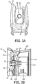
- the main elements of the present invention are the door 42 to the chamber 40 of the hand-held fluid droplet appliance 10 with two female ports 44, 46, as shown in Figure 1B , and a "snorkel system" 80 for the hand-held fluid droplet appliance 10 that is part of the door 42 to the chamber 40, as shown in Figure 3A .
- the two female ports 44, 46 are designed to interface with the two male ports 144 and 146 on the docking and charging station 100 for refilling of the chamber 40 of the hand-held fluid droplet appliance 10.
- the snorkel tube 82 of the snorkel system 80 is connected to the lower female port 46 in the door 42 of hand-held fluid droplet appliance 10.
- the top end 82a of the snorkel tube rests at the top of the chamber 40, an area that is emptied of fluid as the hand-held device is used and fluid is sprayed into the oral cavity.
- the fill interface mechanism consists of the two male ports 144 and 146 on the docking and charging station, which engage the two respective female ports 44, 46 of the present invention in the hand-held fluid droplet appliance 10.
- the dual-port arrangement allows for a recirculating fill flow.
- One female port 44 is a liquid inlet interface with a check valve 55 which allows liquid to flow through the female port 44 when the check valve 55 is open, and it typically has an O-ring or flexible rubber seal 54 around the port to prevent leakage.
- the second female port 46 is the liquid and air exit interface that has a flexible sealing portion 56 to close the port and prevent leakage, and may also have a check valve, micro switch, or other safety mechanism 57 to close the port and prevent leakage or overflow and allow operation only when the hand-held fluid droplet appliance 10 is properly docked to the docking and charging station 100.
- a check valve, micro switch, or other safety mechanism 57 to close the port and prevent leakage or overflow and allow operation only when the hand-held fluid droplet appliance 10 is properly docked to the docking and charging station 100.
- fluid 112 is delivered into the chamber 40 from the reservoir 110 through the liquid inlet interface created when ports 144 and 44 are connected; check valve 55 only allows liquid to flow through the ports 44,144 when the check valve 55 is open, serving as a safety mechanism.
- safety mechanism 57 if present, which can also be a check valve, a micro switch or some other arrangement of device, only allows liquid to flow through the ports 46, 146, when the ports are properly aligned and connected to prevent leakage or overflow.
- the snorkel tube 82 is connected female port 46, the liquid and air exit interface in the door 42 of hand-held fluid droplet appliance 10.
- the top end 82a of the snorkel tube rests at the top of the chamber 40. This allows for air at the top of the chamber to be evacuated while new liquid is being delivered into the lower portion of the chamber 40. This arrangement allows displaced air and over-fill liquid to return to the reservoir 110 in the docking and charging station 100 during filling operations. Therefore, no device is needed for detecting the fluid level in the chamber 40 of the hand-held fluid droplet appliance 10.
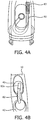
- Figures 4A-4C show various arrangements the snorkel system 80 that help ensure that the snorkel system 80 is properly positioned in the chamber 40, and that the chamber door 42 is not inadvertently inserted upside down, thereby causing misplacement or misalignment of the snorkel tube 82.
- Figure 4A by providing a hard tip 83 of correct dimensions with respect to the opening and chamber size at the top end 82a of the snorkel tube 82, this will help ensure the open tip of the snorkel is always at the top of the chamber and is not accidentally inserted incorrectly.
- the hard tip 83 must be of the correct size that it remains upright and does not fold down the snorkel tube 82 due to the weight of the hard tip, is also large enough to remain at the top of the chamber 40, and does not pull out easily when the chamber door 42 is opened, such as for manual refilling.
- the proper sized hard tip 83, combined with curvature, orientation, and stiffness of the snorkel tube 82 helps to force the top end 82a of the snorkel tube 82 into an upright position at the top of the chamber 40.
- the chamber 40 is asymmetrically sized internally such that a larger portion of it is above the top of the opening to help ensure the snorkel tube 82 cannot be placed in the chamber 40 upside down and the top end 82a of the snorkel tube 82 will always be at the top end of the chamber 40.
- the chamber 40 is asymmetrically sized internally such that a larger portion of it is to one side of the opening, such that the snorkel tube 82 will be naturally biased to fit in one side of the chamber 40, thus further ensuring proper orientation.
- an anti-kink feature for the present invention, as shown in Figure 5 , which can be provided to prevent the snorkel tube 82 from bending and becoming blocked or kinked inside the chamber 40, thereby preventing proper operation.
- an internal spring 85 By inserting an internal spring 85 in the portion of the snorkel tube 82 that should reside in the lower portion of the chamber, it will help to maintain the proper curvature of that portion of the snorkel tube 82, and prevent kinking of the snorkel tube 82.
- the internal spring 85 also has the added benefit of helping to maintain the snorkel tube in the proper position and orientation within the chamber 40.
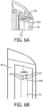
- a mechanism for ensuring the snorkel tube 82 and ports 44, 46, 144, 146 do not clog is desirable, especially when fluid 112 such as mouthwash or antimicrobial liquids, which may have more mineral content, are used in the docking and charging station reservoir 110, as these can dry and crystalize. It was determined that by modifying the top end 82a of the snorkel tube 82, such as the top having a v-cut edge 86 such as shown in Figure 6A , or inserting one or more holes 87 in the top end 82a, as shown in Figure 6B , the flow path of the liquid is broken up, thereby preventing formation of crystals or clogging the flow of liquid. This can help ensure continued efficient operation of the mechanism of the present invention.
- FIG. 7 Another arrangement of the present invention is depicted in Figure 7 , in which an air permeable membrane 90 is attached to the top end 82a of the snorkel tube 82. This will allow the air present in the chamber 40 to be evacuated through the snorkel tube 82 and through the ports 46, 146, but does not let any fluid pass through the membrane 90. Further, this arrangement may eliminate the requirement for a valve or safety device 57 on port 46, because no fluid passes through the port, although one is depicted in Figure 7 . This arrangement may also eliminate the need for other additional overflow or shutoff safety mechanisms in the docking and charging station 100.
- the phrase "at least one,” in reference to a list of one or more elements, should be understood to mean at least one element selected from any one or more of the elements in the list of elements, but not necessarily including at least one of each and every element specifically listed within the list of elements and not excluding any combinations of elements in the list of elements.
- This definition also allows that elements may optionally be present other than the elements specifically identified within the list of elements to which the phrase "at least one" refers, whether related or unrelated to those elements specifically identified.
- inventive embodiments are presented by way of example only and that, within the scope of the appended claims and equivalents thereto, inventive embodiments may be practiced otherwise than as specifically described and claimed.
- inventive embodiments of the present disclosure are directed to each individual feature, system, article, material, kit, and/or method described herein.
Landscapes
- Health & Medical Sciences (AREA)
- Public Health (AREA)
- General Health & Medical Sciences (AREA)
- Dentistry (AREA)
- Epidemiology (AREA)
- Veterinary Medicine (AREA)
- Animal Behavior & Ethology (AREA)
- Life Sciences & Earth Sciences (AREA)
- Engineering & Computer Science (AREA)
- Mechanical Engineering (AREA)
- Dental Tools And Instruments Or Auxiliary Dental Instruments (AREA)
- Infusion, Injection, And Reservoir Apparatuses (AREA)
- Medical Preparation Storing Or Oral Administration Devices (AREA)
- External Artificial Organs (AREA)
- Basic Packing Technique (AREA)
- Supply Of Fluid Materials To The Packaging Location (AREA)
- Filling Of Jars Or Cans And Processes For Cleaning And Sealing Jars (AREA)
Applications Claiming Priority (2)
| Application Number | Priority Date | Filing Date | Title |
|---|---|---|---|
| US201462097261P | 2014-12-29 | 2014-12-29 | |
| PCT/IB2015/059756 WO2016108131A1 (en) | 2014-12-29 | 2015-12-18 | Automatic filling mechanism and method for a hand-held oral cleaning device |
Publications (2)
| Publication Number | Publication Date |
|---|---|
| EP3240498A1 EP3240498A1 (en) | 2017-11-08 |
| EP3240498B1 true EP3240498B1 (en) | 2019-10-23 |
Family
ID=55135463
Family Applications (1)
| Application Number | Title | Priority Date | Filing Date |
|---|---|---|---|
| EP15823795.8A Active EP3240498B1 (en) | 2014-12-29 | 2015-12-18 | Automatic filling mechanism and method for a hand-held oral cleaning device |
Country Status (6)
| Country | Link |
|---|---|
| US (1) | US10357345B2 (zh) |
| EP (1) | EP3240498B1 (zh) |
| JP (1) | JP6684811B2 (zh) |
| CN (1) | CN107106274B (zh) |
| RU (1) | RU2017126974A (zh) |
| WO (1) | WO2016108131A1 (zh) |
Families Citing this family (4)
| Publication number | Priority date | Publication date | Assignee | Title |
|---|---|---|---|---|
| US10610339B2 (en) * | 2015-02-05 | 2020-04-07 | Koninklijke Philips N.V. | Docking and charging station and filling operation for a hand-held oral cleaning device |
| KR102068548B1 (ko) * | 2018-11-09 | 2020-01-22 | 주식회사 에이치앤케어 | 구강 세정 장치 |
| CN109381272A (zh) * | 2018-12-05 | 2019-02-26 | 厦门洁博雅科技有限公司 | 一种洗牙装置 |
| CN109620447B (zh) * | 2019-01-03 | 2024-04-16 | 厦门洁博雅科技有限公司 | 一种便携洗牙装置 |
Family Cites Families (17)
| Publication number | Priority date | Publication date | Assignee | Title |
|---|---|---|---|---|
| JPH04306452A (ja) | 1991-04-03 | 1992-10-29 | Toto Ltd | 多目的吐水装置 |
| US5346324A (en) * | 1991-09-19 | 1994-09-13 | Youti Kuo | Dentifrice dispensing toothbrush with replaceable cartridge |
| US6402410B1 (en) * | 1999-01-13 | 2002-06-11 | Philips Oral Healthcare | Fluid-dispensing and refilling system for a power toothbrush |
| ATE397422T1 (de) * | 2001-02-12 | 2008-06-15 | Koninkl Philips Electronics Nv | Schallantriebs-zahnbürste mit mehreren behältern |
| US6622333B1 (en) * | 2002-09-04 | 2003-09-23 | Rehco, Llc | Pneumatic-operated toothbrush |
| US7080980B2 (en) * | 2003-07-03 | 2006-07-25 | Michael Klupt | Dental hygiene device |
| US20050271531A1 (en) * | 2004-06-03 | 2005-12-08 | Brown William R Jr | Oral care device |
| US8317424B2 (en) * | 2004-06-03 | 2012-11-27 | The Gillette Company | Oral care device |
| US20050272001A1 (en) * | 2004-06-03 | 2005-12-08 | Blain Christopher C | Oral care device |
| US20060078844A1 (en) * | 2004-10-07 | 2006-04-13 | Goldman Paul D | Oral care systems, oral care devices and methods of use |
| TW200934446A (en) * | 2007-10-22 | 2009-08-16 | Colgate Palmolive Co | Oral care implement with air flossing system |
| US9308064B2 (en) * | 2010-07-26 | 2016-04-12 | Johnson & Johnson Consumer Inc. | Devices and methods for collecting and analyzing fluid samples from the oral cavity |
| CN203061499U (zh) * | 2013-01-28 | 2013-07-17 | 李增兴 | 超声波喷洗机 |
| KR101410048B1 (ko) | 2013-03-21 | 2014-06-20 | 안승희 | 구강살균세정기 |
| US9980793B2 (en) * | 2013-11-27 | 2018-05-29 | Water Pik, Inc. | Oral hygiene system |
| EP3241266A1 (en) * | 2014-12-29 | 2017-11-08 | Koninklijke Philips N.V. | Airfloss docking station charge detection |
| US10610339B2 (en) * | 2015-02-05 | 2020-04-07 | Koninklijke Philips N.V. | Docking and charging station and filling operation for a hand-held oral cleaning device |
-
2015
- 2015-12-18 CN CN201580071530.8A patent/CN107106274B/zh active Active
- 2015-12-18 US US15/540,104 patent/US10357345B2/en active Active
- 2015-12-18 EP EP15823795.8A patent/EP3240498B1/en active Active
- 2015-12-18 WO PCT/IB2015/059756 patent/WO2016108131A1/en active Application Filing
- 2015-12-18 RU RU2017126974A patent/RU2017126974A/ru unknown
- 2015-12-18 JP JP2017534698A patent/JP6684811B2/ja active Active
Non-Patent Citations (1)
| Title |
|---|
| None * |
Also Published As
| Publication number | Publication date |
|---|---|
| US20170367800A1 (en) | 2017-12-28 |
| RU2017126974A (ru) | 2019-01-31 |
| EP3240498A1 (en) | 2017-11-08 |
| JP6684811B2 (ja) | 2020-04-22 |
| JP2018500128A (ja) | 2018-01-11 |
| WO2016108131A1 (en) | 2016-07-07 |
| CN107106274B (zh) | 2021-03-26 |
| CN107106274A (zh) | 2017-08-29 |
| US10357345B2 (en) | 2019-07-23 |
Similar Documents
| Publication | Publication Date | Title |
|---|---|---|
| EP3240498B1 (en) | Automatic filling mechanism and method for a hand-held oral cleaning device | |
| EP3253328B1 (en) | Docking and charging station and filling operation for a hand-held oral cleaning device | |
| CN113490469B (zh) | 用于口腔护理器具中的盒和基部单元 | |
| JP5924415B2 (ja) | 口腔洗浄装置 | |
| AU2019356032B2 (en) | Pump-activated feeding container | |
| CN108778084B (zh) | 用于在医疗过程中使用的盖和管组 | |
| BR112018008761B1 (pt) | Sistema de distribuição recarregável, inserto de adaptação, e, pacote de produto recarregável | |
| EP2991536B1 (en) | Container | |
| JP5307600B2 (ja) | 液体吐出容器 | |
| JP4982263B2 (ja) | ディスペンサ | |
| JP2017159955A (ja) | 流体吐出具 | |
| IT202100004736A1 (it) | Connettore per erogatore di fluidi | |
| JP2023039060A (ja) | ボトルキャップアダプター及びこのボトルキャップアダプターを備えたボトル並びにこのボトルを利用可能なウォーターサーバ | |
| JP2005230595A (ja) | 噴霧器 |
Legal Events
| Date | Code | Title | Description |
|---|---|---|---|
| STAA | Information on the status of an ep patent application or granted ep patent |
Free format text: STATUS: THE INTERNATIONAL PUBLICATION HAS BEEN MADE |
|
| PUAI | Public reference made under article 153(3) epc to a published international application that has entered the european phase |
Free format text: ORIGINAL CODE: 0009012 |
|
| STAA | Information on the status of an ep patent application or granted ep patent |
Free format text: STATUS: REQUEST FOR EXAMINATION WAS MADE |
|
| 17P | Request for examination filed |
Effective date: 20170731 |
|
| AK | Designated contracting states |
Kind code of ref document: A1 Designated state(s): AL AT BE BG CH CY CZ DE DK EE ES FI FR GB GR HR HU IE IS IT LI LT LU LV MC MK MT NL NO PL PT RO RS SE SI SK SM TR |
|
| AX | Request for extension of the european patent |
Extension state: BA ME |
|
| DAV | Request for validation of the european patent (deleted) | ||
| DAX | Request for extension of the european patent (deleted) | ||
| GRAP | Despatch of communication of intention to grant a patent |
Free format text: ORIGINAL CODE: EPIDOSNIGR1 |
|
| STAA | Information on the status of an ep patent application or granted ep patent |
Free format text: STATUS: GRANT OF PATENT IS INTENDED |
|
| GRAJ | Information related to disapproval of communication of intention to grant by the applicant or resumption of examination proceedings by the epo deleted |
Free format text: ORIGINAL CODE: EPIDOSDIGR1 |
|
| STAA | Information on the status of an ep patent application or granted ep patent |
Free format text: STATUS: REQUEST FOR EXAMINATION WAS MADE |
|
| INTG | Intention to grant announced |
Effective date: 20190402 |
|
| GRAP | Despatch of communication of intention to grant a patent |
Free format text: ORIGINAL CODE: EPIDOSNIGR1 |
|
| STAA | Information on the status of an ep patent application or granted ep patent |
Free format text: STATUS: GRANT OF PATENT IS INTENDED |
|
| INTC | Intention to grant announced (deleted) | ||
| INTG | Intention to grant announced |
Effective date: 20190510 |
|
| GRAS | Grant fee paid |
Free format text: ORIGINAL CODE: EPIDOSNIGR3 |
|
| GRAA | (expected) grant |
Free format text: ORIGINAL CODE: 0009210 |
|
| STAA | Information on the status of an ep patent application or granted ep patent |
Free format text: STATUS: THE PATENT HAS BEEN GRANTED |
|
| AK | Designated contracting states |
Kind code of ref document: B1 Designated state(s): AL AT BE BG CH CY CZ DE DK EE ES FI FR GB GR HR HU IE IS IT LI LT LU LV MC MK MT NL NO PL PT RO RS SE SI SK SM TR |
|
| REG | Reference to a national code |
Ref country code: GB Ref legal event code: FG4D |
|
| REG | Reference to a national code |
Ref country code: CH Ref legal event code: EP |
|
| REG | Reference to a national code |
Ref country code: IE Ref legal event code: FG4D |
|
| REG | Reference to a national code |
Ref country code: DE Ref legal event code: R096 Ref document number: 602015040442 Country of ref document: DE |
|
| REG | Reference to a national code |
Ref country code: AT Ref legal event code: REF Ref document number: 1192806 Country of ref document: AT Kind code of ref document: T Effective date: 20191115 |
|
| REG | Reference to a national code |
Ref country code: NL Ref legal event code: MP Effective date: 20191023 |
|
| REG | Reference to a national code |
Ref country code: LT Ref legal event code: MG4D |
|
| RAP2 | Party data changed (patent owner data changed or rights of a patent transferred) |
Owner name: KONINKLIJKE PHILIPS N.V. |
|
| PG25 | Lapsed in a contracting state [announced via postgrant information from national office to epo] |
Ref country code: SE Free format text: LAPSE BECAUSE OF FAILURE TO SUBMIT A TRANSLATION OF THE DESCRIPTION OR TO PAY THE FEE WITHIN THE PRESCRIBED TIME-LIMIT Effective date: 20191023 Ref country code: LV Free format text: LAPSE BECAUSE OF FAILURE TO SUBMIT A TRANSLATION OF THE DESCRIPTION OR TO PAY THE FEE WITHIN THE PRESCRIBED TIME-LIMIT Effective date: 20191023 Ref country code: PT Free format text: LAPSE BECAUSE OF FAILURE TO SUBMIT A TRANSLATION OF THE DESCRIPTION OR TO PAY THE FEE WITHIN THE PRESCRIBED TIME-LIMIT Effective date: 20200224 Ref country code: BG Free format text: LAPSE BECAUSE OF FAILURE TO SUBMIT A TRANSLATION OF THE DESCRIPTION OR TO PAY THE FEE WITHIN THE PRESCRIBED TIME-LIMIT Effective date: 20200123 Ref country code: NO Free format text: LAPSE BECAUSE OF FAILURE TO SUBMIT A TRANSLATION OF THE DESCRIPTION OR TO PAY THE FEE WITHIN THE PRESCRIBED TIME-LIMIT Effective date: 20200123 Ref country code: FI Free format text: LAPSE BECAUSE OF FAILURE TO SUBMIT A TRANSLATION OF THE DESCRIPTION OR TO PAY THE FEE WITHIN THE PRESCRIBED TIME-LIMIT Effective date: 20191023 Ref country code: NL Free format text: LAPSE BECAUSE OF FAILURE TO SUBMIT A TRANSLATION OF THE DESCRIPTION OR TO PAY THE FEE WITHIN THE PRESCRIBED TIME-LIMIT Effective date: 20191023 Ref country code: LT Free format text: LAPSE BECAUSE OF FAILURE TO SUBMIT A TRANSLATION OF THE DESCRIPTION OR TO PAY THE FEE WITHIN THE PRESCRIBED TIME-LIMIT Effective date: 20191023 Ref country code: PL Free format text: LAPSE BECAUSE OF FAILURE TO SUBMIT A TRANSLATION OF THE DESCRIPTION OR TO PAY THE FEE WITHIN THE PRESCRIBED TIME-LIMIT Effective date: 20191023 Ref country code: GR Free format text: LAPSE BECAUSE OF FAILURE TO SUBMIT A TRANSLATION OF THE DESCRIPTION OR TO PAY THE FEE WITHIN THE PRESCRIBED TIME-LIMIT Effective date: 20200124 |
|
| PG25 | Lapsed in a contracting state [announced via postgrant information from national office to epo] |
Ref country code: RS Free format text: LAPSE BECAUSE OF FAILURE TO SUBMIT A TRANSLATION OF THE DESCRIPTION OR TO PAY THE FEE WITHIN THE PRESCRIBED TIME-LIMIT Effective date: 20191023 Ref country code: IS Free format text: LAPSE BECAUSE OF FAILURE TO SUBMIT A TRANSLATION OF THE DESCRIPTION OR TO PAY THE FEE WITHIN THE PRESCRIBED TIME-LIMIT Effective date: 20200224 Ref country code: HR Free format text: LAPSE BECAUSE OF FAILURE TO SUBMIT A TRANSLATION OF THE DESCRIPTION OR TO PAY THE FEE WITHIN THE PRESCRIBED TIME-LIMIT Effective date: 20191023 |
|
| PG25 | Lapsed in a contracting state [announced via postgrant information from national office to epo] |
Ref country code: AL Free format text: LAPSE BECAUSE OF FAILURE TO SUBMIT A TRANSLATION OF THE DESCRIPTION OR TO PAY THE FEE WITHIN THE PRESCRIBED TIME-LIMIT Effective date: 20191023 |
|
| REG | Reference to a national code |
Ref country code: DE Ref legal event code: R097 Ref document number: 602015040442 Country of ref document: DE |
|
| PG2D | Information on lapse in contracting state deleted |
Ref country code: IS |
|
| PG25 | Lapsed in a contracting state [announced via postgrant information from national office to epo] |
Ref country code: EE Free format text: LAPSE BECAUSE OF FAILURE TO SUBMIT A TRANSLATION OF THE DESCRIPTION OR TO PAY THE FEE WITHIN THE PRESCRIBED TIME-LIMIT Effective date: 20191023 Ref country code: RO Free format text: LAPSE BECAUSE OF FAILURE TO SUBMIT A TRANSLATION OF THE DESCRIPTION OR TO PAY THE FEE WITHIN THE PRESCRIBED TIME-LIMIT Effective date: 20191023 Ref country code: CZ Free format text: LAPSE BECAUSE OF FAILURE TO SUBMIT A TRANSLATION OF THE DESCRIPTION OR TO PAY THE FEE WITHIN THE PRESCRIBED TIME-LIMIT Effective date: 20191023 Ref country code: ES Free format text: LAPSE BECAUSE OF FAILURE TO SUBMIT A TRANSLATION OF THE DESCRIPTION OR TO PAY THE FEE WITHIN THE PRESCRIBED TIME-LIMIT Effective date: 20191023 Ref country code: DK Free format text: LAPSE BECAUSE OF FAILURE TO SUBMIT A TRANSLATION OF THE DESCRIPTION OR TO PAY THE FEE WITHIN THE PRESCRIBED TIME-LIMIT Effective date: 20191023 Ref country code: IS Free format text: LAPSE BECAUSE OF FAILURE TO SUBMIT A TRANSLATION OF THE DESCRIPTION OR TO PAY THE FEE WITHIN THE PRESCRIBED TIME-LIMIT Effective date: 20200223 |
|
| REG | Reference to a national code |
Ref country code: CH Ref legal event code: PL |
|
| REG | Reference to a national code |
Ref country code: AT Ref legal event code: MK05 Ref document number: 1192806 Country of ref document: AT Kind code of ref document: T Effective date: 20191023 |
|
| REG | Reference to a national code |
Ref country code: BE Ref legal event code: MM Effective date: 20191231 |
|
| PLBE | No opposition filed within time limit |
Free format text: ORIGINAL CODE: 0009261 |
|
| STAA | Information on the status of an ep patent application or granted ep patent |
Free format text: STATUS: NO OPPOSITION FILED WITHIN TIME LIMIT |
|
| PG25 | Lapsed in a contracting state [announced via postgrant information from national office to epo] |
Ref country code: SM Free format text: LAPSE BECAUSE OF FAILURE TO SUBMIT A TRANSLATION OF THE DESCRIPTION OR TO PAY THE FEE WITHIN THE PRESCRIBED TIME-LIMIT Effective date: 20191023 Ref country code: MC Free format text: LAPSE BECAUSE OF FAILURE TO SUBMIT A TRANSLATION OF THE DESCRIPTION OR TO PAY THE FEE WITHIN THE PRESCRIBED TIME-LIMIT Effective date: 20191023 Ref country code: IT Free format text: LAPSE BECAUSE OF FAILURE TO SUBMIT A TRANSLATION OF THE DESCRIPTION OR TO PAY THE FEE WITHIN THE PRESCRIBED TIME-LIMIT Effective date: 20191023 Ref country code: SK Free format text: LAPSE BECAUSE OF FAILURE TO SUBMIT A TRANSLATION OF THE DESCRIPTION OR TO PAY THE FEE WITHIN THE PRESCRIBED TIME-LIMIT Effective date: 20191023 |
|
| 26N | No opposition filed |
Effective date: 20200724 |
|
| PG25 | Lapsed in a contracting state [announced via postgrant information from national office to epo] |
Ref country code: LU Free format text: LAPSE BECAUSE OF NON-PAYMENT OF DUE FEES Effective date: 20191218 Ref country code: IE Free format text: LAPSE BECAUSE OF NON-PAYMENT OF DUE FEES Effective date: 20191218 |
|
| PG25 | Lapsed in a contracting state [announced via postgrant information from national office to epo] |
Ref country code: BE Free format text: LAPSE BECAUSE OF NON-PAYMENT OF DUE FEES Effective date: 20191231 Ref country code: SI Free format text: LAPSE BECAUSE OF FAILURE TO SUBMIT A TRANSLATION OF THE DESCRIPTION OR TO PAY THE FEE WITHIN THE PRESCRIBED TIME-LIMIT Effective date: 20191023 Ref country code: CH Free format text: LAPSE BECAUSE OF NON-PAYMENT OF DUE FEES Effective date: 20191231 Ref country code: AT Free format text: LAPSE BECAUSE OF FAILURE TO SUBMIT A TRANSLATION OF THE DESCRIPTION OR TO PAY THE FEE WITHIN THE PRESCRIBED TIME-LIMIT Effective date: 20191023 Ref country code: LI Free format text: LAPSE BECAUSE OF NON-PAYMENT OF DUE FEES Effective date: 20191231 |
|
| PG25 | Lapsed in a contracting state [announced via postgrant information from national office to epo] |
Ref country code: CY Free format text: LAPSE BECAUSE OF FAILURE TO SUBMIT A TRANSLATION OF THE DESCRIPTION OR TO PAY THE FEE WITHIN THE PRESCRIBED TIME-LIMIT Effective date: 20191023 |
|
| PG25 | Lapsed in a contracting state [announced via postgrant information from national office to epo] |
Ref country code: HU Free format text: LAPSE BECAUSE OF FAILURE TO SUBMIT A TRANSLATION OF THE DESCRIPTION OR TO PAY THE FEE WITHIN THE PRESCRIBED TIME-LIMIT; INVALID AB INITIO Effective date: 20151218 Ref country code: MT Free format text: LAPSE BECAUSE OF FAILURE TO SUBMIT A TRANSLATION OF THE DESCRIPTION OR TO PAY THE FEE WITHIN THE PRESCRIBED TIME-LIMIT Effective date: 20191023 |
|
| PGFP | Annual fee paid to national office [announced via postgrant information from national office to epo] |
Ref country code: TR Payment date: 20211207 Year of fee payment: 7 |
|
| PG25 | Lapsed in a contracting state [announced via postgrant information from national office to epo] |
Ref country code: MK Free format text: LAPSE BECAUSE OF FAILURE TO SUBMIT A TRANSLATION OF THE DESCRIPTION OR TO PAY THE FEE WITHIN THE PRESCRIBED TIME-LIMIT Effective date: 20191023 |
|
| PGFP | Annual fee paid to national office [announced via postgrant information from national office to epo] |
Ref country code: GB Payment date: 20231219 Year of fee payment: 9 |
|
| PGFP | Annual fee paid to national office [announced via postgrant information from national office to epo] |
Ref country code: FR Payment date: 20231226 Year of fee payment: 9 |
|
| PGFP | Annual fee paid to national office [announced via postgrant information from national office to epo] |
Ref country code: DE Payment date: 20231227 Year of fee payment: 9 |