EP3240384A1 - Module for electronic control of a lighting and/or signalling device of a vehicle, and method for replacing such a module - Google Patents
Module for electronic control of a lighting and/or signalling device of a vehicle, and method for replacing such a module Download PDFInfo
- Publication number
- EP3240384A1 EP3240384A1 EP17166715.7A EP17166715A EP3240384A1 EP 3240384 A1 EP3240384 A1 EP 3240384A1 EP 17166715 A EP17166715 A EP 17166715A EP 3240384 A1 EP3240384 A1 EP 3240384A1
- Authority
- EP
- European Patent Office
- Prior art keywords
- control module
- housing
- electronic control
- support
- wall
- Prior art date
- Legal status (The legal status is an assumption and is not a legal conclusion. Google has not performed a legal analysis and makes no representation as to the accuracy of the status listed.)
- Granted
Links
- 238000000034 method Methods 0.000 title claims description 6
- 230000011664 signaling Effects 0.000 title description 11
- 238000000605 extraction Methods 0.000 claims description 11
- 230000000295 complement effect Effects 0.000 claims description 2
- 230000002093 peripheral effect Effects 0.000 description 12
- 230000002950 deficient Effects 0.000 description 11
- 238000003780 insertion Methods 0.000 description 5
- 230000037431 insertion Effects 0.000 description 5
- 230000003287 optical effect Effects 0.000 description 3
- 229910001335 Galvanized steel Inorganic materials 0.000 description 2
- 230000006866 deterioration Effects 0.000 description 2
- 239000008397 galvanized steel Substances 0.000 description 2
- 239000000463 material Substances 0.000 description 2
- 238000004026 adhesive bonding Methods 0.000 description 1
- 230000000694 effects Effects 0.000 description 1
- 230000007257 malfunction Effects 0.000 description 1
- 230000001681 protective effect Effects 0.000 description 1
- 230000002441 reversible effect Effects 0.000 description 1
Images


Classifications
-
- B—PERFORMING OPERATIONS; TRANSPORTING
- B60—VEHICLES IN GENERAL
- B60Q—ARRANGEMENT OF SIGNALLING OR LIGHTING DEVICES, THE MOUNTING OR SUPPORTING THEREOF OR CIRCUITS THEREFOR, FOR VEHICLES IN GENERAL
- B60Q1/00—Arrangement of optical signalling or lighting devices, the mounting or supporting thereof or circuits therefor
- B60Q1/0064—Arrangement of optical signalling or lighting devices, the mounting or supporting thereof or circuits therefor with provision for maintenance, e.g. changing the light bulb
-
- F—MECHANICAL ENGINEERING; LIGHTING; HEATING; WEAPONS; BLASTING
- F21—LIGHTING
- F21V—FUNCTIONAL FEATURES OR DETAILS OF LIGHTING DEVICES OR SYSTEMS THEREOF; STRUCTURAL COMBINATIONS OF LIGHTING DEVICES WITH OTHER ARTICLES, NOT OTHERWISE PROVIDED FOR
- F21V5/00—Refractors for light sources
- F21V5/04—Refractors for light sources of lens shape
-
- B—PERFORMING OPERATIONS; TRANSPORTING
- B60—VEHICLES IN GENERAL
- B60Q—ARRANGEMENT OF SIGNALLING OR LIGHTING DEVICES, THE MOUNTING OR SUPPORTING THEREOF OR CIRCUITS THEREFOR, FOR VEHICLES IN GENERAL
- B60Q1/00—Arrangement of optical signalling or lighting devices, the mounting or supporting thereof or circuits therefor
- B60Q1/0088—Details of electrical connections
- B60Q1/0094—Arrangement of electronic circuits separated from the light source, e.g. mounting of housings for starter circuits for discharge lamps
-
- B—PERFORMING OPERATIONS; TRANSPORTING
- B60—VEHICLES IN GENERAL
- B60Q—ARRANGEMENT OF SIGNALLING OR LIGHTING DEVICES, THE MOUNTING OR SUPPORTING THEREOF OR CIRCUITS THEREFOR, FOR VEHICLES IN GENERAL
- B60Q1/00—Arrangement of optical signalling or lighting devices, the mounting or supporting thereof or circuits therefor
- B60Q1/26—Arrangement of optical signalling or lighting devices, the mounting or supporting thereof or circuits therefor the devices being primarily intended to indicate the vehicle, or parts thereof, or to give signals, to other traffic
- B60Q1/34—Arrangement of optical signalling or lighting devices, the mounting or supporting thereof or circuits therefor the devices being primarily intended to indicate the vehicle, or parts thereof, or to give signals, to other traffic for indicating change of drive direction
-
- F—MECHANICAL ENGINEERING; LIGHTING; HEATING; WEAPONS; BLASTING
- F21—LIGHTING
- F21V—FUNCTIONAL FEATURES OR DETAILS OF LIGHTING DEVICES OR SYSTEMS THEREOF; STRUCTURAL COMBINATIONS OF LIGHTING DEVICES WITH OTHER ARTICLES, NOT OTHERWISE PROVIDED FOR
- F21V23/00—Arrangement of electric circuit elements in or on lighting devices
- F21V23/04—Arrangement of electric circuit elements in or on lighting devices the elements being switches
-
- H—ELECTRICITY
- H05—ELECTRIC TECHNIQUES NOT OTHERWISE PROVIDED FOR
- H05B—ELECTRIC HEATING; ELECTRIC LIGHT SOURCES NOT OTHERWISE PROVIDED FOR; CIRCUIT ARRANGEMENTS FOR ELECTRIC LIGHT SOURCES, IN GENERAL
- H05B47/00—Circuit arrangements for operating light sources in general, i.e. where the type of light source is not relevant
- H05B47/10—Controlling the light source
-
- H—ELECTRICITY
- H05—ELECTRIC TECHNIQUES NOT OTHERWISE PROVIDED FOR
- H05K—PRINTED CIRCUITS; CASINGS OR CONSTRUCTIONAL DETAILS OF ELECTRIC APPARATUS; MANUFACTURE OF ASSEMBLAGES OF ELECTRICAL COMPONENTS
- H05K5/00—Casings, cabinets or drawers for electric apparatus
- H05K5/0026—Casings, cabinets or drawers for electric apparatus provided with connectors and printed circuit boards [PCB], e.g. automotive electronic control units
- H05K5/0073—Casings, cabinets or drawers for electric apparatus provided with connectors and printed circuit boards [PCB], e.g. automotive electronic control units having specific features for mounting the housing on an external structure
-
- H—ELECTRICITY
- H05—ELECTRIC TECHNIQUES NOT OTHERWISE PROVIDED FOR
- H05K—PRINTED CIRCUITS; CASINGS OR CONSTRUCTIONAL DETAILS OF ELECTRIC APPARATUS; MANUFACTURE OF ASSEMBLAGES OF ELECTRICAL COMPONENTS
- H05K7/00—Constructional details common to different types of electric apparatus
- H05K7/14—Mounting supporting structure in casing or on frame or rack
- H05K7/1417—Mounting supporting structure in casing or on frame or rack having securing means for mounting boards, plates or wiring boards
-
- B—PERFORMING OPERATIONS; TRANSPORTING
- B60—VEHICLES IN GENERAL
- B60Q—ARRANGEMENT OF SIGNALLING OR LIGHTING DEVICES, THE MOUNTING OR SUPPORTING THEREOF OR CIRCUITS THEREFOR, FOR VEHICLES IN GENERAL
- B60Q2400/00—Special features or arrangements of exterior signal lamps for vehicles
- B60Q2400/30—Daytime running lights [DRL], e.g. circuits or arrangements therefor
-
- F—MECHANICAL ENGINEERING; LIGHTING; HEATING; WEAPONS; BLASTING
- F21—LIGHTING
- F21S—NON-PORTABLE LIGHTING DEVICES; SYSTEMS THEREOF; VEHICLE LIGHTING DEVICES SPECIALLY ADAPTED FOR VEHICLE EXTERIORS
- F21S41/00—Illuminating devices specially adapted for vehicle exteriors, e.g. headlamps
- F21S41/20—Illuminating devices specially adapted for vehicle exteriors, e.g. headlamps characterised by refractors, transparent cover plates, light guides or filters
- F21S41/28—Cover glass
-
- F—MECHANICAL ENGINEERING; LIGHTING; HEATING; WEAPONS; BLASTING
- F21—LIGHTING
- F21S—NON-PORTABLE LIGHTING DEVICES; SYSTEMS THEREOF; VEHICLE LIGHTING DEVICES SPECIALLY ADAPTED FOR VEHICLE EXTERIORS
- F21S43/00—Signalling devices specially adapted for vehicle exteriors, e.g. brake lamps, direction indicator lights or reversing lights
- F21S43/20—Signalling devices specially adapted for vehicle exteriors, e.g. brake lamps, direction indicator lights or reversing lights characterised by refractors, transparent cover plates, light guides or filters
- F21S43/26—Refractors, transparent cover plates, light guides or filters not provided in groups F21S43/235 - F21S43/255
Definitions
- the invention relates to lighting devices and / or signaling of a motor vehicle, and it relates more particularly to the electronic control modules equipping such lighting and / or signaling devices, as well as the means implemented to proceed. replacing a used or defective module.
- an electronic source control module is implanted in the housing of these devices, including in particular a card electronic steering system, otherwise called "driver".
- driver a card electronic steering system
- the electronic control module collects information on external conditions via state sensors, or commands from the driver, and generate control instructions for light sources.
- the electronic control module may for example automatically control the ignition of light sources in the context of the DLR protocol ("daytime running light"), which forces certain vehicles to present lighting elements and / or signaling lighting automatically during the day so as to improve the visibility of the vehicle when driving. It has been clarified that the control module makes it possible to control the switching on and off of the light sources, but it will be understood that it can furthermore manage the power supply voltages of the sources and the light intensity produced by the associated device. .
- the electronic control module is attached inside the housing of the lighting and / or signaling device, and it must be fixed by a reversible connection, in order to be able to disassemble the module of the housing when it is defective and that it is necessary to exchange it.
- Electronic control modules are thus known, arranged in a housing formed in the housing, and which is held in position in this housing by screwing. We understand then that to replace a defective module, it is necessary to unscrew this or these fixing screws, to remove the defective module from its housing to extract it from the housing, then to replace a new module in this same housing and finally to screw one by one each of the screws of fixation. This requires screwing operations and unscrewing in the confined space of the housing, complicated to achieve and time consuming.
- the various components present in the housing including the light sources are not removed when a faulty module has to be exchanged, so that the unscrewing and then the re-screwing is carried out while the sources are in position and they can be damaged in the event of a fall of screw, of screwdrivers, etc.
- An object of the invention is to provide an electronic control module easy to implement, easy to mount in a lighting and / or signaling device housing, and whose replacement in case of malfunction is fast and without risk .
- it seeks to facilitate the extraction of the electronic control modules with respect to the housing in which they are integrated.
- an electronic control module for a light source comprising at least one electronic component support card configured to be received by a first of its edges in a housing, characterized in that the control module present at the adjacent to this first edge a connecting portion comprising at least one rib extending perpendicularly, or substantially perpendicular to the plane defined by the map.
- substantially perpendicular is meant a difference of 1 or 2 ° between the median plane of the rib and the plane defined by the map.
- the invention also relates to a light device, comprising at least one light source housed in a housing and at least one electronic control module according to the invention.
- the term "electronic control module” is intended in particular to cover a device for converting a power supply from a vehicle power supply network into an electrical power supply adapted to the achievement of a desired light function, and possibly to supply the said power supply. electrical power supply adapted to a light source for carrying out said desired light function.
- the invention also relates to a method for replacing an electronic control module arranged inside a light device by being electrically connected to one or more light sources, the electronic control module being housed in a nominal position. in a solidarity support of a wall of a housing of the light device, with at least one rib of the module extending in a groove of the support substantially parallel to said wall.
- a step of electrical disconnection of the light source or sources with the electronic control module to be replaced a step of partially cutting the wall of the housing around the housing, from the outside of the housing, a extraction step of the support relative to the device, the support carrying the module by cooperation of the rib of the module and the groove of the support, a positioning step of a new electronic control module equipped with a support comprising a hood closure means adapting to the opening, an electrical connection step and a step of fixing the closing cap of the new electronic control module on the wall of the housing from outside the housing.
- the wall cut during the extraction step may in particular be precut, for example by a lesser thickness in certain areas of the wall.
- the fixing of the cover can be done in particular by means of clamping screws cooperating with clamping drums arranged on the wall of the housing surrounding the partial cutting area of the wall.
- the positioning step by insertion of the new electronic control module in the opening formed by the cutting of the wall portion can be performed until abutting with the second edge of the electronic card against the trench formed in the inner wall of the casing arranged next to the opening.
- the device 100 of the figure 1 is a vehicle lighting and signaling device, comprising a housing 1, closed by a window 11 to define a reception zone of one or more light modules configured for performing a lighting function and / or signaling.
- a light module comprises at least one light source 12 and an electronic control module 13, the module 13 being connected to the light source 12 by links 14 such as electric cables.
- the electronic control module 13 determines as a function of data that it receives the value of the supply voltage of the light source 12.
- the electronic control module 13 comprises at least one card support 15 of electronic components, substantially flat, from which deploy a bundle of electric cables 14 (visible on the Figures 3 and 5 ).
- the card 15 is covered with a cover 16, serving in particular as a means of protection for the electronic components.
- the card 15 comprises non-illustrated electronic components located on a first face 17 of the card, on which the cover 16 is rigidly fixed.
- the cover 16 has a convex central portion 16a covering the electronic components of the card and delimited by a side wall. 16b device as well that a substantially flat outline 18 pressed against the card extending this peripheral side wall.
- indexing means 19 For the positioning of the cover 16 on the first face 17 of the card 15, one can provide indexing means 19 by cooperation of pins 19a carried by the card 15 with orifices formed in the fingers 19b carried by the cover. The fixing of the lid on the card is then performed by any means, for example by gluing.
- the electronic control module 13 has, at a first end edge 20, a connecting portion 21 configured to cooperate with a support 30 as will be described hereinafter, and a second opposite end edge 22 , a guide portion 23 configured to cooperate with a trench arranged in a wall inside the housing as will be described below.
- the connecting portion 21 comprises at least one rectilinear rib 24, extending perpendicularly, or substantially perpendicularly, to the plane defined by the support card of the electronic components.
- the rib 24 extends over the entire width of the control module 13, that is to say over the entire dimension of the first end edge 20, from one corner to another of the map 15.
- the connecting portion is formed by a rectilinear rib 24 extending substantially perpendicularly the contour 18 of the lid 16.
- the lid may in particular be made of galvanized steel (and for example galvanized steel type DX 54 + Z 100).
- the chosen material makes it possible to make the rib by folding from an edge of the lid 16, being sufficiently rigid to hold when the support is extracted.
- the rectilinear rib 24 can extend an edge of the lid by a fold, so that the connecting portion 21 has an L-shaped shape, with the contour 18 of the lid and the straight rib 24. This rib has the effect of hanging the cover and therefore the entire electronic control module 13 to the support 30.
- the rectilinear rib could be arranged at a constant distance from the first edge of the electronic control module, the profiled shape of the connection portion then being different of the L shape previously described and illustrated by way of example in the figures. In each of these cases, it will be noted that the rectilinear rib 24 extends away from the peripheral lateral face 16b of the cover 16, separated by a planar clearance portion formed by the contour 18.
- the electronic component support card has a first wafer 26, perpendicular to the first 20 and second 22 end edges of the electronic control module 13, which extends axially beyond the first edge and beyond the second edge by forming projecting elements 27, 28 of the control module, among which a first projecting element 27 arranged in the vicinity of the first end edge 20 and the straight rib 24, and a second projecting element 28 arranged in the vicinity of the second opposite end edge 22.
- the electronic control module is configured to cooperate with a housing 29 arranged in a support 30, shown alone in FIG. figure 4 .
- This support 30 comprises a flat surface of rectangular shape with rounded corners and forming a cover 31, and a slide 32 formed of two walls extending perpendicularly an inner face 33 of the cover, so as to be parallel facing each other and define between them the housing 29 to receive the electronic control module 13.
- the slide 32 comprises a groove 34, arranged on the inner face of one of the two walls, being substantially perpendicular to the general direction of the passage defined between the two walls of the slide.
- the groove 34 extends substantially over the entire length of the support 30, and it opens on at least a first side 35 of this support, so that the rectilinear rib 24 of the electronic control module can be inserted into the housing 29 by sliding. in the groove 34 from this first side of the support.
- the groove opens only on one side of the support and the bottom of the groove in the support defines a stop at the insertion of the module 13 into the support in a direction of insertion substantially parallel to the direction. lengthening of the groove.
- the position of the module is maintained by the use of a clamping screw 36 screwed into a bore 36a (visible on the figure 6 ) extending parallel to the insertion direction of the module in the support, the screw head then forming a stop for at least the first protruding element 27 preventing extraction of the module from the support.
- the rectilinear rib 24 is disposed in the groove 34 defining at least partly the housing 29.
- the groove 34 comprises a first wall, here an upper wall, 34a and a second wall, here a bottom wall, 34b connected by a bottom wall 34c of the groove.
- the thickness of the rectilinear rib 24 is dimensioned so that it is opposite the first and second walls 34a, 34b.
- the module 13 can not be separated from the support 30 when a force F (visible on the Figures 6 and 10 ) in a direction perpendicular to that of the rib 24 of the module and the groove 34 of the support.
- a force F visible on the Figures 6 and 10
- the rib 24 is pressed against one or other of the walls 34a, 34b and this contact causes the rib and the module with the movement of the support.
- any type of housing adapted to receive and hold in position the rib 24 of the module is suitable, from the moment when a biasing by a force F as mentioned above does not allow to separate the support 30 of the module 13 .
- the presence of this rectilinear rib in the groove of the support allows the simultaneous manipulation of the support and the electronic control module. This is particularly advantageous when it is desired to perform an extraction of a defective module out of the housing of a light device, as will be described later.
- the support 30 is originally an integral part of the housing 1, in the sense that the support is integral with a wall 2 of the housing.
- the wall 2 in which the support 30 is integrated is the upper wall of the housing, and the force F which is exerted to extract the support and the associated module out of the housing is then essentially vertical, but it will be understood that other orientations could to be provided without departing from the context of the invention, since the arrangement of the rib of the module and the groove of the support is substantially perpendicular to the direction of the force F.
- the cover 31 of the support 30 is formed by the wall 2 of the housing 1, and that the slide 32 protrudes from this wall 2 towards the inside of the housing.
- the cover 31 is delimited in the wall 2 by a precut zone 3 distinct from the rest of the wall 2.
- this precut zone 3 is an area of weakness formed by a smaller thickness of the wall at this point. area than the rest of the wall 2.
- the wall 2 has around this precut zone 3 a boss 37 projecting from the outer face of the wall 2 of the housing. Inside this boss, the wall has a lesser thickness than in the other areas, thus forming the cover 31. As illustrated, the zone of weakness can be accentuated by notches 38 made continuously all around. of the cover or punctually, so that it facilitates the pre-cutting of the cover 31. It will be understood that notches could also be made on the inner face of the wall of the housing.
- the peripheral boss 37 is formed on the wall so that the projection on the wall 2 of each of the elements of the control module 13 and the support 30 is located inside this boss.
- the precut zone is in this way to the right of the electronic control module.
- the electronic control module 13 is disposed in the housing between the housing 29 formed in the support 30, integral with one of the walls 2 delimiting the outer periphery of the housing, and an additional housing 39 formed in a internal wall 40 provided with a trench 41.
- the trench 41 extends parallel to the groove 34 made in the support 30. It opens on at least the first side 42 of the inner wall and is open towards the support 30, so that the openings of the trench 41 and the slideway 32 are facing each other. the absence of the module.
- the trench is defined by two parallel walls and a bottom wall which extends substantially parallel to the groove 34.
- the trench is dimensioned so that the guiding portion 23, arranged at the second end edge 22 of the control module, can be housed therein, at least at the level of the second projecting element 28.
- the electronic control module rests against the bottom wall of the trench and the rectilinear rib is in the illustrated position on the figure 6 , that is to say at a distance from one and the other of the walls of the groove 34 of the support 30.
- the figure 7 illustrates the assembly installed in the housing 1 in the nominal position, that is to say in the operating position.
- the role of the trench 41 is here to facilitate the positioning of the control module 13, both during the initial assembly and during the replacement of defective pilot modules, while allowing to remove the opposite of this trench a defective module, by extraction of the support 30 and with him of the module 13.
- the inner wall 40 and the trench in which the module is housed allow to block the module in rotation and to limit the vibrations thereof.
- the housing 1 of the lighting and / or signaling device is here a plastic housing, injected in a single step, with a fixing zone of the electronic control module comprising the support and its groove, and the inner wall facing the one of the other.
- an electronic component support card and the associated lid are inserted into the slideway 32 of the support 30 and, where appropriate, into the trench 41.
- the elements projecting from the card penetrate into the housing 29 and the additional housing 39 by the first side 35 of the support and by the first side 42 of the inner wall.
- the rectilinear rib 24 inserts into the groove 34 of the support.
- the operator pushes the control module to slide it inside the slideway 32 and the inner wall 40 until the rectilinear rib comes into contact with the bottom of the groove 34.
- control module 13 is rigidly attached to the support 30, in a nominal position.
- the operator can then assemble in the housing the rest of the components, and in particular the optical components, of the light device.
- the operator then pulls on the portion of wall cut, corresponding to the cover 31 of the support 30, and it drives with the cover the entire support and the control module made integral with this translation by the imprisonment of the straight rib module in the groove of the support. Before removing completely from the housing the assembly formed by the support and the module, via the opening in the wall thus cut, the operator disconnects the cables 14 of the defective module.
- this new control module advantageously has a set, formed of a card, of new electronic components and a cover, similar to that which was previously extracted from the housing, while the support differs from the support previously removed, in that the hood is larger.
- the cover 31 comes to rest against the peripheral boss.
- a seal may be provided between the cover and the peripheral boss to seal the housing.
- the new cowl has bores for the passage of fastening screws, here not shown, sized to cooperate with the screw drums 37b to lock in position the new electronic control module.
- the positioning of the new electronic control module can be performed both by abutment of the cover on the peripheral boss, that by abutment of the cap on the screw drums, or by abutment of the second projecting element 28 of the new electronic control module in the trench of the inner wall.
- the introduction of the new module has been achieved with screwing operations made outside the housing, so that it avoids the risk of falling screws or deterioration of the interior of the product via a screwdriver by example. Only an electrical connection operation is necessary inside the housing, that is to say an operation without tools.
- the invention makes it possible to simply replace a defective electronic control module without having to risk the deterioration of optical and / or electronic components present elsewhere in the housing of the light device in which the light is applied. 'invention.
Landscapes
- Engineering & Computer Science (AREA)
- Mechanical Engineering (AREA)
- Microelectronics & Electronic Packaging (AREA)
- General Engineering & Computer Science (AREA)
- Casings For Electric Apparatus (AREA)
- Arrangement Of Elements, Cooling, Sealing, Or The Like Of Lighting Devices (AREA)
Abstract
Un module de pilotage électronique (13) d'une source de lumière comporte au moins une carte (15) support de composants électroniques configurée pour être reçue par un premier de ses bords dans un logement (29). Le module de pilotage présente au voisinage de ce premier bord une portion de connexion (21) comportant au moins une nervure (24) s'étendant perpendiculairement, ou sensiblement perpendiculairement, au plan défini par la carte.An electronic control module (13) of a light source comprises at least one electronic component support card (15) configured to be received by a first of its edges in a housing (29). The control module has in the vicinity of this first edge a connecting portion (21) having at least one rib (24) extending perpendicularly, or substantially perpendicular to the plane defined by the card.
Description
L'invention concerne les dispositifs d'éclairage et/ou de signalisation de véhicule automobile, et elle concerne tout particulièrement les modules de pilotage électronique équipant de tels dispositifs d'éclairage et/ou de signalisation, ainsi que les moyens mis en oeuvre pour procéder au remplacement d'un module usagé ou défectueux.The invention relates to lighting devices and / or signaling of a motor vehicle, and it relates more particularly to the electronic control modules equipping such lighting and / or signaling devices, as well as the means implemented to proceed. replacing a used or defective module.
Notamment pour piloter l'allumage et l'extinction des sources de lumière présentes dans un dispositif d'éclairage et/ou de signalisation de véhicule automobile, on implante dans le boîtier de ces dispositifs un module de pilotage électronique des sources, comprenant notamment une carte de pilotage électronique, autrement appelée « driver ». Une fois cette carte installée dans le boîtier du dispositif, on raccorde les composants électroniques que la carte supporte aux sources de lumière, notamment des diodes électroluminescentes. Le module de pilotage électronique permet alors de recueillir des informations sur les conditions extérieures par l'intermédiaire de capteurs d'état, ou encore des commandes provenant du conducteur, et de générer des instructions de pilotage des sources de lumière. Le module de pilotage électronique pourra par exemple piloter automatiquement l'allumage des sources de lumière dans le cadre du protocole DLR (« daytime running light »), qui oblige certains véhicules à présenter des éléments d'éclairage et/ou de signalisation s'allumant automatiquement dans la journée de manière notamment à améliorer la visibilité du véhicule lorsqu'il roule. Il a été précisé que le module de pilotage permet le pilotage en allumage et en extinction des sources de lumière, mais il sera compris qu'il peut en outre gérer les tensions d'alimentation des sources et l'intensité lumineuse produite par le dispositif associé.In particular for controlling the switching on and off of the light sources present in a lighting and / or signaling device for a motor vehicle, an electronic source control module is implanted in the housing of these devices, including in particular a card electronic steering system, otherwise called "driver". Once this card installed in the device housing, the electronic components that the card supports the light sources, including light emitting diodes. The electronic control module then collects information on external conditions via state sensors, or commands from the driver, and generate control instructions for light sources. The electronic control module may for example automatically control the ignition of light sources in the context of the DLR protocol ("daytime running light"), which forces certain vehicles to present lighting elements and / or signaling lighting automatically during the day so as to improve the visibility of the vehicle when driving. It has been clarified that the control module makes it possible to control the switching on and off of the light sources, but it will be understood that it can furthermore manage the power supply voltages of the sources and the light intensity produced by the associated device. .
Le module de pilotage électronique est rapporté à l'intérieur du boîtier du dispositif d'éclairage et/ou de signalisation, et il doit être fixé par une liaison réversible, afin de pouvoir démonter le module du boîtier lorsqu'il est défectueux et qu'il est nécessaire de l'échanger. On connait ainsi des modules de pilotage électronique disposés dans un logement formé dans le boîtier, et que l'on maintient en position dans ce logement par vissage. On comprend alors que pour remplacer un module défectueux, il convient de dévisser cette ou ces vis de fixation, de retirer le module défectueux de son logement pour l'extraire du boîtier, puis de replacer un module neuf dans ce même logement et enfin de revisser une à une chacune des vis de fixation. Cela nécessite des opérations de vissage et dévissage dans l'espace confiné du boîtier, compliquées à réaliser et chronophages.The electronic control module is attached inside the housing of the lighting and / or signaling device, and it must be fixed by a reversible connection, in order to be able to disassemble the module of the housing when it is defective and that it is necessary to exchange it. Electronic control modules are thus known, arranged in a housing formed in the housing, and which is held in position in this housing by screwing. We understand then that to replace a defective module, it is necessary to unscrew this or these fixing screws, to remove the defective module from its housing to extract it from the housing, then to replace a new module in this same housing and finally to screw one by one each of the screws of fixation. This requires screwing operations and unscrewing in the confined space of the housing, complicated to achieve and time consuming.
Par ailleurs, si l'opération initiale de vissage, pour positionner le module dans le logement à l'origine, est sans risque car le boîtier est alors vide d'autres composants, on comprend que les différents composants présents dans le boîtier, et notamment les sources de lumière, ne sont pas retirés lorsqu'un module défectueux doit être échangé, de sorte que le dévissage puis le revissage s'effectue alors que les sources sont en position et qu'elles peuvent être détériorées en cas de chute de vis, de tournevis, etc..Moreover, if the initial screwing operation, to position the module in the housing at the origin, is without risk because the housing is then empty other components, it is understood that the various components present in the housing, including the light sources are not removed when a faulty module has to be exchanged, so that the unscrewing and then the re-screwing is carried out while the sources are in position and they can be damaged in the event of a fall of screw, of screwdrivers, etc.
Un but de l'invention est de prévoir un module de pilotage électronique facile à mettre en oeuvre, facile à monter dans un boîtier de dispositif d'éclairage et/ou de signalisation, et dont le remplacement en cas de disfonctionnement est rapide et sans risque. On cherche ainsi notamment à faciliter l'extraction des modules de pilotage électronique par rapport au boîtier dans lesquels ils sont intégrés.An object of the invention is to provide an electronic control module easy to implement, easy to mount in a lighting and / or signaling device housing, and whose replacement in case of malfunction is fast and without risk . In particular, it seeks to facilitate the extraction of the electronic control modules with respect to the housing in which they are integrated.
A cet effet, on prévoit un module de pilotage électronique d'une source de lumière comportant au moins une carte support de composants électroniques configurée pour être reçue par un premier de ses bords dans un logement, caractérisé en ce que le module de pilotage présente au voisinage de ce premier bord une portion de connexion comportant au moins une nervure s'étendant perpendiculairement, ou sensiblement perpendiculairement, au plan défini par la carte. Par sensiblement perpendiculaire, on entend un écart de 1 ou 2° entre le plan médian de la nervure et le plan défini par la carte.For this purpose, there is provided an electronic control module for a light source comprising at least one electronic component support card configured to be received by a first of its edges in a housing, characterized in that the control module present at the adjacent to this first edge a connecting portion comprising at least one rib extending perpendicularly, or substantially perpendicular to the plane defined by the map. By substantially perpendicular is meant a difference of 1 or 2 ° between the median plane of the rib and the plane defined by the map.
Ainsi, lorsqu'on souhaite ôter le module de pilotage, on n'a plus besoin de travailler à l'intérieur du boîtier. Il suffit de retirer le support du boîtier. Cette extraction est simple et rapide à effectuer.Thus, when it is desired to remove the control module, it is no longer necessary to work inside the housing. Simply remove the housing bracket. This extraction is simple and quick to perform.
Selon différentes caractéristiques de l'invention, prises seules ou en combinaison, on pourra prévoir que :
- le module de pilotage électronique est agencé de manière à être logé dans une position nominale dans un support solidaire d'une paroi d'un boîtier d'un dispositif lumineux,
- la portion de connexion est profilée ; on entend par « profilé » qu'une forme s'étend selon une direction donnée et présentant une section transversale constante le long de cette direction ;
- la nervure prolonge le premier bord ;
- la portion de connexion présente une forme en L ;
- la nervure s'étend à distance constante du premier bord ;
- la nervure profilée s'étend sur toute le long du premier bord ;
- un couvercle de protection des composants électroniques supportés par la carte est disposée contre la carte, et la nervure de la portion de connexion est formée sur le couvercle ;
- le couvercle présente une portion centrale bombée recouvrant les composants électroniques de la carte et un contour sensiblement plan plaqué contre la carte, la nervure de la portion de connexion étant réalisée sur ce contour de manière à former un dégagement entre la portion centrale et la portion de connexion.
- the electronic control module is arranged to be housed in a nominal position in a support secured to a wall of a housing of a light device,
- the connection portion is profiled; "Profile" means that a shape extends in a given direction and has a constant cross section along that direction;
- the rib extends the first edge;
- the connecting portion has an L shape;
- the rib extends at a constant distance from the first edge;
- the profiled rib extends all along the first edge;
- a protective cover for the electronic components supported by the card is disposed against the card, and the rib of the connecting portion is formed on the lid;
- the lid has a convex central portion covering the electronic components of the card and a substantially plane contour pressed against the card, the rib of the connecting portion being formed on this contour so as to form a clearance between the central portion and the portion of connection.
L'invention concerne également un dispositif lumineux, comprenant au moins une source de lumière logée dans un boîtier ainsi qu'au moins un module de pilotage électronique selon l'invention. Par module de pilotage électronique, on entend notamment couvrir un dispositif de conversion d'une alimentation électrique issue d'un réseau d'alimentation électrique du véhicule en une alimentation électrique adaptée à la réalisation d'une fonction lumineuse souhaitée, et éventuellement à fournir ladite alimentation électrique adaptée à une source de lumière pour la réalisation de ladite fonction lumineuse souhaitée.The invention also relates to a light device, comprising at least one light source housed in a housing and at least one electronic control module according to the invention. The term "electronic control module" is intended in particular to cover a device for converting a power supply from a vehicle power supply network into an electrical power supply adapted to the achievement of a desired light function, and possibly to supply the said power supply. electrical power supply adapted to a light source for carrying out said desired light function.
Notamment, on pourra prévoir que ce dispositif comporte l'une et/ou l'autre des caractéristiques suivantes :
- le boîtier définit une cavité de réception d'une ou plusieurs sources de lumière et des systèmes optiques associés, le boîtier étant fermé par une glace ;
- le module de pilotage électronique est reçu dans un logement solidaire d'une paroi du boitier ;
- le logement est venu de matière avec la paroi du boîtier :
- la paroi du boîtier comporte une prédécoupe au droit du logement ;
- la prédécoupe comporte au moins une zone de la paroi du boîtier de moindre épaisseur ; par moindre épaisseur, on entend que l'épaisseur dans cette zone de la paroi est plus faible que l'épaisseur du reste de la paroi, créant ainsi localement une zone de fragilité permettant la découpe facile par un opérateur. ;
- le logement est formé dans un support comportant un capot, formé par une partie de la paroi du boîtier, et une glissière prolongeant le capot vers l'intérieur du boîtier, ladite glissière présentant une forme complémentaire de celle de la portion de connexion de la carte ;
- la glissière comporte une rainure configurée pour recevoir la nervure en saillie perpendiculaire de la portion de connexion de la carte ; notamment, la glissière pourra consister en deux parois prolongeant perpendiculairement le capot vers l'intérieur du boîtier, en regard l'une de l'autre, avec au moins une rainure ménagée sur la face interne de l'une des parois ;
- la rainure s'étend selon une direction parallèle au plan défini par le capot ;
- une vis de blocage est prévu dans le support pour bloquer en position le module à l'intérieur du support ;
- le boîtier comporte une paroi interne comprenant une tranchée de maintien du module de pilotage électronique au niveau d'un deuxième de ses bords, opposé au premier bord ;
- la tranchée s'étend parallèlement ou sensiblement parallèlement à la rainure agencée dans la glissière.
- the housing defines a receiving cavity of one or more light sources and associated optical systems, the housing being closed by an ice;
- the electronic control module is received in a housing secured to a wall of the housing;
- the housing came from material with the wall of the case:
- the wall of the housing comprises a precut to the right housing;
- the precut comprises at least one zone of the wall of the housing of lesser thickness; by lesser thickness, it is meant that the thickness in this area of the wall is smaller than the thickness of the rest of the wall, thus creating a local area of weakness for easy cutting by an operator. ;
- the housing is formed in a support having a cover, formed by a portion of the wall of the housing, and a slide extending the cover towards the inside of the housing, said slide having a shape complementary to that of the connecting portion of the card ;
- the slide has a groove configured to receive the rib projecting perpendicularly from the connecting portion of the card; in particular, the slideway may consist of two walls perpendicularly extending the cover towards the interior of the housing, facing one another, with at least one groove formed on the inner face of one of the walls;
- the groove extends in a direction parallel to the plane defined by the hood;
- a locking screw is provided in the support for locking in position the module inside the support;
- the housing comprises an inner wall comprising a trench for holding the electronic control module at a second of its edges, opposite to the first edge;
- the trench extends parallel or substantially parallel to the groove arranged in the slide.
L'invention concerne en outre un procédé de remplacement d'un module de pilotage électronique agencé à l'intérieur d'un dispositif lumineux en étant raccordé électriquement à une ou plusieurs sources de lumière, le module de pilotage électronique étant logé dans une position nominale dans un support solidaire d'une paroi d'un boîtier du dispositif lumineux, avec au moins une nervure du module s'étendant dans une rainure du support sensiblement parallèlement à ladite paroi. Selon l'invention, on prévoit une étape de déconnexion électrique de la ou des sources de lumière avec le module de pilotage électronique à remplacer, une étape de découpe partielle de la paroi du boîtier autour du logement, depuis l'extérieur du boîtier, une étape d'extraction du support par rapport au dispositif, le support emportant le module par coopération de la nervure du module et de la rainure du support, une étape de positionnement d'un nouveau module de pilotage électronique équipé d'un support comprenant un capot de fermeture s'adaptant à l'ouverture, une étape de raccordement électrique et une étape de fixation du capot de fermeture du nouveau module de pilotage électronique sur la paroi du boîtier depuis l'extérieur du boîtier.The invention also relates to a method for replacing an electronic control module arranged inside a light device by being electrically connected to one or more light sources, the electronic control module being housed in a nominal position. in a solidarity support of a wall of a housing of the light device, with at least one rib of the module extending in a groove of the support substantially parallel to said wall. According to the invention, there is provided a step of electrical disconnection of the light source or sources with the electronic control module to be replaced, a step of partially cutting the wall of the housing around the housing, from the outside of the housing, a extraction step of the support relative to the device, the support carrying the module by cooperation of the rib of the module and the groove of the support, a positioning step of a new electronic control module equipped with a support comprising a hood closure means adapting to the opening, an electrical connection step and a step of fixing the closing cap of the new electronic control module on the wall of the housing from outside the housing.
La paroi découpée lors de l'étape d'extraction peut être notamment prédécoupée, par exemple par une épaisseur moindre en certaines zones de la paroi.The wall cut during the extraction step may in particular be precut, for example by a lesser thickness in certain areas of the wall.
La fixation du capot peut se faire notamment par l'intermédiaire de vis de serrage coopérant avec des fûts de serrage agencées sur la paroi du boîtier entourant la zone de découpe partielle de la paroi.The fixing of the cover can be done in particular by means of clamping screws cooperating with clamping drums arranged on the wall of the housing surrounding the partial cutting area of the wall.
L'étape de positionnement par insertion du nouveau module de pilotage électronique dans l'ouverture formée par la découpe de la partie de paroi peut être réalisée jusqu'à buter avec le deuxième bord de la carte électronique contre la tranchée formée dans la paroi interne du boîtier agencée en regard de l'ouverture.The positioning step by insertion of the new electronic control module in the opening formed by the cutting of the wall portion can be performed until abutting with the second edge of the electronic card against the trench formed in the inner wall of the casing arranged next to the opening.
Les caractéristiques de l'invention mentionnées ci-dessus ainsi que d'autres, apparaîtrons plus clairement à la lecture ci-dessous de la description détaillée d'exemples non limitatifs, en se référant aux dessins annexés parmi lesquels :
- la
figure 1 illustre un dispositif lumineux, notamment d'éclairage et/ou de signalisation de véhicule automobile, vu de dessus ; - la
figure 2 est une vue du boîtier formant partie du dispositif de lafigure 1 , vu de l'intérieur en perspective ; - la
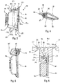
figure 3 est une vue en perspective d'un module de pilotage électronique selon un mode de réalisation de l'invention ; - la
figure 4 est une vue en perspective d'un support selon un mode de réalisation, le module de pilotage de lafigure 3 étant configuré pour être reçu dans le support de lafigure 4 ; - les
figures 5 et 6 illustrent un ensemble formé du module de pilotage de lafigure 3 et du support de lafigure 4 , dans une configuration assemblée, vu en perspective (figure 5 ) ou en coupe (figure 6 ) ; - les
figures 7 et 8 illustrent l'ensemble desfigures 5 et 6 implanté dans un boîtier du dispositif lumineux, dans une position de fonctionnement, vue depuis l'intérieur du boîtier (figure 7 ) et depuis l'extérieur du boîtier (figure 8 ) ; - la
figure 9 illustre une étape successive d'un procédé de remplacement d'un module de pilotage électronique défectueux, lors de laquelle on retire l'ensemble desfigures 5 et6 de l'intérieur du boîtier, par découpage d'une partie de la paroi illustrée sur lafigure 8 .
- the
figure 1 illustrates a light device, including lighting and / or signaling of a motor vehicle, seen from above; - the
figure 2 is a view of the housing forming part of the device of thefigure 1 , seen from the inside in perspective; - the
figure 3 is a perspective view of an electronic control module according to one embodiment of the invention; - the
figure 4 is a perspective view of a support according to one embodiment, the control module of thefigure 3 being configured to be received in the support of thefigure 4 ; - the
Figures 5 and 6 illustrate a set of training module of thefigure 3 and the support of thefigure 4 , in an assembled configuration, seen in perspective (figure 5 ) or in section (figure 6 ); - the
Figures 7 and 8 illustrate allFigures 5 and 6 implanted in a housing of the light device, in an operating position, seen from inside the housing (figure 7 ) and from outside the case (figure 8 ); - the
figure 9 illustrates a successive step of a method of replacing a faulty electronic control module, during which all thefigures 5 and6 of the interior of the housing, by cutting a portion of the wall illustrated on thefigure 8 .
Le dispositif 100 de la
Tel que cela a pu être précisé précédemment, le module de pilotage électronique 13 détermine en fonction de données qu'il reçoit la valeur de la tension d'alimentation de la source de lumière 12. Le module de pilotage électronique 13 comporte au moins une carte support 15 de composants électroniques, sensiblement plane, à partir de laquelle se déploient un faisceau de câbles électriques 14 (visibles sur les
La carte 15 comprend des composants électroniques non illustrés situés sur une première face 17 de la carte, sur laquelle est rigidement fixé le couvercle 16. Le couvercle 16 présente une portion centrale 16a bombée recouvrant les composants électroniques de la carte et délimitée par une paroi latérale périphérique 16b, ainsi qu'un contour 18 sensiblement plan plaqué contre la carte prolongeant cette paroi latérale périphérique.The
Pour la mise en position du couvercle 16 sur la première face 17 de la carte 15, on peut prévoir des moyens d'indexage 19 par coopération de pions 19a portés par la carte 15 avec des orifices formés dans des doigts 19b portés par le couvercle. La fixation du couvercle sur la carte est ensuite réalisée par tous moyen, par exemple par collage.For the positioning of the
Le module de pilotage électronique 13 présente, à un premier bord d'extrémité 20, une portion de connexion 21 configurée pour coopérer avec un support 30 tel qu'il va être décrit ci-après, et à un deuxième bord d'extrémité opposé 22, une portion de guidage 23 configurée pour coopérer avec une tranchée aménagée dans une paroi interne au boîtier telle qu'elle sera décrite ci-après.The
La portion de connexion 21 comprend au moins une nervure 24 rectiligne, s'étendant perpendiculairement, ou sensiblement perpendiculairement, au plan défini par la carte 15 support des composants électroniques. Dans l'exemple illustré, la nervure 24 s'étend sur toute la largeur du module de pilotage 13, c'est-à-dire sur toute la dimension du premier bord d'extrémité 20, d'un coin à un autre de la carte 15.The connecting
Il est notable, dans l'exemple illustré sur les 3 et 6, que la portion de connexion est formée par une nervure rectiligne 24 prolongeant sensiblement perpendiculairement le contour 18 du couvercle 16. Le couvercle peut notamment être réalisé en acier galvanisé (et par exemple un acier galvanisé du type DX 54 + Z 100). Le matériau choisi permet de réaliser la nervure par pliure depuis un bord du couvercle 16, en étant suffisamment rigide pour tenir lorsqu'on extrait le support. Notamment, la nervure rectiligne 24 peut prolonger un bord du couvercle par une pliure, de sorte que la portion de connexion 21 présente une forme en L, avec le contour 18 du couvercle et la nervure rectiligne 24. Cette nervure a pour effet d'accrocher le couvercle et par conséquent l'ensemble du module de pilotage électronique 13 au support 30. On comprendra que la nervure rectiligne pourrait être agencée à distance constante du premier bord du module de pilotage électronique, la forme profilée de la portion de connexion étant alors différente de la forme en L précédemment décrite et illustrée à titre d'exemple sur les figures. Dans chacun de ces cas, on pourra noter que la nervure rectiligne 24 s'étend à distance de la face latérale périphérique 16b du couvercle 16, séparée par une portion de dégagement 25 plane formée par le contour 18.It is notable, in the example illustrated on the 3 and 6, that the connecting portion is formed by a
Tel que cela est notamment visible sur les
Tel que cela a été précisé, le module de pilotage électronique est configuré pour coopérer avec un logement 29 aménagé dans un support 30, illustré seul à la
La glissière 32 comprend une rainure 34, agencée sur la face interne de l'une des deux parois, en étant sensiblement perpendiculaire à la direction générale du passage défini entre les deux parois de la glissière. La rainure 34 s'étend sensiblement sur toute la longueur du support 30, et elle débouche sur au moins un premier côté 35 de ce support, de sorte que la nervure rectiligne 24 du module de pilotage électronique puisse être insérée dans le logement 29 par coulissement dans la rainure 34 depuis ce premier côté du support. Dans le mode de réalisation illustré, la rainure ne débouche que sur un côté du support et le fond de la rainure dans le support définit une butée à l'insertion du module 13 dans le support selon une direction d'insertion sensiblement parallèle à la direction d'allongement de la rainure.The
Lorsque le module 13 est insérée dans le support, la position du module est maintenue par l'utilisation d'une vis de serrage 36 vissée dans un alésage 36a (visible sur la
Dans la position assemblée du module 13 dans le support 30, illustrée notamment sur la
Ainsi, le module 13 ne peut être séparé du support 30 lorsqu'on exerce une force F (visible sur les
On comprend que tout type de logement apte à accueillir et à maintenir en position la nervure 24 du module est susceptible de convenir, à partir du moment où une sollicitation par une force F telle que précitée ne permet pas de séparer le support 30 du module 13.It is understood that any type of housing adapted to receive and hold in position the
Selon l'invention, la présence de cette nervure rectiligne dans la rainure du support permet la manipulation simultanée du support et du module de pilotage électronique. Ceci est notamment avantageux lorsque l'on souhaite réaliser une extraction d'un module défectueux hors du boîtier d'un dispositif lumineux, tel que cela va être décrit par la suite.According to the invention, the presence of this rectilinear rib in the groove of the support allows the simultaneous manipulation of the support and the electronic control module. This is particularly advantageous when it is desired to perform an extraction of a defective module out of the housing of a light device, as will be described later.
Tel qu'illustré sur la
En se référant à la
Dans l'exemple illustré, la paroi 2 présente autour de cette zone de prédécoupe 3 un bossage 37 formant saillie de la face externe de la paroi 2 du boîtier. A l'intérieur de ce bossage, la paroi présente une épaisseur moindre que dans les autres zones, formant ainsi le capot 31. Tel qu'illustré, la zone de fragilité peut être accentuée par des encoches 38 réalisées de façon continue sur tout le pourtour du capot ou ponctuellement, de sorte que l'on facilite ainsi la prédécoupe du capot 31. Il sera compris que des encoches pourraient également être réalisées sur la face interne de la paroi du boîtier.In the example shown, the
Le bossage périphérique 37 est réalisé sur la paroi de sorte que la projection sur la paroi 2 de chacun des éléments du module de pilotage 13 et du support 30 se trouve à l'intérieur de ce bossage. La zone de prédécoupe est de la sorte au droit du module de pilotage électronique. Ainsi, on s'assure, tel que cela sera décrit après, que lorsque la paroi est découpée au niveau de ce bossage périphérique, l'ensemble formé par le module et le support peut être extrait du boîtier par l'ouverture formée par la découpe de la paroi au niveau du bossage périphérique.The
Tel que cela est visible sur la
Dans le mode de réalisation illustré, le module de pilotage électronique 13 est disposé dans le boîtier entre le logement 29 formé dans le support 30, solidaire d'une des parois 2 délimitant le pourtour extérieur du boîtier, et un logement additionnel 39 formé dans une paroi interne 40 munie d'une tranchée 41.In the illustrated embodiment, the
La tranchée 41 s'étend parallèlement à la rainure 34 réalisée dans le support 30. Elle débouche sur au moins le premier côté 42 de la paroi interne et elle est ouverte en direction du support 30, de sorte que les ouvertures de la tranchée 41 et de la glissière 32 sont en regard l'une de l'autre en l'absence du module. En d'autres termes, la tranchée est définie par deux parois parallèle et une paroi de fond qui s'étend sensiblement parallèlement à la rainure 34. La tranchée est dimensionnée pour que la portion de guidage 23, agencée au deuxième bord d'extrémité 22 du module de pilotage, puisse y être logée, au moins au niveau du deuxième élément en saillie 28.The
Lorsque le support 30 est formé dans la paroi 2 supérieure du boîtier et que la paroi interne 40 s'étend verticalement sous ce support, le module de pilotage électronique repose contre la paroi de fond de la tranchée et la nervure rectiligne est dans la position illustrée sur la
La
Le boitier 1 du dispositif d'éclairage et/ou de signalisation est ici un boîtier plastique, injecté en une seule étape, avec une zone de fixation du module de pilotage électronique comportant le support et sa rainure, et la paroi interne en regard l'une de l'autre.The housing 1 of the lighting and / or signaling device is here a plastic housing, injected in a single step, with a fixing zone of the electronic control module comprising the support and its groove, and the inner wall facing the one of the other.
Avant la première utilisation du boîtier, on insère une carte support de composants électroniques et le couvercle associé dans la glissière 32 du support 30, et le cas échéant dans la tranchée 41. Les éléments en saillie de la carte pénètrent dans le logement 29 et le logement additionnel 39 par le premier côté 35 du support et par le premier côté 42 de la paroi interne. Simultanément, la nervure rectiligne 24 s'insère dans la rainure 34 du support. L'opérateur pousse le module de pilotage pour le faire coulisser à l'intérieur de la glissière 32 et de la paroi interne 40 jusqu'à ce que la nervure rectiligne entre en contact avec le fond de la rainure 34.Before the first use of the housing, an electronic component support card and the associated lid are inserted into the
Dans cette position, le dernier mouvement possible, à savoir la translation en sens inverse du sens d'insertion, est bloqué par le vissage de la vis de serrage 36 dans l'alésage 36a. Ainsi, le module de pilotage 13 est rigidement attaché au support 30, dans une position nominale.In this position, the last possible movement, namely the translation in the opposite direction of the direction of insertion, is blocked by the screwing of the clamping
L'opérateur peut alors assembler dans le boîtier le reste des composants, et notamment les composants optiques, du dispositif lumineux.The operator can then assemble in the housing the rest of the components, and in particular the optical components, of the light device.
On va maintenant décrire un procédé de démontage dont le but est d'extraire le module de pilotage, a fortiori la carte de pilotage 15, du boîtier 1, pour procéder au remplacement d'un module de pilotage défectueux.We will now describe a disassembly process whose purpose is to extract the control module, a fortiori the
Lorsque l'on souhaite changer la carte de pilotage, ou la réparer, on découpe la paroi 2 du boîtier porteuse du support 30, au niveau du bossage périphérique 37, et ce depuis l'extérieur du boîtier. Le fait d'avoir prévu une prédécoupe au niveau de ce bossage périphérique, c'est-à-dire une zone de fragilité et par exemple de moindre épaisseur, permet à l'opérateur de découper la zone adéquate avec un outillage simple, par exemple un simple couteau à lame rétractable ou « Cutter », sans perdre de précision et d'efficacité.When it is desired to change the control board, or repair, cut the
L'opérateur tire alors sur la portion de paroi découpée, correspondant au capot 31 de du support 30, et il entraîne avec le capot l'intégralité du support et le module de pilotage rendu solidaire de cette translation par l'emprisonnement de la nervure rectiligne du module dans la rainure du support. Avant de retirer complètement du boîtier l'ensemble formé par le support et le module, via l'ouverture dans la paroi ainsi découpée, l'opérateur déconnecte les câbles 14 du module défectueux.The operator then pulls on the portion of wall cut, corresponding to the
Lorsque l'opérateur soulève le support 30, la nervure 24 maintenant le module 13 dans le support 30 permet l'entraînement du module 13 avec le support. On retrouve alors l'agencement illustré à la
On comprend à ce stade l'intérêt d'avoir une nervure rectiligne formée sur le module et configurée pour coopérer avec la rainure du support, à savoir la possibilité de retirer facilement le module du boîtier, par l'extérieur, sans nécessité de réaliser des vissages et des dévissages à l'intérieur du boîtier. L'extraction du module défectueux est rapide, simple, et n'engendre pas de risques de dommages pour le dispositif. L'extraction du module est d'autant plus simple et rapide qu'une prédécoupe est réalisée sur une paroi du boîtier. La prédécoupe peut par exemple prendre la forme de lignes de fragilité réalisées volontairement au niveau des contours du boîtier, ou encore de découpes discontinues.It is understood at this stage the advantage of having a rectilinear rib formed on the module and configured to cooperate with the groove of the support, namely the possibility of easily removing the module from the housing, from the outside, without the need to achieve screwing and unscrewing inside the case. The extraction of the defective module is fast, simple, and does not cause any risk of damage to the device. The extraction of the module is all the easier and faster than a precut is performed on a wall of the housing. Pre-cut can for example take the form of fragile lines made voluntarily at the contours of the housing, or discontinuous cutouts.
Une fois le module défectueux retiré, l'opérateur dispose un nouveau module de pilotage dans le boîtier en l'insérant par le passage préalablement formé dans la paroi 2, c'est-à-dire par l'ouverture formé à l'intérieur du bossage périphérique. Il convient de noter que ce nouveau module de pilotage présente avantageusement un ensemble, formé d'une carte, de composants électroniques neufs et d'un couvercle, similaire à celui qui a été précédemment extrait du boîtier, alors que le support diffère du support précédemment retiré, en ce que le capot est plus grand. De la sorte, lorsque le nouveau module de pilotage électronique est déposé, le capot 31 vient reposer contre le bossage périphérique. On peut prévoir un joint d'étanchéité entre le capot et le bossage périphérique pour assurer l'étanchéité du boîtier. Par ailleurs, le nouveau capot comporte des alésages permettant le passage de vis de fixation, ici non représentées, dimensionnées pour coopérer avec les fûts de vissage 37b afin de bloquer en position le nouveau module de pilotage électronique.Once the faulty module removed, the operator has a new control module in the housing by inserting it through the passage previously formed in the
On comprend dès lors que le positionnement du nouveau module de pilotage électronique peut s'effectuer aussi bien par butée du capot sur le bossage périphérique, que par butée du capot sur les fûts de vissage, ou par butée du deuxième élément en saillie 28 du nouveau module de pilotage électronique dans la tranchée de la paroi interne.It is therefore understood that the positioning of the new electronic control module can be performed both by abutment of the cover on the peripheral boss, that by abutment of the cap on the screw drums, or by abutment of the second projecting
La mise en place du nouveau module a ainsi été réalisée avec des opérations de vissage faites à l'extérieur du boîtier, de sorte que l'on évite les risques de chute de vis ou de détérioration de l'intérieur du produit via un tournevis par exemple. Seule une opération de raccordement électrique est nécessaire à l'intérieur du boîtier, c'est-à-dire une opération sans outillage.The introduction of the new module has been achieved with screwing operations made outside the housing, so that it avoids the risk of falling screws or deterioration of the interior of the product via a screwdriver by example. Only an electrical connection operation is necessary inside the housing, that is to say an operation without tools.
Telle qu'elle vient d'être décrite, l'invention permet de simplement remplacer un module de pilotage électronique défectueux sans avoir à risquer la détérioration de composants optiques et/ou électroniques présents par ailleurs dans le boîtier du dispositif lumineux dans lequel est appliquée l'invention.As just described, the invention makes it possible to simply replace a defective electronic control module without having to risk the deterioration of optical and / or electronic components present elsewhere in the housing of the light device in which the light is applied. 'invention.
Claims (20)
le procédé étant caractérisé en ce qu'il comprend une étape de déconnexion électrique de la ou des sources de lumière avec le module de pilotage électronique à remplacer, une étape de découpe partielle de la paroi du boîtier autour du logement, depuis l'extérieur du boîtier, une étape d'extraction du support (30) par rapport au dispositif (100), le support emportant le module (13) par coopération de la nervure (24) du module et de la rainure (34) du support, une étape de positionnement d'un nouveau module de pilotage électronique équipé d'un support comprenant un capot de fermeture s'adaptant à l'ouverture, une étape de raccordement électrique et une étape de fixation d'un capot (31) de fermeture du nouveau module de pilotage électronique sur la paroi (2) du boîtier (1) depuis l'extérieur du boîtier.A method of replacing an electronic control module (13) arranged inside a light device (100) by being electrically connected to one or more light sources (12), the electronic control module (13) being housed in a nominal position in a support (30) integral with a wall (2) of a housing (1) of the light device, with at least one rib (24) of the control module extending in a groove (34) ) of the support (30) substantially parallel to said wall (2),
the method being characterized in that it comprises a step of electrically disconnecting the light source or sources with the electronic control module to be replaced, a step of partially cutting the wall of the housing around the housing, from outside the housing, a step of extraction of the support (30) relative to the device (100), the support carrying the module (13) by cooperation of the rib (24) of the module and the groove (34) of the support, a step positioning a new control module electronic device comprising a support comprising a closing cap adapted to the opening, an electrical connection step and a step of fixing a cover (31) for closing the new electronic control module on the wall (2) housing (1) from outside the housing.
Applications Claiming Priority (1)
| Application Number | Priority Date | Filing Date | Title |
|---|---|---|---|
| FR1653637A FR3050605B1 (en) | 2016-04-25 | 2016-04-25 | ELECTRONIC DRIVER MODULE OF A VEHICLE LIGHTING AND / OR SIGNALING DEVICE, AND METHOD OF REPLACING SUCH A MODULE |
Publications (2)
| Publication Number | Publication Date |
|---|---|
| EP3240384A1 true EP3240384A1 (en) | 2017-11-01 |
| EP3240384B1 EP3240384B1 (en) | 2021-04-07 |
Family
ID=56119643
Family Applications (1)
| Application Number | Title | Priority Date | Filing Date |
|---|---|---|---|
| EP17166715.7A Active EP3240384B1 (en) | 2016-04-25 | 2017-04-14 | Module for electronic control of a lighting and/or signalling device of a vehicle, and method for replacing such a module |
Country Status (4)
| Country | Link |
|---|---|
| US (1) | US10538197B2 (en) |
| EP (1) | EP3240384B1 (en) |
| CN (1) | CN107305001B (en) |
| FR (1) | FR3050605B1 (en) |
Cited By (3)
| Publication number | Priority date | Publication date | Assignee | Title |
|---|---|---|---|---|
| CN108980671A (en) * | 2018-02-20 | 2018-12-11 | 宁波万汇休闲用品有限公司 | Sound equipment lamp |
| FR3083179A1 (en) * | 2018-06-29 | 2020-01-03 | Valeo Vision | LIGHT DEVICE FOR A MOTOR VEHICLE |
| FR3100868A1 (en) * | 2019-09-12 | 2021-03-19 | Psa Automobiles Sa | Blanking element for a motor vehicle headlight |
Families Citing this family (4)
| Publication number | Priority date | Publication date | Assignee | Title |
|---|---|---|---|---|
| US11639039B1 (en) | 2016-02-04 | 2023-05-02 | Maurice Paperi | Matching pieces and kits for repairing broken structures and related methods |
| US11148578B2 (en) | 2018-03-25 | 2021-10-19 | Maurice Paperi | Universal mounting tabs and kits for automotive components |
| DE102019118805A1 (en) | 2019-07-11 | 2021-01-14 | Endress+Hauser Flowtec Ag | Housing module and field device |
| KR20230108822A (en) * | 2022-01-12 | 2023-07-19 | 현대모비스 주식회사 | Vehicle lamp |
Citations (3)
| Publication number | Priority date | Publication date | Assignee | Title |
|---|---|---|---|---|
| EP2362720A1 (en) * | 2010-02-18 | 2011-08-31 | Airbus Operations | Electronic module and electronique assembly comprising the same |
| EP2479062A1 (en) * | 2011-01-21 | 2012-07-25 | Valeo Vision | Electrical equipment for an automobile, in particular a lighting or signalling device. |
| US20150176795A1 (en) * | 2013-12-20 | 2015-06-25 | Koito Manufacturing Co., Ltd. | Vehicle headlamp |
Family Cites Families (7)
| Publication number | Priority date | Publication date | Assignee | Title |
|---|---|---|---|---|
| US7679924B2 (en) * | 2005-10-17 | 2010-03-16 | Alcatel Lucent | Configurable chassis guidance system and method |
| JP5146278B2 (en) * | 2008-11-18 | 2013-02-20 | 富士通株式会社 | Printed circuit board and printed circuit board mounting structure |
| JP5223121B2 (en) * | 2009-12-11 | 2013-06-26 | 豊田合成株式会社 | Light source unit for vehicles |
| FR2994788B1 (en) * | 2012-08-27 | 2016-09-16 | Valeo Vision | Lighting and / or signaling device for a vehicle comprising a lighting module with a control device removably maintained |
| US20160010838A1 (en) * | 2014-07-14 | 2016-01-14 | RSI Development LLC | Lighting system |
| FR3036162B1 (en) * | 2015-05-13 | 2017-06-16 | Valeo Vision | LIGHTING MODULE BIFUNCTION CODE - ROAD FOR MOTOR VEHICLE |
| FR3037381B1 (en) * | 2015-06-11 | 2021-02-19 | Valeo Vision | DEVICE FOR POSITIONING A LIGHT SUPPORT OF A LIGHT-LUMINESCENT DIODE ON A SUPPORT ELEMENT AND LIGHT MODULE FOR A LIGHTING AND / OR SIGNALING DEVICE CONTAINING SUCH A DEVICE |
-
2016
- 2016-04-25 FR FR1653637A patent/FR3050605B1/en not_active Expired - Fee Related
-
2017
- 2017-04-14 EP EP17166715.7A patent/EP3240384B1/en active Active
- 2017-04-24 CN CN201710270744.9A patent/CN107305001B/en active Active
- 2017-04-25 US US15/496,608 patent/US10538197B2/en active Active
Patent Citations (3)
| Publication number | Priority date | Publication date | Assignee | Title |
|---|---|---|---|---|
| EP2362720A1 (en) * | 2010-02-18 | 2011-08-31 | Airbus Operations | Electronic module and electronique assembly comprising the same |
| EP2479062A1 (en) * | 2011-01-21 | 2012-07-25 | Valeo Vision | Electrical equipment for an automobile, in particular a lighting or signalling device. |
| US20150176795A1 (en) * | 2013-12-20 | 2015-06-25 | Koito Manufacturing Co., Ltd. | Vehicle headlamp |
Cited By (4)
| Publication number | Priority date | Publication date | Assignee | Title |
|---|---|---|---|---|
| CN108980671A (en) * | 2018-02-20 | 2018-12-11 | 宁波万汇休闲用品有限公司 | Sound equipment lamp |
| CN108980671B (en) * | 2018-02-20 | 2021-01-29 | 宁波万汇休闲用品有限公司 | Sound lamp |
| FR3083179A1 (en) * | 2018-06-29 | 2020-01-03 | Valeo Vision | LIGHT DEVICE FOR A MOTOR VEHICLE |
| FR3100868A1 (en) * | 2019-09-12 | 2021-03-19 | Psa Automobiles Sa | Blanking element for a motor vehicle headlight |
Also Published As
| Publication number | Publication date |
|---|---|
| EP3240384B1 (en) | 2021-04-07 |
| CN107305001B (en) | 2021-07-23 |
| FR3050605B1 (en) | 2018-05-18 |
| US20170305334A1 (en) | 2017-10-26 |
| US10538197B2 (en) | 2020-01-21 |
| FR3050605A1 (en) | 2017-10-27 |
| CN107305001A (en) | 2017-10-31 |
Similar Documents
| Publication | Publication Date | Title |
|---|---|---|
| EP3240384B1 (en) | Module for electronic control of a lighting and/or signalling device of a vehicle, and method for replacing such a module | |
| EP2775197B1 (en) | Lighting and/or signalling device for a motor vehicle comprising a light guide | |
| FR2773838A1 (en) | PROVISIONAL CLOSING DEVICE OF AN ELEMENT OPENING ON A FIXED ELEMENT OF A BODY OF A MOTOR VEHICLE | |
| EP1094581A1 (en) | Passage accessory for channel | |
| EP3045357A1 (en) | Cap for a windscreen wiper for covering an end portion of a wiper arm | |
| EP1138963B1 (en) | Holding device for a cable control conduit | |
| EP1106774B1 (en) | Device for securing a drive, and actuating mechanism of a closure or solar protection unit with such a device | |
| EP2736774B1 (en) | Supporting device and assembly, and method for mounting a pair of wiper blades | |
| EP2479062B1 (en) | Electrical equipment for an automobile, in particular a lighting or signalling device | |
| EP3321129B1 (en) | Device for screwless mounting of a projector control housing on said projector | |
| FR3083179A1 (en) | LIGHT DEVICE FOR A MOTOR VEHICLE | |
| EP1139537B1 (en) | Electrical apparatus box to be placed alongside a cable duct | |
| EP2006155A1 (en) | Device for tamper-proof attachment of a part in a cut-out made in a structure | |
| EP0923176B1 (en) | Jaw fastening accessory for flush mounted box and associated flush mounted box | |
| EP3422082B1 (en) | Image projection unit suitable for receiving a partially transparent slide, associated partially transparent slide and head-up display | |
| EP3040238B1 (en) | Light device for a motor vehicle | |
| EP3409567A1 (en) | Support device for a dashboard of a motor vehicle | |
| FR2972401A1 (en) | Electrical equipment e.g. daytime running lamp, for motor vehicle, has housing including wall with rib bordering contour of frangible portion by being shaped for allowing orientation and guiding of cutting tool along contour | |
| WO2023012090A1 (en) | Light module intended for being attached to a light device of a motor vehicle | |
| FR2704381A1 (en) | Tracking device for electrical conductor. | |
| EP3881003B1 (en) | Headlamp unit for a motor vehicle with a protective shield attached to a frame | |
| EP1470942B1 (en) | Arrangement to fasten a support of a sun curtain | |
| WO2020025294A1 (en) | Vehicle comprising a lighting component with simplified attachment | |
| WO2023247849A1 (en) | Device for mounting a motor vehicle optical unit electrical connection strip on a supporting structure | |
| FR2765660A1 (en) | Quick release protective cage for emergency lighting |
Legal Events
| Date | Code | Title | Description |
|---|---|---|---|
| PUAI | Public reference made under article 153(3) epc to a published international application that has entered the european phase |
Free format text: ORIGINAL CODE: 0009012 |
|
| STAA | Information on the status of an ep patent application or granted ep patent |
Free format text: STATUS: THE APPLICATION HAS BEEN PUBLISHED |
|
| AK | Designated contracting states |
Kind code of ref document: A1 Designated state(s): AL AT BE BG CH CY CZ DE DK EE ES FI FR GB GR HR HU IE IS IT LI LT LU LV MC MK MT NL NO PL PT RO RS SE SI SK SM TR |
|
| AX | Request for extension of the european patent |
Extension state: BA ME |
|
| STAA | Information on the status of an ep patent application or granted ep patent |
Free format text: STATUS: REQUEST FOR EXAMINATION WAS MADE |
|
| 17P | Request for examination filed |
Effective date: 20180425 |
|
| RBV | Designated contracting states (corrected) |
Designated state(s): AL AT BE BG CH CY CZ DE DK EE ES FI FR GB GR HR HU IE IS IT LI LT LU LV MC MK MT NL NO PL PT RO RS SE SI SK SM TR |
|
| REG | Reference to a national code |
Ref country code: DE Ref legal event code: R079 Ref document number: 602017036014 Country of ref document: DE Free format text: PREVIOUS MAIN CLASS: H05K0007140000 Ipc: H05K0005000000 |
|
| GRAP | Despatch of communication of intention to grant a patent |
Free format text: ORIGINAL CODE: EPIDOSNIGR1 |
|
| STAA | Information on the status of an ep patent application or granted ep patent |
Free format text: STATUS: GRANT OF PATENT IS INTENDED |
|
| RIC1 | Information provided on ipc code assigned before grant |
Ipc: H05K 5/00 20060101AFI20201102BHEP |
|
| INTG | Intention to grant announced |
Effective date: 20201120 |
|
| GRAS | Grant fee paid |
Free format text: ORIGINAL CODE: EPIDOSNIGR3 |
|
| GRAA | (expected) grant |
Free format text: ORIGINAL CODE: 0009210 |
|
| STAA | Information on the status of an ep patent application or granted ep patent |
Free format text: STATUS: THE PATENT HAS BEEN GRANTED |
|
| AK | Designated contracting states |
Kind code of ref document: B1 Designated state(s): AL AT BE BG CH CY CZ DE DK EE ES FI FR GB GR HR HU IE IS IT LI LT LU LV MC MK MT NL NO PL PT RO RS SE SI SK SM TR |
|
| REG | Reference to a national code |
Ref country code: GB Ref legal event code: FG4D Free format text: NOT ENGLISH |
|
| REG | Reference to a national code |
Ref country code: AT Ref legal event code: REF Ref document number: 1381397 Country of ref document: AT Kind code of ref document: T Effective date: 20210415 Ref country code: CH Ref legal event code: EP |
|
| REG | Reference to a national code |
Ref country code: DE Ref legal event code: R096 Ref document number: 602017036014 Country of ref document: DE |
|
| REG | Reference to a national code |
Ref country code: IE Ref legal event code: FG4D Free format text: LANGUAGE OF EP DOCUMENT: FRENCH |
|
| REG | Reference to a national code |
Ref country code: LT Ref legal event code: MG9D |
|
| REG | Reference to a national code |
Ref country code: NL Ref legal event code: MP Effective date: 20210407 Ref country code: AT Ref legal event code: MK05 Ref document number: 1381397 Country of ref document: AT Kind code of ref document: T Effective date: 20210407 |
|
| PG25 | Lapsed in a contracting state [announced via postgrant information from national office to epo] |
Ref country code: LT Free format text: LAPSE BECAUSE OF FAILURE TO SUBMIT A TRANSLATION OF THE DESCRIPTION OR TO PAY THE FEE WITHIN THE PRESCRIBED TIME-LIMIT Effective date: 20210407 Ref country code: FI Free format text: LAPSE BECAUSE OF FAILURE TO SUBMIT A TRANSLATION OF THE DESCRIPTION OR TO PAY THE FEE WITHIN THE PRESCRIBED TIME-LIMIT Effective date: 20210407 Ref country code: HR Free format text: LAPSE BECAUSE OF FAILURE TO SUBMIT A TRANSLATION OF THE DESCRIPTION OR TO PAY THE FEE WITHIN THE PRESCRIBED TIME-LIMIT Effective date: 20210407 Ref country code: BG Free format text: LAPSE BECAUSE OF FAILURE TO SUBMIT A TRANSLATION OF THE DESCRIPTION OR TO PAY THE FEE WITHIN THE PRESCRIBED TIME-LIMIT Effective date: 20210707 Ref country code: AT Free format text: LAPSE BECAUSE OF FAILURE TO SUBMIT A TRANSLATION OF THE DESCRIPTION OR TO PAY THE FEE WITHIN THE PRESCRIBED TIME-LIMIT Effective date: 20210407 Ref country code: NL Free format text: LAPSE BECAUSE OF FAILURE TO SUBMIT A TRANSLATION OF THE DESCRIPTION OR TO PAY THE FEE WITHIN THE PRESCRIBED TIME-LIMIT Effective date: 20210407 |
|
| PG25 | Lapsed in a contracting state [announced via postgrant information from national office to epo] |
Ref country code: LV Free format text: LAPSE BECAUSE OF FAILURE TO SUBMIT A TRANSLATION OF THE DESCRIPTION OR TO PAY THE FEE WITHIN THE PRESCRIBED TIME-LIMIT Effective date: 20210407 Ref country code: GR Free format text: LAPSE BECAUSE OF FAILURE TO SUBMIT A TRANSLATION OF THE DESCRIPTION OR TO PAY THE FEE WITHIN THE PRESCRIBED TIME-LIMIT Effective date: 20210708 Ref country code: IS Free format text: LAPSE BECAUSE OF FAILURE TO SUBMIT A TRANSLATION OF THE DESCRIPTION OR TO PAY THE FEE WITHIN THE PRESCRIBED TIME-LIMIT Effective date: 20210807 Ref country code: SE Free format text: LAPSE BECAUSE OF FAILURE TO SUBMIT A TRANSLATION OF THE DESCRIPTION OR TO PAY THE FEE WITHIN THE PRESCRIBED TIME-LIMIT Effective date: 20210407 Ref country code: RS Free format text: LAPSE BECAUSE OF FAILURE TO SUBMIT A TRANSLATION OF THE DESCRIPTION OR TO PAY THE FEE WITHIN THE PRESCRIBED TIME-LIMIT Effective date: 20210407 Ref country code: NO Free format text: LAPSE BECAUSE OF FAILURE TO SUBMIT A TRANSLATION OF THE DESCRIPTION OR TO PAY THE FEE WITHIN THE PRESCRIBED TIME-LIMIT Effective date: 20210707 Ref country code: PT Free format text: LAPSE BECAUSE OF FAILURE TO SUBMIT A TRANSLATION OF THE DESCRIPTION OR TO PAY THE FEE WITHIN THE PRESCRIBED TIME-LIMIT Effective date: 20210809 Ref country code: PL Free format text: LAPSE BECAUSE OF FAILURE TO SUBMIT A TRANSLATION OF THE DESCRIPTION OR TO PAY THE FEE WITHIN THE PRESCRIBED TIME-LIMIT Effective date: 20210407 |
|
| PG25 | Lapsed in a contracting state [announced via postgrant information from national office to epo] |
Ref country code: LU Free format text: LAPSE BECAUSE OF NON-PAYMENT OF DUE FEES Effective date: 20210414 |
|
| REG | Reference to a national code |
Ref country code: DE Ref legal event code: R097 Ref document number: 602017036014 Country of ref document: DE |
|
| REG | Reference to a national code |
Ref country code: BE Ref legal event code: MM Effective date: 20210430 |
|
| PG25 | Lapsed in a contracting state [announced via postgrant information from national office to epo] |
Ref country code: CZ Free format text: LAPSE BECAUSE OF FAILURE TO SUBMIT A TRANSLATION OF THE DESCRIPTION OR TO PAY THE FEE WITHIN THE PRESCRIBED TIME-LIMIT Effective date: 20210407 Ref country code: DK Free format text: LAPSE BECAUSE OF FAILURE TO SUBMIT A TRANSLATION OF THE DESCRIPTION OR TO PAY THE FEE WITHIN THE PRESCRIBED TIME-LIMIT Effective date: 20210407 Ref country code: EE Free format text: LAPSE BECAUSE OF FAILURE TO SUBMIT A TRANSLATION OF THE DESCRIPTION OR TO PAY THE FEE WITHIN THE PRESCRIBED TIME-LIMIT Effective date: 20210407 Ref country code: LI Free format text: LAPSE BECAUSE OF NON-PAYMENT OF DUE FEES Effective date: 20210430 Ref country code: MC Free format text: LAPSE BECAUSE OF FAILURE TO SUBMIT A TRANSLATION OF THE DESCRIPTION OR TO PAY THE FEE WITHIN THE PRESCRIBED TIME-LIMIT Effective date: 20210407 Ref country code: ES Free format text: LAPSE BECAUSE OF FAILURE TO SUBMIT A TRANSLATION OF THE DESCRIPTION OR TO PAY THE FEE WITHIN THE PRESCRIBED TIME-LIMIT Effective date: 20210406 Ref country code: RO Free format text: LAPSE BECAUSE OF FAILURE TO SUBMIT A TRANSLATION OF THE DESCRIPTION OR TO PAY THE FEE WITHIN THE PRESCRIBED TIME-LIMIT Effective date: 20210407 Ref country code: SM Free format text: LAPSE BECAUSE OF FAILURE TO SUBMIT A TRANSLATION OF THE DESCRIPTION OR TO PAY THE FEE WITHIN THE PRESCRIBED TIME-LIMIT Effective date: 20210407 Ref country code: SK Free format text: LAPSE BECAUSE OF FAILURE TO SUBMIT A TRANSLATION OF THE DESCRIPTION OR TO PAY THE FEE WITHIN THE PRESCRIBED TIME-LIMIT Effective date: 20210407 Ref country code: CH Free format text: LAPSE BECAUSE OF NON-PAYMENT OF DUE FEES Effective date: 20210430 |
|
| PLBE | No opposition filed within time limit |
Free format text: ORIGINAL CODE: 0009261 |
|
| STAA | Information on the status of an ep patent application or granted ep patent |
Free format text: STATUS: NO OPPOSITION FILED WITHIN TIME LIMIT |
|
| 26N | No opposition filed |
Effective date: 20220110 |
|
| GBPC | Gb: european patent ceased through non-payment of renewal fee |
Effective date: 20210707 |
|
| PG25 | Lapsed in a contracting state [announced via postgrant information from national office to epo] |
Ref country code: IE Free format text: LAPSE BECAUSE OF NON-PAYMENT OF DUE FEES Effective date: 20210414 Ref country code: GB Free format text: LAPSE BECAUSE OF NON-PAYMENT OF DUE FEES Effective date: 20210707 |
|
| PG25 | Lapsed in a contracting state [announced via postgrant information from national office to epo] |
Ref country code: IS Free format text: LAPSE BECAUSE OF FAILURE TO SUBMIT A TRANSLATION OF THE DESCRIPTION OR TO PAY THE FEE WITHIN THE PRESCRIBED TIME-LIMIT Effective date: 20210807 Ref country code: AL Free format text: LAPSE BECAUSE OF FAILURE TO SUBMIT A TRANSLATION OF THE DESCRIPTION OR TO PAY THE FEE WITHIN THE PRESCRIBED TIME-LIMIT Effective date: 20210407 |
|
| PG25 | Lapsed in a contracting state [announced via postgrant information from national office to epo] |
Ref country code: IT Free format text: LAPSE BECAUSE OF FAILURE TO SUBMIT A TRANSLATION OF THE DESCRIPTION OR TO PAY THE FEE WITHIN THE PRESCRIBED TIME-LIMIT Effective date: 20210407 Ref country code: BE Free format text: LAPSE BECAUSE OF NON-PAYMENT OF DUE FEES Effective date: 20210430 |
|
| PG25 | Lapsed in a contracting state [announced via postgrant information from national office to epo] |
Ref country code: HU Free format text: LAPSE BECAUSE OF FAILURE TO SUBMIT A TRANSLATION OF THE DESCRIPTION OR TO PAY THE FEE WITHIN THE PRESCRIBED TIME-LIMIT; INVALID AB INITIO Effective date: 20170414 |
|
| PG25 | Lapsed in a contracting state [announced via postgrant information from national office to epo] |
Ref country code: CY Free format text: LAPSE BECAUSE OF FAILURE TO SUBMIT A TRANSLATION OF THE DESCRIPTION OR TO PAY THE FEE WITHIN THE PRESCRIBED TIME-LIMIT Effective date: 20210407 |
|
| P01 | Opt-out of the competence of the unified patent court (upc) registered |
Effective date: 20230528 |
|
| PG25 | Lapsed in a contracting state [announced via postgrant information from national office to epo] |
Ref country code: MK Free format text: LAPSE BECAUSE OF FAILURE TO SUBMIT A TRANSLATION OF THE DESCRIPTION OR TO PAY THE FEE WITHIN THE PRESCRIBED TIME-LIMIT Effective date: 20210407 |
|
| PG25 | Lapsed in a contracting state [announced via postgrant information from national office to epo] |
Ref country code: TR Free format text: LAPSE BECAUSE OF FAILURE TO SUBMIT A TRANSLATION OF THE DESCRIPTION OR TO PAY THE FEE WITHIN THE PRESCRIBED TIME-LIMIT Effective date: 20210407 |
|
| PGFP | Annual fee paid to national office [announced via postgrant information from national office to epo] |
Ref country code: DE Payment date: 20240409 Year of fee payment: 8 |
|
| PGFP | Annual fee paid to national office [announced via postgrant information from national office to epo] |
Ref country code: FR Payment date: 20240423 Year of fee payment: 8 |
|
| PG25 | Lapsed in a contracting state [announced via postgrant information from national office to epo] |
Ref country code: MT Free format text: LAPSE BECAUSE OF FAILURE TO SUBMIT A TRANSLATION OF THE DESCRIPTION OR TO PAY THE FEE WITHIN THE PRESCRIBED TIME-LIMIT Effective date: 20210407 |