EP3240154B1 - Terminalblock, elektrische maschine mit einem solchen terminalblock und fahrzeug mit einer solchen elektrischen maschine - Google Patents
Terminalblock, elektrische maschine mit einem solchen terminalblock und fahrzeug mit einer solchen elektrischen maschine Download PDFInfo
- Publication number
- EP3240154B1 EP3240154B1 EP17168413.7A EP17168413A EP3240154B1 EP 3240154 B1 EP3240154 B1 EP 3240154B1 EP 17168413 A EP17168413 A EP 17168413A EP 3240154 B1 EP3240154 B1 EP 3240154B1
- Authority
- EP
- European Patent Office
- Prior art keywords
- conductive
- terminal block
- electric
- terminal
- insulating
- Prior art date
- Legal status (The legal status is an assumption and is not a legal conclusion. Google has not performed a legal analysis and makes no representation as to the accuracy of the status listed.)
- Active
Links
Images

Classifications
-
- H—ELECTRICITY
- H02—GENERATION; CONVERSION OR DISTRIBUTION OF ELECTRIC POWER
- H02K—DYNAMO-ELECTRIC MACHINES
- H02K5/00—Casings; Enclosures; Supports
- H02K5/04—Casings or enclosures characterised by the shape, form or construction thereof
- H02K5/22—Auxiliary parts of casings not covered by groups H02K5/06-H02K5/20, e.g. shaped to form connection boxes or terminal boxes
- H02K5/225—Terminal boxes or connection arrangements
-
- H—ELECTRICITY
- H01—ELECTRIC ELEMENTS
- H01R—ELECTRICALLY-CONDUCTIVE CONNECTIONS; STRUCTURAL ASSOCIATIONS OF A PLURALITY OF MUTUALLY-INSULATED ELECTRICAL CONNECTING ELEMENTS; COUPLING DEVICES; CURRENT COLLECTORS
- H01R13/00—Details of coupling devices of the kinds covered by groups H01R12/70 or H01R24/00 - H01R33/00
- H01R13/46—Bases; Cases
- H01R13/53—Bases or cases for heavy duty; Bases or cases for high voltage with means for preventing corona or arcing
-
- H—ELECTRICITY
- H01—ELECTRIC ELEMENTS
- H01R—ELECTRICALLY-CONDUCTIVE CONNECTIONS; STRUCTURAL ASSOCIATIONS OF A PLURALITY OF MUTUALLY-INSULATED ELECTRICAL CONNECTING ELEMENTS; COUPLING DEVICES; CURRENT COLLECTORS
- H01R9/00—Structural associations of a plurality of mutually-insulated electrical connecting elements, e.g. terminal strips or terminal blocks; Terminals or binding posts mounted upon a base or in a case; Bases therefor
- H01R9/22—Bases, e.g. strip, block, panel
- H01R9/24—Terminal blocks
-
- H—ELECTRICITY
- H02—GENERATION; CONVERSION OR DISTRIBUTION OF ELECTRIC POWER
- H02K—DYNAMO-ELECTRIC MACHINES
- H02K11/00—Structural association of dynamo-electric machines with electric components or with devices for shielding, monitoring or protection
- H02K11/40—Structural association with grounding devices
Definitions
- the present invention relates to a terminal block, an electric machine, such as an electric traction motor of a vehicle with electric traction, or a generator, comprising such a terminal block, and an electric traction vehicle comprising such an electric motor. .
- the invention relates to the field of electric power supply of electrical machines and the protection of the latter.
- the invention finds particular application in the field of electric traction vehicles, that is to say a vehicle that is towed or propelled by one or more electrical modules, and whose source of electrical energy is not embedded in the vehicle.
- the electrical energy is captured by the vehicle, for example using a conventional system of pantograph and catenary, or by electrical contact with a power rail.
- the electric traction vehicles concerned are for example a metro, a tram or a train.
- the traction motor is formed by a synchronous motor with permanent magnets, provided with a terminal block, sometimes called “terminal box", powered by an inverter or any other power supply means of the engine.
- the inverter is designed to process the electrical energy captured by the vehicle and thus control the engine.
- the vehicle is provided with means for electrically insulating the motor of the inverter, in the event of detection of an electrical fault within the motor. This means comprises for example a contactor, electrically interposed between the inverter and the terminal block of the motor.
- the permanent magnet electric motor even isolated from the inverter by the opening of the contactor, maintains an electromotive force voltage at its terminals when it is driven by the advance of the vehicle, that is to say when the axles of the latter are rotating for example under the effect of the inertia of the vehicle or the drive by the other engines of the vehicle.
- an electric arc is then likely to form, in particular between two terminals of the terminal block, and is maintained as long as the engine is driven by the advancement of the train. Once the insulation between the terminals of the damaged terminal block, it becomes impossible to stop the electric arc established between the terminals as the engine is driven.
- US-A1-2012 / 0133224 discloses a terminal box for a three-phase motor, whose terminals are sealed by insulating partitions to increase the ignition distance between them and reduce the risk of arcing. Nevertheless, this type of terminal boxes is not a priori sufficient for electric motors with permanent magnets, for which a heating of a terminal is likely to break the insulating partitions and thus create a short circuit between two terminals of the terminal box.
- the invention aims to overcome the drawbacks of the aforementioned prior art, by proposing a new terminal block capable of preventing the partial or total destruction of an electrical machine to which it is connected, despite an electrical fault. within the latter.
- the invention relates to a terminal block, for an electric machine, such as an electric traction motor or a generator, the electric machine having at least two phase terminals, the terminal block comprising at least two connection plates and, for each connecting plate, means for fixing one of the phase terminals and a secondary terminal for supplying electrical energy to, and / or receiving electrical energy emitted at, the phase terminal concerned, at least an insulating intermediate partition of the terminal block being interposed between the connection plates.
- this terminal block comprises at least one conductive intermediate core, which is disposed within each insulating intermediate partition and which is configured to be electrically connected to an electric ground of the electrical machine.
- any partial or total destruction of the insulating intermediate partition due to an electrical fault at one of the terminals causes the formation of an electric arc between the conductive intermediate core and the conductive intermediate core. from one of the following faulty elements: one of the connection boards, one of the phase terminals, or one of the secondary terminals. Therefore, the risk of short circuit by arc electrical connection between two phase terminals, between two secondary terminals or between two connection boards, is avoided.
- the short-circuit is thus diverted towards the electric mass of the electric machine via the conductive intermediate core, so that the damage imputed to the electric machine, following the electrical fault, is at least partially avoided and that the Imbalance of phase currents induced by this short circuit to ground can be detected by a control system provided upstream.
- the invention also relates to an electric machine, such as an electric traction motor or a generator, the electric machine having at least two phase terminals and an electrical ground, the electrical machine comprising a terminal block according to the foregoing, each of the phase terminals being fixed to one of the connection boards by the fixing means, and each conductive intermediate core being electrically connected to the electrical ground.
- an electric machine such as an electric traction motor or a generator
- the electric machine having at least two phase terminals and an electrical ground
- the electrical machine comprising a terminal block according to the foregoing, each of the phase terminals being fixed to one of the connection boards by the fixing means, and each conductive intermediate core being electrically connected to the electrical ground.
- the invention also relates to an electric traction vehicle, comprising such an electric machine, the electric machine constituting an electric traction motor of the vehicle, the vehicle comprising a power circuit including an electrical mass to which the electric traction motor is electrically connected.
- the power circuit comprising a power supply device, such as an inverter, with at least two secondary terminals for supplying the phase terminals of the electric traction motor with electrical energy, each secondary terminal being fixed to the one of the connection plates by the fastening means.
- the term “insulator” refers to sufficient electrical insulation for the purposes of the electrical machine for which the terminal block is used, under normal use. In electrical fault case within this electrical machine, the elements qualified with the term “insulator” are likely to no longer be electrically insulating, but instead electrically conductive.
- the term “conductor” refers to, as opposed to “insulator”, to a sufficient electrical conduction for the needs of the electrical machine for which the terminal block is used, under normal conditions of use.
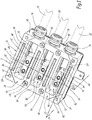
- the terminal block 3, shown in figures 1 and 2 is configured to be integrated with an electric traction motor 5, shown in FIG. figure 5 , of a vehicle with electric traction V, itself represented in this figure by a panel on which is mounted the motor 5 by means of screws not shown.
- the electric motor 5 is preferably a three-phase electric motor with permanent magnets, in particular of the synchronous type.
- the electric motor 5 comprises a three-phase winding, as well as three phase terminals 10, 12 and 14, visible on the figure 1 , which are electrically connected to the three phases and which are in the form of rigid metal contact pieces, in a manner known per se.
- the electric traction vehicle V comprises a power circuit, not illustrated, for supplying the phase terminals 10, 12 and 14 and an electric ground to which the motor 5 is electrically connected.
- the motor 5 comprises a conductive carcass 16 which is connected to the electrical ground of the vehicle V.
- the conductive carcass 16 itself constitutes an electric ground of the motor 5.
- the vehicle power circuit V comprises an inverter including three secondary terminals configured to supply each one of the phase terminals 10, 12 and 14.
- Each secondary terminal comprises a connection cable 18, 20 and 22 for respectively supplying the terminals of phases 10, 12 and 14, the cables 18, 20 and 22 being represented exclusively on the figure 1 in broken lines.
- Each secondary terminal thus supplies electrical energy to one of the phase terminals 10, 12 or 14 via the end of one of the cables 18, 20 or 22 concerned, within the terminal block 3.
- the end of each cable 18, 20 and 22 comprises for example a connecting lug, not shown, respectively with the phase terminals 10, 12 and 14. Thereafter each secondary terminal will have the same reference as the connection cable it comprises.
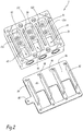
- the terminal block 3 mainly comprises an insulating frame 24, which constitutes a rigid structure.
- the insulating frame 24 is made, at least in majority of its mass, in mat of glass stiffened by a resin.
- the insulating frame 24 forms a solid of parallelepipedal general shape which has an upper face 26, visible at figures 1 to 4 , opposite and parallel to a lower face 28, which is visible on the figures 3 and 4 .
- the insulating frame 24 also comprises a front face 30 connecting the upper 26 and lower 28 faces, and a rear face 32 opposite and parallel to the front face 30.
- the insulating frame 24 finally comprises a left side face 34 and a side face 36 opposite and parallel right, interconnecting the front face 30 and the rear face 32 and the upper face 26 and the lower face 28.
- the grooves 38, 40 and 42 are formed through the insulating frame 24 from the face 26 to the face 28.
- the grooves 38, 40 and 42 are each of generally rectangular section and are arranged parallel to each other , being aligned and regularly spaced between the face 34 and the face 36.
- the through grooves 38 and 40 are separated by an insulating intermediate partition 44 of the frame 24, while the through grooves 40 and 42 are separated by an insulating intermediate partition 46 of the frame 24.
- the frame 24 also comprises two insulating lateral partitions 48 and 50 which are disposed on either side of the through grooves 38, 40 and 42, the insulating lateral partition 48 forming the right side face 36, while the insulating lateral partition 50 forms the left side face 34.
- the partitions 44, 46, 48 and 50 are parallel and extend from the upper face 26 to the lower face 28.
- the partitions 44, 46, 48 and 50 are interconnected by two crosspieces 52 and 54, arranged perpendicular to the partitions 44, 46, 48 and 50, the cross member 52 forming the front face 30 and the cross member 54 forming the rear face 32.
- the insulating frame 24 is provided with three connection plates 56, 58 and 60.
- the plate 56 is provided within the through groove 38, coming integrally with the partitions 48 and 44, close to the bottom face 28.
- the connection plate 58 comes from material with the partitions 44 and 46 near the lower face 28, within the groove 40.
- the plate 60 is provided within the groove 42 and comes from material with the partitions 46 and 50 in the vicinity of the lower face 28.
- the connection plates 56, 58, and 60 only partly block the through grooves 38, 40 and 42 respectively.
- Each connection plate 56, 58 and 60 is thus isolated and separated from its plate. adjacent by one of the intermediate partitions 44 or 46, each intermediate partition 44 and 46 being interposed between two of the plates 56, 58 and 60.
- the insulating side walls 48 and 50 are arranged on either side of the plates of connection ion 56 and 60.
- connection plate 56, 58 and 60 comprises an upper face 62, 64 and 66, which extends parallel to the face 26, between this face 26 and the face 28.
- Each phase terminal 10, 12 and 14 is fixed on one of the upper faces 62, 64 and 66 respectively by means of fastening means, such as screws, nuts, rods threaded threads, or any other equivalent element known as such.
- the fixing means are formed by three pairs of screws 68, 70 and 72, each pair being associated with one of the phase terminals 10, 12 and 14 and one of the plates 56. , 58 and 60.
- the plates 56, 58 and 60 respectively include conductive inserts 57; 59 and 61 in which are implanted pairs of screws 68, 70 and 72.
- the terminal block 3 also comprises three glands 74, 76 and 78 mounted on the crosspiece 52 in a through manner from the face 30 to the inside respectively of the through grooves 38, 40 and 42.
- the cables 18, 20 and 22 are respectively mounted to pass through these glands 74, 76 and 78 and are held tightly by them.
- the end of each cable 18, 20 and 22 extends within one of the through grooves 38, 40 and 42 and is in electrical contact with one of the phase terminals 10, 12 and 14.
- each of these ends is fixed on one of the plates 56, 58 and 60 by means of the fastening means 68, 70 and 72 so as to be in direct contact with the phase terminal 10, 12 or 14 concerned.
- the terminal block 3 also comprises a conductive structure 86 visible in particular at the figure 2 .
- the conductive structure 86 is a metal part intended to be attached to the insulating frame 24.
- the conductive structure 86 is configured to be electrically connected to the electrical ground, for example by means of a cable provided with a terminal, a braid of mass, conductive grease, or any other suitable means.
- the conductive structure 86 optionally includes a tab 88 of electrical recovery for other equipment.
- the conductive structure 86 comprises a conductive base 90 configured to at least partially cover the face 28 of the insulating frame 24. For this, the conductive base 90 forms a metal plate of a shape corresponding to that of the lower face 28.
- the conductive structure 86 also comprises four conductive wings, including two conductive lateral wings 92 and 94 and two conductive intermediate wings 96 and 98 disposed between the conductive lateral wings 92 and 94.
- the conductive wings 92, 94, 96 and 98 form generally rectangular plates protruding from the conductive base 90 extending in planes parallel to each other and regularly spaced.
- the conductive wings 92, 94, 96 and 98 are perpendicular to the conductive base 90 and are preferably fixed permanently on the latter, that is to say definitively, for example using a weld.
- the conductive wings 92, 94, 96 and 98 are made of material with the conductive base 90.
- the conductive wings 92 to 98 are thus electrically interconnected via the conductive base 90 and are therefore also connected to the ground. electric.
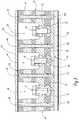
- the insulating partitions 44, 46, 48 and 50 are each provided with a through notch 100, 102, 104 and 106, each of which is formed from the upper face 26 to the lower face 28.
- the conductive flanges 92, 94, 96 and 98 are introduced into the through notches 100 to 106, through the face 28, when the conductive structure 86 is mounted on the insulating frame 24, as shown in FIG. figure 1 , so that the conductive wings respectively form conductive cores 92, 94, 96 and 98 arranged within the insulating partitions 44, 46, 48 and 50.
- Each conductive core 92, 94, 96 and 98 is thus surrounded by the insulating material.
- the insulating partition 44, 46, 48 or 50 into which it is introduced.
- the conductive cores 92, 94, 96 and 98 then extend from the lower face 28 to the vicinity of the upper face 26, through the notches 100 to 106.
- the terminal block 3 also comprises an insulating layer 108, visible only on the figure 3 , which is attached to the upper face 26, so as to cover at least the majority of the latter while leaving four corners of this upper face 26 free.
- the insulating layer 108 is preferably made of an elastomer-type material, or any other suitable insulator.
- the terminal block 3 also comprises a conductive cover 110, visible only on the figure 3 , which is attached to the upper face 26, so that the insulating layer 108 is interposed between the conductive cover 110 and the upper face 26.
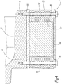
- the conductive cover 110 is preferably made of the same material as the conductive structure 86. elsewhere, the conductive cover 110 is mounted on the upper face 26 with the aid of eight bolts 112, two of which are shown in FIG. figure 4 , or with the aid of any other suitable through conductor fixing element, bearing on the four corners of this face 26.
- the four corners are slightly protruding relative to a central portion of the face 26, so that the insulating layer 108 is advantageously crushed by the cover 110, which makes it possible to seal the closing the frame 24 by the cover 110.
- These conductive fixing means pass right through the insulating frame 24, for example through eight through holes 114 of the frame 24.
- the terminal block 3 may advantageously be fixed to the motor 5 by the intermediate of these fixing means, as visible on the figure 4 .
- the conductive fastening means are in electrical contact with the conductive base 90.
- the conductive base 90 and the conductive cover 110 are thus electrically connected by the through fastening means.
- a number of fixing means and through holes less than or greater than eight can be implemented without departing from the scope of the invention.
- any suitable means can be used to electrically connect the cover 110 to the base 90.
- Grounding this faulty element allows detection of the fault by a power train of the electrically-propelled vehicle, or any other safety device known as such that this vehicle is provided with.
- the safety device then advantageously controls an isolation of the electric motor 5.
- the vehicle can, in this case, generally continue its journey with its insulated motor 5, especially in the case where the vehicle comprises other traction motors.
- the cost of repair following the appearance of the defect is thus reduced, the electric traction vehicle being made available despite electrical faults likely to occur within its traction motor.
- the presence of the insulating partitions 44 to 50 makes it possible to reduce the overall bulk of the terminal block 3, compared to a case where the conductive cores 92 to 98 would be used without an insulating partition, that is to say, bare and remote from the connection plates 56 to 60, especially since the insulating material of the partitions makes it possible to have isolation distances between the parts electrically connected to the winding and the mass of the motor which are much shorter than with partitions made of conductive material.
- the terminal block 3 described above is also suitable for any electrical machine with at least two phases, with two corresponding phase terminals, or more than three phase terminals, with as many phase terminals as necessary.
- the terminal block comprises as many connection plates as phase terminals emanating from the electrical machine, so that as many secondary terminals for supplying the phases can be connected to them.
- the terminal block comprises intermediate partitions interposed each between two of the connection plates, and each containing a conductive intermediate core connected to the ground of the electric machine.
- the terminal block comprises as many glands as the motor comprises phases. Alternatively to glands, any suitable means for sealing the secondary terminals can be implemented.
- the terminal block 3 described above can be used in an onboard electric vehicle, for example on batteries.
- the terminal block 3 may alternatively be used on a vehicle with electric transmission, comprising an electric traction motor powered by a generator powered by a thermal engine of the vehicle.
- the terminal block 3 may alternatively be used in an electrical installation which is not a vehicle, but which is for example fixed, and which includes an electrical machine according to the foregoing.
- the insulating frame 24 may be made of one or more other insulating materials, such as a polymer or a suitable composite material.
- the conductive cores 92 to 98 are integrated in the insulating frame 24, so that the conductive base 90 is attached to both the insulating frame 24 and the conductive cores 92 to 98.
- each secondary terminal 18, 20 and 22 is electrically connected with its corresponding phase terminal 10, 12 or 14 via the conductive insert 57, 59 or 61 of one of the connection plates 56, 58 or 60, the electrical power supply of the electrical machine passing through in this case the connection plates.
- the secondary terminals 18, 20 and 22 are not necessarily in physical contact with the phase terminals 10, 12 and 14, the electrical energy being transmitted through the conductive inserts 57, 59 and 61.
- the electrical continuity between each secondary terminal 18, 20 and 22 and the phase terminal concerned is provided by the connecting plate 56, 58 or 60 concerned.
- the terminal block 3 can be implemented in a fixed electrical installation comprising an electric machine as described above.
- the electric machine is an electric energy generator, in particular a synchronous generator with permanent magnets.
- the generator being designed to generate electrical energy, which is emitted at its phase terminals. This electrical energy is transmitted via the terminal block 3 to secondary terminals for receiving electrical energy, belonging to a receiving electrical equipment, such as a transformer.
- the electric generator can be implemented in the vehicle V described above, or in any other electrical installation subject to the formation of arcs.
Landscapes
- Engineering & Computer Science (AREA)
- Power Engineering (AREA)
- Motor Or Generator Frames (AREA)
- Connections Arranged To Contact A Plurality Of Conductors (AREA)
- Electric Propulsion And Braking For Vehicles (AREA)
Claims (10)
- Anschlussblock (3) für eine elektrische Maschine (5), wie etwa einen elektrischen Antriebsmotor oder einen Generator, wobei die elektrische Maschine mindestens zwei Phasenanschlussklemmen (10, 12, 14) aufweist, wobei der Anschlussblock mindestens zwei Verbindungsstücke (56, 58, 60) und für jedes Verbindungsstück Mittel (68, 70, 72) zum Befestigen einer der Phasenanschlussklemmen (10, 12, 14) und einem Sekundäranschluss (18, 20, 22) zur elektrischen Energieversorgung der betreffenden Phasenanschlussklemme und/oder zum Empfangen von an dieser abgegebenen elektrischen Energie umfasst, wobei mindestens eine isolierende Zwischenwand (44, 46) des Anschlussblocks zwischen den Verbindungsstücken angeordnet ist, wobei dieser Anschlussblock (3) dadurch gekennzeichnet ist, dass er einen leitenden Zwischensteg (96, 98) umfasst, der an jeder isolierenden Zwischenwand (44, 46) angeordnet ist und der ausgebildet ist, mit einer elektrischen Masse der elektrischen Maschine elektrisch verbunden zu werden.
- Anschlussblock (3) nach Anspruch 1, dadurch gekennzeichnet, dass er zwei isolierende Seitenwände (48, 50) umfasst, die beidseitig der Verbindungsstücke (56, 58, 60) angeordnet sind, wobei sie parallel zu jeder isolierenden Zwischenwand (44, 46) liegen, und dass er zwei leitende Seitenstege (92, 94) umfasst, die jeweils an den isolierenden Seitenwänden angeordnet sind und die elektrisch mit jedem leitenden Zwischensteg (96, 98) verbunden sind.
- Anschlussblock (3) nach einem beliebigen der vorhergehenden Ansprüche, dadurch gekennzeichnet, dass er umfasst:- einen isolierenden Rahmen (24), der mit den Verbindungsstücken (56, 58, 60) verbunden ist und der die isolierende Zwischenwand (44, 46) einschließt, und- ein leitendes Gebilde (86), das mindestens jeden leitenden Zwischensteg (96, 98) und eine leitende Grundplatte (90), auf der jeder leitende Zwischensteg dauerhaft befestigt ist, einschließt, wobei das leitende Gebilde an dem isolierenden Rahmen angebracht ist.
- Anschlussblock (3) nach Anspruch 3, dadurch gekennzeichnet, dass das leitende Gebilde außerdem eine leitende Abdeckung (110) umfasst, die elektrisch mit der leitenden Grundplatte (90), vorzugsweise über Befestigungselemente (112), verbunden ist, die den isolierenden Rahmen (24) durchgreifen und sich zwischen der leitenden Grundplatte und der leitenden Abdeckung erstrecken.
- Anschlussblock (3) nach einem beliebigen der vorhergehenden Ansprüche, dadurch gekennzeichnet, dass die Verbindungsstücke (56, 58, 60) leitend sind, dass die Befestigungsmittel (68, 70, 72) so ausgebildet sind, dass jeder Sekundäranschluss (18, 20, 22) elektrisch mit der betreffenden Anschlussklemme (10, 12, 14) über eines der Verbindungsstücke verbunden ist, und dass die elektrische Durchgängigkeit zwischen jedem Sekundäranschluss und der betreffenden Phasenanschlussklemme durch das betreffende Verbindungsstück sichergestellt ist.
- Anschlussblock (3) nach einem beliebigen der Anschlüsse 1 bis 4, dadurch gekennzeichnet, dass die Befestigungsmittel (68, 70, 72) so ausgebildet sind, dass jeder Sekundäranschluss (18, 20, 22) elektrisch mit der betreffenden Phasenanschlussklemme (10, 12, 14) durch physisches Inkontaktbringen jedes Sekundäranschlusses mit einer der Phasenanschlussklemmen verbunden ist.
- Anschlussblock (3) nach einem beliebigen der vorhergehenden Ansprüche, dadurch gekennzeichnet, dass jeder Sekundäranschluss (18, 20, 22) ein Verbindungskabel (18, 20, 22) umfasst und dass der Anschlussblock (3) mindestens zwei Kabelverschraubungen (74, 76, 78) umfasst, die ausgebildet sind, jeweils eines der Verbindungskabel aufzunehmen.
- Anschlussblock (3) nach einem beliebigen der vorhergehenden Ansprüche, dadurch gekennzeichnet, dass:- drei Phasenanschlussklemmen (10, 12, 14), drei Sekundäranschlüsse (18, 20, 22), drei Verbindungsstücke (56, 58, 60), zwei isolierende Zwischenwände (44, 46) und zwei leitende Zwischenstege (96, 98) vorgesehen sind,- jeder leitende Zwischensteg (96, 98) an einer der isolierenden Zwischenwände angeordnet ist und- jede isolierende Zwischenwand (44, 46) zwischen zwei Verbindungsstücken angeordnet ist.
- Elektrische Maschine (5), wie etwa ein elektrischer Antriebsmotor oder ein Generator, wobei die elektrische Maschine mindestens zwei Phasenanschlussklemmen (10, 12, 14) und eine elektrische Masse aufweist, wobei die elektrische Maschine einen Anschlussblock (3) gemäß einem der vorhergehenden Ansprüche umfasst, jede der Phasenanschlussklemmen an einem der Verbindungsstücke (56, 58, 60) durch Befestigungsmittel (68, 70, 72) befestigt ist und jeder leitende Zwischensteg (96, 98) elektrisch mit der elektrischen Masse verbunden ist.
- Fahrzeug (V) mit elektrischem Antrieb, eine elektrische Maschine (5) gemäß dem vorhergehenden Anspruch umfassend, wobei die elektrische Maschine einen elektrischen Antriebsmotor des Fahrzeugs bildet, das Fahrzeug einen Leistungskreis umfasst, der eine elektrische Masse einschließt, an die der elektrische Antriebsmotor elektrisch angeschlossen ist, wobei der Leistungskreis eine Versorgungsvorrichtung, wie etwa einen Wechselrichter, mit mindestens zwei Sekundäranschlüsse (18, 20, 22) zur Versorgung der Phasenanschlussklemmen des elektrischen Antriebsmotors mit elektrischer Energie aufweist, wobei jeder Sekundäranschluss an einem der Verbindungsstücke (56, 58, 60) durch die Befestigungsmittel (68, 70, 72) befestigt ist.
Priority Applications (1)
| Application Number | Priority Date | Filing Date | Title |
|---|---|---|---|
| PL17168413T PL3240154T3 (pl) | 2016-04-29 | 2017-04-27 | Listwa zaciskowa, maszyna elektryczna zawierająca taką listwę zaciskową i pojazd zawierający taką maszynę elektryczną |
Applications Claiming Priority (1)
| Application Number | Priority Date | Filing Date | Title |
|---|---|---|---|
| FR1653862A FR3050885B1 (fr) | 2016-04-29 | 2016-04-29 | Bornier, machine electrique comprenant un tel bornier et vehicule comprenant une telle machine electrique |
Publications (2)
| Publication Number | Publication Date |
|---|---|
| EP3240154A1 EP3240154A1 (de) | 2017-11-01 |
| EP3240154B1 true EP3240154B1 (de) | 2018-09-05 |
Family
ID=56411743
Family Applications (1)
| Application Number | Title | Priority Date | Filing Date |
|---|---|---|---|
| EP17168413.7A Active EP3240154B1 (de) | 2016-04-29 | 2017-04-27 | Terminalblock, elektrische maschine mit einem solchen terminalblock und fahrzeug mit einer solchen elektrischen maschine |
Country Status (5)
| Country | Link |
|---|---|
| EP (1) | EP3240154B1 (de) |
| JP (1) | JP2017200434A (de) |
| CN (1) | CN107404178A (de) |
| FR (1) | FR3050885B1 (de) |
| PL (1) | PL3240154T3 (de) |
Families Citing this family (3)
| Publication number | Priority date | Publication date | Assignee | Title |
|---|---|---|---|---|
| FR3092705B1 (fr) * | 2019-02-12 | 2021-02-26 | Alstom Transp Tech | Dispositif de protection d’au moins deux câbles électriques contre un arc électrique |
| FR3118328B1 (fr) * | 2020-12-22 | 2023-11-24 | Alstom Transp Tech | Contacteur électrique d’une ligne d’alimentation à trois phases électriques pour un véhicule et véhicule comprenant un tel contacteur |
| FR3140223B1 (fr) | 2022-09-26 | 2025-07-04 | Alstom Holdings | Assemblage de connexion électrique pour moteur électrique de traction |
Family Cites Families (6)
| Publication number | Priority date | Publication date | Assignee | Title |
|---|---|---|---|---|
| US4675778A (en) * | 1985-03-21 | 1987-06-23 | Northern Telecom Limited | Overload protector for communications systems |
| FR2671671A1 (fr) * | 1991-01-10 | 1992-07-17 | Mars Actel | Reglette de raccordement a protections semi-integrees. |
| US6188560B1 (en) * | 1994-10-21 | 2001-02-13 | 3M Innovative Properties Company | Multi-wire terminal block employing removable surge protector |
| KR20090006635U (ko) * | 2007-12-28 | 2009-07-02 | 채석 | 케이블 접속 단자대 |
| JP5294034B2 (ja) * | 2009-11-13 | 2013-09-18 | 住友電装株式会社 | 端子台 |
| US9537363B2 (en) * | 2014-04-30 | 2017-01-03 | Honeywell International Inc. | Electric motor-driven compressor having an electrical terminal block assembly |
-
2016
- 2016-04-29 FR FR1653862A patent/FR3050885B1/fr not_active Expired - Fee Related
-
2017
- 2017-04-27 PL PL17168413T patent/PL3240154T3/pl unknown
- 2017-04-27 EP EP17168413.7A patent/EP3240154B1/de active Active
- 2017-04-28 JP JP2017089528A patent/JP2017200434A/ja active Pending
- 2017-04-28 CN CN201710291945.7A patent/CN107404178A/zh active Pending
Also Published As
| Publication number | Publication date |
|---|---|
| FR3050885B1 (fr) | 2018-05-18 |
| JP2017200434A (ja) | 2017-11-02 |
| EP3240154A1 (de) | 2017-11-01 |
| PL3240154T3 (pl) | 2019-02-28 |
| FR3050885A1 (fr) | 2017-11-03 |
| CN107404178A (zh) | 2017-11-28 |
Similar Documents
| Publication | Publication Date | Title |
|---|---|---|
| EP3240154B1 (de) | Terminalblock, elektrische maschine mit einem solchen terminalblock und fahrzeug mit einer solchen elektrischen maschine | |
| EP2634875B1 (de) | Messfeldblock für Mittelspannungsschaltanlage | |
| EP3323175B1 (de) | An mehrere kabel mit schutz gegen schäden durch fremdkörper anschliessbare elektrische verbindungsvorrichtung | |
| EP2720329B1 (de) | Mittelspannungsschaltanlage | |
| EP1043186A1 (de) | Bodenstromversorgungseinrichtung für ein elektrisches Fahrzeug | |
| FR2977085A1 (fr) | Dispositif de raccordement electrique d'au moins un conducteur a respectivement au moins une plage de contact d'un appareil electrique et appareil electrique le comportant. | |
| CA2495987C (fr) | Dispositif de retour d'alimentation electrique pour equipements avioniques | |
| EP2634874B1 (de) | Gasentladungsvorrichtung für Mittelspannungs- Funktionseinheit und Verteilungsunterstation damit | |
| EP2634876B1 (de) | Mittelspannungsverbindungsleiste mit einer ebener Schnittstelle und mit einer konischer Steckverbindung | |
| EP2634869B1 (de) | Stecker mit flacher Anschlussschnittstelle und eine Mittelspannungsanlage mit einem derartigen Stecker. | |
| EP3476665B1 (de) | Elektrische isolierleiste, insbesondere für ein elektronisches leistungsmodul eines wechselrichters | |
| CA3040557A1 (fr) | Atterrisseur pourvu d'un dispositif pare-foudre | |
| FR2779279A1 (fr) | Barre de distribution d'energie electrique | |
| EP4078721A1 (de) | Kraftfahrzeugbatterieanordnung mit verriegelungsmitteln zum schutz der beiden anschlussklemmen | |
| FR3140223A1 (fr) | Assemblage de connexion électrique pour moteur électrique de traction | |
| FR2984616A1 (fr) | Ventilation pour appareil de deconnexion electrique | |
| EP3232524B1 (de) | Einschub-leistungsschalter mit einer verbesserten rückplatte | |
| EP3599629B1 (de) | Elektrische trennschaltervorrichtung für fahrzeug und entsprechendes fahrzeug | |
| FR3071108A1 (fr) | Systeme de fixation d’une barre omnibus de vehicule automobile | |
| FR3076093A1 (fr) | Dispositif de mise a la terre d'une catenaire comprenant des moyens conducteurs d'electricite securises | |
| EP4371222A1 (de) | Modulare verbindungen für einen motor und eine leistungselektronikeinheit | |
| EP1443602A1 (de) | Elektrischer Verbinder zum Verbinden eines Kabels zwischen zwei Wagen eines Schienenfahrzeuges | |
| EP0338948A1 (de) | Vorrichtung zum Befestigen von Stromschienen in einem elektrischen Versorgungsmodul | |
| WO2019053353A1 (fr) | Systeme de protection et d'isolation d'une barre omnibus de vehicule automobile | |
| FR3056850A3 (fr) | Systeme d'actionnement electrique pour vehicule |
Legal Events
| Date | Code | Title | Description |
|---|---|---|---|
| PUAI | Public reference made under article 153(3) epc to a published international application that has entered the european phase |
Free format text: ORIGINAL CODE: 0009012 |
|
| STAA | Information on the status of an ep patent application or granted ep patent |
Free format text: STATUS: THE APPLICATION HAS BEEN PUBLISHED |
|
| STAA | Information on the status of an ep patent application or granted ep patent |
Free format text: STATUS: REQUEST FOR EXAMINATION WAS MADE |
|
| AK | Designated contracting states |
Kind code of ref document: A1 Designated state(s): AL AT BE BG CH CY CZ DE DK EE ES FI FR GB GR HR HU IE IS IT LI LT LU LV MC MK MT NL NO PL PT RO RS SE SI SK SM TR |
|
| AX | Request for extension of the european patent |
Extension state: BA ME |
|
| 17P | Request for examination filed |
Effective date: 20171011 |
|
| RBV | Designated contracting states (corrected) |
Designated state(s): AL AT BE BG CH CY CZ DE DK EE ES FI FR GB GR HR HU IE IS IT LI LT LU LV MC MK MT NL NO PL PT RO RS SE SI SK SM TR |
|
| GRAP | Despatch of communication of intention to grant a patent |
Free format text: ORIGINAL CODE: EPIDOSNIGR1 |
|
| STAA | Information on the status of an ep patent application or granted ep patent |
Free format text: STATUS: GRANT OF PATENT IS INTENDED |
|
| INTG | Intention to grant announced |
Effective date: 20180214 |
|
| GRAS | Grant fee paid |
Free format text: ORIGINAL CODE: EPIDOSNIGR3 |
|
| GRAA | (expected) grant |
Free format text: ORIGINAL CODE: 0009210 |
|
| STAA | Information on the status of an ep patent application or granted ep patent |
Free format text: STATUS: THE PATENT HAS BEEN GRANTED |
|
| AK | Designated contracting states |
Kind code of ref document: B1 Designated state(s): AL AT BE BG CH CY CZ DE DK EE ES FI FR GB GR HR HU IE IS IT LI LT LU LV MC MK MT NL NO PL PT RO RS SE SI SK SM TR |
|
| REG | Reference to a national code |
Ref country code: GB Ref legal event code: FG4D Free format text: NOT ENGLISH |
|
| REG | Reference to a national code |
Ref country code: CH Ref legal event code: EP |
|
| REG | Reference to a national code |
Ref country code: AT Ref legal event code: REF Ref document number: 1038981 Country of ref document: AT Kind code of ref document: T Effective date: 20180915 |
|
| REG | Reference to a national code |
Ref country code: IE Ref legal event code: FG4D Free format text: LANGUAGE OF EP DOCUMENT: FRENCH |
|
| REG | Reference to a national code |
Ref country code: DE Ref legal event code: R096 Ref document number: 602017000348 Country of ref document: DE |
|
| REG | Reference to a national code |
Ref country code: CH Ref legal event code: NV Representative=s name: MICHELI AND CIE SA, CH |
|
| REG | Reference to a national code |
Ref country code: NL Ref legal event code: MP Effective date: 20180905 |
|
| REG | Reference to a national code |
Ref country code: LT Ref legal event code: MG4D |
|
| PG25 | Lapsed in a contracting state [announced via postgrant information from national office to epo] |
Ref country code: LT Free format text: LAPSE BECAUSE OF FAILURE TO SUBMIT A TRANSLATION OF THE DESCRIPTION OR TO PAY THE FEE WITHIN THE PRESCRIBED TIME-LIMIT Effective date: 20180905 Ref country code: GR Free format text: LAPSE BECAUSE OF FAILURE TO SUBMIT A TRANSLATION OF THE DESCRIPTION OR TO PAY THE FEE WITHIN THE PRESCRIBED TIME-LIMIT Effective date: 20181206 Ref country code: FI Free format text: LAPSE BECAUSE OF FAILURE TO SUBMIT A TRANSLATION OF THE DESCRIPTION OR TO PAY THE FEE WITHIN THE PRESCRIBED TIME-LIMIT Effective date: 20180905 Ref country code: BG Free format text: LAPSE BECAUSE OF FAILURE TO SUBMIT A TRANSLATION OF THE DESCRIPTION OR TO PAY THE FEE WITHIN THE PRESCRIBED TIME-LIMIT Effective date: 20181205 Ref country code: RS Free format text: LAPSE BECAUSE OF FAILURE TO SUBMIT A TRANSLATION OF THE DESCRIPTION OR TO PAY THE FEE WITHIN THE PRESCRIBED TIME-LIMIT Effective date: 20180905 Ref country code: SE Free format text: LAPSE BECAUSE OF FAILURE TO SUBMIT A TRANSLATION OF THE DESCRIPTION OR TO PAY THE FEE WITHIN THE PRESCRIBED TIME-LIMIT Effective date: 20180905 Ref country code: NO Free format text: LAPSE BECAUSE OF FAILURE TO SUBMIT A TRANSLATION OF THE DESCRIPTION OR TO PAY THE FEE WITHIN THE PRESCRIBED TIME-LIMIT Effective date: 20181205 |
|
| PG25 | Lapsed in a contracting state [announced via postgrant information from national office to epo] |
Ref country code: LV Free format text: LAPSE BECAUSE OF FAILURE TO SUBMIT A TRANSLATION OF THE DESCRIPTION OR TO PAY THE FEE WITHIN THE PRESCRIBED TIME-LIMIT Effective date: 20180905 Ref country code: AL Free format text: LAPSE BECAUSE OF FAILURE TO SUBMIT A TRANSLATION OF THE DESCRIPTION OR TO PAY THE FEE WITHIN THE PRESCRIBED TIME-LIMIT Effective date: 20180905 Ref country code: HR Free format text: LAPSE BECAUSE OF FAILURE TO SUBMIT A TRANSLATION OF THE DESCRIPTION OR TO PAY THE FEE WITHIN THE PRESCRIBED TIME-LIMIT Effective date: 20180905 |
|
| PG25 | Lapsed in a contracting state [announced via postgrant information from national office to epo] |
Ref country code: CZ Free format text: LAPSE BECAUSE OF FAILURE TO SUBMIT A TRANSLATION OF THE DESCRIPTION OR TO PAY THE FEE WITHIN THE PRESCRIBED TIME-LIMIT Effective date: 20180905 Ref country code: IS Free format text: LAPSE BECAUSE OF FAILURE TO SUBMIT A TRANSLATION OF THE DESCRIPTION OR TO PAY THE FEE WITHIN THE PRESCRIBED TIME-LIMIT Effective date: 20190105 Ref country code: EE Free format text: LAPSE BECAUSE OF FAILURE TO SUBMIT A TRANSLATION OF THE DESCRIPTION OR TO PAY THE FEE WITHIN THE PRESCRIBED TIME-LIMIT Effective date: 20180905 Ref country code: NL Free format text: LAPSE BECAUSE OF FAILURE TO SUBMIT A TRANSLATION OF THE DESCRIPTION OR TO PAY THE FEE WITHIN THE PRESCRIBED TIME-LIMIT Effective date: 20180905 Ref country code: RO Free format text: LAPSE BECAUSE OF FAILURE TO SUBMIT A TRANSLATION OF THE DESCRIPTION OR TO PAY THE FEE WITHIN THE PRESCRIBED TIME-LIMIT Effective date: 20180905 |
|
| PG25 | Lapsed in a contracting state [announced via postgrant information from national office to epo] |
Ref country code: SM Free format text: LAPSE BECAUSE OF FAILURE TO SUBMIT A TRANSLATION OF THE DESCRIPTION OR TO PAY THE FEE WITHIN THE PRESCRIBED TIME-LIMIT Effective date: 20180905 Ref country code: SK Free format text: LAPSE BECAUSE OF FAILURE TO SUBMIT A TRANSLATION OF THE DESCRIPTION OR TO PAY THE FEE WITHIN THE PRESCRIBED TIME-LIMIT Effective date: 20180905 Ref country code: PT Free format text: LAPSE BECAUSE OF FAILURE TO SUBMIT A TRANSLATION OF THE DESCRIPTION OR TO PAY THE FEE WITHIN THE PRESCRIBED TIME-LIMIT Effective date: 20190105 |
|
| REG | Reference to a national code |
Ref country code: DE Ref legal event code: R097 Ref document number: 602017000348 Country of ref document: DE |
|
| PLBE | No opposition filed within time limit |
Free format text: ORIGINAL CODE: 0009261 |
|
| STAA | Information on the status of an ep patent application or granted ep patent |
Free format text: STATUS: NO OPPOSITION FILED WITHIN TIME LIMIT |
|
| PG25 | Lapsed in a contracting state [announced via postgrant information from national office to epo] |
Ref country code: ES Free format text: LAPSE BECAUSE OF FAILURE TO SUBMIT A TRANSLATION OF THE DESCRIPTION OR TO PAY THE FEE WITHIN THE PRESCRIBED TIME-LIMIT Effective date: 20180905 Ref country code: DK Free format text: LAPSE BECAUSE OF FAILURE TO SUBMIT A TRANSLATION OF THE DESCRIPTION OR TO PAY THE FEE WITHIN THE PRESCRIBED TIME-LIMIT Effective date: 20180905 |
|
| 26N | No opposition filed |
Effective date: 20190606 |
|
| PG25 | Lapsed in a contracting state [announced via postgrant information from national office to epo] |
Ref country code: SI Free format text: LAPSE BECAUSE OF FAILURE TO SUBMIT A TRANSLATION OF THE DESCRIPTION OR TO PAY THE FEE WITHIN THE PRESCRIBED TIME-LIMIT Effective date: 20180905 |
|
| REG | Reference to a national code |
Ref country code: BE Ref legal event code: MM Effective date: 20190430 |
|
| PG25 | Lapsed in a contracting state [announced via postgrant information from national office to epo] |
Ref country code: LU Free format text: LAPSE BECAUSE OF NON-PAYMENT OF DUE FEES Effective date: 20190427 Ref country code: MC Free format text: LAPSE BECAUSE OF FAILURE TO SUBMIT A TRANSLATION OF THE DESCRIPTION OR TO PAY THE FEE WITHIN THE PRESCRIBED TIME-LIMIT Effective date: 20180905 |
|
| PG25 | Lapsed in a contracting state [announced via postgrant information from national office to epo] |
Ref country code: BE Free format text: LAPSE BECAUSE OF NON-PAYMENT OF DUE FEES Effective date: 20190430 |
|
| PG25 | Lapsed in a contracting state [announced via postgrant information from national office to epo] |
Ref country code: TR Free format text: LAPSE BECAUSE OF FAILURE TO SUBMIT A TRANSLATION OF THE DESCRIPTION OR TO PAY THE FEE WITHIN THE PRESCRIBED TIME-LIMIT Effective date: 20180905 |
|
| PG25 | Lapsed in a contracting state [announced via postgrant information from national office to epo] |
Ref country code: IE Free format text: LAPSE BECAUSE OF NON-PAYMENT OF DUE FEES Effective date: 20190427 |
|
| PG25 | Lapsed in a contracting state [announced via postgrant information from national office to epo] |
Ref country code: CY Free format text: LAPSE BECAUSE OF FAILURE TO SUBMIT A TRANSLATION OF THE DESCRIPTION OR TO PAY THE FEE WITHIN THE PRESCRIBED TIME-LIMIT Effective date: 20180905 |
|
| REG | Reference to a national code |
Ref country code: AT Ref legal event code: UEP Ref document number: 1038981 Country of ref document: AT Kind code of ref document: T Effective date: 20180905 |
|
| PG25 | Lapsed in a contracting state [announced via postgrant information from national office to epo] |
Ref country code: MT Free format text: LAPSE BECAUSE OF FAILURE TO SUBMIT A TRANSLATION OF THE DESCRIPTION OR TO PAY THE FEE WITHIN THE PRESCRIBED TIME-LIMIT Effective date: 20180905 Ref country code: HU Free format text: LAPSE BECAUSE OF FAILURE TO SUBMIT A TRANSLATION OF THE DESCRIPTION OR TO PAY THE FEE WITHIN THE PRESCRIBED TIME-LIMIT; INVALID AB INITIO Effective date: 20170427 |
|
| PG25 | Lapsed in a contracting state [announced via postgrant information from national office to epo] |
Ref country code: MK Free format text: LAPSE BECAUSE OF FAILURE TO SUBMIT A TRANSLATION OF THE DESCRIPTION OR TO PAY THE FEE WITHIN THE PRESCRIBED TIME-LIMIT Effective date: 20180905 |
|
| P01 | Opt-out of the competence of the unified patent court (upc) registered |
Effective date: 20230823 |
|
| REG | Reference to a national code |
Ref country code: GB Ref legal event code: 732E Free format text: REGISTERED BETWEEN 20250213 AND 20250219 |
|
| PGFP | Annual fee paid to national office [announced via postgrant information from national office to epo] |
Ref country code: PL Payment date: 20250418 Year of fee payment: 9 Ref country code: DE Payment date: 20250422 Year of fee payment: 9 |
|
| PGFP | Annual fee paid to national office [announced via postgrant information from national office to epo] |
Ref country code: IT Payment date: 20250424 Year of fee payment: 9 |
|
| PGFP | Annual fee paid to national office [announced via postgrant information from national office to epo] |
Ref country code: FR Payment date: 20250425 Year of fee payment: 9 |
|
| PGFP | Annual fee paid to national office [announced via postgrant information from national office to epo] |
Ref country code: CH Payment date: 20250501 Year of fee payment: 9 |
|
| PGFP | Annual fee paid to national office [announced via postgrant information from national office to epo] |
Ref country code: AT Payment date: 20250423 Year of fee payment: 9 |
|
| PGFP | Annual fee paid to national office [announced via postgrant information from national office to epo] |
Ref country code: GB Payment date: 20260306 Year of fee payment: 10 |