EP3240121A1 - Lichtführungsschiene und verbinderanordnung - Google Patents
Lichtführungsschiene und verbinderanordnung Download PDFInfo
- Publication number
- EP3240121A1 EP3240121A1 EP16202319.6A EP16202319A EP3240121A1 EP 3240121 A1 EP3240121 A1 EP 3240121A1 EP 16202319 A EP16202319 A EP 16202319A EP 3240121 A1 EP3240121 A1 EP 3240121A1
- Authority
- EP
- European Patent Office
- Prior art keywords
- light guide
- guide bar
- connector
- connectors
- lateral walls
- Prior art date
- Legal status (The legal status is an assumption and is not a legal conclusion. Google has not performed a legal analysis and makes no representation as to the accuracy of the status listed.)
- Granted
Links
Images


Classifications
-
- F—MECHANICAL ENGINEERING; LIGHTING; HEATING; WEAPONS; BLASTING
- F21—LIGHTING
- F21S—NON-PORTABLE LIGHTING DEVICES; SYSTEMS THEREOF; VEHICLE LIGHTING DEVICES SPECIALLY ADAPTED FOR VEHICLE EXTERIORS
- F21S4/00—Lighting devices or systems using a string or strip of light sources
- F21S4/20—Lighting devices or systems using a string or strip of light sources with light sources held by or within elongate supports
- F21S4/28—Lighting devices or systems using a string or strip of light sources with light sources held by or within elongate supports rigid, e.g. LED bars
-
- H—ELECTRICITY
- H01—ELECTRIC ELEMENTS
- H01R—ELECTRICALLY-CONDUCTIVE CONNECTIONS; STRUCTURAL ASSOCIATIONS OF A PLURALITY OF MUTUALLY-INSULATED ELECTRICAL CONNECTING ELEMENTS; COUPLING DEVICES; CURRENT COLLECTORS
- H01R13/00—Details of coupling devices of the kinds covered by groups H01R12/70 or H01R24/00 - H01R33/00
- H01R13/66—Structural association with built-in electrical component
- H01R13/717—Structural association with built-in electrical component with built-in light source
- H01R13/7172—Conduits for light transmission
-
- F—MECHANICAL ENGINEERING; LIGHTING; HEATING; WEAPONS; BLASTING
- F21—LIGHTING
- F21V—FUNCTIONAL FEATURES OR DETAILS OF LIGHTING DEVICES OR SYSTEMS THEREOF; STRUCTURAL COMBINATIONS OF LIGHTING DEVICES WITH OTHER ARTICLES, NOT OTHERWISE PROVIDED FOR
- F21V33/00—Structural combinations of lighting devices with other articles, not otherwise provided for
-
- G—PHYSICS
- G02—OPTICS
- G02B—OPTICAL ELEMENTS, SYSTEMS OR APPARATUS
- G02B6/00—Light guides; Structural details of arrangements comprising light guides and other optical elements, e.g. couplings
- G02B6/0001—Light guides; Structural details of arrangements comprising light guides and other optical elements, e.g. couplings specially adapted for lighting devices or systems
- G02B6/0011—Light guides; Structural details of arrangements comprising light guides and other optical elements, e.g. couplings specially adapted for lighting devices or systems the light guides being planar or of plate-like form
- G02B6/0075—Arrangements of multiple light guides
- G02B6/0078—Side-by-side arrangements, e.g. for large area displays
-
- G—PHYSICS
- G02—OPTICS
- G02B—OPTICAL ELEMENTS, SYSTEMS OR APPARATUS
- G02B6/00—Light guides; Structural details of arrangements comprising light guides and other optical elements, e.g. couplings
- G02B6/0001—Light guides; Structural details of arrangements comprising light guides and other optical elements, e.g. couplings specially adapted for lighting devices or systems
- G02B6/0011—Light guides; Structural details of arrangements comprising light guides and other optical elements, e.g. couplings specially adapted for lighting devices or systems the light guides being planar or of plate-like form
- G02B6/0081—Mechanical or electrical aspects of the light guide and light source in the lighting device peculiar to the adaptation to planar light guides, e.g. concerning packaging
- G02B6/0086—Positioning aspects
- G02B6/0088—Positioning aspects of the light guide or other optical sheets in the package
Definitions
- the invention relates to a light guide bar and a connector assembly, and particularly to a light guide bar that can be easily fixed between two connectors and a connector assembly including the light guide bar and the two connectors.
- screw tightening screws tightening, adhesion, hot riveting and so on are common methods for fixing a component onto other components (e.g., connector) on a main board.
- screw tightening it is required to respectively drill screw holes and through holes on two components and then tighten screws to fix the two components.
- adhesion it may be difficult to determine whether the components are properly positioned if the space is limited, and overflow of the adhesive may also occur sometimes.
- hot riveting the components need to be heated to be melted and deformed so as to be combined, which may be troublesome for fabrication.
- the connector is a memory connector
- a high-end memory module may be provided with a fan on one side to quickly dissipate the heat generated by the chip on the memory module by air circulation, this type of memory module may be heavier.
- the memory module When the memory module is inserted into the memory connector on the main board, it may cause the case of the memory connector to crack. Thus, how to prevent crack of the connector is also an issue that needs to be addressed.
- the invention provides a light guide bar that can be easily fixed between two connectors for guiding a light between the two connectors to achieve effects of indication and decoration and prevent crack of the connectors.
- the invention provides a connector assembly that includes the light guide bar and the two connectors.
- the invention provides a light guide bar that is adapted to be disposed between two connectors.
- the two connectors are disposed on a main board.
- Each of the connectors includes a connector lateral wall.
- At least one of the connectors includes a positioning protrusion that protrudes from the connector lateral wall.
- the light guide bar includes a light guide bar body.
- the light guide bar body includes two opposite light guide bar lateral walls and at least one positioning recess. Each positioning recess is formed on one of the light guide bar lateral walls. The positioning recess is adapted to be positioned on the positioning protrusion of the connector.
- the two connectors respectively include the two opposite connector lateral walls and the two positioning protrusions that protrude from the two connector lateral walls
- the light guide bar body includes the two positioning recesses that respectively formed on the two light guide bar lateral walls and are adapted to be positioned on the two positioning protrusions of the two connectors.
- the light guide bar body includes a light guide bar bottom surface connecting the two light guide bar lateral walls, the light guide bar includes at least one guiding part, and each guiding part is disposed on one of the light guide bar lateral walls and located between the positioning recess and the light guide bar bottom surface.
- the positioning recess is surrounded and defined by a plurality of restricting surfaces.
- the light guide bar body includes a plurality of notches located on a surface of the light guide bar body or inside the light guide bar body.
- the light guide bar body includes four light guide bar lateral walls, each of the light guide bar lateral walls is connected to the two adjacent light guide bar lateral walls respectively, and one of the light guide bar lateral walls that does not include the positioning recess includes a protruding or recessed pulling part.
- one of the light guide bar lateral walls is adapted to introduce light emitted from a light source that is disposed on the main board at a position close to the two connectors, and the light guide bar lateral wall is located beside the light source.
- the invention provides a connector assembly that is adapted to be disposed on a main board.
- the connector assembly includes at least two connectors and at least one light guide bar.
- the connectors are arranged in parallel and each include a connector lateral wall, and at least one of the connectors includes a positioning protrusion that protrudes from the connector lateral wall.
- Each light guide bar is disposed between adjacent two of the connectors and includes a light guide bar body.
- the light guide bar body includes two opposite light guide bar lateral walls and at least one positioning recess. Each positioning recess is formed on one of the light guide bar lateral walls.
- the positioning recess is adapted to be positioned on the positioning protrusion of the connector.
- adjacent two of the connectors respectively include the two opposite connector lateral walls and the two positioning protrusions that protrude from the two connector lateral walls
- each light guide bar body includes the two positioning recesses that respectively formed on the two light guide bar lateral walls and are adapted to be positioned on the two positioning protrusions of the adjacent two of the connectors.
- each light guide bar body includes a light guide bar bottom surface connecting the two light guide bar lateral walls, each light guide bar includes at least one guiding part, and each guiding part is disposed on one of the light guide bar lateral walls and located between the positioning recess and the light guide bar bottom surface.
- the positioning recess is surrounded and defined by a plurality of restricting surfaces.
- each light guide bar body includes a plurality of notches located on a surface of the light guide bar body or inside the light guide bar body.
- each light guide bar body includes four light guide bar lateral walls, each of the light guide bar lateral walls is connected to the two adjacent light guide bar lateral walls respectively, and one of the light guide bar lateral walls that does not include the positioning recess includes a protruding or recessed pulling part.
- one of the light guide bar lateral walls is adapted to introduce light emitted from a light source that is disposed on the main board at a position close to the two connectors, and the light guide bar lateral wall is located beside the light source.
- each connector includes a stopper that protrudes from the connector lateral wall and abuts against a light guide bar top surface of the light guide bar body.
- the connector includes a connector body and a connector cover disposed closely outside the connector body.
- the connector body includes the positioning protrusion, the connector lateral wall is a wall surface of the connector cover, and the positioning protrusion is exposed and protrudes from the connector cover.
- the connector cover includes the stopper that includes an inclined arm or a protrusion.
- the connector body includes the stopper that is exposed from the connector cover.
- the light guide bar is disposed between two connectors, and the relative positions of the light guide bar and the two connectors are easily fixed by the engagement of the positioning protrusions of the connectors and the positioning recesses of the light guide bar.
- the light guide bar is adapted to be in contact with or close to the light sources on the main board, such that at least a portion of the light emitted by the light sources may enter the light guide bar to generate a strip light between the two connectors for indicating the locations of the connectors in the dark as well as achieving an effect of decoration.
- the connector may crack.
- the light guide bar is disposed beside the connector and applies a counter force on the connector to prevent the connector from being cracked.
- FIG. 1 is a schematic view of a connector assembly disposed on a main board according to an embodiment of the invention.
- a connector assembly 20 of this embodiment is disposed on a main board 10 and the connector assembly 20 includes a plurality of connectors 30 that are fixed onto and electrically connected with the main board 10.
- the connector 30 is a memory module connector, for example, but the type of the connector 30 is not limited thereto.
- the connector assembly 20 further includes at least one light guide bar 100 so as to achieve the aforementioned functions. Details are described hereinafter.
- the connector assembly 20 of this embodiment includes four connectors 30 and three light guide bars 100, for example.
- the four connectors 30 are arranged in parallel to form three gaps and the three light guide bars 100 are disposed in the three gaps respectively.
- the number of the connectors 30 and the number of the light guide bars 100 are not limited to the above. In some other embodiments, the connector assembly 20 may only require two connectors 30 and one light guide bar 100.
- a plurality of light sources 12 are disposed on the main board 10 and each of the light sources 12 is disposed near a position between two connectors 30. More specifically, in the connector assembly 20 of this embodiment, one light guide bar 100 is disposed between two adjacent connectors 30 to guide a strip light between the two connectors 30, and two light sources 12 are disposed at two ends of the light guide bar 100. The two light sources 12 are respectively in contact with or close to the two ends of the light guide bar 100 and are electrically connected with the main board 10, such that at least a portion of the light emitted by the light sources 12 enters the light guide bar 100 via the two ends to emit the strip light along the light guide bar 100.
- FIG. 1 only illustrates three light sources 12 on the right side of FIG. 1 .
- each light guide bar 100 may have one light source 12 on only one end thereof.
- the light source 12 is not necessarily disposed on the end of the light guide bar 100.
- the light guide bar 100 has a light source recess (not shown) in the middle, the light source 12 may extend into the light guide bar 100 through the light source recess to be located in the light guide bar 100.
- the light guide bar 100 of the connector assembly 20 of this embodiment may be inserted into the gap between the two adjacent connectors 30 from above, and the light guide bar 100 and the connectors 30 are fixed to one another through a structural design. Details of the light guide bar 100 and the connectors 30 are described hereinafter.
- FIG. 2 is a schematic view of the connector of the connector assembly of FIG. 1 .
- the connector 30 has two opposite connector lateral walls 32. Because of the perspective, FIG. 2 only illustrates one of the connector lateral walls 32. The other connector lateral wall 32 that is the same as or similar to the illustrated connector lateral wall 32 is on the other side of the connector 30.
- FIG. 2 clearly shows that the connector 30 includes a plurality of positioning protrusions 34 that protrude from the connector lateral wall 32. The positioning protrusions 34 are arranged at equal intervals. In this embodiment, each of the connector lateral walls 32 has four positioning protrusions 34. Nevertheless, the number and arrangement of the positioning protrusions 34 on the connector lateral wall 32 are not limited thereto.
- the connector lateral wall 32 may have only one positioning protrusion 34 in the center or have two positioning protrusions 34 respectively close to the two ends.
- the two connector lateral walls 32 of the connector 30 may have the same or different numbers of positioning protrusions 34 thereon, or the positioning protrusions 34 may have the same or different arrangements.
- FIG. 3 is a schematic view of the light guide bar of the connector assembly of FIG. 1 .
- FIG. 4 is a partially enlarged view of FIG. 3 .
- the light guide bar 100 includes a light guide bar body 110 and at least one guiding part 130.
- the light guide bar body 110 has four light guide bar lateral walls 112 and 113, a light guide bar bottom surface 114 connected with the light guide bar lateral walls 112 and 113, and at least one positioning recess 120.
- Each of the light guide bar lateral walls 112 is connected to the two light guide bar lateral walls 113, and each of the light guide bar lateral walls 113 is connected to the two light guide bar lateral walls 112.
- the areas of the two light guide bar lateral walls 112 are respectively greater than the areas of the two light guide bar lateral walls 113.
- One of the light guide bar lateral walls 112 is opposite to the other one of the light guide bar lateral walls 112.
- FIG. 3 illustrates only one of the light guide bar lateral walls 112.
- the other light guide bar lateral wall 112 that is the same as or similar to the illustrated light guide bar lateral wall 112 is on the other side of the light guide bar 100.
- FIG. 3 clearly shows that four positioning recesses 120 are arranged at equal intervals on the light guide bar lateral wall 112.
- Four guiding parts 130 are disposed on the light guide bar lateral wall 112 and located between the four positioning recesses 120 and the light guide bar bottom surface 114.
- the number and arrangement of the positioning recesses 120 on the light guide bar lateral wall 112 and the number of the guiding parts 130 on the light guide bar lateral wall 112 are not limited to the above.
- the invention only requires that the number and arrangement of the positioning recesses 120 on the light guide bar lateral wall 112 correspond to the number and arrangement of the positioning protrusions 34 on the connector lateral wall 32, and the number of the guiding parts 130 corresponds to the number of the positioning recesses 120.
- each of the positioning recesses 120 is surrounded by four restricting surfaces 122 and a top surface of the guiding part 130 serves as one of the restricting surfaces 122.
- the guiding part 130 has an inclined surface, a bottom portion of the inclined surface is in contact with or is close to the light guide bar bottom surface 114 and gradually inclines outward away from the light guide bar bottom surface 114. Accordingly, as the light guide bar 100 is inserted into the gap between two adjacent connectors 30 from above, the inclined surface of the guiding part 130 of the light guide bar 100 slides along the positioning protrusion 34 of the connector 30 and is not blocked by the positioning protrusion 34.
- the light guide bar body 110 includes a plurality of notches 116 on a surface (top surface) such that the top surface of the light guide bar body 110 has a plurality of toothed structures.
- a traveling direction of the light that enters the light guide bar 100 changes as the light passes through the toothed structures, so as to create a specific light effect.
- the shapes of the notches 116 on the light guide bar body 110 are not limited to the above and may be changed to change the shapes of the toothed structures so as to present jagged shapes or sine wave shapes, for example.
- the notches 116 on the light guide bar body 110 may be arranged irregularly or have different depths such that the top surface of the light guide bar body 110 is a rough surface. Moreover, in some other embodiments, the notches 116 may be formed inside rather than on the surface of the light guide bar body 110. For example, the notches 116 may be formed inside the light guide bar body 110 by laser engraving so as to create different light effects. Moreover, in some other embodiments, the notches 116 may be formed on the surface and inside the light guide bar body 110. The shape, location, depth, and arrangement of the notches 116 are not limited to the above.
- the light guide bar 100 Since the light guide bar 100 is disposed between two connectors 30, the light guide bar 100 is partially clamped by the two connectors 30. In order that the user can easily remove the light guide bar 100, as shown in FIG. 3 , the light guide bar 100 includes a recessed pulling part 140 on one of the light guide bar lateral walls 113 that has no positioning recess 120 thereon for detaching the light guide bar 100 from the gap between the two connectors 30. The user may reach his finger into the pulling part 140 to pull up the light guide bar 100.
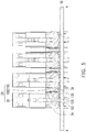
- FIG. 5 is a schematic cross-sectional view taken along the line A-A of FIG. 1 .
- the light guide bar 100 is indicated by bold lines so as to distinguish the locations of the light guide bars 100 and the connectors 30.
- FIG. 5 clearly shows that the light guide bar 100 has an approximately I-shaped cross section, and each light guide bar 100 is clamped between two connectors 30. More specifically, two positioning protrusions 34 on two opposite connector lateral walls 32 of two adjacent connectors 30 enter two positioning recesses 120 on two opposite light guide bar lateral walls 112 of the light guide bar 100, such that the light guide bar 100 and the connectors 30 are fixed by engagement of the protrusions and recesses. It is known from FIG.
- a size of the positioning recess 120 may be slightly greater than a size of the positioning protrusion 34 so as to tolerate an error that may prevent the positioning protrusion 34 from entering the positioning recess 120.
- the positioning protrusion 34 of the connector 30 is still restricted by the four restricting surfaces 122 on the upper, lower, left, and right sides beside the positioning recess 120 of the light guide bar 100 and does not move to a large extent.
- a distance between two opposite light guide bar lateral walls 112 in a region above the positioning recess 120 of the light guide bar 100 is close to a distance between two connector lateral walls 32 of two adjacent connectors 30.
- a width of the light guide bar 100 in the region above the positioning recess 120 is almost close to the gap between two adjacent connectors 30, such that after the light guide bar 100 is inserted into the gap between the two connectors 30, the region above the positioning recess 120 of the light guide bar 100 is clamped by the two connectors 30.
- FIG. 5 clearly shows that the light guide bar 100 is located beside the connectors 30.
- the connectors 30 receive a force in the horizontal direction of FIG. 5 (for example, an expansion card inserted into the connectors 30 may be overly heavy on one side and impose a force on the connectors 30 in the horizontal direction)
- the light guide bar 100 fixed beside the connectors 30 provides a counter force to reduce the possibility of crack of the connectors 30.
- FIG. 6 is a schematic view of a connector of a connector assembly according to another embodiment of the invention.
- FIG. 7 is a schematic cross-sectional view of the connector assembly of FIG. 6 .
- a connector 30a includes a connector body 33 and a connector cover 31 that is disposed closely on the connector body 33 to increase structural strength of the connector body 33.
- the connector body 33 includes a positioning protrusion 34.
- a connector lateral wall 32 is one of the wall surfaces of the connector cover 31.
- the positioning protrusion 34 is exposed and protrudes from the connector cover 31.
- the connector cover 31 further includes a stopper 36 to abut against a light guide bar top surface 115 of the light guide bar body 110 of the light guide bar 100.
- the connector cover 31 covers rising portions on left and right ends of the connector body 33.
- the connector cover 31 has two stoppers 36 on the rising portions on the left and right ends of the connector lateral wall 32.
- each stopper 36 includes an inclined arm.
- the inclined arm is formed by forming a U-shaped opening on the connector cover 31 and then bending a portion surrounded by the U-shaped opening. Because the stopper 36 inclines outward, when the light guide bar 100 moves downward in the direction toward the main board 10 to be assembled between two adjacent connectors 30a, the light guide bar 100 moves downward along the inclined surface of the stopper 36 and at the same time pushes the stopper 36.
- the stopper 36 is slightly deformed toward the plane where the connector lateral wall 32 is located and restores to abut against the light guide bar top surface 115 of the light guide bar body 110 of the light guide bar 100 when the light guide bar 100 has passed. This design further prevents the light guide bar 100 from coming off.
- the stopper 36 may be a protrusion embossed on the connector cover 31.
- the protrusion may be a single protruding dot, a bump, or a combination of a plurality of protruding dots and bumps.
- the form of the stopper 36 is not particularly limited as long as the stopper 36 slightly protrudes outward and abuts against the light guide bar top surface 115 of the light guide bar body 110 of the light guide bar 100 to prevent the light guide bar 100 from moving away from the main board 10.
- the stopper 36 in the form of the inclined arm provides a larger space for the light guide bar 100 to pass, and a length of the inclined arm that protrudes from the connector lateral wall 32 may be greater than a length of the protrusion that protrudes from the connector lateral wall 32.
- the length of the stopper 36 that protrudes from the connector lateral wall 32 needs to be taken into consideration, such that the stopper 36 does not block the light guide bar 100 from passing but is still able to abut against the light guide bar top surface 115 of the light guide bar body 110 of the light guide bar 100 after the light guide bar 100 is in position, so as to prevent the light guide bar 100 from moving away from the main board 10.
- FIG. 8 is a schematic cross-sectional view of a connector assembly according to another embodiment of the invention.
- a main difference between this embodiment and the previous embodiment is that, in the previous embodiment, the stopper 36 that abuts against the light guide bar top surface 115 of the light guide bar body 110 of the light guide bar 100 is located on the connector cover 31; however, in this embodiment, a stopper 36b for abutting against the light guide bar top surface 115 of the light guide bar body 110 of the light guide bar 100 is located on the connector body 33 of a connector 30b.
- the connector cover 31 has an opening 37 at a position corresponding to the stopper 36b of the connector body 33, such that the stopper 36b of the connector body 33 is exposed through the opening 37.
- the stopper 36b may be a bump having an inclined surface, a single protruding dot, or a combination of a plurality of protruding dots, but the form of the stopper 36b of the connector body 33 is not limited to the aforementioned.
- the stopper 36b of this embodiment is able to abut against the light guide bar top surface 115 of the light guide bar body 110 of the light guide bar 100 to keep the light guide bar 100 from moving away from the main board 10.
- a range of the connector body 33 covered by the connector cover 31 may be changed. For example, in an embodiment not shown here, a height of the connector cover 31 is reduced to be lower than the position of the opening 37, such that the stopper 36b is exposed outside the connector cover 31, and formation of the opening 37 on the connector cover 31 is not required.
- the connectors 30a and 30b only include the connector body 33 and do not have the connector cover 31. That is, the connector lateral wall 32 may be one of the wall surfaces of the connector body 33, and the positioning protrusion 34 and the stopper 36b are both located on the connector lateral wall 32 of the connector body 33. This configuration also achieves the function of fixing the light guide bar 100.
- the light guide bar is disposed between two connectors, and the relative positions of the light guide bar and the two connectors are easily fixed by the engagement of the positioning protrusions of the connectors and the positioning recesses of the light guide bar.
- the light guide bar is adapted to be in contact with or close to the light sources on the main board, such that at least a portion of the light emitted by the light sources may enter the light guide bar to generate a strip light between the two connectors for indicating the locations of the connectors in the dark as well as achieving the effect of decoration.
- the connector may crack.
- the light guide bar is disposed beside the connector and applies a counter force on the connector to prevent the connector from being cracked.
Landscapes
- Physics & Mathematics (AREA)
- Engineering & Computer Science (AREA)
- General Engineering & Computer Science (AREA)
- General Physics & Mathematics (AREA)
- Optics & Photonics (AREA)
- Planar Illumination Modules (AREA)
Applications Claiming Priority (2)
| Application Number | Priority Date | Filing Date | Title |
|---|---|---|---|
| TW105113362 | 2016-04-29 | ||
| TW105119043A TWI584532B (zh) | 2016-04-29 | 2016-06-17 | 導光條及連接器集成 |
Publications (2)
| Publication Number | Publication Date |
|---|---|
| EP3240121A1 true EP3240121A1 (de) | 2017-11-01 |
| EP3240121B1 EP3240121B1 (de) | 2019-08-14 |
Family
ID=59367367
Family Applications (1)
| Application Number | Title | Priority Date | Filing Date |
|---|---|---|---|
| EP16202319.6A Active EP3240121B1 (de) | 2016-04-29 | 2016-12-06 | Lichtführungsschiene und verbinderanordnung |
Country Status (3)
| Country | Link |
|---|---|
| US (1) | US10125929B2 (de) |
| EP (1) | EP3240121B1 (de) |
| TW (1) | TWI584532B (de) |
Citations (5)
| Publication number | Priority date | Publication date | Assignee | Title |
|---|---|---|---|---|
| US6368159B1 (en) * | 2000-12-13 | 2002-04-09 | Stewart Connector Systems, Inc. | Light pipe for a modular jack |
| EP1315240A1 (de) * | 2001-11-24 | 2003-05-28 | Murr-Elektronik Gesellschaft mit beschränkter Haftung | Kabelklemme mit optischer Anzeige |
| US7207815B1 (en) * | 2006-04-12 | 2007-04-24 | Lotes Co., Ltd. | Card connector |
| EP2113969A1 (de) * | 2008-04-30 | 2009-11-04 | Tyco Electronics Corporation | Verbinderanordnung mit einer Lichtrohranordnung |
| US20110256769A1 (en) * | 2010-04-19 | 2011-10-20 | Hon Hai Precision Industry Co., Ltd. | Cable assembly having indicating device |
Family Cites Families (9)
| Publication number | Priority date | Publication date | Assignee | Title |
|---|---|---|---|---|
| TWM253928U (en) | 2003-10-31 | 2004-12-21 | Hon Hai Prec Ind Co Ltd | Electrical connector |
| GB0615854D0 (en) | 2006-08-10 | 2006-09-20 | 3M Innovative Properties Co | Light guide for a lighting device |
| GB0813186D0 (en) | 2008-07-18 | 2008-08-27 | 3M Innovative Properties Co | Lighting device comprising a light guide and a support |
| US8348696B2 (en) * | 2009-07-24 | 2013-01-08 | Molex Incorporated | Electrical connector with light pipe |
| TWI422108B (zh) * | 2009-08-12 | 2014-01-01 | Asustek Comp Inc | 具有光學指示之連接模組 |
| EP2317352A1 (de) | 2009-11-03 | 2011-05-04 | 3M Innovative Properties Company | Seitenlichtwellenleiter und Lichtvorrichtung |
| US20120127706A1 (en) * | 2010-11-18 | 2012-05-24 | Jish-Shyan Jiang | Slim led light |
| CN204045807U (zh) * | 2014-07-17 | 2014-12-24 | 富士康(昆山)电脑接插件有限公司 | 电连接器 |
| CN204167613U (zh) * | 2014-10-20 | 2015-02-18 | 温州意华接插件股份有限公司 | 热插拔式接口连接器 |
-
2016
- 2016-06-17 TW TW105119043A patent/TWI584532B/zh not_active IP Right Cessation
- 2016-07-21 US US15/215,604 patent/US10125929B2/en active Active
- 2016-12-06 EP EP16202319.6A patent/EP3240121B1/de active Active
Patent Citations (5)
| Publication number | Priority date | Publication date | Assignee | Title |
|---|---|---|---|---|
| US6368159B1 (en) * | 2000-12-13 | 2002-04-09 | Stewart Connector Systems, Inc. | Light pipe for a modular jack |
| EP1315240A1 (de) * | 2001-11-24 | 2003-05-28 | Murr-Elektronik Gesellschaft mit beschränkter Haftung | Kabelklemme mit optischer Anzeige |
| US7207815B1 (en) * | 2006-04-12 | 2007-04-24 | Lotes Co., Ltd. | Card connector |
| EP2113969A1 (de) * | 2008-04-30 | 2009-11-04 | Tyco Electronics Corporation | Verbinderanordnung mit einer Lichtrohranordnung |
| US20110256769A1 (en) * | 2010-04-19 | 2011-10-20 | Hon Hai Precision Industry Co., Ltd. | Cable assembly having indicating device |
Also Published As
| Publication number | Publication date |
|---|---|
| EP3240121B1 (de) | 2019-08-14 |
| US10125929B2 (en) | 2018-11-13 |
| TW201739119A (zh) | 2017-11-01 |
| US20170314747A1 (en) | 2017-11-02 |
| TWI584532B (zh) | 2017-05-21 |
Similar Documents
| Publication | Publication Date | Title |
|---|---|---|
| US8672713B2 (en) | Connector to be electrically connected to connecting target and to substrate | |
| JP5801116B2 (ja) | コネクタ及びコネクタを備えるモジュール | |
| US10257961B2 (en) | Fixation of heat sink on SFP/XFP cage | |
| KR102153481B1 (ko) | 전기 커넥터 및 그 고정용 만곡 부재 | |
| JP6305086B2 (ja) | 照明装置 | |
| JP2005078832A (ja) | バックライト装置 | |
| JP2018156053A (ja) | 表示装置 | |
| KR20180021895A (ko) | 플러그 커넥터 | |
| JP6698650B2 (ja) | コネクタ、コネクタ搭載基板、照明装置、及び表示装置 | |
| US10125929B2 (en) | Light guide bar and connector assembly | |
| JP4586649B2 (ja) | 光モジュール | |
| WO2024007973A1 (zh) | 氛围灯 | |
| JP2008292962A (ja) | 光コネクタ固定構造および光コネクタ | |
| JP5095156B2 (ja) | 光モジュール | |
| CN105700231A (zh) | 光源模块 | |
| JP6127292B2 (ja) | 接続コネクタ及びコネクタユニット | |
| JP2003068419A (ja) | 基板用コネクタ及び基板用コネクタの端子圧入用治具 | |
| JP2008071823A (ja) | 光モジュール | |
| TWI624702B (zh) | 背板組件及背光模組 | |
| JP6397239B2 (ja) | 電子部品 | |
| JP2008226485A (ja) | バルブソケット | |
| KR200469120Y1 (ko) | 클립타입 지지프레임을 갖는 백라이트유닛 | |
| JP2017183125A (ja) | 光源ユニットおよび照明器具 | |
| JP2005243340A (ja) | 電気部品用ソケット装置 | |
| JP2022056035A (ja) | 照明装置 |
Legal Events
| Date | Code | Title | Description |
|---|---|---|---|
| PUAI | Public reference made under article 153(3) epc to a published international application that has entered the european phase |
Free format text: ORIGINAL CODE: 0009012 |
|
| STAA | Information on the status of an ep patent application or granted ep patent |
Free format text: STATUS: THE APPLICATION HAS BEEN PUBLISHED |
|
| AK | Designated contracting states |
Kind code of ref document: A1 Designated state(s): AL AT BE BG CH CY CZ DE DK EE ES FI FR GB GR HR HU IE IS IT LI LT LU LV MC MK MT NL NO PL PT RO RS SE SI SK SM TR |
|
| AX | Request for extension of the european patent |
Extension state: BA ME |
|
| STAA | Information on the status of an ep patent application or granted ep patent |
Free format text: STATUS: REQUEST FOR EXAMINATION WAS MADE |
|
| 17P | Request for examination filed |
Effective date: 20180309 |
|
| RBV | Designated contracting states (corrected) |
Designated state(s): AL AT BE BG CH CY CZ DE DK EE ES FI FR GB GR HR HU IE IS IT LI LT LU LV MC MK MT NL NO PL PT RO RS SE SI SK SM TR |
|
| STAA | Information on the status of an ep patent application or granted ep patent |
Free format text: STATUS: EXAMINATION IS IN PROGRESS |
|
| 17Q | First examination report despatched |
Effective date: 20180709 |
|
| GRAP | Despatch of communication of intention to grant a patent |
Free format text: ORIGINAL CODE: EPIDOSNIGR1 |
|
| STAA | Information on the status of an ep patent application or granted ep patent |
Free format text: STATUS: GRANT OF PATENT IS INTENDED |
|
| RIC1 | Information provided on ipc code assigned before grant |
Ipc: H01R 13/717 20060101AFI20190306BHEP Ipc: F21V 8/00 20060101ALI20190306BHEP Ipc: G02B 6/00 20060101ALI20190306BHEP |
|
| RIC1 | Information provided on ipc code assigned before grant |
Ipc: F21V 8/00 20060101ALI20190308BHEP Ipc: H01R 13/717 20060101AFI20190308BHEP |
|
| INTG | Intention to grant announced |
Effective date: 20190329 |
|
| GRAS | Grant fee paid |
Free format text: ORIGINAL CODE: EPIDOSNIGR3 |
|
| GRAA | (expected) grant |
Free format text: ORIGINAL CODE: 0009210 |
|
| STAA | Information on the status of an ep patent application or granted ep patent |
Free format text: STATUS: THE PATENT HAS BEEN GRANTED |
|
| AK | Designated contracting states |
Kind code of ref document: B1 Designated state(s): AL AT BE BG CH CY CZ DE DK EE ES FI FR GB GR HR HU IE IS IT LI LT LU LV MC MK MT NL NO PL PT RO RS SE SI SK SM TR |
|
| REG | Reference to a national code |
Ref country code: GB Ref legal event code: FG4D |
|
| REG | Reference to a national code |
Ref country code: CH Ref legal event code: EP Ref country code: AT Ref legal event code: REF Ref document number: 1168131 Country of ref document: AT Kind code of ref document: T Effective date: 20190815 |
|
| REG | Reference to a national code |
Ref country code: IE Ref legal event code: FG4D |
|
| REG | Reference to a national code |
Ref country code: DE Ref legal event code: R096 Ref document number: 602016018524 Country of ref document: DE |
|
| REG | Reference to a national code |
Ref country code: NL Ref legal event code: MP Effective date: 20190814 |
|
| REG | Reference to a national code |
Ref country code: LT Ref legal event code: MG4D |
|
| PG25 | Lapsed in a contracting state [announced via postgrant information from national office to epo] |
Ref country code: FI Free format text: LAPSE BECAUSE OF FAILURE TO SUBMIT A TRANSLATION OF THE DESCRIPTION OR TO PAY THE FEE WITHIN THE PRESCRIBED TIME-LIMIT Effective date: 20190814 Ref country code: LT Free format text: LAPSE BECAUSE OF FAILURE TO SUBMIT A TRANSLATION OF THE DESCRIPTION OR TO PAY THE FEE WITHIN THE PRESCRIBED TIME-LIMIT Effective date: 20190814 Ref country code: HR Free format text: LAPSE BECAUSE OF FAILURE TO SUBMIT A TRANSLATION OF THE DESCRIPTION OR TO PAY THE FEE WITHIN THE PRESCRIBED TIME-LIMIT Effective date: 20190814 Ref country code: SE Free format text: LAPSE BECAUSE OF FAILURE TO SUBMIT A TRANSLATION OF THE DESCRIPTION OR TO PAY THE FEE WITHIN THE PRESCRIBED TIME-LIMIT Effective date: 20190814 Ref country code: PT Free format text: LAPSE BECAUSE OF FAILURE TO SUBMIT A TRANSLATION OF THE DESCRIPTION OR TO PAY THE FEE WITHIN THE PRESCRIBED TIME-LIMIT Effective date: 20191216 Ref country code: NO Free format text: LAPSE BECAUSE OF FAILURE TO SUBMIT A TRANSLATION OF THE DESCRIPTION OR TO PAY THE FEE WITHIN THE PRESCRIBED TIME-LIMIT Effective date: 20191114 Ref country code: NL Free format text: LAPSE BECAUSE OF FAILURE TO SUBMIT A TRANSLATION OF THE DESCRIPTION OR TO PAY THE FEE WITHIN THE PRESCRIBED TIME-LIMIT Effective date: 20190814 Ref country code: BG Free format text: LAPSE BECAUSE OF FAILURE TO SUBMIT A TRANSLATION OF THE DESCRIPTION OR TO PAY THE FEE WITHIN THE PRESCRIBED TIME-LIMIT Effective date: 20191114 |
|
| REG | Reference to a national code |
Ref country code: AT Ref legal event code: MK05 Ref document number: 1168131 Country of ref document: AT Kind code of ref document: T Effective date: 20190814 |
|
| PG25 | Lapsed in a contracting state [announced via postgrant information from national office to epo] |
Ref country code: LV Free format text: LAPSE BECAUSE OF FAILURE TO SUBMIT A TRANSLATION OF THE DESCRIPTION OR TO PAY THE FEE WITHIN THE PRESCRIBED TIME-LIMIT Effective date: 20190814 Ref country code: AL Free format text: LAPSE BECAUSE OF FAILURE TO SUBMIT A TRANSLATION OF THE DESCRIPTION OR TO PAY THE FEE WITHIN THE PRESCRIBED TIME-LIMIT Effective date: 20190814 Ref country code: ES Free format text: LAPSE BECAUSE OF FAILURE TO SUBMIT A TRANSLATION OF THE DESCRIPTION OR TO PAY THE FEE WITHIN THE PRESCRIBED TIME-LIMIT Effective date: 20190814 Ref country code: RS Free format text: LAPSE BECAUSE OF FAILURE TO SUBMIT A TRANSLATION OF THE DESCRIPTION OR TO PAY THE FEE WITHIN THE PRESCRIBED TIME-LIMIT Effective date: 20190814 Ref country code: GR Free format text: LAPSE BECAUSE OF FAILURE TO SUBMIT A TRANSLATION OF THE DESCRIPTION OR TO PAY THE FEE WITHIN THE PRESCRIBED TIME-LIMIT Effective date: 20191115 Ref country code: IS Free format text: LAPSE BECAUSE OF FAILURE TO SUBMIT A TRANSLATION OF THE DESCRIPTION OR TO PAY THE FEE WITHIN THE PRESCRIBED TIME-LIMIT Effective date: 20191214 |
|
| PG25 | Lapsed in a contracting state [announced via postgrant information from national office to epo] |
Ref country code: TR Free format text: LAPSE BECAUSE OF FAILURE TO SUBMIT A TRANSLATION OF THE DESCRIPTION OR TO PAY THE FEE WITHIN THE PRESCRIBED TIME-LIMIT Effective date: 20190814 |
|
| PG25 | Lapsed in a contracting state [announced via postgrant information from national office to epo] |
Ref country code: EE Free format text: LAPSE BECAUSE OF FAILURE TO SUBMIT A TRANSLATION OF THE DESCRIPTION OR TO PAY THE FEE WITHIN THE PRESCRIBED TIME-LIMIT Effective date: 20190814 Ref country code: PL Free format text: LAPSE BECAUSE OF FAILURE TO SUBMIT A TRANSLATION OF THE DESCRIPTION OR TO PAY THE FEE WITHIN THE PRESCRIBED TIME-LIMIT Effective date: 20190814 Ref country code: AT Free format text: LAPSE BECAUSE OF FAILURE TO SUBMIT A TRANSLATION OF THE DESCRIPTION OR TO PAY THE FEE WITHIN THE PRESCRIBED TIME-LIMIT Effective date: 20190814 Ref country code: RO Free format text: LAPSE BECAUSE OF FAILURE TO SUBMIT A TRANSLATION OF THE DESCRIPTION OR TO PAY THE FEE WITHIN THE PRESCRIBED TIME-LIMIT Effective date: 20190814 Ref country code: IT Free format text: LAPSE BECAUSE OF FAILURE TO SUBMIT A TRANSLATION OF THE DESCRIPTION OR TO PAY THE FEE WITHIN THE PRESCRIBED TIME-LIMIT Effective date: 20190814 Ref country code: DK Free format text: LAPSE BECAUSE OF FAILURE TO SUBMIT A TRANSLATION OF THE DESCRIPTION OR TO PAY THE FEE WITHIN THE PRESCRIBED TIME-LIMIT Effective date: 20190814 |
|
| PG25 | Lapsed in a contracting state [announced via postgrant information from national office to epo] |
Ref country code: SK Free format text: LAPSE BECAUSE OF FAILURE TO SUBMIT A TRANSLATION OF THE DESCRIPTION OR TO PAY THE FEE WITHIN THE PRESCRIBED TIME-LIMIT Effective date: 20190814 Ref country code: IS Free format text: LAPSE BECAUSE OF FAILURE TO SUBMIT A TRANSLATION OF THE DESCRIPTION OR TO PAY THE FEE WITHIN THE PRESCRIBED TIME-LIMIT Effective date: 20200224 Ref country code: SM Free format text: LAPSE BECAUSE OF FAILURE TO SUBMIT A TRANSLATION OF THE DESCRIPTION OR TO PAY THE FEE WITHIN THE PRESCRIBED TIME-LIMIT Effective date: 20190814 Ref country code: CZ Free format text: LAPSE BECAUSE OF FAILURE TO SUBMIT A TRANSLATION OF THE DESCRIPTION OR TO PAY THE FEE WITHIN THE PRESCRIBED TIME-LIMIT Effective date: 20190814 |
|
| REG | Reference to a national code |
Ref country code: DE Ref legal event code: R097 Ref document number: 602016018524 Country of ref document: DE |
|
| PLBE | No opposition filed within time limit |
Free format text: ORIGINAL CODE: 0009261 |
|
| STAA | Information on the status of an ep patent application or granted ep patent |
Free format text: STATUS: NO OPPOSITION FILED WITHIN TIME LIMIT |
|
| PG2D | Information on lapse in contracting state deleted |
Ref country code: IS |
|
| REG | Reference to a national code |
Ref country code: CH Ref legal event code: PL |
|
| 26N | No opposition filed |
Effective date: 20200603 |
|
| REG | Reference to a national code |
Ref country code: BE Ref legal event code: MM Effective date: 20191231 |
|
| PG25 | Lapsed in a contracting state [announced via postgrant information from national office to epo] |
Ref country code: SI Free format text: LAPSE BECAUSE OF FAILURE TO SUBMIT A TRANSLATION OF THE DESCRIPTION OR TO PAY THE FEE WITHIN THE PRESCRIBED TIME-LIMIT Effective date: 20190814 Ref country code: MC Free format text: LAPSE BECAUSE OF FAILURE TO SUBMIT A TRANSLATION OF THE DESCRIPTION OR TO PAY THE FEE WITHIN THE PRESCRIBED TIME-LIMIT Effective date: 20190814 |
|
| PG25 | Lapsed in a contracting state [announced via postgrant information from national office to epo] |
Ref country code: IE Free format text: LAPSE BECAUSE OF NON-PAYMENT OF DUE FEES Effective date: 20191206 Ref country code: LU Free format text: LAPSE BECAUSE OF NON-PAYMENT OF DUE FEES Effective date: 20191206 |
|
| PG25 | Lapsed in a contracting state [announced via postgrant information from national office to epo] |
Ref country code: CH Free format text: LAPSE BECAUSE OF NON-PAYMENT OF DUE FEES Effective date: 20191231 Ref country code: BE Free format text: LAPSE BECAUSE OF NON-PAYMENT OF DUE FEES Effective date: 20191231 Ref country code: LI Free format text: LAPSE BECAUSE OF NON-PAYMENT OF DUE FEES Effective date: 20191231 |
|
| PG25 | Lapsed in a contracting state [announced via postgrant information from national office to epo] |
Ref country code: CY Free format text: LAPSE BECAUSE OF FAILURE TO SUBMIT A TRANSLATION OF THE DESCRIPTION OR TO PAY THE FEE WITHIN THE PRESCRIBED TIME-LIMIT Effective date: 20190814 |
|
| PG25 | Lapsed in a contracting state [announced via postgrant information from national office to epo] |
Ref country code: HU Free format text: LAPSE BECAUSE OF FAILURE TO SUBMIT A TRANSLATION OF THE DESCRIPTION OR TO PAY THE FEE WITHIN THE PRESCRIBED TIME-LIMIT; INVALID AB INITIO Effective date: 20161206 Ref country code: MT Free format text: LAPSE BECAUSE OF FAILURE TO SUBMIT A TRANSLATION OF THE DESCRIPTION OR TO PAY THE FEE WITHIN THE PRESCRIBED TIME-LIMIT Effective date: 20190814 |
|
| PG25 | Lapsed in a contracting state [announced via postgrant information from national office to epo] |
Ref country code: MK Free format text: LAPSE BECAUSE OF FAILURE TO SUBMIT A TRANSLATION OF THE DESCRIPTION OR TO PAY THE FEE WITHIN THE PRESCRIBED TIME-LIMIT Effective date: 20190814 |
|
| PGFP | Annual fee paid to national office [announced via postgrant information from national office to epo] |
Ref country code: FR Payment date: 20221010 Year of fee payment: 7 |
|
| PGFP | Annual fee paid to national office [announced via postgrant information from national office to epo] |
Ref country code: GB Payment date: 20221013 Year of fee payment: 7 Ref country code: DE Payment date: 20220622 Year of fee payment: 7 |