EP3240094B1 - Electrolyte solution for secondary batteries, and secondary battery comprising the same - Google Patents
Electrolyte solution for secondary batteries, and secondary battery comprising the same Download PDFInfo
- Publication number
- EP3240094B1 EP3240094B1 EP15872474.0A EP15872474A EP3240094B1 EP 3240094 B1 EP3240094 B1 EP 3240094B1 EP 15872474 A EP15872474 A EP 15872474A EP 3240094 B1 EP3240094 B1 EP 3240094B1
- Authority
- EP
- European Patent Office
- Prior art keywords
- liquid electrolyte
- secondary battery
- lithium
- positive electrode
- liquid
- Prior art date
- Legal status (The legal status is an assumption and is not a legal conclusion. Google has not performed a legal analysis and makes no representation as to the accuracy of the status listed.)
- Active
Links
- 239000008151 electrolyte solution Substances 0.000 title description 7
- 239000011244 liquid electrolyte Substances 0.000 claims description 69
- 239000002608 ionic liquid Substances 0.000 claims description 40
- 229910003002 lithium salt Inorganic materials 0.000 claims description 28
- 159000000002 lithium salts Chemical class 0.000 claims description 28
- -1 lithium tetrafluoroborate Chemical compound 0.000 claims description 24
- 229910052744 lithium Inorganic materials 0.000 claims description 19
- WHXSMMKQMYFTQS-UHFFFAOYSA-N Lithium Chemical compound [Li] WHXSMMKQMYFTQS-UHFFFAOYSA-N 0.000 claims description 18
- 239000007774 positive electrode material Substances 0.000 claims description 9
- 239000007773 negative electrode material Substances 0.000 claims description 8
- 125000002496 methyl group Chemical group [H]C([H])([H])* 0.000 claims description 7
- 229910001496 lithium tetrafluoroborate Inorganic materials 0.000 claims description 6
- VDVLPSWVDYJFRW-UHFFFAOYSA-N lithium;bis(fluorosulfonyl)azanide Chemical compound [Li+].FS(=O)(=O)[N-]S(F)(=O)=O VDVLPSWVDYJFRW-UHFFFAOYSA-N 0.000 claims description 6
- 239000003960 organic solvent Substances 0.000 claims description 6
- 125000000217 alkyl group Chemical group 0.000 claims description 5
- 125000004432 carbon atom Chemical group C* 0.000 claims description 4
- 239000002131 composite material Substances 0.000 claims description 4
- 125000001495 ethyl group Chemical group [H]C([H])([H])C([H])([H])* 0.000 claims description 4
- QSZMZKBZAYQGRS-UHFFFAOYSA-N lithium;bis(trifluoromethylsulfonyl)azanide Chemical compound [Li+].FC(F)(F)S(=O)(=O)[N-]S(=O)(=O)C(F)(F)F QSZMZKBZAYQGRS-UHFFFAOYSA-N 0.000 claims description 4
- 230000000052 comparative effect Effects 0.000 description 27
- 239000010410 layer Substances 0.000 description 22
- SECXISVLQFMRJM-UHFFFAOYSA-N N-Methylpyrrolidone Chemical compound CN1CCCC1=O SECXISVLQFMRJM-UHFFFAOYSA-N 0.000 description 20
- VZSRBBMJRBPUNF-UHFFFAOYSA-N 2-(2,3-dihydro-1H-inden-2-ylamino)-N-[3-oxo-3-(2,4,6,7-tetrahydrotriazolo[4,5-c]pyridin-5-yl)propyl]pyrimidine-5-carboxamide Chemical compound C1C(CC2=CC=CC=C12)NC1=NC=C(C=N1)C(=O)NCCC(N1CC2=C(CC1)NN=N2)=O VZSRBBMJRBPUNF-UHFFFAOYSA-N 0.000 description 16
- OKTJSMMVPCPJKN-UHFFFAOYSA-N Carbon Chemical compound [C] OKTJSMMVPCPJKN-UHFFFAOYSA-N 0.000 description 14
- 239000011888 foil Substances 0.000 description 13
- 239000000243 solution Substances 0.000 description 13
- 239000002904 solvent Substances 0.000 description 12
- 230000015572 biosynthetic process Effects 0.000 description 11
- 238000003786 synthesis reaction Methods 0.000 description 11
- 229910052782 aluminium Inorganic materials 0.000 description 10
- XAGFODPZIPBFFR-UHFFFAOYSA-N aluminium Chemical compound [Al] XAGFODPZIPBFFR-UHFFFAOYSA-N 0.000 description 10
- 239000000463 material Substances 0.000 description 10
- 239000000126 substance Substances 0.000 description 9
- YLZOPXRUQYQQID-UHFFFAOYSA-N 3-(2,4,6,7-tetrahydrotriazolo[4,5-c]pyridin-5-yl)-1-[4-[2-[[3-(trifluoromethoxy)phenyl]methylamino]pyrimidin-5-yl]piperazin-1-yl]propan-1-one Chemical compound N1N=NC=2CN(CCC=21)CCC(=O)N1CCN(CC1)C=1C=NC(=NC=1)NCC1=CC(=CC=C1)OC(F)(F)F YLZOPXRUQYQQID-UHFFFAOYSA-N 0.000 description 8
- AFCARXCZXQIEQB-UHFFFAOYSA-N N-[3-oxo-3-(2,4,6,7-tetrahydrotriazolo[4,5-c]pyridin-5-yl)propyl]-2-[[3-(trifluoromethoxy)phenyl]methylamino]pyrimidine-5-carboxamide Chemical compound O=C(CCNC(=O)C=1C=NC(=NC=1)NCC1=CC(=CC=C1)OC(F)(F)F)N1CC2=C(CC1)NN=N2 AFCARXCZXQIEQB-UHFFFAOYSA-N 0.000 description 8
- 238000004519 manufacturing process Methods 0.000 description 8
- HBBGRARXTFLTSG-UHFFFAOYSA-N Lithium ion Chemical compound [Li+] HBBGRARXTFLTSG-UHFFFAOYSA-N 0.000 description 7
- 239000011248 coating agent Substances 0.000 description 7
- 238000000576 coating method Methods 0.000 description 7
- 229910000625 lithium cobalt oxide Inorganic materials 0.000 description 7
- 229910001416 lithium ion Inorganic materials 0.000 description 7
- 238000000034 method Methods 0.000 description 7
- XLYOFNOQVPJJNP-UHFFFAOYSA-N water Substances O XLYOFNOQVPJJNP-UHFFFAOYSA-N 0.000 description 7
- 239000002033 PVDF binder Substances 0.000 description 6
- 150000001768 cations Chemical class 0.000 description 6
- NEHMKBQYUWJMIP-UHFFFAOYSA-N chloromethane Chemical compound ClC NEHMKBQYUWJMIP-UHFFFAOYSA-N 0.000 description 6
- 239000008367 deionised water Substances 0.000 description 6
- 229910021641 deionized water Inorganic materials 0.000 description 6
- 239000003792 electrolyte Substances 0.000 description 6
- 238000005259 measurement Methods 0.000 description 6
- 229920002981 polyvinylidene fluoride Polymers 0.000 description 6
- 238000003756 stirring Methods 0.000 description 6
- 150000001450 anions Chemical class 0.000 description 5
- 239000011230 binding agent Substances 0.000 description 5
- 239000003990 capacitor Substances 0.000 description 5
- 238000006243 chemical reaction Methods 0.000 description 5
- 230000001351 cycling effect Effects 0.000 description 5
- 238000007599 discharging Methods 0.000 description 5
- 239000007788 liquid Substances 0.000 description 5
- BFZPBUKRYWOWDV-UHFFFAOYSA-N lithium;oxido(oxo)cobalt Chemical compound [Li+].[O-][Co]=O BFZPBUKRYWOWDV-UHFFFAOYSA-N 0.000 description 5
- 238000002156 mixing Methods 0.000 description 5
- 150000003839 salts Chemical class 0.000 description 5
- WYURNTSHIVDZCO-UHFFFAOYSA-N Tetrahydrofuran Chemical compound C1CCOC1 WYURNTSHIVDZCO-UHFFFAOYSA-N 0.000 description 4
- 150000001875 compounds Chemical class 0.000 description 4
- 239000013078 crystal Substances 0.000 description 4
- 229940021013 electrolyte solution Drugs 0.000 description 4
- 239000007789 gas Substances 0.000 description 4
- PXHVJJICTQNCMI-UHFFFAOYSA-N nickel Substances [Ni] PXHVJJICTQNCMI-UHFFFAOYSA-N 0.000 description 4
- 229910052757 nitrogen Inorganic materials 0.000 description 4
- 238000000425 proton nuclear magnetic resonance spectrum Methods 0.000 description 4
- 238000012360 testing method Methods 0.000 description 4
- WEVYAHXRMPXWCK-UHFFFAOYSA-N Acetonitrile Chemical compound CC#N WEVYAHXRMPXWCK-UHFFFAOYSA-N 0.000 description 3
- ZMXDDKWLCZADIW-UHFFFAOYSA-N N,N-Dimethylformamide Chemical compound CN(C)C=O ZMXDDKWLCZADIW-UHFFFAOYSA-N 0.000 description 3
- NIPNSKYNPDTRPC-UHFFFAOYSA-N N-[2-oxo-2-(2,4,6,7-tetrahydrotriazolo[4,5-c]pyridin-5-yl)ethyl]-2-[[3-(trifluoromethoxy)phenyl]methylamino]pyrimidine-5-carboxamide Chemical compound O=C(CNC(=O)C=1C=NC(=NC=1)NCC1=CC(=CC=C1)OC(F)(F)F)N1CC2=C(CC1)NN=N2 NIPNSKYNPDTRPC-UHFFFAOYSA-N 0.000 description 3
- RWRDLPDLKQPQOW-UHFFFAOYSA-N Pyrrolidine Chemical compound C1CCNC1 RWRDLPDLKQPQOW-UHFFFAOYSA-N 0.000 description 3
- RTAQQCXQSZGOHL-UHFFFAOYSA-N Titanium Chemical compound [Ti] RTAQQCXQSZGOHL-UHFFFAOYSA-N 0.000 description 3
- YXFVVABEGXRONW-UHFFFAOYSA-N Toluene Chemical compound CC1=CC=CC=C1 YXFVVABEGXRONW-UHFFFAOYSA-N 0.000 description 3
- 239000003575 carbonaceous material Substances 0.000 description 3
- 239000002482 conductive additive Substances 0.000 description 3
- 239000004020 conductor Substances 0.000 description 3
- 230000006866 deterioration Effects 0.000 description 3
- 238000001035 drying Methods 0.000 description 3
- 150000002500 ions Chemical class 0.000 description 3
- 229940050176 methyl chloride Drugs 0.000 description 3
- 125000004433 nitrogen atom Chemical group N* 0.000 description 3
- 229920000642 polymer Polymers 0.000 description 3
- 229920000098 polyolefin Polymers 0.000 description 3
- 239000011541 reaction mixture Substances 0.000 description 3
- 239000007787 solid Substances 0.000 description 3
- 239000013076 target substance Substances 0.000 description 3
- 239000010936 titanium Substances 0.000 description 3
- ZOSPVHQYAGHQPI-UHFFFAOYSA-M 1-(2-methoxyethyl)-1-methylpyrrolidin-1-ium chloride Chemical compound [Cl-].COCC[N+]1(CCCC1)C ZOSPVHQYAGHQPI-UHFFFAOYSA-M 0.000 description 2
- ZKLQIVPPHFQZOK-UHFFFAOYSA-N 1-(2-methoxyethyl)pyrrolidine Chemical compound COCCN1CCCC1 ZKLQIVPPHFQZOK-UHFFFAOYSA-N 0.000 description 2
- GTHWJSPEAAGERR-UHFFFAOYSA-M 1-(methoxymethyl)-1-methylpyrrolidin-1-ium;chloride Chemical compound [Cl-].COC[N+]1(C)CCCC1 GTHWJSPEAAGERR-UHFFFAOYSA-M 0.000 description 2
- YEJRWHAVMIAJKC-UHFFFAOYSA-N 4-Butyrolactone Chemical compound O=C1CCCO1 YEJRWHAVMIAJKC-UHFFFAOYSA-N 0.000 description 2
- 229910000838 Al alloy Inorganic materials 0.000 description 2
- IJGRMHOSHXDMSA-UHFFFAOYSA-N Atomic nitrogen Chemical compound N#N IJGRMHOSHXDMSA-UHFFFAOYSA-N 0.000 description 2
- VEXZGXHMUGYJMC-UHFFFAOYSA-M Chloride anion Chemical compound [Cl-] VEXZGXHMUGYJMC-UHFFFAOYSA-M 0.000 description 2
- XTHFKEDIFFGKHM-UHFFFAOYSA-N Dimethoxyethane Chemical compound COCCOC XTHFKEDIFFGKHM-UHFFFAOYSA-N 0.000 description 2
- ATHHXGZTWNVVOU-UHFFFAOYSA-N N-methylformamide Chemical compound CNC=O ATHHXGZTWNVVOU-UHFFFAOYSA-N 0.000 description 2
- KDLHZDBZIXYQEI-UHFFFAOYSA-N Palladium Chemical compound [Pd] KDLHZDBZIXYQEI-UHFFFAOYSA-N 0.000 description 2
- 239000006230 acetylene black Substances 0.000 description 2
- 230000004913 activation Effects 0.000 description 2
- 239000011149 active material Substances 0.000 description 2
- 239000000654 additive Substances 0.000 description 2
- 230000000996 additive effect Effects 0.000 description 2
- 239000003463 adsorbent Substances 0.000 description 2
- 239000003125 aqueous solvent Substances 0.000 description 2
- QVGXLLKOCUKJST-UHFFFAOYSA-N atomic oxygen Chemical compound [O] QVGXLLKOCUKJST-UHFFFAOYSA-N 0.000 description 2
- NVIANCROYQGROD-UHFFFAOYSA-N bis(fluorosulfonyl)azanide Chemical compound FS(=O)(=O)[N-]S(F)(=O)=O NVIANCROYQGROD-UHFFFAOYSA-N 0.000 description 2
- HBTKRUXLKWRXSK-UHFFFAOYSA-N bis(fluorosulfonyl)azanide 1-(2-methoxyethyl)-1-methylpyrrolidin-1-ium Chemical compound FS(=O)(=O)[N-]S(F)(=O)=O.COCC[N+]1(C)CCCC1 HBTKRUXLKWRXSK-UHFFFAOYSA-N 0.000 description 2
- 229910052799 carbon Inorganic materials 0.000 description 2
- 239000006255 coating slurry Substances 0.000 description 2
- 229920001577 copolymer Polymers 0.000 description 2
- 125000004122 cyclic group Chemical group 0.000 description 2
- 230000003247 decreasing effect Effects 0.000 description 2
- 125000001033 ether group Chemical group 0.000 description 2
- 239000011521 glass Substances 0.000 description 2
- 239000004615 ingredient Substances 0.000 description 2
- AMXOYNBUYSYVKV-UHFFFAOYSA-M lithium bromide Chemical compound [Li+].[Br-] AMXOYNBUYSYVKV-UHFFFAOYSA-M 0.000 description 2
- HSZCZNFXUDYRKD-UHFFFAOYSA-M lithium iodide Chemical compound [Li+].[I-] HSZCZNFXUDYRKD-UHFFFAOYSA-M 0.000 description 2
- IIPYXGDZVMZOAP-UHFFFAOYSA-N lithium nitrate Chemical compound [Li+].[O-][N+]([O-])=O IIPYXGDZVMZOAP-UHFFFAOYSA-N 0.000 description 2
- FUJCRWPEOMXPAD-UHFFFAOYSA-N lithium oxide Chemical class [Li+].[Li+].[O-2] FUJCRWPEOMXPAD-UHFFFAOYSA-N 0.000 description 2
- 229910001947 lithium oxide Inorganic materials 0.000 description 2
- 230000014759 maintenance of location Effects 0.000 description 2
- 239000012528 membrane Substances 0.000 description 2
- 239000000203 mixture Substances 0.000 description 2
- KTQDYGVEEFGIIL-UHFFFAOYSA-N n-fluorosulfonylsulfamoyl fluoride Chemical compound FS(=O)(=O)NS(F)(=O)=O KTQDYGVEEFGIIL-UHFFFAOYSA-N 0.000 description 2
- 239000011356 non-aqueous organic solvent Substances 0.000 description 2
- 239000012044 organic layer Substances 0.000 description 2
- 229910052760 oxygen Inorganic materials 0.000 description 2
- 239000001301 oxygen Substances 0.000 description 2
- BASFCYQUMIYNBI-UHFFFAOYSA-N platinum Chemical compound [Pt] BASFCYQUMIYNBI-UHFFFAOYSA-N 0.000 description 2
- MHEBVKPOSBNNAC-UHFFFAOYSA-N potassium;bis(fluorosulfonyl)azanide Chemical compound [K+].FS(=O)(=O)[N-]S(F)(=O)=O MHEBVKPOSBNNAC-UHFFFAOYSA-N 0.000 description 2
- RUOJZAUFBMNUDX-UHFFFAOYSA-N propylene carbonate Chemical compound CC1COC(=O)O1 RUOJZAUFBMNUDX-UHFFFAOYSA-N 0.000 description 2
- 150000003242 quaternary ammonium salts Chemical class 0.000 description 2
- 239000002002 slurry Substances 0.000 description 2
- 239000007858 starting material Substances 0.000 description 2
- YLQBMQCUIZJEEH-UHFFFAOYSA-N tetrahydrofuran Natural products C=1C=COC=1 YLQBMQCUIZJEEH-UHFFFAOYSA-N 0.000 description 2
- 229910052719 titanium Inorganic materials 0.000 description 2
- 238000003466 welding Methods 0.000 description 2
- ZZXUZKXVROWEIF-UHFFFAOYSA-N 1,2-butylene carbonate Chemical compound CCC1COC(=O)O1 ZZXUZKXVROWEIF-UHFFFAOYSA-N 0.000 description 1
- LZDKZFUFMNSQCJ-UHFFFAOYSA-N 1,2-diethoxyethane Chemical compound CCOCCOCC LZDKZFUFMNSQCJ-UHFFFAOYSA-N 0.000 description 1
- CYSGHNMQYZDMIA-UHFFFAOYSA-N 1,3-Dimethyl-2-imidazolidinon Chemical compound CN1CCN(C)C1=O CYSGHNMQYZDMIA-UHFFFAOYSA-N 0.000 description 1
- WNXJIVFYUVYPPR-UHFFFAOYSA-N 1,3-dioxolane Chemical compound C1COCO1 WNXJIVFYUVYPPR-UHFFFAOYSA-N 0.000 description 1
- KZVBBTZJMSWGTK-UHFFFAOYSA-N 1-[2-(2-butoxyethoxy)ethoxy]butane Chemical compound CCCCOCCOCCOCCCC KZVBBTZJMSWGTK-UHFFFAOYSA-N 0.000 description 1
- JRRDISHSXWGFRF-UHFFFAOYSA-N 1-[2-(2-ethoxyethoxy)ethoxy]-2-methoxyethane Chemical compound CCOCCOCCOCCOC JRRDISHSXWGFRF-UHFFFAOYSA-N 0.000 description 1
- YZWVMKLQNYGKLJ-UHFFFAOYSA-N 1-[2-[2-(2-ethoxyethoxy)ethoxy]ethoxy]-2-methoxyethane Chemical compound CCOCCOCCOCCOCCOC YZWVMKLQNYGKLJ-UHFFFAOYSA-N 0.000 description 1
- DURPTKYDGMDSBL-UHFFFAOYSA-N 1-butoxybutane Chemical compound CCCCOCCCC DURPTKYDGMDSBL-UHFFFAOYSA-N 0.000 description 1
- XTIGGAHUZJWQMD-UHFFFAOYSA-N 1-chloro-2-methoxyethane Chemical compound COCCCl XTIGGAHUZJWQMD-UHFFFAOYSA-N 0.000 description 1
- RRQYJINTUHWNHW-UHFFFAOYSA-N 1-ethoxy-2-(2-ethoxyethoxy)ethane Chemical compound CCOCCOCCOCC RRQYJINTUHWNHW-UHFFFAOYSA-N 0.000 description 1
- AVFZOVWCLRSYKC-UHFFFAOYSA-N 1-methylpyrrolidine Chemical compound CN1CCCC1 AVFZOVWCLRSYKC-UHFFFAOYSA-N 0.000 description 1
- 238000005160 1H NMR spectroscopy Methods 0.000 description 1
- RNFJDJUURJAICM-UHFFFAOYSA-N 2,2,4,4,6,6-hexaphenoxy-1,3,5-triaza-2$l^{5},4$l^{5},6$l^{5}-triphosphacyclohexa-1,3,5-triene Chemical compound N=1P(OC=2C=CC=CC=2)(OC=2C=CC=CC=2)=NP(OC=2C=CC=CC=2)(OC=2C=CC=CC=2)=NP=1(OC=1C=CC=CC=1)OC1=CC=CC=C1 RNFJDJUURJAICM-UHFFFAOYSA-N 0.000 description 1
- OAYXUHPQHDHDDZ-UHFFFAOYSA-N 2-(2-butoxyethoxy)ethanol Chemical compound CCCCOCCOCCO OAYXUHPQHDHDDZ-UHFFFAOYSA-N 0.000 description 1
- POAOYUHQDCAZBD-UHFFFAOYSA-N 2-butoxyethanol Chemical compound CCCCOCCO POAOYUHQDCAZBD-UHFFFAOYSA-N 0.000 description 1
- ZNQVEEAIQZEUHB-UHFFFAOYSA-N 2-ethoxyethanol Chemical compound CCOCCO ZNQVEEAIQZEUHB-UHFFFAOYSA-N 0.000 description 1
- KXGFMDJXCMQABM-UHFFFAOYSA-N 2-methoxy-6-methylphenol Chemical compound [CH]OC1=CC=CC([CH])=C1O KXGFMDJXCMQABM-UHFFFAOYSA-N 0.000 description 1
- JWUJQDFVADABEY-UHFFFAOYSA-N 2-methyltetrahydrofuran Chemical compound CC1CCCO1 JWUJQDFVADABEY-UHFFFAOYSA-N 0.000 description 1
- BELGHMWMXFCZTP-UHFFFAOYSA-N 3-ethyl-1,3-oxazolidin-2-one Chemical compound CCN1CCOC1=O BELGHMWMXFCZTP-UHFFFAOYSA-N 0.000 description 1
- VWIIJDNADIEEDB-UHFFFAOYSA-N 3-methyl-1,3-oxazolidin-2-one Chemical compound CN1CCOC1=O VWIIJDNADIEEDB-UHFFFAOYSA-N 0.000 description 1
- GDKSTFXHMBGCPG-UHFFFAOYSA-N 4,4-dimethyl-1,3-dioxane Chemical compound CC1(C)CCOCO1 GDKSTFXHMBGCPG-UHFFFAOYSA-N 0.000 description 1
- JZVUAOCDNFNSGQ-UHFFFAOYSA-N 7-methoxy-2-phenyl-1h-quinolin-4-one Chemical compound N=1C2=CC(OC)=CC=C2C(O)=CC=1C1=CC=CC=C1 JZVUAOCDNFNSGQ-UHFFFAOYSA-N 0.000 description 1
- QGZKDVFQNNGYKY-UHFFFAOYSA-O Ammonium Chemical compound [NH4+] QGZKDVFQNNGYKY-UHFFFAOYSA-O 0.000 description 1
- BTBUEUYNUDRHOZ-UHFFFAOYSA-N Borate Chemical compound [O-]B([O-])[O-] BTBUEUYNUDRHOZ-UHFFFAOYSA-N 0.000 description 1
- CPELXLSAUQHCOX-UHFFFAOYSA-M Bromide Chemical compound [Br-] CPELXLSAUQHCOX-UHFFFAOYSA-M 0.000 description 1
- OYPRJOBELJOOCE-UHFFFAOYSA-N Calcium Chemical compound [Ca] OYPRJOBELJOOCE-UHFFFAOYSA-N 0.000 description 1
- 229920000049 Carbon (fiber) Polymers 0.000 description 1
- 229920002134 Carboxymethyl cellulose Polymers 0.000 description 1
- XJUZRXYOEPSWMB-UHFFFAOYSA-N Chloromethyl methyl ether Chemical compound COCCl XJUZRXYOEPSWMB-UHFFFAOYSA-N 0.000 description 1
- 235000013162 Cocos nucifera Nutrition 0.000 description 1
- 244000060011 Cocos nucifera Species 0.000 description 1
- RYGMFSIKBFXOCR-UHFFFAOYSA-N Copper Chemical compound [Cu] RYGMFSIKBFXOCR-UHFFFAOYSA-N 0.000 description 1
- 229910000881 Cu alloy Inorganic materials 0.000 description 1
- OIFBSDVPJOWBCH-UHFFFAOYSA-N Diethyl carbonate Chemical compound CCOC(=O)OCC OIFBSDVPJOWBCH-UHFFFAOYSA-N 0.000 description 1
- IAZDPXIOMUYVGZ-WFGJKAKNSA-N Dimethyl sulfoxide Chemical compound [2H]C([2H])([2H])S(=O)C([2H])([2H])[2H] IAZDPXIOMUYVGZ-WFGJKAKNSA-N 0.000 description 1
- 229920002943 EPDM rubber Polymers 0.000 description 1
- KMTRUDSVKNLOMY-UHFFFAOYSA-N Ethylene carbonate Chemical compound O=C1OCCO1 KMTRUDSVKNLOMY-UHFFFAOYSA-N 0.000 description 1
- LYKZLSOWKOVLKF-UHFFFAOYSA-N FS(=O)(=O)[N-]S(=O)(=O)F.COC[N+]1(CCCC1)C Chemical compound FS(=O)(=O)[N-]S(=O)(=O)F.COC[N+]1(CCCC1)C LYKZLSOWKOVLKF-UHFFFAOYSA-N 0.000 description 1
- CWYNVVGOOAEACU-UHFFFAOYSA-N Fe2+ Chemical compound [Fe+2] CWYNVVGOOAEACU-UHFFFAOYSA-N 0.000 description 1
- DGAQECJNVWCQMB-PUAWFVPOSA-M Ilexoside XXIX Chemical compound C[C@@H]1CC[C@@]2(CC[C@@]3(C(=CC[C@H]4[C@]3(CC[C@@H]5[C@@]4(CC[C@@H](C5(C)C)OS(=O)(=O)[O-])C)C)[C@@H]2[C@]1(C)O)C)C(=O)O[C@H]6[C@@H]([C@H]([C@@H]([C@H](O6)CO)O)O)O.[Na+] DGAQECJNVWCQMB-PUAWFVPOSA-M 0.000 description 1
- 229910000733 Li alloy Inorganic materials 0.000 description 1
- 229910002983 Li2MnO3 Inorganic materials 0.000 description 1
- 229910001305 LiMPO4 Inorganic materials 0.000 description 1
- 229910002993 LiMnO2 Inorganic materials 0.000 description 1
- 229910015915 LiNi0.8Co0.2O2 Inorganic materials 0.000 description 1
- 229910003005 LiNiO2 Inorganic materials 0.000 description 1
- 229910013100 LiNix Inorganic materials 0.000 description 1
- 229910001290 LiPF6 Inorganic materials 0.000 description 1
- WAEMQWOKJMHJLA-UHFFFAOYSA-N Manganese(2+) Chemical compound [Mn+2] WAEMQWOKJMHJLA-UHFFFAOYSA-N 0.000 description 1
- AHVYPIQETPWLSZ-UHFFFAOYSA-N N-methyl-pyrrolidine Natural products CN1CC=CC1 AHVYPIQETPWLSZ-UHFFFAOYSA-N 0.000 description 1
- OHLUUHNLEMFGTQ-UHFFFAOYSA-N N-methylacetamide Chemical compound CNC(C)=O OHLUUHNLEMFGTQ-UHFFFAOYSA-N 0.000 description 1
- 229910000990 Ni alloy Inorganic materials 0.000 description 1
- 229910003266 NiCo Inorganic materials 0.000 description 1
- NQRYJNQNLNOLGT-UHFFFAOYSA-O Piperidinium(1+) Chemical compound C1CC[NH2+]CC1 NQRYJNQNLNOLGT-UHFFFAOYSA-O 0.000 description 1
- 239000004952 Polyamide Substances 0.000 description 1
- 239000004698 Polyethylene Substances 0.000 description 1
- 239000004642 Polyimide Substances 0.000 description 1
- 239000004743 Polypropylene Substances 0.000 description 1
- 239000004372 Polyvinyl alcohol Substances 0.000 description 1
- ZLMJMSJWJFRBEC-UHFFFAOYSA-N Potassium Chemical compound [K] ZLMJMSJWJFRBEC-UHFFFAOYSA-N 0.000 description 1
- RWRDLPDLKQPQOW-UHFFFAOYSA-O Pyrrolidinium ion Chemical compound C1CC[NH2+]C1 RWRDLPDLKQPQOW-UHFFFAOYSA-O 0.000 description 1
- 241000220317 Rosa Species 0.000 description 1
- 229910000676 Si alloy Inorganic materials 0.000 description 1
- BQCADISMDOOEFD-UHFFFAOYSA-N Silver Chemical compound [Ag] BQCADISMDOOEFD-UHFFFAOYSA-N 0.000 description 1
- 229910001128 Sn alloy Inorganic materials 0.000 description 1
- ATJFFYVFTNAWJD-UHFFFAOYSA-N Tin Chemical compound [Sn] ATJFFYVFTNAWJD-UHFFFAOYSA-N 0.000 description 1
- GWEVSGVZZGPLCZ-UHFFFAOYSA-N Titan oxide Chemical compound O=[Ti]=O GWEVSGVZZGPLCZ-UHFFFAOYSA-N 0.000 description 1
- HCHKCACWOHOZIP-UHFFFAOYSA-N Zinc Chemical compound [Zn] HCHKCACWOHOZIP-UHFFFAOYSA-N 0.000 description 1
- 230000003213 activating effect Effects 0.000 description 1
- 125000002723 alicyclic group Chemical group 0.000 description 1
- 239000003513 alkali Substances 0.000 description 1
- 229910052783 alkali metal Inorganic materials 0.000 description 1
- 150000001340 alkali metals Chemical class 0.000 description 1
- 125000004183 alkoxy alkyl group Chemical group 0.000 description 1
- 150000001408 amides Chemical class 0.000 description 1
- 238000005349 anion exchange Methods 0.000 description 1
- 125000000129 anionic group Chemical group 0.000 description 1
- 229910021383 artificial graphite Inorganic materials 0.000 description 1
- 229910052788 barium Inorganic materials 0.000 description 1
- DSAJWYNOEDNPEQ-UHFFFAOYSA-N barium atom Chemical compound [Ba] DSAJWYNOEDNPEQ-UHFFFAOYSA-N 0.000 description 1
- RWCIVBBAADOXMK-UHFFFAOYSA-N bis(fluorosulfonyl)azanide 1-butyl-1-methylpyrrolidin-1-ium Chemical compound FS(=O)(=O)[N-]S(F)(=O)=O.CCCC[N+]1(C)CCCC1 RWCIVBBAADOXMK-UHFFFAOYSA-N 0.000 description 1
- 229910052797 bismuth Inorganic materials 0.000 description 1
- JCXGWMGPZLAOME-UHFFFAOYSA-N bismuth atom Chemical compound [Bi] JCXGWMGPZLAOME-UHFFFAOYSA-N 0.000 description 1
- 238000009835 boiling Methods 0.000 description 1
- 229910052791 calcium Inorganic materials 0.000 description 1
- 239000011575 calcium Substances 0.000 description 1
- 150000001721 carbon Chemical group 0.000 description 1
- 239000006229 carbon black Substances 0.000 description 1
- 239000004917 carbon fiber Substances 0.000 description 1
- 229910021393 carbon nanotube Inorganic materials 0.000 description 1
- 239000002041 carbon nanotube Substances 0.000 description 1
- 150000004649 carbonic acid derivatives Chemical class 0.000 description 1
- 239000001913 cellulose Substances 0.000 description 1
- 229920002678 cellulose Polymers 0.000 description 1
- 229940061627 chloromethyl methyl ether Drugs 0.000 description 1
- XLJKHNWPARRRJB-UHFFFAOYSA-N cobalt(2+) Chemical compound [Co+2] XLJKHNWPARRRJB-UHFFFAOYSA-N 0.000 description 1
- 239000000571 coke Substances 0.000 description 1
- 239000011889 copper foil Substances 0.000 description 1
- 238000005520 cutting process Methods 0.000 description 1
- 125000001995 cyclobutyl group Chemical group [H]C1([H])C([H])([H])C([H])(*)C1([H])[H] 0.000 description 1
- 125000001511 cyclopentyl group Chemical group [H]C1([H])C([H])([H])C([H])([H])C([H])(*)C1([H])[H] 0.000 description 1
- 125000001559 cyclopropyl group Chemical group [H]C1([H])C([H])([H])C1([H])* 0.000 description 1
- 238000010908 decantation Methods 0.000 description 1
- 238000009831 deintercalation Methods 0.000 description 1
- 238000011161 development Methods 0.000 description 1
- 238000010586 diagram Methods 0.000 description 1
- XXJWXESWEXIICW-UHFFFAOYSA-N diethylene glycol monoethyl ether Chemical compound CCOCCOCCO XXJWXESWEXIICW-UHFFFAOYSA-N 0.000 description 1
- SBZXBUIDTXKZTM-UHFFFAOYSA-N diglyme Chemical compound COCCOCCOC SBZXBUIDTXKZTM-UHFFFAOYSA-N 0.000 description 1
- IEJIGPNLZYLLBP-UHFFFAOYSA-N dimethyl carbonate Chemical compound COC(=O)OC IEJIGPNLZYLLBP-UHFFFAOYSA-N 0.000 description 1
- 238000004090 dissolution Methods 0.000 description 1
- 230000000694 effects Effects 0.000 description 1
- 239000007772 electrode material Substances 0.000 description 1
- 239000011267 electrode slurry Substances 0.000 description 1
- 238000010294 electrolyte impregnation Methods 0.000 description 1
- 239000002001 electrolyte material Substances 0.000 description 1
- 238000004146 energy storage Methods 0.000 description 1
- 238000005516 engineering process Methods 0.000 description 1
- JBTWLSYIZRCDFO-UHFFFAOYSA-N ethyl methyl carbonate Chemical compound CCOC(=O)OC JBTWLSYIZRCDFO-UHFFFAOYSA-N 0.000 description 1
- 238000001914 filtration Methods 0.000 description 1
- 239000003063 flame retardant Substances 0.000 description 1
- 239000012530 fluid Substances 0.000 description 1
- 238000011010 flushing procedure Methods 0.000 description 1
- 239000006260 foam Substances 0.000 description 1
- 125000000524 functional group Chemical group 0.000 description 1
- GAEKPEKOJKCEMS-UHFFFAOYSA-N gamma-valerolactone Chemical compound CC1CCC(=O)O1 GAEKPEKOJKCEMS-UHFFFAOYSA-N 0.000 description 1
- 239000003365 glass fiber Substances 0.000 description 1
- 229910002804 graphite Inorganic materials 0.000 description 1
- 239000010439 graphite Substances 0.000 description 1
- 150000004820 halides Chemical class 0.000 description 1
- 238000010438 heat treatment Methods 0.000 description 1
- 150000002462 imidazolines Chemical class 0.000 description 1
- 229910052738 indium Inorganic materials 0.000 description 1
- APFVFJFRJDLVQX-UHFFFAOYSA-N indium atom Chemical compound [In] APFVFJFRJDLVQX-UHFFFAOYSA-N 0.000 description 1
- 238000009830 intercalation Methods 0.000 description 1
- 238000011835 investigation Methods 0.000 description 1
- 125000000959 isobutyl group Chemical group [H]C([H])([H])C([H])(C([H])([H])[H])C([H])([H])* 0.000 description 1
- 125000001449 isopropyl group Chemical group [H]C([H])([H])C([H])(*)C([H])([H])[H] 0.000 description 1
- 239000003273 ketjen black Substances 0.000 description 1
- 150000002596 lactones Chemical class 0.000 description 1
- 229910052746 lanthanum Inorganic materials 0.000 description 1
- FZLIPJUXYLNCLC-UHFFFAOYSA-N lanthanum atom Chemical compound [La] FZLIPJUXYLNCLC-UHFFFAOYSA-N 0.000 description 1
- XIXADJRWDQXREU-UHFFFAOYSA-M lithium acetate Chemical compound [Li+].CC([O-])=O XIXADJRWDQXREU-UHFFFAOYSA-M 0.000 description 1
- 239000001989 lithium alloy Substances 0.000 description 1
- 229940031993 lithium benzoate Drugs 0.000 description 1
- MHCFAGZWMAWTNR-UHFFFAOYSA-M lithium perchlorate Chemical compound [Li+].[O-]Cl(=O)(=O)=O MHCFAGZWMAWTNR-UHFFFAOYSA-M 0.000 description 1
- 229910001486 lithium perchlorate Inorganic materials 0.000 description 1
- SWAIALBIBWIKKQ-UHFFFAOYSA-N lithium titanium Chemical compound [Li].[Ti] SWAIALBIBWIKKQ-UHFFFAOYSA-N 0.000 description 1
- IOEDDFFKYCBADJ-UHFFFAOYSA-M lithium;4-methylbenzenesulfonate Chemical compound [Li+].CC1=CC=C(S([O-])(=O)=O)C=C1 IOEDDFFKYCBADJ-UHFFFAOYSA-M 0.000 description 1
- LDJNSLOKTFFLSL-UHFFFAOYSA-M lithium;benzoate Chemical compound [Li+].[O-]C(=O)C1=CC=CC=C1 LDJNSLOKTFFLSL-UHFFFAOYSA-M 0.000 description 1
- QSHDDOUJBYECFT-UHFFFAOYSA-N mercury Chemical compound [Hg] QSHDDOUJBYECFT-UHFFFAOYSA-N 0.000 description 1
- 229910052753 mercury Inorganic materials 0.000 description 1
- 239000002931 mesocarbon microbead Substances 0.000 description 1
- 229910052751 metal Inorganic materials 0.000 description 1
- 239000002184 metal Substances 0.000 description 1
- 150000002739 metals Chemical class 0.000 description 1
- 125000004108 n-butyl group Chemical group [H]C([H])([H])C([H])([H])C([H])([H])C([H])([H])* 0.000 description 1
- 125000000740 n-pentyl group Chemical group [H]C([H])([H])C([H])([H])C([H])([H])C([H])([H])C([H])([H])* 0.000 description 1
- 125000004123 n-propyl group Chemical group [H]C([H])([H])C([H])([H])C([H])([H])* 0.000 description 1
- 229910021382 natural graphite Inorganic materials 0.000 description 1
- 229910052759 nickel Inorganic materials 0.000 description 1
- 150000002825 nitriles Chemical class 0.000 description 1
- 239000011255 nonaqueous electrolyte Substances 0.000 description 1
- 125000004430 oxygen atom Chemical group O* 0.000 description 1
- 229910052763 palladium Inorganic materials 0.000 description 1
- 239000002006 petroleum coke Substances 0.000 description 1
- 229920001568 phenolic resin Polymers 0.000 description 1
- 239000005011 phenolic resin Substances 0.000 description 1
- 229910052697 platinum Inorganic materials 0.000 description 1
- 229920002647 polyamide Polymers 0.000 description 1
- 229920000728 polyester Polymers 0.000 description 1
- 229920000573 polyethylene Polymers 0.000 description 1
- 229920000139 polyethylene terephthalate Polymers 0.000 description 1
- 239000005020 polyethylene terephthalate Substances 0.000 description 1
- 229920001721 polyimide Polymers 0.000 description 1
- 229920001155 polypropylene Polymers 0.000 description 1
- 229920002451 polyvinyl alcohol Polymers 0.000 description 1
- 229920000036 polyvinylpyrrolidone Polymers 0.000 description 1
- 239000001267 polyvinylpyrrolidone Substances 0.000 description 1
- 235000013855 polyvinylpyrrolidone Nutrition 0.000 description 1
- 229910052700 potassium Inorganic materials 0.000 description 1
- 239000011591 potassium Substances 0.000 description 1
- 239000000843 powder Substances 0.000 description 1
- 238000002360 preparation method Methods 0.000 description 1
- FVSKHRXBFJPNKK-UHFFFAOYSA-N propionitrile Chemical compound CCC#N FVSKHRXBFJPNKK-UHFFFAOYSA-N 0.000 description 1
- 238000010992 reflux Methods 0.000 description 1
- 239000011435 rock Substances 0.000 description 1
- 229910001925 ruthenium oxide Inorganic materials 0.000 description 1
- WOCIAKWEIIZHES-UHFFFAOYSA-N ruthenium(iv) oxide Chemical compound O=[Ru]=O WOCIAKWEIIZHES-UHFFFAOYSA-N 0.000 description 1
- 125000002914 sec-butyl group Chemical group [H]C([H])([H])C([H])([H])C([H])(*)C([H])([H])[H] 0.000 description 1
- 239000011257 shell material Substances 0.000 description 1
- LIVNPJMFVYWSIS-UHFFFAOYSA-N silicon monoxide Chemical class [Si-]#[O+] LIVNPJMFVYWSIS-UHFFFAOYSA-N 0.000 description 1
- 229910052814 silicon oxide Inorganic materials 0.000 description 1
- 229910052709 silver Inorganic materials 0.000 description 1
- 239000004332 silver Substances 0.000 description 1
- 229910052708 sodium Inorganic materials 0.000 description 1
- 239000011734 sodium Substances 0.000 description 1
- 229910052596 spinel Inorganic materials 0.000 description 1
- 239000011029 spinel Substances 0.000 description 1
- 239000010935 stainless steel Substances 0.000 description 1
- 229910001220 stainless steel Inorganic materials 0.000 description 1
- 229920003048 styrene butadiene rubber Polymers 0.000 description 1
- 229910052714 tellurium Inorganic materials 0.000 description 1
- PORWMNRCUJJQNO-UHFFFAOYSA-N tellurium atom Chemical compound [Te] PORWMNRCUJJQNO-UHFFFAOYSA-N 0.000 description 1
- 125000000999 tert-butyl group Chemical group [H]C([H])([H])C(*)(C([H])([H])[H])C([H])([H])[H] 0.000 description 1
- RBYFNZOIUUXJQD-UHFFFAOYSA-J tetralithium oxalate Chemical compound [Li+].[Li+].[Li+].[Li+].[O-]C(=O)C([O-])=O.[O-]C(=O)C([O-])=O RBYFNZOIUUXJQD-UHFFFAOYSA-J 0.000 description 1
- 229910052718 tin Inorganic materials 0.000 description 1
- 229910001887 tin oxide Inorganic materials 0.000 description 1
- QHGNHLZPVBIIPX-UHFFFAOYSA-N tin(ii) oxide Chemical class [Sn]=O QHGNHLZPVBIIPX-UHFFFAOYSA-N 0.000 description 1
- OGIDPMRJRNCKJF-UHFFFAOYSA-N titanium oxide Inorganic materials [Ti]=O OGIDPMRJRNCKJF-UHFFFAOYSA-N 0.000 description 1
- 238000005292 vacuum distillation Methods 0.000 description 1
- 238000003828 vacuum filtration Methods 0.000 description 1
- 238000004832 voltammetry Methods 0.000 description 1
- 238000004804 winding Methods 0.000 description 1
- 229910052725 zinc Inorganic materials 0.000 description 1
- 239000011701 zinc Substances 0.000 description 1
Images
Classifications
-
- H—ELECTRICITY
- H01—ELECTRIC ELEMENTS
- H01M—PROCESSES OR MEANS, e.g. BATTERIES, FOR THE DIRECT CONVERSION OF CHEMICAL ENERGY INTO ELECTRICAL ENERGY
- H01M10/00—Secondary cells; Manufacture thereof
- H01M10/05—Accumulators with non-aqueous electrolyte
- H01M10/056—Accumulators with non-aqueous electrolyte characterised by the materials used as electrolytes, e.g. mixed inorganic/organic electrolytes
- H01M10/0564—Accumulators with non-aqueous electrolyte characterised by the materials used as electrolytes, e.g. mixed inorganic/organic electrolytes the electrolyte being constituted of organic materials only
- H01M10/0566—Liquid materials
- H01M10/0569—Liquid materials characterised by the solvents
-
- H—ELECTRICITY
- H01—ELECTRIC ELEMENTS
- H01G—CAPACITORS; CAPACITORS, RECTIFIERS, DETECTORS, SWITCHING DEVICES OR LIGHT-SENSITIVE DEVICES, OF THE ELECTROLYTIC TYPE
- H01G11/00—Hybrid capacitors, i.e. capacitors having different positive and negative electrodes; Electric double-layer [EDL] capacitors; Processes for the manufacture thereof or of parts thereof
- H01G11/04—Hybrid capacitors
- H01G11/06—Hybrid capacitors with one of the electrodes allowing ions to be reversibly doped thereinto, e.g. lithium ion capacitors [LIC]
-
- H—ELECTRICITY
- H01—ELECTRIC ELEMENTS
- H01G—CAPACITORS; CAPACITORS, RECTIFIERS, DETECTORS, SWITCHING DEVICES OR LIGHT-SENSITIVE DEVICES, OF THE ELECTROLYTIC TYPE
- H01G11/00—Hybrid capacitors, i.e. capacitors having different positive and negative electrodes; Electric double-layer [EDL] capacitors; Processes for the manufacture thereof or of parts thereof
- H01G11/54—Electrolytes
- H01G11/58—Liquid electrolytes
- H01G11/62—Liquid electrolytes characterised by the solute, e.g. salts, anions or cations therein
-
- H—ELECTRICITY
- H01—ELECTRIC ELEMENTS
- H01G—CAPACITORS; CAPACITORS, RECTIFIERS, DETECTORS, SWITCHING DEVICES OR LIGHT-SENSITIVE DEVICES, OF THE ELECTROLYTIC TYPE
- H01G11/00—Hybrid capacitors, i.e. capacitors having different positive and negative electrodes; Electric double-layer [EDL] capacitors; Processes for the manufacture thereof or of parts thereof
- H01G11/54—Electrolytes
- H01G11/58—Liquid electrolytes
- H01G11/64—Liquid electrolytes characterised by additives
-
- H—ELECTRICITY
- H01—ELECTRIC ELEMENTS
- H01M—PROCESSES OR MEANS, e.g. BATTERIES, FOR THE DIRECT CONVERSION OF CHEMICAL ENERGY INTO ELECTRICAL ENERGY
- H01M10/00—Secondary cells; Manufacture thereof
- H01M10/05—Accumulators with non-aqueous electrolyte
- H01M10/052—Li-accumulators
-
- H—ELECTRICITY
- H01—ELECTRIC ELEMENTS
- H01M—PROCESSES OR MEANS, e.g. BATTERIES, FOR THE DIRECT CONVERSION OF CHEMICAL ENERGY INTO ELECTRICAL ENERGY
- H01M10/00—Secondary cells; Manufacture thereof
- H01M10/05—Accumulators with non-aqueous electrolyte
- H01M10/052—Li-accumulators
- H01M10/0525—Rocking-chair batteries, i.e. batteries with lithium insertion or intercalation in both electrodes; Lithium-ion batteries
-
- H—ELECTRICITY
- H01—ELECTRIC ELEMENTS
- H01M—PROCESSES OR MEANS, e.g. BATTERIES, FOR THE DIRECT CONVERSION OF CHEMICAL ENERGY INTO ELECTRICAL ENERGY
- H01M4/00—Electrodes
- H01M4/02—Electrodes composed of, or comprising, active material
- H01M4/13—Electrodes for accumulators with non-aqueous electrolyte, e.g. for lithium-accumulators; Processes of manufacture thereof
- H01M4/131—Electrodes based on mixed oxides or hydroxides, or on mixtures of oxides or hydroxides, e.g. LiCoOx
-
- H—ELECTRICITY
- H01—ELECTRIC ELEMENTS
- H01M—PROCESSES OR MEANS, e.g. BATTERIES, FOR THE DIRECT CONVERSION OF CHEMICAL ENERGY INTO ELECTRICAL ENERGY
- H01M4/00—Electrodes
- H01M4/02—Electrodes composed of, or comprising, active material
- H01M4/36—Selection of substances as active materials, active masses, active liquids
- H01M4/48—Selection of substances as active materials, active masses, active liquids of inorganic oxides or hydroxides
- H01M4/485—Selection of substances as active materials, active masses, active liquids of inorganic oxides or hydroxides of mixed oxides or hydroxides for inserting or intercalating light metals, e.g. LiTi2O4 or LiTi2OxFy
-
- H—ELECTRICITY
- H01—ELECTRIC ELEMENTS
- H01G—CAPACITORS; CAPACITORS, RECTIFIERS, DETECTORS, SWITCHING DEVICES OR LIGHT-SENSITIVE DEVICES, OF THE ELECTROLYTIC TYPE
- H01G11/00—Hybrid capacitors, i.e. capacitors having different positive and negative electrodes; Electric double-layer [EDL] capacitors; Processes for the manufacture thereof or of parts thereof
- H01G11/22—Electrodes
- H01G11/26—Electrodes characterised by their structure, e.g. multi-layered, porosity or surface features
- H01G11/28—Electrodes characterised by their structure, e.g. multi-layered, porosity or surface features arranged or disposed on a current collector; Layers or phases between electrodes and current collectors, e.g. adhesives
-
- H—ELECTRICITY
- H01—ELECTRIC ELEMENTS
- H01G—CAPACITORS; CAPACITORS, RECTIFIERS, DETECTORS, SWITCHING DEVICES OR LIGHT-SENSITIVE DEVICES, OF THE ELECTROLYTIC TYPE
- H01G11/00—Hybrid capacitors, i.e. capacitors having different positive and negative electrodes; Electric double-layer [EDL] capacitors; Processes for the manufacture thereof or of parts thereof
- H01G11/54—Electrolytes
- H01G11/58—Liquid electrolytes
- H01G11/60—Liquid electrolytes characterised by the solvent
-
- H—ELECTRICITY
- H01—ELECTRIC ELEMENTS
- H01M—PROCESSES OR MEANS, e.g. BATTERIES, FOR THE DIRECT CONVERSION OF CHEMICAL ENERGY INTO ELECTRICAL ENERGY
- H01M10/00—Secondary cells; Manufacture thereof
- H01M10/05—Accumulators with non-aqueous electrolyte
- H01M10/056—Accumulators with non-aqueous electrolyte characterised by the materials used as electrolytes, e.g. mixed inorganic/organic electrolytes
- H01M10/0564—Accumulators with non-aqueous electrolyte characterised by the materials used as electrolytes, e.g. mixed inorganic/organic electrolytes the electrolyte being constituted of organic materials only
- H01M10/0566—Liquid materials
- H01M10/0568—Liquid materials characterised by the solutes
-
- H—ELECTRICITY
- H01—ELECTRIC ELEMENTS
- H01M—PROCESSES OR MEANS, e.g. BATTERIES, FOR THE DIRECT CONVERSION OF CHEMICAL ENERGY INTO ELECTRICAL ENERGY
- H01M4/00—Electrodes
- H01M4/02—Electrodes composed of, or comprising, active material
- H01M2004/026—Electrodes composed of, or comprising, active material characterised by the polarity
- H01M2004/027—Negative electrodes
-
- H—ELECTRICITY
- H01—ELECTRIC ELEMENTS
- H01M—PROCESSES OR MEANS, e.g. BATTERIES, FOR THE DIRECT CONVERSION OF CHEMICAL ENERGY INTO ELECTRICAL ENERGY
- H01M2300/00—Electrolytes
- H01M2300/0017—Non-aqueous electrolytes
- H01M2300/0025—Organic electrolyte
- H01M2300/0045—Room temperature molten salts comprising at least one organic ion
-
- Y—GENERAL TAGGING OF NEW TECHNOLOGICAL DEVELOPMENTS; GENERAL TAGGING OF CROSS-SECTIONAL TECHNOLOGIES SPANNING OVER SEVERAL SECTIONS OF THE IPC; TECHNICAL SUBJECTS COVERED BY FORMER USPC CROSS-REFERENCE ART COLLECTIONS [XRACs] AND DIGESTS
- Y02—TECHNOLOGIES OR APPLICATIONS FOR MITIGATION OR ADAPTATION AGAINST CLIMATE CHANGE
- Y02E—REDUCTION OF GREENHOUSE GAS [GHG] EMISSIONS, RELATED TO ENERGY GENERATION, TRANSMISSION OR DISTRIBUTION
- Y02E60/00—Enabling technologies; Technologies with a potential or indirect contribution to GHG emissions mitigation
- Y02E60/10—Energy storage using batteries
-
- Y—GENERAL TAGGING OF NEW TECHNOLOGICAL DEVELOPMENTS; GENERAL TAGGING OF CROSS-SECTIONAL TECHNOLOGIES SPANNING OVER SEVERAL SECTIONS OF THE IPC; TECHNICAL SUBJECTS COVERED BY FORMER USPC CROSS-REFERENCE ART COLLECTIONS [XRACs] AND DIGESTS
- Y02—TECHNOLOGIES OR APPLICATIONS FOR MITIGATION OR ADAPTATION AGAINST CLIMATE CHANGE
- Y02E—REDUCTION OF GREENHOUSE GAS [GHG] EMISSIONS, RELATED TO ENERGY GENERATION, TRANSMISSION OR DISTRIBUTION
- Y02E60/00—Enabling technologies; Technologies with a potential or indirect contribution to GHG emissions mitigation
- Y02E60/13—Energy storage using capacitors
Definitions
- This invention relates to a liquid electrolyte for secondary batteries and to a secondary battery.
- the invention relates more particularly to a liquid electrolyte for secondary batteries which includes a specific ionic liquid and a lithium salt, and to a secondary battery that uses the same.
- lithium-based secondary batteries with a high cell voltage of 3V or more and a large energy density per unit weight have attracted particular attention and are today the subject of vigorous development efforts.
- An electrolyte solution obtained by dissolving an ion-conductive salt such as LiBF 4 or LiPF 6 in an aprotic organic solvent is generally used in these lithium-based secondary batteries.
- lithium-based secondary batteries are designed so as to charge and discharge within the voltage range between a fully charged cell voltage of 4.2 V and an end-of discharge voltage of about 2.7 V.
- the organic solvent and electrode active materials used are sometimes exposed to high voltages and electrically decompose.
- One such technology involves the use of an ionic liquid as a component of a liquid electrolyte.
- Patent Document 1 discloses a secondary power supply which uses an electrolyte that includes a lithium salt, an ionic liquid and an organic solvent. More specifically, this publication discloses a secondary power supply in which 1-ethyl-3-methylimidazolium tetrafluoroborate (abbreviated below as EMIBF4) is used as the ionic liquid and the molar ratio thereof with respect to lithium salt is set in a specific range.
- EMIBF4 1-ethyl-3-methylimidazolium tetrafluoroborate
- Patent Document 2 discloses a liquid electrolyte which includes both an ionic liquid containing an alicyclic ammonium cation having a specific alkoxyalkyl group on a nitrogen atom, and an ion-conductive salt that is a solid at room temperature.
- a liquid electrolyte containing N-methoxyethyl-N-methylpyrrolidinium tetrafluoroborate (MEMPBF4) and the like as the ionic liquid, and an electrical double-layer capacitor that uses the same are disclosed.
- MEMPBF4 does not have a sufficient ability to dissolve lithium salts, and so increasing the lithium salt concentration is difficult.
- the internal resistance of the battery rises.
- Patent Document 3 discloses a lithium-ion capacitor which uses a liquid electrolyte that includes both a lithium salt and an ionic liquid, wherein the lithium salt and the ionic liquid have the same anion.
- a capacitor is disclosed in which a compound such as N-methyl-N-butylpyrrolidinium bis(fluorosulfonyl)amide (MBPYFSA) is used as the ionic liquid and lithium bis(fluorosulfonyl)amide is used as the lithium salt.
- MBPYFSA N-methyl-N-butylpyrrolidinium bis(fluorosulfonyl)amide
- Patent Document 4 discloses various bis(fluorosulfonyl)amide anion-containing ionic liquids and methods for their synthesis, and also discloses that these ionic liquids can be used as electrolyte materials in secondary batteries and the like.
- MEMP ⁇ FSA N-methoxyethyl-N-methylpyrrolidinium bis(fluorosulfonyl)amide
- EP 1837333 A1 discloses a quaternary ammonium salt represented by formula (1) disclosed therein.
- the quaternary ammonium salt cation is pyrrolidinium-based and a number of possible anions are proposed.
- EP 2023434 A1 discloses an electrolyte comprising an ionic liquid and an aprotic dipolar solvent.
- the ionic liquid is electrochemically stable at 4.5 V, has a viscosity of less than 300 mPa.s at 20°C and a conductivity of 1.0 mScm -1 at 20°C.
- the solvent is present in an amount of 20-60 vol% based on the electrolyte.
- the electrolyte has a conductivity twice that of the ionic liquid.
- An additive with a polymerizable functional group and lithium salt are also disclosed.
- JP 2011-253677 A discloses a method for preparing an electrolyte solution containing an ion solution.
- the ion solution is a salt of cation Ay and anion By.
- Cation Ay is pyrrolidium or piperidinium.
- the method includes a step of crystallizing a first material which is a salt of Ay and By, a step of preparing a solution by dissolving the crystallized first material in a solvent, a step of bringing the solution into contact with an adsorbent and a step of producing the ion solution by mixing a second material having anion By and the first material after fractionating the solution from the adsorbent.
- EP 1642894 A1 discloses a quaternary ammonium salt represented by formula (1) disclosed therein, and an electrolytic solution and electrochemical device using the salt.
- JP 2014-197472 A discloses an electrolytic solution for a lithium battery comprising an ionic liquid with a cation having a nitrogen atom and an ether group, wherein the nitrogen atom is at a centre of the cation and an oxygen atom of the ether group is disposed through one carbon atom.
- JP 2013-089365 A discloses a non-aqueous electrolytic solution composed of a non-aqueous electrolytic solvent in which a lithium salt is dissolved.
- the non-aqueous solvent is an ionic fluid containing bis(fluorosulfonyl)imide anions as an anion component, and contains lithium bis(oxalate)borate as an additive.
- JP 2011-134459 A discloses an electrolytic composition including a compound represented by the general formula (1) disclosed therein and ionic liquid, as well as a secondary battery and compound represented the general formula (1) disclosed therein.
- the object of this invention is to provide a liquid electrolyte for secondary batteries that includes an ionic liquid and a lithium salt, and that affords secondary batteries having a good performance particularly in high-temperature environments.
- ionic liquids consisting of a specific pyrrolidinium cation and the bis(fluorosulfonyl)amide anion have an excellent ability to dissolve lithium salts, and that the outstanding properties of such ionic liquids are not lost even when they are mixed with a lithium salt.
- the inventors have also found that secondary batteries obtained using a liquid electrolyte containing this ionic liquid and a lithium salt exhibit a good battery performance even in a high-temperature environment.
- this invention provides:
- An advantage of this invention is that it provides an ionic liquid-containing liquid electrolyte in which a lithium salt can be dissolved without losing the excellent properties of the ionic liquid, and which affords a secondary battery having an excellent performance in a high-temperature environment.
- the ionic liquid used in this liquid electrolyte has a high withstand voltage, and thus undergoes little deterioration even in secondary batteries where the potential of the liquid electrolyte reaches a high-voltage region. Moreover, secondary batteries obtained using this liquid electrolyte have a lower internal resistance at elevated temperatures and undergo little deterioration even when charging and discharging are repeatedly carried out in a high-temperature environment.
- the ionic liquid used in the liquid electrolyte of the invention has an excellent ability to dissolve lithium salts and also has a relatively low viscosity.
- an organic solvent is either not used or, when used, the amount thereof can be made very small, enabling a secondary battery having an excellent safety to be provided.
- the liquid electrolyte for a secondary battery according to the invention includes an ionic liquid of formula (1) and a lithium salt.
- R 1 and R 2 are each independently an alkyl group of 1 to 5 carbon atoms, and n is 1 or 2.
- the alkyl group of 1 to 5 carbon atoms may be linear, branched or cyclic. Illustrative examples include methyl, ethyl, n-propyl, i-propyl, c-propyl, n-butyl, i-butyl, s-butyl, t-butyl, c-butyl, n-pentyl and c-pentyl groups.
- a linear alkyl group is preferred, with methyl and ethyl groups being more preferred, and a methyl group being even more preferred.
- the ionic liquid used in the invention can be prepared by, for example, the method described in Patent Document 4.
- the ionic liquid can be obtained by carrying out an anion exchange reaction between an N-alkoxyalkyl-N-alkylpyrrolidinium halide (e.g., chloride, bromide) prepared in the usual manner and a bis(fluorosulfonyl)amide salt of an alkali metal (e.g., sodium, potassium) within an aqueous solvent.
- an N-alkoxyalkyl-N-alkylpyrrolidinium halide e.g., chloride, bromide
- a bis(fluorosulfonyl)amide salt of an alkali metal e.g., sodium, potassium
- Examples of cation structures in the ionic liquid that can be suitably used in this invention include, but are not limited to, those shown below.
- cation structure (A) below is preferred; in terms of having a lower viscosity, cation structure (B) below is preferred.
- the lithium salt which is the other ingredient making up the inventive liquid electrolyte for secondary batteries is exemplified by various lithium salts that have hitherto been widely used in lithium secondary batteries and other secondary batteries.
- Illustrative examples include lithium tetrafluoroborate, lithium hexafluorophosphate, lithium bis(trifluoromethanesulfonyl)amide, lithium bis(fluorosulfonyl)amide, lithium perchlorate, lithium acetate, lithium trifluoroacetate, lithium benzoate, lithium p-toluenesulfonate, lithium nitrate, lithium bromide and lithium iodide.
- lithium tetrafluoroborate, lithium hexafluorophosphate, lithium bis(trifluoromethanesulfonyl)amide and lithium bis(fluorosulfonyl)amide are preferred.
- the lithium salt concentration in the liquid electrolyte for a secondary battery is generally from about 0.5 to about 3 mol/L, preferably from about 0.8 to about 2 mol/L, and more preferably from about 0.9 to about 1.5 mol/L.
- a nonaqueous organic solvent commonly used for preparing electrolyte solutions may also be used in the liquid electrolyte for secondary batteries of the invention.
- the ionic liquid used in this invention has a relatively low viscosity itself and also has a good ability to dissolve lithium salts, even in cases where a nonaqueous solvent is used, the amount of use thereof is preferably not more than 10 wt%, more preferably not more than 5 wt%, and optimally 0 wt% (meaning that the liquid component consists only of the ionic liquid) of the liquid electrolyte.
- illustrative examples of this solvent include acyclic ethers such as dibutyl ether, 1,2-dimethoxyethane, 1,2-ethoxymethoxyethane, methyl diglyme, methyl triglyme, methyl tetraglyme, ethyl glyme, ethyl diglyme, butyl diglyme, ethyl cellosolve, ethyl carbitol, butyl cellosolve and butyl carbitol; heterocyclic ethers such as tetrahydrofuran, 2-methyltetrahydrofuran, 1,3-dioxolane and 4,4-dimethyl-1,3-dioxane; lactones such as ⁇ -butyrolactone, ⁇ -valerolactone, ⁇ -valerolactone, 3-methyl-1,3-oxazolidin
- the secondary battery according to the invention is not particularly limited, provided it includes the above-described liquid electrolyte for secondary batteries.
- the inventive liquid electrolyte for secondary batteries may be employed in an ordinary secondary battery having a positive electrode made of a positive electrode current collector and a positive electrode active material layer formed on the surface thereof, a negative electrode made of a negative electrode current collector and a negative electrode active material layer formed on the surface thereof, and a separator interposed between these electrodes; or may be employed in an air battery having a positive electrode (air electrode) layer, a negative electrode layer, and a liquid electrode layer disposed between the electrodes.
- the materials making up this secondary battery are not particularly limited, and may be suitably selected and used from among conventional known materials. Some examples are given below.
- positive electrode current collectors include aluminum foil and aluminum alloy foil. Three dimensional porous bodies thereof, such as foams or nonwoven fabric-like bodies, may be used as the current collector.
- positive electrode active materials include carbonaceous materials such as activated carbon and carbon nanotube that are able to reversibly support lithium; and lithium oxides having an olivine-type crystal structure, a layered rock salt-type crystal structure or a spinel-type crystal structure.
- activated carbon starting materials include coconut shell, phenolic resin and petroleum coke. Methods for activating the activated carbon starting material include steam activation and molten alkali activation.
- lithium oxides include composite oxides of the general formula LiMPO 4 (where M is one or more from among Fe(II), Mn(II), Co(II) and Ni(II)), lithium cobalt oxide (LiCoO 2 ), LiNiO 2 , LiMnO 2 , Li 2 MnO 3 , and NiCo systems such as LiNi 0.8 Co 0.2 O 2 .
- negative electrode current collectors include copper foil, copper alloy foil, nickel foil, nickel alloy foil, stainless steel foil, aluminum foil and aluminum alloy foil.
- negative electrode active materials include, without particular limited, substances capable of intercalating and deintercalating lithium ions, such as carbonaceous materials (graphite, etc.), silicon oxides, silicon alloys, tin oxides, tin alloys, lithium, and metals that can form lithium alloys, such as aluminum, lead, tin, indium, bismuth, silver, barium, calcium, mercury, palladium, platinum, tellurium, zinc and lanthanum. These may be of one type used alone, or two or more types may be used in combination. A carbonaceous material or lithium composite oxide is preferred from the standpoint of safety.
- a substance containing titanium (Ti), lithium (Li) or both Ti and Li is preferred from the standpoint of the charge-discharge characteristics at a high current density.
- the positive electrode active material and the negative electrode active material may be used together with a conductive additive.
- conductive additives include carbon black, ketjen black, acetylene black, carbon whiskers, carbon fibers, natural graphite, synthetic graphite, titanium oxide, ruthenium oxide, aluminum and nickel.
- the positive electrode and negative electrode active material layers can be formed by coating the current collector with an electrode slurry containing the above described active material, a binder polymer and, optionally, a conductive additive with a solvent, and then drying under applied heat, where necessary.
- Binder polymers that are suitably selected from among known materials may be used.
- Illustrative examples include polyvinylidene fluoride (PVdF), polyvinyl pyrrolidone, polytetrafluoroethylene, tetrafluoroethylene-hexafluoropropylene copolymers, vinylidene fluoride-hexafluoropropylene copolymers ([P(VDF-HFP)], vinylidene fluoride-chlorotrifluoroethylene copolymers [P(VDF-CTFE)], polyvinyl alcohol, ethylene-propylene-diene terpolymers, styrene-butadiene rubbers and carboxymethylcellulose (CMC).
- PVdF polyvinylidene fluoride
- PVdF polyvinylidene fluoride
- PVdF polyvinyl pyrrolidone
- polytetrafluoroethylene tetrafluoroethylene-hexaflu
- the solvent is selected according to the type of binder polymer, with N-methyl-2-pyrrolidone or water generally being used.
- the electrodes having an active material layer formed therein may be pressed.
- separators made of a polyolefin such as polyethylene or polypropylene, separators made of a polyester such as polyethylene terephthalate, polyamide separators, polyimide separators, cellulose-based separators and glass-fiber-based separators.
- a polyolefin such as polyethylene or polypropylene
- separators made of a polyester such as polyethylene terephthalate
- polyamide separators such as polyethylene terephthalate
- polyimide separators polyimide separators
- cellulose-based separators and glass-fiber-based separators.
- the secondary battery of the invention can be obtained by stacking, fan-folding or winding and, if necessary, forming into a coin shape, a battery assembly composed of the positive electrode, the negative electrode and a separator interposed therebetween.
- the assembly is then placed within a battery housing such as a battery can or a laminate pack, after which it is filled with the inventive liquid electrolyte for secondary batteries.
- the housing is then mechanically sealed if it is a can or heat-sealed if it is a laminate pack.
- the organic layer on the bottom was washed twice with deionized water and then dried using a vacuum pump, giving 1.50 parts by weight of the target substance N-2-methoxyethyl-N-methylpyrrolidinium bis(fluorosulfonyl)amide (MEMP ⁇ FSA) (yield, 83 %).
- MEMP ⁇ FSA N-2-methoxyethyl-N-methylpyrrolidinium bis(fluorosulfonyl)amide
- the organic layer on the bottom was washed four times with deionized water and then dried using a vacuum pump, giving 10.2 parts by weight of the target substance N-methoxymethyl-N-methylpyrrolidinium bis(fluorosulfonyl)amide (MMMP ⁇ FSA) (yield, 63 %).
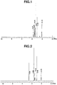
- the 1 H-NMR spectrum for MMMP ⁇ FSA is shown in FIG. 2 .
- the viscosity at 25°C was 20 cP.
- Li ⁇ FSA Lithium bis(fluorosulfonyl)amide
- a coating slurry for a positive electrode was prepared by mixing together the activated carbon Maxsorb MSP-20 (Kansai Coke and Chemicals Co., Ltd.), a conductive material (HS-100, from Denka Co., Ltd.) and the binder PVDF (Aldrich Co.) in the weight ratio 85:8:7 within the coating solvent N-methyl-2-pyrrolidone (NMP).
- NMP N-methyl-2-pyrrolidone
- the slurry was coated onto etched aluminum foil (30B, from Japan Capacitor Industrial Co., Ltd.) as the positive current collector and then rolled using a roll press, following which the NMP was removed by drying so as to form a positive electrode, thereby giving a positive electrode assembly.
- a coating slurry for a negative electrode was prepared by mixing together lithium titanate powder (lithium titanium, spinel; from Sigma-Aldrich Co.), a conductive material (HS-100), and a binder (PVDF) in the weight ratio 83:8:9 within NMP as the coating solvent.
- lithium titanate powder lithium titanium, spinel; from Sigma-Aldrich Co.
- a conductive material HS-100
- PVDF binder
- the slurry was coated onto etched aluminum foil (30CB) in the same way as for the positive electrode assembly and then rolled using a roll press, following which the NMP was removed by drying so as to form a negative electrode, thereby giving a negative electrode assembly.
- a cell was assembled by spot-welding aluminum terminals to each of the positive electrode assembly and the negative electrode assembly obtained as described above and placing a separator (TF40-35, from Nippon Kodoshi Corporation) therebetween, and the cell was inserted into an outer enclosure made of an aluminum laminate (Dai Nippon Printing Co., Ltd.).
- a predetermined amount of the liquid electrolyte for secondary batteries prepared in Working Example 1-1 was injected therein, following which electrolyte impregnation was effected by at least 12 hours of standing at 25°C under a reduced pressure of 10 kPa or below. The enclosure was then sealed by heat welding, giving a secondary battery.
- the capacitance was calculated from the total amount of energy discharged when, after being constant-current charged to 3.2 V at the one-hour rate and constant-voltage charged thereafter for 30 minutes, the battery was subsequently constant-current discharged from 3.2 V to 1.8 V at the one-hour rate. Measurement was carried out over two cycles, with the second-cycle value being treated as the capacitance. The internal resistance was measured with a resistance meter (RM 3548, from Hioki EE Corporation) following the charge/discharge test. Each of the measurements was carried out following at least two hours of standing in a thermostatic chamber at 25°C. [Table 2] Initial characteristics Capacitance (F) Internal resistance ( ⁇ ) Working Example 2-1 2.5 6.4 Working Example 2-2 3.5 5.5 Comparative Example 2-1 2.3 3.8 Comparative Example 2-2 1.7 10.4 Comparative Example 2-3 2.5 3.2
- the secondary batteries obtained were heated in a thermostatic chamber at 60°C, and cyclic charging and discharging was carried out. The number of cycles was set to one charge-discharge cycle for determining the initial performance, and 20 cycles overall. After charge/discharge cycling, the thermostatic chamber was returned to 25°C and left to stand for 2 hours, following which the performance was measured in the same way as for measurement of the initial performance. Percent changes in the capacitance and internal resistance were calculated relative to an arbitrary value of 100 % for the initially measured capacitance and internal resistance. The results are shown in Table 4.
- a positive coating paste was prepared by adjusting a positive electrode active material (LiCoO 2 , from Honjo Chemical Corporation), a conductive material (acetylene black, from Denka Co., Ltd.), and PVDF to a weight ratio therebetween of 91:3:6 and dissolving these ingredients to form a solution, and then mixing the solution together with NMP.
- the positive electrode coating paste was applied with a doctor blade onto aluminum foil to a dry film thickness of 115 ⁇ m, subsequently dried at 80°C for 2 hours and rolled so as to form a LiCoO 2 positive electrode, thereby giving a positive electrode assembly.
- a coin-type lithium secondary battery was produced by cutting both the positive electrode obtained above and a metallic lithium foil as the negative electrode to a 12-mm diameter size, sandwiching a polyolefin flat-film membrane (Hipore, from Asahi Kasei-E-materials Corporation) as the separator between the positive and negative electrodes thus cut out, and injecting and impregnating therein the liquid electrolyte obtained in Working Example 1-1.
- a polyolefin flat-film membrane Hipore, from Asahi Kasei-E-materials Corporation
- the lithium-ion battery obtained as described above was subjected to a charge/discharge test in which the upper voltage limit on charge was set to 4.2 V, the cut-off voltage on discharge was set to 3 V, and constant-current low-voltage charging and constant-current discharging were carried out at a current density of 0.025 mA/cm 2 .
- the discharge capacity per unit weight of LiCoO 2 was 122.5 mAh/g, which is sufficient for a lithium-ion battery.
- a positive electrode coating paste was prepared by adjusting a positive electrode active material (MCMB, from Osaka Gas Chemicals Co., Ltd.) and PVDF to a weight ratio therebetween of 88:12 and mixing these together with a suitable amount of NMP.
- This positive electrode coating paste was applied with a doctor blade onto aluminum foil to a dry film thickness of 75 ⁇ m, subsequently dried at 140°C for 72 hours to remove the NMP and moisture, and rolled so as to form a positive electrode, thereby giving a positive electrode assembly.
- the positive electrode obtained above and metallic lithium foil as the negative electrode were cut to a size of 12 mm diameter for the positive electrode and a size of 15 mm diameter for the negative electrode.
- the liquid electrolyte obtained in Working Example 1-1 was impregnated into a polyolefin flat-film membrane (Hipore, from Asahi Kasei E-materials Corporation) as the separator, and this was sandwiched between the cut-out positive and negative electrodes, thereby producing a lithium-air battery cell.
- This cell was placed within a positive electrode can having air holes formed therein and disposed in such a way that the positive electrode current collector faces the air holes, following which a negative electrode can was set on top and both portions of the cell enclosure were mechanically sealed, thereby producing an air battery.
- the resulting cell was placed within a glass desiccator (500 mL) equipped with a gas-flushing cock.
- the interior of the glass desiccator had a structure that allows the introduction of oxygen, enabling oxygen to be supplied to the
- the air battery obtained as described above was subjected to a charge/discharge test in which the upper voltage limit on charge was set to 3.8 V, the cut-off voltage on discharge was set to 2 V, and constant-current, low-voltage charging and constant-current discharging were carried out at a current density of 67 nA/cm 2 .
- the resulting discharge capacity was 3.3 mAh.
- the liquid electrolyte for secondary batteries of the invention has a wide potential window and an excellent withstand voltage. Moreover, secondary batteries produced using this liquid electrolyte have an excellent performance in high-temperature environments, with the internal resistance at elevated temperature greatly decreasing and the battery incurring little deterioration even when charging and discharging are repeatedly carried out at high temperature.
Description
- This invention relates to a liquid electrolyte for secondary batteries and to a secondary battery. The invention relates more particularly to a liquid electrolyte for secondary batteries which includes a specific ionic liquid and a lithium salt, and to a secondary battery that uses the same.
- In recent years, the spread of portable electronic devices such as digital cameras, smart phones and tablet devices has been remarkable. This has been accompanied by a large growth in demand for secondary batteries that can be charged and repeatedly used, as well as an increasing desire for higher capacity and higher energy density in such batteries.
- Of these, lithium-based secondary batteries with a high cell voltage of 3V or more and a large energy density per unit weight have attracted particular attention and are today the subject of vigorous development efforts.
- An electrolyte solution obtained by dissolving an ion-conductive salt such as LiBF4 or LiPF6 in an aprotic organic solvent is generally used in these lithium-based secondary batteries.
- Most lithium-based secondary batteries are designed so as to charge and discharge within the voltage range between a fully charged cell voltage of 4.2 V and an end-of discharge voltage of about 2.7 V. However, in high-voltage secondary batteries having a voltage of 4 V or more, the organic solvent and electrode active materials used are sometimes exposed to high voltages and electrically decompose.
- Various improvements in the materials making up lithium-based secondary batteries have been attempted to date in order to solve such problems. One such technology involves the use of an ionic liquid as a component of a liquid electrolyte.
- For example,
Patent Document 1 discloses a secondary power supply which uses an electrolyte that includes a lithium salt, an ionic liquid and an organic solvent. More specifically, this publication discloses a secondary power supply in which 1-ethyl-3-methylimidazolium tetrafluoroborate (abbreviated below as EMIBF4) is used as the ionic liquid and the molar ratio thereof with respect to lithium salt is set in a specific range. However, a drawback of EMIBF4 is that, although it has a relatively low viscosity, because the withstand voltage is low, the charging voltage cannot be raised, making use in a high voltage region impossible. -
Patent Document 2 discloses a liquid electrolyte which includes both an ionic liquid containing an alicyclic ammonium cation having a specific alkoxyalkyl group on a nitrogen atom, and an ion-conductive salt that is a solid at room temperature. Specifically, a liquid electrolyte containing N-methoxyethyl-N-methylpyrrolidinium tetrafluoroborate (MEMPBF4) and the like as the ionic liquid, and an electrical double-layer capacitor that uses the same are disclosed. However, MEMPBF4 does not have a sufficient ability to dissolve lithium salts, and so increasing the lithium salt concentration is difficult. In addition, because it has a high viscosity, when the ionic liquid alone is used as a liquid electrolyte, the internal resistance of the battery rises. -
Patent Document 3 discloses a lithium-ion capacitor which uses a liquid electrolyte that includes both a lithium salt and an ionic liquid, wherein the lithium salt and the ionic liquid have the same anion. Specifically, a capacitor is disclosed in which a compound such as N-methyl-N-butylpyrrolidinium bis(fluorosulfonyl)amide (MBPYFSA) is used as the ionic liquid and lithium bis(fluorosulfonyl)amide is used as the lithium salt. However, in the case of a compound such as MBPYFSA, because the ionic liquid itself has a higher viscosity than EMIBF4, adding a lithium salt further increases the viscosity, lowering the charge-discharge characteristics when such an electrolyte is included in a lithium-ion battery. -
Patent Document 4 discloses various bis(fluorosulfonyl)amide anion-containing ionic liquids and methods for their synthesis, and also discloses that these ionic liquids can be used as electrolyte materials in secondary batteries and the like. Although N-methoxyethyl-N-methylpyrrolidinium bis(fluorosulfonyl)amide (MEMP·FSA) is disclosed here as a specific ionic liquid, no mention is made of the characteristics of secondary batteries in which this is used. - Because there are cases in which, depending on the service environment and conditions, electrical energy storage devices such as secondary batteries are exposed to elevated temperatures, stability under such elevated temperatures is also demanded. However, none of the foregoing literature makes any mention of findings relating to the performance of secondary batteries in high-temperature environments.
-
- Patent Document 1:
JP No. 4617727 B - Patent Document 2:
JP No. 5083577 B - Patent Document 3:
JP-A 2014-183161 - Patent Document 4:
CN-A 101747243 -
EP 1837333 A1 discloses a quaternary ammonium salt represented by formula (1) disclosed therein. The quaternary ammonium salt cation is pyrrolidinium-based and a number of possible anions are proposed. -
EP 2023434 A1 discloses an electrolyte comprising an ionic liquid and an aprotic dipolar solvent. The ionic liquid is electrochemically stable at 4.5 V, has a viscosity of less than 300 mPa.s at 20°C and a conductivity of 1.0 mScm-1 at 20°C. The solvent is present in an amount of 20-60 vol% based on the electrolyte. The electrolyte has a conductivity twice that of the ionic liquid. An additive with a polymerizable functional group and lithium salt are also disclosed. -
JP 2011-253677 A -
EP 1642894 A1 discloses a quaternary ammonium salt represented by formula (1) disclosed therein, and an electrolytic solution and electrochemical device using the salt. -
EP 2549577 A1 discloses a flame-retardant lithium secondary battery having a positive electrode including a positive electrode active material of formula LiNixMnyO4 in which x + y = 2 and x: y = 27.5:72.5 to 22.5:77.5, and a non-aqueous electrolyte solution having a solvent which is an ionic liquid containing bis(fluorosulfonyl)imide anions as anionic component. - Matsumoto et al. (J. Power Sources, 160, 2006, 1308-1313) disclose, inter alia, the results of a charge-discharge cycling test of a Li/LiCoO2 cell containing specific ionic liquids based on bis(fluorosulfonyl)imide as electrolyte media.
-
JP 2014-197472 A -
JP 2013-089365 A -
JP 2011-134459 A - In light of the above circumstances, the object of this invention is to provide a liquid electrolyte for secondary batteries that includes an ionic liquid and a lithium salt, and that affords secondary batteries having a good performance particularly in high-temperature environments.
- As a result of extensive investigations, the inventors have discovered that ionic liquids consisting of a specific pyrrolidinium cation and the bis(fluorosulfonyl)amide anion have an excellent ability to dissolve lithium salts, and that the outstanding properties of such ionic liquids are not lost even when they are mixed with a lithium salt. The inventors have also found that secondary batteries obtained using a liquid electrolyte containing this ionic liquid and a lithium salt exhibit a good battery performance even in a high-temperature environment.
- Accordingly, this invention provides:
- 1. A liquid electrolyte for a secondary battery, characterized by comprising an ionic liquid of formula (1) and a lithium salt

- 2. The liquid electrolyte for a secondary battery of 1 above, wherein R1 and R2 are each independently a methyl group or an ethyl group;
- 3. The liquid electrolyte for a secondary battery of 1 or 2 above, wherein R1 and R2 are both methyl groups;
- 4. The liquid electrolyte for a secondary battery of any of 1 to 3 above which is free of organic solvent;
- 5. The liquid electrolyte for a secondary battery of any of 1 to 4 above which consists solely of the ionic liquid of formula (1) and a lithium salt;
- 6. The liquid electrolyte for a secondary battery of any of 1 to 5 above, wherein the lithium salt is one or more selected from the group consisting of lithium tetrafluoroborate, lithium hexafluorophosphate, lithium bis(trifluoromethanesulfonyl)amide and lithium bis(fluorosulfonyl)amide;
- 7. A secondary battery characterized by comprising the liquid electrolyte for a secondary battery of any of 1 to 6 above; and
- 8. A secondary battery according to 7 above comprising a positive electrode having a positive electrode current collector and a positive electrode active material layer formed on a surface thereof, a negative electrode having a negative electrode current collector and a negative electrode active material layer formed on a surface thereof, a separator interposed between the electrodes, and a liquid electrolyte,
wherein the liquid electrolyte is the liquid electrolyte for a secondary battery of any of 1 to 6 above and the negative electrode active material layer includes a lithium composite oxide. - 9. A secondary battery according to 7 above which is an air battery comprising a positive electrode (air electrode) layer, a negative electrode layer, and a liquid electrolyte layer disposed between the electrodes, wherein the liquid electrolyte layer comprises a liquid electrolyte for a secondary battery of any of 1 to 6 above.
- An advantage of this invention is that it provides an ionic liquid-containing liquid electrolyte in which a lithium salt can be dissolved without losing the excellent properties of the ionic liquid, and which affords a secondary battery having an excellent performance in a high-temperature environment.
- The ionic liquid used in this liquid electrolyte has a high withstand voltage, and thus undergoes little deterioration even in secondary batteries where the potential of the liquid electrolyte reaches a high-voltage region. Moreover, secondary batteries obtained using this liquid electrolyte have a lower internal resistance at elevated temperatures and undergo little deterioration even when charging and discharging are repeatedly carried out in a high-temperature environment.
- In addition, the ionic liquid used in the liquid electrolyte of the invention has an excellent ability to dissolve lithium salts and also has a relatively low viscosity. As a result, an organic solvent is either not used or, when used, the amount thereof can be made very small, enabling a secondary battery having an excellent safety to be provided.
-
- [
FIG. 1] FIG. 1 is a 1H-NMR spectrum of the MEMP·FSA obtained in Synthesis Example 1. - [
FIG. 2] FIG. 2 is a 1H-NMR spectrum of the MMMP·FSA obtained in Synthesis Example 2. - [
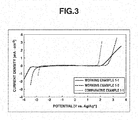
FIG. 3] FIG. 3 is a graph showing the results of potential window measurements on the liquid electrolytes prepared in Working Examples 1-1 and 1-2 and in Comparative Example 1-1. - The invention is described more fully below.
- The liquid electrolyte for a secondary battery according to the invention includes an ionic liquid of formula (1) and a lithium salt.

- In the formula, R1 and R2 are each independently an alkyl group of 1 to 5 carbon atoms, and n is 1 or 2.
- The alkyl group of 1 to 5 carbon atoms may be linear, branched or cyclic. Illustrative examples include methyl, ethyl, n-propyl, i-propyl, c-propyl, n-butyl, i-butyl, s-butyl, t-butyl, c-butyl, n-pentyl and c-pentyl groups. A linear alkyl group is preferred, with methyl and ethyl groups being more preferred, and a methyl group being even more preferred.
- The ionic liquid used in the invention can be prepared by, for example, the method described in
Patent Document 4. For instance, the ionic liquid can be obtained by carrying out an anion exchange reaction between an N-alkoxyalkyl-N-alkylpyrrolidinium halide (e.g., chloride, bromide) prepared in the usual manner and a bis(fluorosulfonyl)amide salt of an alkali metal (e.g., sodium, potassium) within an aqueous solvent. - Examples of cation structures in the ionic liquid that can be suitably used in this invention include, but are not limited to, those shown below.

- Of these, in terms of having a better thermal stability, cation structure (A) below is preferred; in terms of having a lower viscosity, cation structure (B) below is preferred.

- The lithium salt which is the other ingredient making up the inventive liquid electrolyte for secondary batteries is exemplified by various lithium salts that have hitherto been widely used in lithium secondary batteries and other secondary batteries. Illustrative examples include lithium tetrafluoroborate, lithium hexafluorophosphate, lithium bis(trifluoromethanesulfonyl)amide, lithium bis(fluorosulfonyl)amide, lithium perchlorate, lithium acetate, lithium trifluoroacetate, lithium benzoate, lithium p-toluenesulfonate, lithium nitrate, lithium bromide and lithium iodide. Of these, lithium tetrafluoroborate, lithium hexafluorophosphate, lithium bis(trifluoromethanesulfonyl)amide and lithium bis(fluorosulfonyl)amide are preferred.
- The lithium salt concentration in the liquid electrolyte for a secondary battery, although not particularly limited, is generally from about 0.5 to about 3 mol/L, preferably from about 0.8 to about 2 mol/L, and more preferably from about 0.9 to about 1.5 mol/L.
- A nonaqueous organic solvent commonly used for preparing electrolyte solutions may also be used in the liquid electrolyte for secondary batteries of the invention. Because the ionic liquid used in this invention has a relatively low viscosity itself and also has a good ability to dissolve lithium salts, even in cases where a nonaqueous solvent is used, the amount of use thereof is preferably not more than 10 wt%, more preferably not more than 5 wt%, and optimally 0 wt% (meaning that the liquid component consists only of the ionic liquid) of the liquid electrolyte.
- In cases where a nonaqueous organic solvent is used together in the liquid electrolyte of the invention, illustrative examples of this solvent include acyclic ethers such as dibutyl ether, 1,2-dimethoxyethane, 1,2-ethoxymethoxyethane, methyl diglyme, methyl triglyme, methyl tetraglyme, ethyl glyme, ethyl diglyme, butyl diglyme, ethyl cellosolve, ethyl carbitol, butyl cellosolve and butyl carbitol; heterocyclic ethers such as tetrahydrofuran, 2-methyltetrahydrofuran, 1,3-dioxolane and 4,4-dimethyl-1,3-dioxane; lactones such as γ-butyrolactone, γ-valerolactone, δ-valerolactone, 3-methyl-1,3-oxazolidin-2-one and 3-ethyl-1,3-oxazolidin-2-one; amides such as N-methylformamide, N,N-dimethylformamide, N-methylacetamide and N-methylpyrrolidinone; carbonates such as diethyl carbonate, dimethyl carbonate, ethyl methyl carbonate, propylene carbonate, ethylene carbonate and butylene carbonate; imidazolines such as 1,3-dimethyl-2-imidazolidinone; and nitriles such as acetonitrile and propionitrile. These may be used singly, or two or more may be used in admixture.
- The secondary battery according to the invention is not particularly limited, provided it includes the above-described liquid electrolyte for secondary batteries. For example, the inventive liquid electrolyte for secondary batteries may be employed in an ordinary secondary battery having a positive electrode made of a positive electrode current collector and a positive electrode active material layer formed on the surface thereof, a negative electrode made of a negative electrode current collector and a negative electrode active material layer formed on the surface thereof, and a separator interposed between these electrodes; or may be employed in an air battery having a positive electrode (air electrode) layer, a negative electrode layer, and a liquid electrode layer disposed between the electrodes.
- The materials making up this secondary battery are not particularly limited, and may be suitably selected and used from among conventional known materials. Some examples are given below.
- Illustrative examples of positive electrode current collectors include aluminum foil and aluminum alloy foil. Three dimensional porous bodies thereof, such as foams or nonwoven fabric-like bodies, may be used as the current collector.
- Specific examples of positive electrode active materials include carbonaceous materials such as activated carbon and carbon nanotube that are able to reversibly support lithium; and lithium oxides having an olivine-type crystal structure, a layered rock salt-type crystal structure or a spinel-type crystal structure. Illustrative examples of activated carbon starting materials include coconut shell, phenolic resin and petroleum coke. Methods for activating the activated carbon starting material include steam activation and molten alkali activation. Illustrative examples of lithium oxides include composite oxides of the general formula LiMPO4 (where M is one or more from among Fe(II), Mn(II), Co(II) and Ni(II)), lithium cobalt oxide (LiCoO2), LiNiO2, LiMnO2, Li2MnO3, and NiCo systems such as LiNi0.8Co0.2O2.
- Illustrative examples of negative electrode current collectors include copper foil, copper alloy foil, nickel foil, nickel alloy foil, stainless steel foil, aluminum foil and aluminum alloy foil.
- Illustrative examples of negative electrode active materials include, without particular limited, substances capable of intercalating and deintercalating lithium ions, such as carbonaceous materials (graphite, etc.), silicon oxides, silicon alloys, tin oxides, tin alloys, lithium, and metals that can form lithium alloys, such as aluminum, lead, tin, indium, bismuth, silver, barium, calcium, mercury, palladium, platinum, tellurium, zinc and lanthanum. These may be of one type used alone, or two or more types may be used in combination. A carbonaceous material or lithium composite oxide is preferred from the standpoint of safety. In addition, a substance containing titanium (Ti), lithium (Li) or both Ti and Li (e.g., lithium titanate) is preferred from the standpoint of the charge-discharge characteristics at a high current density.
- The positive electrode active material and the negative electrode active material may be used together with a conductive additive.
- Illustrative examples of conductive additives include carbon black, ketjen black, acetylene black, carbon whiskers, carbon fibers, natural graphite, synthetic graphite, titanium oxide, ruthenium oxide, aluminum and nickel.
- The positive electrode and negative electrode active material layers can be formed by coating the current collector with an electrode slurry containing the above described active material, a binder polymer and, optionally, a conductive additive with a solvent, and then drying under applied heat, where necessary.
- Binder polymers that are suitably selected from among known materials may be used. Illustrative examples include polyvinylidene fluoride (PVdF), polyvinyl pyrrolidone, polytetrafluoroethylene, tetrafluoroethylene-hexafluoropropylene copolymers, vinylidene fluoride-hexafluoropropylene copolymers ([P(VDF-HFP)], vinylidene fluoride-chlorotrifluoroethylene copolymers [P(VDF-CTFE)], polyvinyl alcohol, ethylene-propylene-diene terpolymers, styrene-butadiene rubbers and carboxymethylcellulose (CMC).
- The solvent is selected according to the type of binder polymer, with N-methyl-2-pyrrolidone or water generally being used.
- If necessary, the electrodes having an active material layer formed therein may be pressed.
- Illustrative examples of the separator include separators made of a polyolefin such as polyethylene or polypropylene, separators made of a polyester such as polyethylene terephthalate, polyamide separators, polyimide separators, cellulose-based separators and glass-fiber-based separators.
- The secondary battery of the invention can be obtained by stacking, fan-folding or winding and, if necessary, forming into a coin shape, a battery assembly composed of the positive electrode, the negative electrode and a separator interposed therebetween. The assembly is then placed within a battery housing such as a battery can or a laminate pack, after which it is filled with the inventive liquid electrolyte for secondary batteries. The housing is then mechanically sealed if it is a can or heat-sealed if it is a laminate pack.
- The invention is illustrated more fully below by way of Synthesis Examples, Working Examples and Comparative Examples, although these Examples are not intended to limit the invention.
- The analytical instruments used in the Examples were as follows.
- [1] 1H-NMR Spectrometer
- Instrument: AL-400, from JEOL Ltd.
- Solvent: Deuterated dimethylsulfoxide
- [2] Viscometer
Instrument: BROOKFIELD programmable rheometer - [3] Electrical Conductivity
Instrument: CM-30R conductivity meter, from DKK-Toa Corporation - [4] Potential Window
Instrument: HSV-100 Standard Voltammetry Tool, from Hokuto Denko Corporation - [5] Internal Resistance
Instrument: RM 3548 resistance meter, from Hioki EE Corporation -

- Pyrrolidine (Wako Pure Chemical Industries, Ltd.), 1.51 parts by weight, and 2-methoxyethyl chloride (Kanto Chemical Co., Ltd.), 1.00 part by weight, were mixed together and reacted for 1 hour under refluxing. Following the reaction, the reaction mixture separated into two layers. When left to cool for a while, the bottom layer solidified. The top layer alone was collected by decantation and purified by vacuum distillation, giving 0.96 part by weight of the target substance N-2-methoxyethylpyrrolidine (boiling point, 76°C; vapor pressure, 45 mmHg) in a yield of 70 %.
- Next, 1.00 part by weight of the N-2-methoxyethylpyrrolidine was mixed with a two-fold volume of toluene (Wako Pure Chemical Industries, Ltd.), the mixture was placed in an autoclave, and the interior of the system was nitrogen purged. The system was closed, after which about 1.00 part by weight of methyl chloride gas (Nittoku Chemicals) was added under stirring at room temperature. During introduction of the methyl chloride gas, the temperature and internal pressure both rose; at the highest point, the temperature rose to about 53°C and the internal pressure rose to 5.5 kgf/cm2 (about 5.4×10⁵ Pa). The reaction was effected in this way without heating; after 2 days, about 0.75 part by weight of methyl chloride gas was added. The reaction was additionally continued for one day, after which the pressure was released. The crystals that formed within the system were separated off by vacuum filtration and then dried using a vacuum pump, thereby giving 1.29 parts by weight of N-2-methoxyethyl-N-methylpyrrolidinium chloride (yield, 92 %).
- An equal volume of deionized water was added to 1.00 part by weight of the resulting N-2-methoxyethyl-N-methylpyrrolidinium chloride, and the chloride was dissolved under stirring. This solution was added under stirring to a solution of 1.29 parts by weight of potassium bis(fluorosulfonyl)amide (Kanto Chemical Co., Ltd.) dissolved in an equal volume of deionized water. The reaction was effected at room temperature and, after 3 or more hours had elapsed, the reaction mixture that had separated into two layers was collected as separate layers. The organic layer on the bottom was washed twice with deionized water and then dried using a vacuum pump, giving 1.50 parts by weight of the target substance N-2-methoxyethyl-N-methylpyrrolidinium bis(fluorosulfonyl)amide (MEMP·FSA) (yield, 83 %). The 1H-NMR spectrum for MEMP·FSA is shown in
FIG. 1 . The viscosity at 25°C was 35 cP. -

- A solution of 14.4 parts by weight of N-methylpyrrolidine (Wako Pure Chemical Industries, Ltd.) dissolved in 200 parts by weight of tetrahydrofuran (Wako Pure Chemical Industries, Ltd.) was ice-cooled, and 17.1 parts of chloromethyl methyl ether (Tokyo Chemical Industry Co., Ltd.) was added under stirring. After allowing these to react overnight, the precipitated solids were collected by filtration in vacuo using a Kiriyama funnel. The resulting white solid was dried using a vacuum pump, giving 26.7 parts by weight of the intermediate N-methoxymethyl-N-methylpyrrolidinium chloride (yield, 96 %).
- Next, 8.58 parts by weight of the N-methoxymethyl-N-methylpyrrolidinium chloride was dissolved in 10 parts by weight of deionized water. This solution was added under stirring to a solution of 12.5 parts by weight of potassium bis(fluorosulfonyl)amide (Kanto Chemical Co., Ltd.) dissolved in 5 parts by weight of deionized water. Stirring was continued overnight at room temperature, following which the reaction mixture that had separated into two layers was collected as separate layers. The organic layer on the bottom was washed four times with deionized water and then dried using a vacuum pump, giving 10.2 parts by weight of the target substance N-methoxymethyl-N-methylpyrrolidinium bis(fluorosulfonyl)amide (MMMP·FSA) (yield, 63 %). The 1H-NMR spectrum for MMMP·FSA is shown in
FIG. 2 . The viscosity at 25°C was 20 cP. - Lithium bis(fluorosulfonyl)amide (Li·FSA, from Kanto Chemical Co., Ltd.) was added to the MEMP·FSA obtained in Synthesis Example 1, thereby preparing a liquid electrolyte for secondary batteries having a Li·FSA concentration of 1 mol/L.
- Aside from using the MMMP·FSA obtained in Synthesis Example 2, a liquid electrolyte for secondary batteries was prepared in the same way as in Working Example 1-1.
- Aside from using 1-ethyl-3-methylimidazolinium tetrafluoroborate (EMI·BF4, from Kanto Chemical Co., Ltd.) instead of MEMP·FSA, a liquid electrolyte for secondary batteries was prepared in the same way as in Working Example 1-1.
- Aside from using 2-methoxyethyl-N-methylpyrrodinium tetrafluoroborate (MEMP·BF4) synthesized by the method described in
Patent Document 2 instead of MEMP·FSA, an attempt was made to prepare a liquid electrolyte for secondary batteries in the same way as in Working Example 1-1. However, dissolution of the Li·FSA to aconcentration 1 mol/L was not possible, resulting in a cloudy liquid. - Aside from using propylene carbonate (Kishida Chemical Co., Ltd.) instead of MEMP·FSA and using lithium tetrafluoroborate (Li·BF4, from Kishida Chemical Co., Ltd.) instead of Li·FSA, a liquid electrolyte for secondary batteries was prepared in the same way as in Working Example 1-1.
- The electrical conductivities of each of the liquid electrolytes prepared above (in Comparative Example 1-2, the cloudy liquid) were measured. Measurement was carried out in a 25°C thermostatic chamber using a conductivity meter (CM-30R, from DKK-Toa Corporation). The results are shown in Table 1.
[Table 1] Electrical conductivity (mS/cm) Working Example 1-1 1.9 Working Example 1-2 2.9 Comparative Example 1-1 4.5 Comparative Example 1-2 1.5 Comparative Example 1-3 3.2 - In addition, the potential windows for each of the liquid electrolytes obtained in Working Example 1-1, Working Example 1-2 and Comparative Example 1-1 were measured. Those results are shown in
FIG. 3 . - As demonstrated in
FIG. 3 , the potential windows of the liquid electrolytes in Working Examples 1-1 and 1-2 were confirmed to be broader than the potential window of the liquid electrolyte in Comparative Example 1-1. - A coating slurry for a positive electrode was prepared by mixing together the activated carbon Maxsorb MSP-20 (Kansai Coke and Chemicals Co., Ltd.), a conductive material (HS-100, from Denka Co., Ltd.) and the binder PVDF (Aldrich Co.) in the weight ratio 85:8:7 within the coating solvent N-methyl-2-pyrrolidone (NMP).
- The slurry was coated onto etched aluminum foil (30B, from Japan Capacitor Industrial Co., Ltd.) as the positive current collector and then rolled using a roll press, following which the NMP was removed by drying so as to form a positive electrode, thereby giving a positive electrode assembly.
- A coating slurry for a negative electrode was prepared by mixing together lithium titanate powder (lithium titanium, spinel; from Sigma-Aldrich Co.), a conductive material (HS-100), and a binder (PVDF) in the weight ratio 83:8:9 within NMP as the coating solvent.
- The slurry was coated onto etched aluminum foil (30CB) in the same way as for the positive electrode assembly and then rolled using a roll press, following which the NMP was removed by drying so as to form a negative electrode, thereby giving a negative electrode assembly.
- A cell was assembled by spot-welding aluminum terminals to each of the positive electrode assembly and the negative electrode assembly obtained as described above and placing a separator (TF40-35, from Nippon Kodoshi Corporation) therebetween, and the cell was inserted into an outer enclosure made of an aluminum laminate (Dai Nippon Printing Co., Ltd.). A predetermined amount of the liquid electrolyte for secondary batteries prepared in Working Example 1-1 was injected therein, following which electrolyte impregnation was effected by at least 12 hours of standing at 25°C under a reduced pressure of 10 kPa or below. The enclosure was then sealed by heat welding, giving a secondary battery.
- Aside from using the liquid electrolyte for secondary batteries prepared in Working Example 1-2, a secondary battery was produced in the same way as in Working Example 2-1.
- Aside from using the liquid electrolyte for secondary batteries prepared in Comparative Example 1-1, a secondary battery was produced in the same way as in Working Example 2-1.
- Aside from using the liquid electrolyte for secondary batteries (cloudy liquid) prepared in Comparative Example 1-2, a secondary battery was produced in the same way as in Working Example 2-1.
- Aside from using the liquid electrolyte for secondary batteries prepared in Comparative Example 1-3, a secondary battery was produced in the same way as in Working Example 2-1.
- The initial characteristics of the secondary batteries produced as described above were measured by the following methods. The results are shown in Table 2.
- First, the capacitance was calculated from the total amount of energy discharged when, after being constant-current charged to 3.2 V at the one-hour rate and constant-voltage charged thereafter for 30 minutes, the battery was subsequently constant-current discharged from 3.2 V to 1.8 V at the one-hour rate. Measurement was carried out over two cycles, with the second-cycle value being treated as the capacitance. The internal resistance was measured with a resistance meter (RM 3548, from Hioki EE Corporation) following the charge/discharge test. Each of the measurements was carried out following at least two hours of standing in a thermostatic chamber at 25°C.
[Table 2] Initial characteristics Capacitance (F) Internal resistance (Ω) Working Example 2-1 2.5 6.4 Working Example 2-2 3.5 5.5 Comparative Example 2-1 2.3 3.8 Comparative Example 2-2 1.7 10.4 Comparative Example 2-3 2.5 3.2 - Next, the secondary batteries obtained were left to stand for at least 2 hours in a thermostatic chamber at 60°C, and the capacitance and internal resistance were measured in the same way as for measurement of the initial performance. The results are shown in Table 3.
- As shown in Table 3, owing to the rise in temperature, increases in capacitance were observed in each secondary battery. Also, the secondary batteries obtained in Working Examples 2-1 and 2-2 underwent a large decrease in internal resistance at 60°C, with the internal resistance falling to about 1/6th of the value obtained when the initial performance was measured.
[Table 3] 60°C Capacitance (F) Internal resistance (Ω) Working Example 2-1 3.5 1.1 Working Example 2-2 4.2 0.9 Comparative Example 2-1 3.0 2.3 Comparative Example 2-2 1.8 4.7 Comparative Example 2-3 2.7 1.1 - In addition, the secondary batteries obtained were heated in a thermostatic chamber at 60°C, and cyclic charging and discharging was carried out. The number of cycles was set to one charge-discharge cycle for determining the initial performance, and 20 cycles overall. After charge/discharge cycling, the thermostatic chamber was returned to 25°C and left to stand for 2 hours, following which the performance was measured in the same way as for measurement of the initial performance. Percent changes in the capacitance and internal resistance were calculated relative to an arbitrary value of 100 % for the initially measured capacitance and internal resistance. The results are shown in Table 4.
- As shown in Table 4, when cycling was carried out at an elevated temperature in the secondary battery produced in Comparative Example 2-1, the capacitance decreased. Also, the internal resistances of the secondary batteries produced in Working Examples 2-1 and 2-2 tended to decrease or remain substantially the same when cycling was carried out at 60°C, whereas the internal resistances of the other secondary batteries tended to rise when cycling was carried out at 60°C.
[Table 4] After 20 cycles at 60°C Retention of capacitance (%) Retention of internal resistance (%) Working Example 2-1 99 98 Working Example 2-2 98 101 Comparative Example 2-1 87 118 Comparative Example 2-2 95 107 Comparative Example 2-3 99 102 - A positive coating paste was prepared by adjusting a positive electrode active material (LiCoO2, from Honjo Chemical Corporation), a conductive material (acetylene black, from Denka Co., Ltd.), and PVDF to a weight ratio therebetween of 91:3:6 and dissolving these ingredients to form a solution, and then mixing the solution together with NMP. The positive electrode coating paste was applied with a doctor blade onto aluminum foil to a dry film thickness of 115 µm, subsequently dried at 80°C for 2 hours and rolled so as to form a LiCoO2 positive electrode, thereby giving a positive electrode assembly.
- A coin-type lithium secondary battery was produced by cutting both the positive electrode obtained above and a metallic lithium foil as the negative electrode to a 12-mm diameter size, sandwiching a polyolefin flat-film membrane (Hipore, from Asahi Kasei-E-materials Corporation) as the separator between the positive and negative electrodes thus cut out, and injecting and impregnating therein the liquid electrolyte obtained in Working Example 1-1.
- The lithium-ion battery obtained as described above was subjected to a charge/discharge test in which the upper voltage limit on charge was set to 4.2 V, the cut-off voltage on discharge was set to 3 V, and constant-current low-voltage charging and constant-current discharging were carried out at a current density of 0.025 mA/cm2.
- As a result, the discharge capacity per unit weight of LiCoO2 was 122.5 mAh/g, which is sufficient for a lithium-ion battery.
- A positive electrode coating paste was prepared by adjusting a positive electrode active material (MCMB, from Osaka Gas Chemicals Co., Ltd.) and PVDF to a weight ratio therebetween of 88:12 and mixing these together with a suitable amount of NMP. This positive electrode coating paste was applied with a doctor blade onto aluminum foil to a dry film thickness of 75 µm, subsequently dried at 140°C for 72 hours to remove the NMP and moisture, and rolled so as to form a positive electrode, thereby giving a positive electrode assembly.
- The positive electrode obtained above and metallic lithium foil as the negative electrode were cut to a size of 12 mm diameter for the positive electrode and a size of 15 mm diameter for the negative electrode. The liquid electrolyte obtained in Working Example 1-1 was impregnated into a polyolefin flat-film membrane (Hipore, from Asahi Kasei E-materials Corporation) as the separator, and this was sandwiched between the cut-out positive and negative electrodes, thereby producing a lithium-air battery cell. This cell was placed within a positive electrode can having air holes formed therein and disposed in such a way that the positive electrode current collector faces the air holes, following which a negative electrode can was set on top and both portions of the cell enclosure were mechanically sealed, thereby producing an air battery. The resulting cell was placed within a glass desiccator (500 mL) equipped with a gas-flushing cock. The interior of the glass desiccator had a structure that allows the introduction of oxygen, enabling oxygen to be supplied to the positive electrode.
- The air battery obtained as described above was subjected to a charge/discharge test in which the upper voltage limit on charge was set to 3.8 V, the cut-off voltage on discharge was set to 2 V, and constant-current, low-voltage charging and constant-current discharging were carried out at a current density of 67 nA/cm2. The resulting discharge capacity was 3.3 mAh.
- As noted above, the liquid electrolyte for secondary batteries of the invention has a wide potential window and an excellent withstand voltage. Moreover, secondary batteries produced using this liquid electrolyte have an excellent performance in high-temperature environments, with the internal resistance at elevated temperature greatly decreasing and the battery incurring little deterioration even when charging and discharging are repeatedly carried out at high temperature.
Claims (9)
- A liquid electrolyte for a secondary battery, characterized by comprising an ionic liquid of formula (1) and a lithium salt

- The liquid electrolyte for a secondary battery of claim 1, wherein R1 and R2 are each independently a methyl group or an ethyl group.
- The liquid electrolyte for a secondary battery of claim 1 or 2, wherein R1 and R2 are both methyl groups.
- The liquid electrolyte for a secondary battery of any one of claims 1 to 3 which is free of organic solvent.
- The liquid electrolyte for a secondary battery of any one of claims 1 to 4 which consists solely of the ionic liquid of formula (1) and a lithium salt.
- The liquid electrolyte for a secondary battery of any one of claims 1 to 5, wherein the lithium salt is one or more selected from the group consisting of lithium tetrafluoroborate, lithium hexafluorophosphate, lithium bis(trifluoromethanesulfonyl)amide and lithium bis(fluorosulfonyl)amide.
- A secondary battery characterized by comprising the liquid electrolyte for a secondary battery of any one of claims 1 to 6.
- A secondary battery according to claim 7, comprising a positive electrode having a positive electrode current collector and a positive electrode active material layer formed on a surface thereof, a negative electrode having a negative electrode current collector and a negative electrode active material layer formed on a surface thereof, a separator interposed between the electrodes, and a liquid electrolyte,
wherein the liquid electrolyte is the liquid electrolyte for a secondary battery of any one of claims 1 to 6 and the negative electrode active material layer includes a lithium composite oxide. - A secondary battery according to claim 7 which is an air battery comprising a positive electrode (air electrode) layer, a negative electrode layer, and a liquid electrolyte layer disposed between the electrodes,
wherein the liquid electrolyte layer comprises a liquid electrolyte for a secondary battery according to any one of claims 1 to 6.
Applications Claiming Priority (2)
| Application Number | Priority Date | Filing Date | Title |
|---|---|---|---|
| JP2014258863A JP6592891B2 (en) | 2014-12-22 | 2014-12-22 | Secondary battery electrolyte and secondary battery |
| PCT/JP2015/080489 WO2016103905A1 (en) | 2014-12-22 | 2015-10-29 | Electrolyte solution for secondary batteries, and secondary battery |
Publications (3)
| Publication Number | Publication Date |
|---|---|
| EP3240094A1 EP3240094A1 (en) | 2017-11-01 |
| EP3240094A4 EP3240094A4 (en) | 2018-07-04 |
| EP3240094B1 true EP3240094B1 (en) | 2020-06-03 |
Family
ID=56149941
Family Applications (1)
| Application Number | Title | Priority Date | Filing Date |
|---|---|---|---|
| EP15872474.0A Active EP3240094B1 (en) | 2014-12-22 | 2015-10-29 | Electrolyte solution for secondary batteries, and secondary battery comprising the same |
Country Status (6)
| Country | Link |
|---|---|
| US (1) | US10763548B2 (en) |
| EP (1) | EP3240094B1 (en) |
| JP (1) | JP6592891B2 (en) |
| KR (1) | KR20170095889A (en) |
| CN (1) | CN107112592A (en) |
| WO (1) | WO2016103905A1 (en) |
Families Citing this family (10)
| Publication number | Priority date | Publication date | Assignee | Title |
|---|---|---|---|---|
| JP2018170271A (en) * | 2017-03-29 | 2018-11-01 | Tdk株式会社 | Electrolyte solution for lithium ion secondary battery, and lithium ion secondary battery |
| JP7119452B2 (en) * | 2017-03-29 | 2022-08-17 | Tdk株式会社 | Electrolyte for lithium ion secondary battery and lithium ion secondary battery |
| US10505219B2 (en) * | 2017-05-26 | 2019-12-10 | Toyota Motor Engineering & Manufacturing North America, Inc. | Artificial SEI transplantation |
| US10868339B2 (en) * | 2017-12-05 | 2020-12-15 | Toyota Motor Engineering & Manufacturing North America, Inc. | Aqueous electrolytes with bis(fluorosulfonyl)imide salt electrolyte and ionic liquid system and batteries using the electrolyte system |
| CN108232295B (en) * | 2017-12-21 | 2020-11-17 | 北京科技大学 | Ionic liquid-based electrolyte for lithium-air battery and lithium-air battery system thereof |
| US20210313615A1 (en) * | 2018-09-04 | 2021-10-07 | National Institute For Materials Science | An electrolyte for lithium air batteries, and a lithium air battery using the same |
| CN113632285B (en) * | 2019-03-25 | 2023-10-03 | 日清纺控股株式会社 | Additive for electrolyte |
| FR3095551B1 (en) * | 2019-04-26 | 2021-04-02 | Renault Sas | Electrolyte for an electrochemical accumulator comprising a particular ionic liquid |
| CN112448032B (en) * | 2019-09-02 | 2022-03-22 | 华南师范大学 | New application of lithium benzoate |
| CN112408437B (en) * | 2020-11-19 | 2023-03-28 | 江西天新药业股份有限公司 | Method for recovering lithium salt |
Family Cites Families (24)
| Publication number | Priority date | Publication date | Assignee | Title |
|---|---|---|---|---|
| CA2441981C (en) | 2001-03-26 | 2012-05-15 | Nisshinbo Industries, Inc. | Ionic liquids, electrolyte salts for electrical storage devices, liquid electrolytes for electrical storage devices, electrical double-layer capacitors, and secondary batteries |
| JP3831939B2 (en) * | 2001-11-12 | 2006-10-11 | ソニー株式会社 | battery |
| RU2329257C2 (en) | 2003-07-01 | 2008-07-20 | Оцука Кемикал Ко., Лтд. | Electrolyte, electrolytic mixture and solution, condenser, secondary lithium cell and method of obtaining quaternary ammonium salt |
| JP4617727B2 (en) | 2004-06-08 | 2011-01-26 | パナソニック株式会社 | Secondary power supply |
| WO2006077894A1 (en) * | 2005-01-12 | 2006-07-27 | Otsuka Chemical Co., Ltd. | Quaternary ammonium salt, electrolyte, electrolyte solution and electrochemical device |
| JP2006236829A (en) | 2005-02-25 | 2006-09-07 | Nisshinbo Ind Inc | Ionic liquid, nonaqueous electrolyte for electricity accumulation device and electricity accumulation device |
| EP2023434B1 (en) | 2007-07-23 | 2016-09-07 | Litarion GmbH | Electrolyte preparations for energy storage devices based on ionic fluids |
| CN101747243A (en) | 2008-11-28 | 2010-06-23 | 华中科技大学 | Ionic liquid prepared through diimine (vikane) and (perfluoroalkglsulfonyl fluorosulfonyl group) imine alkali salt |
| CN102356500A (en) * | 2009-03-18 | 2012-02-15 | 日本合成化学工业株式会社 | Ionic liquid, electrolyte, lithium secondary battery comprising same, and process for producing ionic liquid |
| JP2011134459A (en) * | 2009-12-22 | 2011-07-07 | Konica Minolta Holdings Inc | Electrolytic composition, secondary battery, and compound |
| CN103119773A (en) | 2010-03-19 | 2013-05-22 | 第一工业制药株式会社 | Lithium secondary battery using ionic liquid |
| JP5557010B2 (en) * | 2010-06-01 | 2014-07-23 | トヨタ自動車株式会社 | Electrolyte production method |
| JP5778625B2 (en) * | 2011-06-03 | 2015-09-16 | 株式会社半導体エネルギー研究所 | Ionic liquid and power storage device including ionic liquid |
| WO2013051302A1 (en) | 2011-10-05 | 2013-04-11 | 国立大学法人東北大学 | Secondary battery |
| JP5726707B2 (en) | 2011-10-14 | 2015-06-03 | エレクセル株式会社 | Lithium secondary battery |
| JP2014167873A (en) * | 2013-02-28 | 2014-09-11 | Sanyo Electric Co Ltd | Negative electrode active material for lithium ion secondary battery, process of manufacturing the same, and lithium ion secondary battery |
| JP2014183161A (en) | 2013-03-19 | 2014-09-29 | Sumitomo Electric Ind Ltd | Lithium ion capacitor and charging/discharging method therefor |
| JP5742865B2 (en) * | 2013-03-29 | 2015-07-01 | トヨタ自動車株式会社 | Electrolyte for lithium metal battery |
| US9190696B2 (en) * | 2013-05-16 | 2015-11-17 | Nanotek Instruments, Inc. | Lithium secondary batteries containing lithium salt-ionic liquid solvent electrolyte |
| JP2014238935A (en) * | 2013-06-06 | 2014-12-18 | 住友電気工業株式会社 | Ionic liquid and molten salt electrolyte that are used for sodium molten salt battery, sodium molten salt battery, and method for manufacturing molten salt electrolyte for sodium molten salt battery |
| JP2014239006A (en) | 2013-06-10 | 2014-12-18 | 住友電気工業株式会社 | Molten salt battery |
| US20150132649A1 (en) * | 2013-11-13 | 2015-05-14 | Semiconductor Energy Laboratory Co., Ltd. | Negative electrode for power storage device, power storage device, and electrical device |
| KR101520394B1 (en) * | 2013-12-19 | 2015-05-14 | 한국에너지기술연구원 | Stacked flow energy storage system and use thereof |
| JP5833176B2 (en) * | 2014-04-30 | 2015-12-16 | 株式会社東芝 | Nonaqueous electrolyte battery and battery pack |
-
2014
- 2014-12-22 JP JP2014258863A patent/JP6592891B2/en active Active
-
2015
- 2015-10-29 CN CN201580070131.XA patent/CN107112592A/en active Pending
- 2015-10-29 WO PCT/JP2015/080489 patent/WO2016103905A1/en active Application Filing
- 2015-10-29 US US15/534,073 patent/US10763548B2/en active Active
- 2015-10-29 EP EP15872474.0A patent/EP3240094B1/en active Active
- 2015-10-29 KR KR1020177017140A patent/KR20170095889A/en unknown
Non-Patent Citations (1)
| Title |
|---|
| None * |
Also Published As
| Publication number | Publication date |
|---|---|
| US10763548B2 (en) | 2020-09-01 |
| EP3240094A1 (en) | 2017-11-01 |
| JP2016119241A (en) | 2016-06-30 |
| WO2016103905A1 (en) | 2016-06-30 |
| EP3240094A4 (en) | 2018-07-04 |
| JP6592891B2 (en) | 2019-10-23 |
| CN107112592A (en) | 2017-08-29 |
| US20170338516A1 (en) | 2017-11-23 |
| KR20170095889A (en) | 2017-08-23 |
Similar Documents
| Publication | Publication Date | Title |
|---|---|---|
| EP3240094B1 (en) | Electrolyte solution for secondary batteries, and secondary battery comprising the same | |
| US10658700B2 (en) | Additive for electrolyte solutions | |
| US7914927B2 (en) | Material for electrolytic solutions and use thereof | |
| CA2686890C (en) | Plastic crystal electrolyte with a broad potential window | |
| JP4202334B2 (en) | Electrochemical devices | |
| EP1970990B1 (en) | Non-aqueous electrolyte solution for battery, non-aqueous electrolyte battery comprising the same, electrolyte solution for electric double layer capacitor and electric double layer capacitor comprising the same | |
| JP5293926B2 (en) | Secondary battery | |
| JP7035579B2 (en) | Additives for electrolytes | |
| EP3240000A1 (en) | Electricity storage device | |
| US20220029199A1 (en) | Non-aqueous electrolyte solution for battery and lithium secondary battery | |
| JP5398321B2 (en) | Non-aqueous electrolyte for secondary battery and non-aqueous electrolyte secondary battery | |
| JP7263679B2 (en) | Non-aqueous electrolyte for batteries and lithium secondary batteries | |
| JP6980502B2 (en) | Non-aqueous electrolyte for batteries and lithium secondary batteries | |
| JP2017004638A (en) | Electrolyte salt, non-aqueous electrolytic solution containing electrolyte salt, and power storage device using non-aqueous electrolytic solution | |
| JP2019204725A (en) | Lithium secondary battery | |
| JP7200465B2 (en) | Non-aqueous electrolyte for batteries and lithium secondary batteries | |
| US20220166064A1 (en) | Electrolyte additive | |
| JP2009105028A (en) | Ammonium salt, electrolyte using same, electrolyte, additive, and electricity accumulation device | |
| JP7206556B2 (en) | Non-aqueous electrolyte for batteries and lithium secondary batteries | |
| CN114026730A (en) | Electrochemical device | |
| JP2019179613A (en) | Electrolyte solution for batteries and lithium secondary battery |
Legal Events
| Date | Code | Title | Description |
|---|---|---|---|
| PUAI | Public reference made under article 153(3) epc to a published international application that has entered the european phase |
Free format text: ORIGINAL CODE: 0009012 |
|
| 17P | Request for examination filed |
Effective date: 20170706 |
|
| AK | Designated contracting states |
Kind code of ref document: A1 Designated state(s): AL AT BE BG CH CY CZ DE DK EE ES FI FR GB GR HR HU IE IS IT LI LT LU LV MC MK MT NL NO PL PT RO RS SE SI SK SM TR |
|
| AX | Request for extension of the european patent |
Extension state: BA ME |
|
| DAV | Request for validation of the european patent (deleted) | ||
| DAX | Request for extension of the european patent (deleted) | ||
| A4 | Supplementary search report drawn up and despatched |
Effective date: 20180605 |
|
| RIC1 | Information provided on ipc code assigned before grant |
Ipc: H01M 10/0569 20100101AFI20180525BHEP Ipc: H01G 11/64 20130101ALI20180525BHEP Ipc: H01G 11/06 20130101ALI20180525BHEP Ipc: H01G 11/28 20130101ALN20180525BHEP Ipc: H01M 10/0568 20100101ALN20180525BHEP Ipc: H01M 10/0525 20100101ALN20180525BHEP Ipc: H01G 11/62 20130101ALI20180525BHEP Ipc: H01M 10/052 20100101ALI20180525BHEP Ipc: H01G 11/60 20130101ALN20180525BHEP |
|
| 17Q | First examination report despatched |
Effective date: 20190617 |
|
| REG | Reference to a national code |
Ref country code: DE Ref legal event code: R079 Ref document number: 602015053917 Country of ref document: DE Free format text: PREVIOUS MAIN CLASS: H01M0010056800 Ipc: H01M0010056900 |
|
| GRAP | Despatch of communication of intention to grant a patent |
Free format text: ORIGINAL CODE: EPIDOSNIGR1 |
|
| RIC1 | Information provided on ipc code assigned before grant |
Ipc: H01M 10/0525 20100101ALN20191202BHEP Ipc: H01G 11/62 20130101ALI20191202BHEP Ipc: H01G 11/64 20130101ALI20191202BHEP Ipc: H01M 10/052 20100101ALI20191202BHEP Ipc: H01M 10/0568 20100101ALN20191202BHEP Ipc: H01G 11/60 20130101ALN20191202BHEP Ipc: H01G 11/06 20130101ALI20191202BHEP Ipc: H01G 11/28 20130101ALN20191202BHEP Ipc: H01M 10/0569 20100101AFI20191202BHEP |
|
| INTG | Intention to grant announced |
Effective date: 20200103 |
|
| RIN1 | Information on inventor provided before grant (corrected) |
Inventor name: MASUDA, GEN Inventor name: YUYAMA, KANAKO |
|
| GRAS | Grant fee paid |
Free format text: ORIGINAL CODE: EPIDOSNIGR3 |
|
| GRAA | (expected) grant |
Free format text: ORIGINAL CODE: 0009210 |
|
| STAA | Information on the status of an ep patent application or granted ep patent |
Free format text: STATUS: THE PATENT HAS BEEN GRANTED |
|
| AK | Designated contracting states |
Kind code of ref document: B1 Designated state(s): DE |
|
| RBV | Designated contracting states (corrected) |
Designated state(s): DE |
|
| REG | Reference to a national code |
Ref country code: DE Ref legal event code: R096 Ref document number: 602015053917 Country of ref document: DE |
|
| REG | Reference to a national code |
Ref country code: DE Ref legal event code: R097 Ref document number: 602015053917 Country of ref document: DE |
|
| PLBE | No opposition filed within time limit |
Free format text: ORIGINAL CODE: 0009261 |
|
| STAA | Information on the status of an ep patent application or granted ep patent |
Free format text: STATUS: NO OPPOSITION FILED WITHIN TIME LIMIT |
|
| 26N | No opposition filed |
Effective date: 20210304 |
|
| PGFP | Annual fee paid to national office [announced via postgrant information from national office to epo] |
Ref country code: DE Payment date: 20230906 Year of fee payment: 9 |