EP3239670A1 - Procede de realisation d'un dispositif de detection de rayonnement electromagnetique comportant une couche en un materiau getter - Google Patents
Procede de realisation d'un dispositif de detection de rayonnement electromagnetique comportant une couche en un materiau getter Download PDFInfo
- Publication number
- EP3239670A1 EP3239670A1 EP17167659.6A EP17167659A EP3239670A1 EP 3239670 A1 EP3239670 A1 EP 3239670A1 EP 17167659 A EP17167659 A EP 17167659A EP 3239670 A1 EP3239670 A1 EP 3239670A1
- Authority
- EP
- European Patent Office
- Prior art keywords
- layer
- sacrificial layer
- getter
- substrate
- etching
- Prior art date
- Legal status (The legal status is an assumption and is not a legal conclusion. Google has not performed a legal analysis and makes no representation as to the accuracy of the status listed.)
- Granted
Links
- 230000005670 electromagnetic radiation Effects 0.000 title claims abstract description 14
- 239000000463 material Substances 0.000 title claims description 49
- 238000004519 manufacturing process Methods 0.000 title abstract description 10
- 229910052751 metal Inorganic materials 0.000 claims abstract description 84
- 239000002184 metal Substances 0.000 claims abstract description 84
- 239000000758 substrate Substances 0.000 claims abstract description 52
- 229910052500 inorganic mineral Inorganic materials 0.000 claims abstract description 40
- 239000011707 mineral Substances 0.000 claims abstract description 40
- 239000012528 membrane Substances 0.000 claims abstract description 28
- 230000002745 absorbent Effects 0.000 claims abstract description 25
- 239000002250 absorbent Substances 0.000 claims abstract description 25
- 238000000151 deposition Methods 0.000 claims abstract description 23
- 239000000126 substance Substances 0.000 claims abstract description 14
- 229910003481 amorphous carbon Inorganic materials 0.000 claims abstract description 11
- 239000007769 metal material Substances 0.000 claims abstract description 10
- 230000000694 effects Effects 0.000 claims abstract description 8
- 238000003486 chemical etching Methods 0.000 claims description 37
- 238000005530 etching Methods 0.000 claims description 37
- 238000005538 encapsulation Methods 0.000 claims description 29
- 238000004873 anchoring Methods 0.000 claims description 21
- 238000000034 method Methods 0.000 claims description 21
- KRHYYFGTRYWZRS-UHFFFAOYSA-N Fluorane Chemical compound F KRHYYFGTRYWZRS-UHFFFAOYSA-N 0.000 claims description 18
- 239000012808 vapor phase Substances 0.000 claims description 11
- KDLHZDBZIXYQEI-UHFFFAOYSA-N Palladium Chemical compound [Pd] KDLHZDBZIXYQEI-UHFFFAOYSA-N 0.000 claims description 10
- QVGXLLKOCUKJST-UHFFFAOYSA-N atomic oxygen Chemical compound [O] QVGXLLKOCUKJST-UHFFFAOYSA-N 0.000 claims description 9
- 229910052760 oxygen Inorganic materials 0.000 claims description 9
- 239000001301 oxygen Substances 0.000 claims description 9
- 230000005855 radiation Effects 0.000 claims description 9
- XEEYBQQBJWHFJM-UHFFFAOYSA-N Iron Chemical compound [Fe] XEEYBQQBJWHFJM-UHFFFAOYSA-N 0.000 claims description 8
- RTAQQCXQSZGOHL-UHFFFAOYSA-N Titanium Chemical compound [Ti] RTAQQCXQSZGOHL-UHFFFAOYSA-N 0.000 claims description 8
- 229910052719 titanium Inorganic materials 0.000 claims description 8
- 239000010936 titanium Substances 0.000 claims description 8
- 229910052782 aluminium Inorganic materials 0.000 claims description 7
- XAGFODPZIPBFFR-UHFFFAOYSA-N aluminium Chemical compound [Al] XAGFODPZIPBFFR-UHFFFAOYSA-N 0.000 claims description 7
- 230000015572 biosynthetic process Effects 0.000 claims description 7
- 230000002093 peripheral effect Effects 0.000 claims description 7
- VYPSYNLAJGMNEJ-UHFFFAOYSA-N Silicium dioxide Chemical compound O=[Si]=O VYPSYNLAJGMNEJ-UHFFFAOYSA-N 0.000 claims description 6
- 230000008569 process Effects 0.000 claims description 6
- 229910052814 silicon oxide Inorganic materials 0.000 claims description 6
- VYZAMTAEIAYCRO-UHFFFAOYSA-N Chromium Chemical compound [Cr] VYZAMTAEIAYCRO-UHFFFAOYSA-N 0.000 claims description 5
- XUIMIQQOPSSXEZ-UHFFFAOYSA-N Silicon Chemical compound [Si] XUIMIQQOPSSXEZ-UHFFFAOYSA-N 0.000 claims description 5
- QCWXUUIWCKQGHC-UHFFFAOYSA-N Zirconium Chemical compound [Zr] QCWXUUIWCKQGHC-UHFFFAOYSA-N 0.000 claims description 5
- 229910052804 chromium Inorganic materials 0.000 claims description 5
- 239000011651 chromium Substances 0.000 claims description 5
- 229910052763 palladium Inorganic materials 0.000 claims description 5
- 229910052710 silicon Inorganic materials 0.000 claims description 5
- 239000010703 silicon Substances 0.000 claims description 5
- 229910052720 vanadium Inorganic materials 0.000 claims description 5
- 229910052726 zirconium Inorganic materials 0.000 claims description 5
- 230000002378 acidificating effect Effects 0.000 claims description 4
- 229910017052 cobalt Inorganic materials 0.000 claims description 4
- 239000010941 cobalt Substances 0.000 claims description 4
- GUTLYIVDDKVIGB-UHFFFAOYSA-N cobalt atom Chemical compound [Co] GUTLYIVDDKVIGB-UHFFFAOYSA-N 0.000 claims description 4
- 238000001312 dry etching Methods 0.000 claims description 4
- 229910052742 iron Inorganic materials 0.000 claims description 4
- WPBNNNQJVZRUHP-UHFFFAOYSA-L manganese(2+);methyl n-[[2-(methoxycarbonylcarbamothioylamino)phenyl]carbamothioyl]carbamate;n-[2-(sulfidocarbothioylamino)ethyl]carbamodithioate Chemical compound [Mn+2].[S-]C(=S)NCCNC([S-])=S.COC(=O)NC(=S)NC1=CC=CC=C1NC(=S)NC(=O)OC WPBNNNQJVZRUHP-UHFFFAOYSA-L 0.000 claims description 4
- 229910052581 Si3N4 Inorganic materials 0.000 claims description 3
- 229910052788 barium Inorganic materials 0.000 claims description 3
- DSAJWYNOEDNPEQ-UHFFFAOYSA-N barium atom Chemical compound [Ba] DSAJWYNOEDNPEQ-UHFFFAOYSA-N 0.000 claims description 3
- 229910010272 inorganic material Inorganic materials 0.000 claims description 3
- 239000011147 inorganic material Substances 0.000 claims description 3
- 238000012423 maintenance Methods 0.000 claims description 3
- HQVNEWCFYHHQES-UHFFFAOYSA-N silicon nitride Chemical compound N12[Si]34N5[Si]62N3[Si]51N64 HQVNEWCFYHHQES-UHFFFAOYSA-N 0.000 claims description 3
- CREMABGTGYGIQB-UHFFFAOYSA-N carbon carbon Chemical compound C.C CREMABGTGYGIQB-UHFFFAOYSA-N 0.000 claims description 2
- 239000011203 carbon fibre reinforced carbon Substances 0.000 claims description 2
- LEONUFNNVUYDNQ-UHFFFAOYSA-N vanadium atom Chemical compound [V] LEONUFNNVUYDNQ-UHFFFAOYSA-N 0.000 claims 1
- 239000010410 layer Substances 0.000 description 193
- 238000001514 detection method Methods 0.000 description 28
- 230000008021 deposition Effects 0.000 description 10
- 239000003795 chemical substances by application Substances 0.000 description 9
- 239000003575 carbonaceous material Substances 0.000 description 8
- 238000003631 wet chemical etching Methods 0.000 description 7
- OKTJSMMVPCPJKN-UHFFFAOYSA-N Carbon Chemical compound [C] OKTJSMMVPCPJKN-UHFFFAOYSA-N 0.000 description 6
- 239000004642 Polyimide Substances 0.000 description 6
- 229920001721 polyimide Polymers 0.000 description 6
- 238000007789 sealing Methods 0.000 description 6
- 229910052799 carbon Inorganic materials 0.000 description 5
- 238000005498 polishing Methods 0.000 description 5
- 229910052727 yttrium Inorganic materials 0.000 description 5
- RYGMFSIKBFXOCR-UHFFFAOYSA-N Copper Chemical compound [Cu] RYGMFSIKBFXOCR-UHFFFAOYSA-N 0.000 description 4
- 238000010521 absorption reaction Methods 0.000 description 4
- 230000009471 action Effects 0.000 description 4
- 229910052802 copper Inorganic materials 0.000 description 4
- 239000010949 copper Substances 0.000 description 4
- 239000007789 gas Substances 0.000 description 4
- 238000009413 insulation Methods 0.000 description 4
- 150000002739 metals Chemical class 0.000 description 4
- 238000000206 photolithography Methods 0.000 description 4
- 238000000623 plasma-assisted chemical vapour deposition Methods 0.000 description 4
- 230000035945 sensitivity Effects 0.000 description 4
- GPPXJZIENCGNKB-UHFFFAOYSA-N vanadium Chemical compound [V]#[V] GPPXJZIENCGNKB-UHFFFAOYSA-N 0.000 description 4
- 239000002253 acid Substances 0.000 description 3
- 239000000956 alloy Substances 0.000 description 3
- 229910045601 alloy Inorganic materials 0.000 description 3
- 229910021417 amorphous silicon Inorganic materials 0.000 description 3
- 230000003071 parasitic effect Effects 0.000 description 3
- 238000005240 physical vapour deposition Methods 0.000 description 3
- 239000011241 protective layer Substances 0.000 description 3
- 238000004544 sputter deposition Methods 0.000 description 3
- WFKWXMTUELFFGS-UHFFFAOYSA-N tungsten Chemical compound [W] WFKWXMTUELFFGS-UHFFFAOYSA-N 0.000 description 3
- CURLTUGMZLYLDI-UHFFFAOYSA-N Carbon dioxide Chemical compound O=C=O CURLTUGMZLYLDI-UHFFFAOYSA-N 0.000 description 2
- ATJFFYVFTNAWJD-UHFFFAOYSA-N Tin Chemical compound [Sn] ATJFFYVFTNAWJD-UHFFFAOYSA-N 0.000 description 2
- NRTOMJZYCJJWKI-UHFFFAOYSA-N Titanium nitride Chemical compound [Ti]#N NRTOMJZYCJJWKI-UHFFFAOYSA-N 0.000 description 2
- 239000005083 Zinc sulfide Substances 0.000 description 2
- PNEYBMLMFCGWSK-UHFFFAOYSA-N aluminium oxide Inorganic materials [O-2].[O-2].[O-2].[Al+3].[Al+3] PNEYBMLMFCGWSK-UHFFFAOYSA-N 0.000 description 2
- 238000000231 atomic layer deposition Methods 0.000 description 2
- 230000005540 biological transmission Effects 0.000 description 2
- 125000004432 carbon atom Chemical group C* 0.000 description 2
- 230000015556 catabolic process Effects 0.000 description 2
- 238000006243 chemical reaction Methods 0.000 description 2
- PMHQVHHXPFUNSP-UHFFFAOYSA-M copper(1+);methylsulfanylmethane;bromide Chemical compound Br[Cu].CSC PMHQVHHXPFUNSP-UHFFFAOYSA-M 0.000 description 2
- 230000008878 coupling Effects 0.000 description 2
- 238000010168 coupling process Methods 0.000 description 2
- 238000005859 coupling reaction Methods 0.000 description 2
- 238000006731 degradation reaction Methods 0.000 description 2
- 229910052732 germanium Inorganic materials 0.000 description 2
- GNPVGFCGXDBREM-UHFFFAOYSA-N germanium atom Chemical compound [Ge] GNPVGFCGXDBREM-UHFFFAOYSA-N 0.000 description 2
- 238000010438 heat treatment Methods 0.000 description 2
- 238000010884 ion-beam technique Methods 0.000 description 2
- 230000003287 optical effect Effects 0.000 description 2
- 239000012071 phase Substances 0.000 description 2
- 238000001020 plasma etching Methods 0.000 description 2
- 238000005086 pumping Methods 0.000 description 2
- LIVNPJMFVYWSIS-UHFFFAOYSA-N silicon monoxide Chemical compound [Si-]#[O+] LIVNPJMFVYWSIS-UHFFFAOYSA-N 0.000 description 2
- 238000001179 sorption measurement Methods 0.000 description 2
- 230000001629 suppression Effects 0.000 description 2
- 229910052721 tungsten Inorganic materials 0.000 description 2
- 239000010937 tungsten Substances 0.000 description 2
- DRDVZXDWVBGGMH-UHFFFAOYSA-N zinc;sulfide Chemical compound [S-2].[Zn+2] DRDVZXDWVBGGMH-UHFFFAOYSA-N 0.000 description 2
- 229910018072 Al 2 O 3 Inorganic materials 0.000 description 1
- KLZUFWVZNOTSEM-UHFFFAOYSA-K Aluminium flouride Chemical compound F[Al](F)F KLZUFWVZNOTSEM-UHFFFAOYSA-K 0.000 description 1
- 229910020177 SiOF Inorganic materials 0.000 description 1
- 239000003082 abrasive agent Substances 0.000 description 1
- 239000003990 capacitor Substances 0.000 description 1
- 239000002775 capsule Substances 0.000 description 1
- 229910002092 carbon dioxide Inorganic materials 0.000 description 1
- 239000001569 carbon dioxide Substances 0.000 description 1
- 238000005119 centrifugation Methods 0.000 description 1
- 229910010293 ceramic material Inorganic materials 0.000 description 1
- 239000013626 chemical specie Substances 0.000 description 1
- 238000005229 chemical vapour deposition Methods 0.000 description 1
- 150000001875 compounds Chemical class 0.000 description 1
- 239000004020 conductor Substances 0.000 description 1
- 230000003247 decreasing effect Effects 0.000 description 1
- 229910003460 diamond Inorganic materials 0.000 description 1
- 239000010432 diamond Substances 0.000 description 1
- 239000003989 dielectric material Substances 0.000 description 1
- 238000005328 electron beam physical vapour deposition Methods 0.000 description 1
- 238000010894 electron beam technology Methods 0.000 description 1
- 230000008030 elimination Effects 0.000 description 1
- 238000003379 elimination reaction Methods 0.000 description 1
- 238000001704 evaporation Methods 0.000 description 1
- 230000008020 evaporation Effects 0.000 description 1
- 239000011521 glass Substances 0.000 description 1
- 238000009396 hybridization Methods 0.000 description 1
- 238000003331 infrared imaging Methods 0.000 description 1
- 239000011810 insulating material Substances 0.000 description 1
- 239000001995 intermetallic alloy Substances 0.000 description 1
- 238000002955 isolation Methods 0.000 description 1
- 239000007791 liquid phase Substances 0.000 description 1
- 239000011159 matrix material Substances 0.000 description 1
- 238000004377 microelectronic Methods 0.000 description 1
- 238000012986 modification Methods 0.000 description 1
- 230000004048 modification Effects 0.000 description 1
- 239000011368 organic material Substances 0.000 description 1
- 238000011084 recovery Methods 0.000 description 1
- 230000004044 response Effects 0.000 description 1
- 239000003566 sealing material Substances 0.000 description 1
- 230000003595 spectral effect Effects 0.000 description 1
- 238000004528 spin coating Methods 0.000 description 1
- 238000010561 standard procedure Methods 0.000 description 1
- 239000000725 suspension Substances 0.000 description 1
- 229910052715 tantalum Inorganic materials 0.000 description 1
- GUVRBAGPIYLISA-UHFFFAOYSA-N tantalum atom Chemical compound [Ta] GUVRBAGPIYLISA-UHFFFAOYSA-N 0.000 description 1
- 238000012360 testing method Methods 0.000 description 1
- 238000001931 thermography Methods 0.000 description 1
- 238000007738 vacuum evaporation Methods 0.000 description 1
- 238000001039 wet etching Methods 0.000 description 1
- 229910052984 zinc sulfide Inorganic materials 0.000 description 1
Images


Classifications
-
- H—ELECTRICITY
- H01—ELECTRIC ELEMENTS
- H01L—SEMICONDUCTOR DEVICES NOT COVERED BY CLASS H10
- H01L31/00—Semiconductor devices sensitive to infrared radiation, light, electromagnetic radiation of shorter wavelength or corpuscular radiation and specially adapted either for the conversion of the energy of such radiation into electrical energy or for the control of electrical energy by such radiation; Processes or apparatus specially adapted for the manufacture or treatment thereof or of parts thereof; Details thereof
- H01L31/08—Semiconductor devices sensitive to infrared radiation, light, electromagnetic radiation of shorter wavelength or corpuscular radiation and specially adapted either for the conversion of the energy of such radiation into electrical energy or for the control of electrical energy by such radiation; Processes or apparatus specially adapted for the manufacture or treatment thereof or of parts thereof; Details thereof in which radiation controls flow of current through the device, e.g. photoresistors
-
- H—ELECTRICITY
- H01—ELECTRIC ELEMENTS
- H01L—SEMICONDUCTOR DEVICES NOT COVERED BY CLASS H10
- H01L27/00—Devices consisting of a plurality of semiconductor or other solid-state components formed in or on a common substrate
- H01L27/14—Devices consisting of a plurality of semiconductor or other solid-state components formed in or on a common substrate including semiconductor components sensitive to infrared radiation, light, electromagnetic radiation of shorter wavelength or corpuscular radiation and specially adapted either for the conversion of the energy of such radiation into electrical energy or for the control of electrical energy by such radiation
- H01L27/144—Devices controlled by radiation
- H01L27/146—Imager structures
- H01L27/14683—Processes or apparatus peculiar to the manufacture or treatment of these devices or parts thereof
- H01L27/14698—Post-treatment for the devices, e.g. annealing, impurity-gettering, shor-circuit elimination, recrystallisation
-
- G—PHYSICS
- G01—MEASURING; TESTING
- G01J—MEASUREMENT OF INTENSITY, VELOCITY, SPECTRAL CONTENT, POLARISATION, PHASE OR PULSE CHARACTERISTICS OF INFRARED, VISIBLE OR ULTRAVIOLET LIGHT; COLORIMETRY; RADIATION PYROMETRY
- G01J5/00—Radiation pyrometry, e.g. infrared or optical thermometry
- G01J5/02—Constructional details
- G01J5/0225—Shape of the cavity itself or of elements contained in or suspended over the cavity
- G01J5/024—Special manufacturing steps or sacrificial layers or layer structures
-
- G—PHYSICS
- G01—MEASURING; TESTING
- G01J—MEASUREMENT OF INTENSITY, VELOCITY, SPECTRAL CONTENT, POLARISATION, PHASE OR PULSE CHARACTERISTICS OF INFRARED, VISIBLE OR ULTRAVIOLET LIGHT; COLORIMETRY; RADIATION PYROMETRY
- G01J5/00—Radiation pyrometry, e.g. infrared or optical thermometry
- G01J5/02—Constructional details
- G01J5/04—Casings
- G01J5/041—Mountings in enclosures or in a particular environment
- G01J5/045—Sealings; Vacuum enclosures; Encapsulated packages; Wafer bonding structures; Getter arrangements
-
- G—PHYSICS
- G01—MEASURING; TESTING
- G01J—MEASUREMENT OF INTENSITY, VELOCITY, SPECTRAL CONTENT, POLARISATION, PHASE OR PULSE CHARACTERISTICS OF INFRARED, VISIBLE OR ULTRAVIOLET LIGHT; COLORIMETRY; RADIATION PYROMETRY
- G01J5/00—Radiation pyrometry, e.g. infrared or optical thermometry
- G01J5/10—Radiation pyrometry, e.g. infrared or optical thermometry using electric radiation detectors
- G01J5/20—Radiation pyrometry, e.g. infrared or optical thermometry using electric radiation detectors using resistors, thermistors or semiconductors sensitive to radiation, e.g. photoconductive devices
-
- H—ELECTRICITY
- H01—ELECTRIC ELEMENTS
- H01L—SEMICONDUCTOR DEVICES NOT COVERED BY CLASS H10
- H01L27/00—Devices consisting of a plurality of semiconductor or other solid-state components formed in or on a common substrate
- H01L27/14—Devices consisting of a plurality of semiconductor or other solid-state components formed in or on a common substrate including semiconductor components sensitive to infrared radiation, light, electromagnetic radiation of shorter wavelength or corpuscular radiation and specially adapted either for the conversion of the energy of such radiation into electrical energy or for the control of electrical energy by such radiation
- H01L27/144—Devices controlled by radiation
- H01L27/146—Imager structures
- H01L27/14601—Structural or functional details thereof
- H01L27/1462—Coatings
-
- H—ELECTRICITY
- H01—ELECTRIC ELEMENTS
- H01L—SEMICONDUCTOR DEVICES NOT COVERED BY CLASS H10
- H01L31/00—Semiconductor devices sensitive to infrared radiation, light, electromagnetic radiation of shorter wavelength or corpuscular radiation and specially adapted either for the conversion of the energy of such radiation into electrical energy or for the control of electrical energy by such radiation; Processes or apparatus specially adapted for the manufacture or treatment thereof or of parts thereof; Details thereof
- H01L31/0248—Semiconductor devices sensitive to infrared radiation, light, electromagnetic radiation of shorter wavelength or corpuscular radiation and specially adapted either for the conversion of the energy of such radiation into electrical energy or for the control of electrical energy by such radiation; Processes or apparatus specially adapted for the manufacture or treatment thereof or of parts thereof; Details thereof characterised by their semiconductor bodies
- H01L31/036—Semiconductor devices sensitive to infrared radiation, light, electromagnetic radiation of shorter wavelength or corpuscular radiation and specially adapted either for the conversion of the energy of such radiation into electrical energy or for the control of electrical energy by such radiation; Processes or apparatus specially adapted for the manufacture or treatment thereof or of parts thereof; Details thereof characterised by their semiconductor bodies characterised by their crystalline structure or particular orientation of the crystalline planes
- H01L31/0392—Semiconductor devices sensitive to infrared radiation, light, electromagnetic radiation of shorter wavelength or corpuscular radiation and specially adapted either for the conversion of the energy of such radiation into electrical energy or for the control of electrical energy by such radiation; Processes or apparatus specially adapted for the manufacture or treatment thereof or of parts thereof; Details thereof characterised by their semiconductor bodies characterised by their crystalline structure or particular orientation of the crystalline planes including thin films deposited on metallic or insulating substrates ; characterised by specific substrate materials or substrate features or by the presence of intermediate layers, e.g. barrier layers, on the substrate
-
- H—ELECTRICITY
- H01—ELECTRIC ELEMENTS
- H01L—SEMICONDUCTOR DEVICES NOT COVERED BY CLASS H10
- H01L31/00—Semiconductor devices sensitive to infrared radiation, light, electromagnetic radiation of shorter wavelength or corpuscular radiation and specially adapted either for the conversion of the energy of such radiation into electrical energy or for the control of electrical energy by such radiation; Processes or apparatus specially adapted for the manufacture or treatment thereof or of parts thereof; Details thereof
- H01L31/08—Semiconductor devices sensitive to infrared radiation, light, electromagnetic radiation of shorter wavelength or corpuscular radiation and specially adapted either for the conversion of the energy of such radiation into electrical energy or for the control of electrical energy by such radiation; Processes or apparatus specially adapted for the manufacture or treatment thereof or of parts thereof; Details thereof in which radiation controls flow of current through the device, e.g. photoresistors
- H01L31/09—Devices sensitive to infrared, visible or ultraviolet radiation
-
- H—ELECTRICITY
- H01—ELECTRIC ELEMENTS
- H01L—SEMICONDUCTOR DEVICES NOT COVERED BY CLASS H10
- H01L31/00—Semiconductor devices sensitive to infrared radiation, light, electromagnetic radiation of shorter wavelength or corpuscular radiation and specially adapted either for the conversion of the energy of such radiation into electrical energy or for the control of electrical energy by such radiation; Processes or apparatus specially adapted for the manufacture or treatment thereof or of parts thereof; Details thereof
- H01L31/18—Processes or apparatus specially adapted for the manufacture or treatment of these devices or of parts thereof
-
- G—PHYSICS
- G01—MEASURING; TESTING
- G01J—MEASUREMENT OF INTENSITY, VELOCITY, SPECTRAL CONTENT, POLARISATION, PHASE OR PULSE CHARACTERISTICS OF INFRARED, VISIBLE OR ULTRAVIOLET LIGHT; COLORIMETRY; RADIATION PYROMETRY
- G01J5/00—Radiation pyrometry, e.g. infrared or optical thermometry
- G01J5/10—Radiation pyrometry, e.g. infrared or optical thermometry using electric radiation detectors
- G01J2005/103—Absorbing heated plate or film and temperature detector
-
- G—PHYSICS
- G01—MEASURING; TESTING
- G01J—MEASUREMENT OF INTENSITY, VELOCITY, SPECTRAL CONTENT, POLARISATION, PHASE OR PULSE CHARACTERISTICS OF INFRARED, VISIBLE OR ULTRAVIOLET LIGHT; COLORIMETRY; RADIATION PYROMETRY
- G01J5/00—Radiation pyrometry, e.g. infrared or optical thermometry
- G01J5/10—Radiation pyrometry, e.g. infrared or optical thermometry using electric radiation detectors
- G01J2005/106—Arrays
-
- G—PHYSICS
- G01—MEASURING; TESTING
- G01J—MEASUREMENT OF INTENSITY, VELOCITY, SPECTRAL CONTENT, POLARISATION, PHASE OR PULSE CHARACTERISTICS OF INFRARED, VISIBLE OR ULTRAVIOLET LIGHT; COLORIMETRY; RADIATION PYROMETRY
- G01J5/00—Radiation pyrometry, e.g. infrared or optical thermometry
- G01J5/02—Constructional details
- G01J5/08—Optical arrangements
- G01J5/0853—Optical arrangements having infrared absorbers other than the usual absorber layers deposited on infrared detectors like bolometers, wherein the heat propagation between the absorber and the detecting element occurs within a solid
Definitions
- the field of the invention is that of devices for detecting electromagnetic radiation, in particular infrared or terahertz, comprising at least one thermal detector encapsulated in a hermetic cavity, a thin layer of a getter material being located in the hermetic cavity.
- the invention applies in particular to the field of infrared imaging and thermography.
- a device for detecting electromagnetic radiation may comprise a matrix of thermal detectors, said elementary, each detector comprising an absorbent portion capable of absorbing the electromagnetic radiation to be detected.
- the absorbent portions are usually in the form of membranes suspended above the substrate by anchoring pillars, and are thermally insulated from it by maintenance and thermal insulation.
- anchoring pillars and isolation arms also have an electrical function by electrically connecting the suspended membranes to a reading circuit generally disposed in the substrate.
- the read circuit is usually in the form of a CMOS circuit. It allows the application of a control signal to the thermal detectors as well as the reading of detection signals generated by the thermal detectors in response to the absorption of the electromagnetic radiation to be detected.
- the read circuit comprises different levels of electrical interconnection formed of metal lines separated from each other by so-called inter-metal dielectric layers.
- An electrical connection pad of the read circuit is disposed on the substrate such that it can be contacted from outside the detection device.
- EP2743659 thus describes two examples of a device for detecting infrared radiation, the production method of which uses inorganic sacrificial layers identical or similar to the inter-metal dielectric layers of the read circuit.
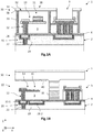
- the Figure 1A illustrates a first example of a detection device 1 which comprises a plurality of thermal detectors 10 each comprising an absorbent membrane 11 suspended above the substrate 2 and electrically connected to a portion 21 of the metal line of the CMOS reading circuit 20, the metallic line hereinafter belonging to a penultimate level of electrical interconnection of the CMOS circuit 20.
- the thermal detectors 10 are made using sacrificial layers of a mineral material identical or similar to that of the inter-metal dielectric layers 23 of the CMOS circuit 20.
- a electrical connection pad 5 is arranged to be able to connect the CMOS circuit 20 from outside the detection device 1.
- An etch stop layer 4 extends continuously over the surface of the substrate 2, so as to block the progression of a chemical etching implemented during the step of removing the mineral sacrificial layers and thus preserve the CMOS circuit 20.
- the thermal detector or detectors 10 are encapsulated in a hermetic cavity 3 partially delimited by an encapsulation layer 31 covered with a sealing layer 34, the latter ensuring in particular the sealing of at least one release vent 32 allowing the evacuation of the etching products during the step of removing the inorganic sacrificial layers.
- the Figure 1B illustrates a second example of detection device 1, the thermal detectors 10 are also made using mineral sacrificial layers.
- An etch stop layer 4 also protects the inter-metal dielectric layers 23 of the CMOS circuit 20 during the step of removing the inorganic sacrificial layers.
- the thermal detector or detectors 10 are encapsulated in a hermetic cavity 3 formed here by an encapsulation structure 30 which takes the form here of an attached cover, assembled to the substrate 2 by means of a hermetic seal 35.
- a layer 40 comprising a getter material is located on a lower surface of the attached cover 30, in order to ensure the gas pumping inside the hermetic cavity 3.
- the step of planarization or chemical mechanical polishing is a step for obtaining a substantially flat surface of the deposited mineral sacrificial layer on which the absorbent membrane is made . It is a matter of applying simultaneously, on the upper surface of the mineral sacrificial layer, a chemical action and a mechanical action.
- the mechanical action is carried out conventionally by a polishing head which applies an abrasive material in rotation against the surface of the mineral layer.
- the getter-effect metal material may be selected from titanium, zirconium, vanadium, chromium, cobalt, iron, manganese, palladium, barium, and / or aluminum.
- the inorganic material may be a material comprising at least silicon oxide or silicon nitride.
- the first chemical etching may be a chemical attack in an acidic medium, preferably with hydrofluoric acid in the vapor phase.
- the second chemical etching may be a dry oxygen plasma etching.
- the getter metal layer can rest and be in contact with an electrically insulating layer of the substrate, or can rest and be in contact with an etching stop layer made of a material capable of stopping the first etching and covering a face superior of the substrate.
- the carbonaceous sacrificial layer may cover the getter metal layer.
- the getter metal layer may comprise several distinct portions, at least a first portion of which is located beneath the absorbent membrane.
- the step of producing the thermal detector may comprise the formation of an encapsulation structure of said thermal detector, the encapsulation structure comprising an encapsulation layer extending around and above said thermal detector so as to define with the substrate the hermetic cavity in which said thermal detector is located, the encapsulation layer comprising at least one through hole, said release vent. Materials removed during the first and second chemical etchings can be discharged through said release vent.
- the encapsulation layer may be formed of at least one material comprising silicon.
- the encapsulation layer may comprise a peripheral wall which extends around said thermal detector, and which is in contact with the getter metal layer.
- the thermal detector may comprise at least one anchoring pillar ensuring the maintenance of the absorbent membrane above the substrate, the anchoring pillar being in contact with the getter metal layer.
- the invention relates to the realization of an electromagnetic radiation detection device 1 adapted to detect infrared radiation or terahertz. It comprises at least one thermal detector 10 intended to be located in a sealed cavity 3, and a layer 40 comprising a getter effect material present on the substrate 2 inside the hermetic cavity 3.
- This getter effect material also called getter material, is a material exposed to the atmosphere of the hermetic cavity 3, and capable of performing gaseous pumping by absorption and / or adsorption.
- This getter material is a metallic material which may be chosen from titanium, zirconium, vanadium, chromium, cobalt, iron, manganese, palladium, barium and / or aluminum, or an alloy thereof. metals such as TiZrV. As mentioned below, the getter metal layer 40 may also be reflective at the wavelengths to be detected, or may be used to improve the grip of certain elements of the detection device 1 to the substrate 2.
- the invention also relates to the deposition and etching of a sacrificial layer 50 called protection layer, able to protect the getter metal layer 40 during a subsequent chemical etching step to remove a mineral sacrificial layer 60A, 60B such as etching in an acidic medium, for example with hydrofluoric acid in the vapor phase.
- protection layer a sacrificial layer 50 called protection layer, able to protect the getter metal layer 40 during a subsequent chemical etching step to remove a mineral sacrificial layer 60A, 60B such as etching in an acidic medium, for example with hydrofluoric acid in the vapor phase.
- This sacrificial protection layer 50 comprises a carbonaceous material, that is to say a material formed of at least one type of chemical species comprising carbon atoms. It can thus be a mineral material such as amorphous carbon, possibly of the DLC type (for Diamond Like Carbon, in English), or an organic material such as polyimide. DLC-type carbon is amorphous carbon with a high degree of hybridisation to sp 3 carbon. Preferably, the carbonaceous material does not comprise silicon, so as to avoid the presence of any residues following the etching step of this layer 50.
- the carbonaceous sacrificial layer 50 comprising or consisting of such a material is thus substantially inert with respect to the subsequent chemical etching to remove the inorganic sacrificial layer 60A, 60B.
- substantially inert it is meant that the carbonaceous material does not substantially react with the acidic medium used during this etching step, or even reacts little so that the carbonaceous sacrificial layer 50 is not etched over its entire thickness at the end of this etching step, the getter metal layer 40 thus remaining preserved from any degradation by the carbonaceous sacrificial layer 50.
- the carbonaceous sacrificial layer 50 may also be suppressed by a chemical etching such as a dry chemical etching of which an etching agent is oxygen contained in a plasma.
- the invention also relates to the deposition and etching of at least one sacrificial layer 60A, 60B comprising a mineral material, or inorganic, called mineral sacrificial layer.
- the mineral material is here a silicon-based dielectric material enabling the production of an inter-metal dielectric layer 23 of the readout circuit 20, that is to say an electrical insulating material, with for example a dielectric constant, or relative permittivity, less than or equal to 3.9, making it possible to limit the parasitic capacitance between the interconnections. It is a material that does not comprise carbon chains, such as an SiOx silicon oxide or an Si x N y silicon nitride, or even an organosilicon material such as SiOC, SiOCH, or a material fluorinated glass type such as SiOF.
- a mineral sacrificial layer 60A, 60B comprising or consisting of such a material may be removed by wet chemical etching such as etching in an acid medium, for example with hydrofluoric acid in the vapor phase.
- wet etching it is generally understood that the etching agent is in the liquid phase or in the vapor phase, and, in the context of the invention, in the vapor phase.
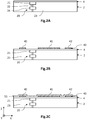
- FIGS. 2A to 2G illustrate different steps of producing a detection device 1 according to a first embodiment.
- steps, apart from the deposition steps of the getter material, deposition and removal of the carbonaceous sacrificial layer 50, may be similar or identical to those of the process described in document EP2743659 .
- a three-dimensional direct reference (X, Y, Z) is defined here and for the rest of the description, in which the plane (X, Y) is substantially parallel to the plane of a substrate 2 of the detection device 1, the Z axis being oriented in a direction substantially orthogonal to the plane of the substrate 2.
- the terms “vertical” and “vertically” extend as being relative to an orientation substantially parallel to the Z axis, and the terms “horizontal” and “horizontally” as being relative to an orientation substantially parallel to the plane (X, Y).
- the terms “lower” and “upper” extend as being relative to an increasing position when moving away from the substrate 2 in the + Z direction.
- a substrate 2 is made comprising a read circuit 20 of the CMOS circuit type.
- the CMOS circuit 20 is able to supply and measure the signal delivered by the thermal detectors 10. It thus comprises active electronic elements, such as diodes, transistors, capacitors, resistors ..., electrically connected by metallic interconnections to the thermal detectors. 10, as well as a connection pad (not shown) for electrically connecting the detection device 1 to an external electronic device.
- the read circuit 20 here comprises an electrical interconnection level comprising a first portion 21 of a metal line, electrically connected to a portion 24 of metal line of a lower level of electrical interconnection by a conductive via 22.
- the vias 22 and metal lines are separated from each other by inter-metal dielectric layers 23.
- the substrate 2 here comprises an upper face at which the portion 21 of the metal line and the inter-metal dielectric layer 23 are flush with.
- This step of embodiment of the substrate 2 may be identical or similar to that described in the document EP2743659 .
- the conductive vias 22 and the portions 21, 24 of metal lines may be made of copper, aluminum or tungsten, by a damascene process. wherein copper is filled with trenches made in the inter-metal dielectric layer 23.
- the copper or tungsten may optionally be interposed transversely between vertical layers of titanium nitride, tantalum or the like.
- the outcropping of the portion of metal line at the upper face of the inter-metal dielectric layer 23 can be obtained by a chemical mechanical polishing (CMP) technique.
- CMP chemical mechanical polishing
- the etching stop layer 4 comprises a material substantially inert with a chemical etching implemented subsequently to remove a carbonaceous sacrificial layer 50, more precisely a chemical dry etching with oxygen plasma. This material may also be substantially inert to a subsequent chemical etching to remove the inorganic sacrificial layer (s) 60A, 60B, more precisely a chemical etching in a vapor phase HF medium, in the case where the carbonaceous sacrificial layer 50 does not It does not completely cover the upper face of the substrate 2.
- the etch stop layer 4 thus makes it possible to prevent the inter-metal dielectric layers 23 of the CMOS circuit 20 from being etched during the steps of removing the sacrificial layers. It may be formed from Al 2 O 3 alumina, or even aluminum nitride, aluminum trifluoride, or unintentionally doped amorphous silicon. It can be deposited for example by ALD ( Atomic Layer Deposition, in English) and have a thickness for example of the order of ten nanometers to a few hundred nanometers, for example a thickness between 20nm and 150nm.
- ALD Atomic Layer Deposition
- a getter metal layer 40 is deposited on the etch stop layer 4.
- This layer comprises a metallic material adapted to ensure a getter effect, that is to say to pump, by absorption and / or adsorption. , the gas molecules present in the hermetic cavity 3.
- This getter effect makes it possible to improve or maintain a required level of vacuum in the hermetic cavity 3.
- This material is also substantially inert to a subsequent chemical etching to remove the layer.
- carbonaceous sacrificial 50 more precisely here a dry chemical etching by oxygen plasma.
- the metallic material is based on titanium, zirconium, vanadium, chromium, cobalt, iron, manganese, palladium, and / or aluminum, that is to say it comprises the one of these metals or an alloy of these metals, such as TiZrV.
- titanium, zirconium, palladium and vanadium, and their alloys have high chemisorption properties (getter effect).
- the material can be deposited by standard techniques of microelectronics, for example by cathodic sputtering, by vacuum evaporation or by chemical phase deposition.
- the getter metal layer 40 may have a thickness of the order of a few tens of nanometers to a few hundred nanometers, for example a thickness of between 50 nm and 500 nm, or even between 100 nm and 300 nm.
- the getter metal layer 40 may be made of the same material or of several of the abovementioned materials. It can thus be formed of a stack of several so-called elementary layers, for example a bottom layer of 50 nm of titanium, an intermediate layer of 100 nm of aluminum and a top layer of 200 nm of titanium.
- the getter metal layer 40 being made of one or more of said metallic materials, it can also provide, when it is located opposite the absorbent membrane 11, an optical reflection function of the wavelengths to be detected, thereby improving the sensitivity of the thermal detector 10.
- the getter metal layer 40 may furthermore provide an additional grip function making it possible to improve the adhesion of elements of the detection device 1 on the substrate 2. Titanium and chromium thus present, among the list of the aforementioned materials, high adhesion properties.
- the getter metal layer 40 here extends discontinuously and comprises distinct portions from each other, obtained by conventional photolithography and etching operations.
- a first portion 41 has a large area, for example of the order of the pixel, possibly in the form of a rectangle or a square, favoring the getter function of chemical trapping of gas molecules.
- the first portion 41 advantageously extends under the absorbent membrane 11 so as to form a quarter-wave interference cavity with the latter, improving the sensitivity of the thermal detector 10.
- a second portion 42 may advantageously be made in an area where an element of the detection device 1 will be produced, the adhesion of which to the substrate 2 will thus be reinforced by the quality of grip that the getter metal layer 40 provides. It can thus be located on the edge of the cavity 3, so as to receive the peripheral wall 33 of the encapsulation layer 31 which will subsequently be produced.
- a third portion can advantageously be made at the portion 21 of the metal line and in an area where the pillar will be made anchoring 12 of the thermal detector 10.
- the anchoring pillar 12 can thus be in contact with the third getter metal layer portion 40, the latter preferably being directly in contact with the portion 21 of metal line. This improves the quality of the electrical contact between the CMOS reading circuit 20 and the anchor pillar 12, and the attachment of the anchor pillar on the substrate.
- This third portion is particularly advantageous when the etch stop layer 4 is not present, as described below with reference to the figure 3 .
- a sacrificial protective layer called the carbonaceous sacrificial layer 50, is then deposited so as to entirely cover the getter metal layer 40.
- the latter does not comprise a free surface, that is to say a surface accessible to a engraving agent.
- the carbonaceous sacrificial layer 50 comprises a carbonaceous material that can be etched selectively with respect to the getter metal layer 40, that is to say that it can be removed during a chemical etching step implemented. subsequently, more precisely here a dry chemical etching by oxygen plasma, without the getter metal layer 40 is degraded by this same chemical etching. It is also substantially inert with respect to another chemical etching carried out subsequently to remove inorganic sacrificial layers 60A, 60B, such as etching in an acid medium, for example with hydrofluoric acid in the vapor phase.
- the carbonaceous material that is to say a material comprising carbon atoms, is preferably chosen from amorphous carbon, possibly of the DLC type, or even the polyimide.
- the carbonaceous sacrificial layer 50 may have an electrical resistivity of the order of 10 6 ⁇ .cm, which is advantageous for avoiding parasitic electrical coupling between two anchoring pillars 12 of a same thermal detector 10, when they are brought to different electrical potentials during an electrical test phase, these anchoring pillars 12 being in contact with the same carbonaceous sacrificial layer 50.
- the carbonaceous material when it is amorphous carbon, can be deposited in a thin layer by a conformal deposition technique, such as plasma enhanced chemical vapor deposition (PECVD) for Plasma Enhanced Chemical Vapor Deposition. ), or physical vapor deposition (PVD), for Physical Vapor Deposition, in English) eg by sputtering an ion beam carbon target (IBS).
- PECVD plasma enhanced chemical vapor deposition
- PVD physical vapor deposition
- IBS ion beam carbon target
- polyimide it can be deposited by dispensing and then centrifugation ( spin coating ).
- the sacrificial carbonaceous layer 50 has a thickness of between a few tens of nanometers to a few hundred nanometers, for example between 50 nm and 500 nm, or even between 100 nm and 300 nm, so as to obtain a good recovery of the sides of the portions 41 , 42 of getter material.
- the carbonaceous material is thus inert with respect to an etching agent used during the chemical etching carried out subsequently to remove the inorganic sacrificial layers 60A, 60B, in particular hydrofluoric acid in the vapor phase.
- an etching agent used during the chemical etching carried out subsequently to remove the inorganic sacrificial layers 60A, 60B, in particular hydrofluoric acid in the vapor phase.
- This is particularly the case of amorphous carbon which does not react substantially with this etching agent.
- polyimide which reacts little with hydrofluoric acid, so that it is not removed throughout its thickness at the end of this wet chemical etching step, the metal getter layer 40 thus remaining completely covered by a non-zero thickness of the carbonaceous sacrificial layer 50.
- the carbonaceous material is, however, capable of reacting with an etching agent used during the chemical etching carried out subsequently to eliminate this carbonaceous sacrificial layer 50, in particular vis-à-vis oxygen present in a plasma of carbon dioxide. a dry chemical etching.
- a first so-called mineral sacrificial layer is then deposited comprising a mineral material, for example an SiO x silicon oxide deposited by PECVD.
- This mineral material is capable of being removed by wet chemical etching, in particular by etching in an acid medium, the etching agent preferably being hydrofluoric acid in the vapor phase.
- This inorganic sacrificial layer 60A is deposited so as to extend continuously over substantially the entire surface of the substrate 2 and to cover the carbonaceous sacrificial layer 50. It has a thickness, along the Z axis, which subsequently defines the distance separating the absorbent membrane 11 of the substrate 2.
- This thickness is adjusted according to the absorption properties of the thermal detector 10 that is desired, and may be between 1 .mu.m and 5 .mu.m for the detection of infrared radiation, for example it may be equal to 2 .mu.m about.
- Vertical orifices for the formation of the anchoring pillars 12 of the thermal detector 10 are then produced. They are produced by photolithography and etching, and pass through the first mineral sacrificial layer 60A as well as the carbonaceous sacrificial layer 50 as well as the etching stop 4, to lead to the portion 21 of metal line. Vertical holes may have a cross section in the plane (X, Y) of square, rectangular or circular shape, with a surface substantially equal to, for example, 0.25 ⁇ m 2 .
- the anchoring pillars 12 are then made in the vertical orifices. They can be made by filling the orifices with one or more electrically conductive materials. For example, they may each comprise a layer of TiN deposited by MOCVD (for Metal Organic Chemical Vapor Deposition, in English) on the vertical sides of the orifices, and a copper or tungsten core filling the space delimited transversely by the TiN layer.
- MOCVD Metal Organic Chemical Vapor Deposition, in English
- a step of CMP that is to say, chemical-mechanical planarization, then allows to planarize the upper surface formed by the mineral sacrificial layer 60A and by the anchoring pillars 12.
- the inventors have found that the mechanical strength of the inorganic sacrificial layer 60A during the mechano-chemical planarization step is improved when the latter rests on the amorphous carbon protection layer 50.
- the protective layer 50 is made of polyimide
- the mechano-chemical planarization step can lead to a detachment of the mineral sacrificial layer 60A, in particular because of the mechanical action of the polishing head on the layer. 60A.
- the risks of such detachment occurring during the CMP stage are decreased when the protective layer 50 is amorphous carbon, in particular when the mineral sacrificial layer 60A is made of an SiO x silicon oxide.
- the absorbent membrane 11 and the arm 13 for holding and thermal insulation are produced.
- This step can be performed in the same or similar manner as described in the document EP2743659 and is not repeated in detail.
- the absorbent membrane 11 may comprise a material 15 adapted to absorb the electromagnetic radiation of interest and a thermistor material 14 whose electrical conductivity varies as a function of the heating of the absorbent membrane 11.
- the materials chosen to produce the absorbent membrane 11 and the heat-insulating arm 13 can be chosen, among others, from amorphous silicon, titanium nitride, aluminum, alumina, aluminum nitride, insofar as they are substantially inert to the wet chemical etching performed subsequently to remove the inorganic sacrificial layers 60A, 60B.
- the absorbent membrane 11 is positioned so as to face the first reflective portion 41 of the getter metal layer 40.
- the encapsulation structure 30 is produced in the same or similar manner as described in the document EP2743659 .
- a second inorganic sacrificial layer 60B is deposited on the first inorganic sacrificial layer 60A, the anchoring pillars 12 and the heat-insulating arms 13, as well as on the absorbent membrane 11. It may be made of the same material as that of the first mineral sacrificial layer 60A and has a thickness for example between 0.5 ⁇ m and 5 ⁇ m.
- Trenches are then made through the entire thickness of the mineral sacrificial layers 60A, 60B and the carbonaceous sacrificial layer 50 so as to lead, in this embodiment, to the second attachment portions 42 of the getter metal layer. 40.
- These trenches can be made by photolithography and etching steps, for example RIE etching. They can be made to extend continuously around one or more thermal detectors 10 in the (X, Y) plane, depending on whether the cavity 3 houses one or more pixels each comprising a thermal detector 10. They are intended for the subsequent realization of the peripheral wall 33 of the encapsulation structure 30.
- the attachment portions 42 of the getter metal layer 40 form here etch stop portions during the formation of these trenches.
- a thin encapsulation layer 31, transparent to the radiation to be detected, is then deposited by a conformal deposition technique adapted to obtain a good overlap of the vertical edges of the trenches with a substantially constant layer thickness.
- It may be for example a layer of amorphous silicon produced by CVD or by iPVD, of a thickness typically between about 200 nm and 2000 nm when measured on a flat surface, and preferably of the order of 750 nm so as to form a quarter-wave plate with respect to a reference wavelength of 10 ⁇ m when the spectral range of detection of the thermal detector is LWIR (8 ⁇ m to 14 ⁇ m), thus improving the transmission of the incident radiation through this layer 31.
- the deposition of the encapsulation layer 31 on a surface structured by trenches including at least one continuous peripheral trench (closed perimeter) leads to the formation of the capsule, made with the material of the encapsulation layer 31, forming, with the substrate 2, a cavity 3 in which are housed one or more thermal detectors 10.
- Through-holes 32 forming release vents intended to allow the sacrificial layers 60A, 60B, 50 to escape from the cavity 3, are then produced by photolithography and etching in the encapsulation layer 31.
- Each vent 32 may be square, rectangular, circular or even oblong.
- the vents 32 may have an oblong shape whose length may be of the order of a few microns, for example 5 ⁇ m, and the width may be of the order of a hundred to a few hundred nanometers, for example be between 150nm and 600nm.
- a first chemical etching is carried out adapted to remove the two mineral sacrificial layers 60A, 60B, here by a wet chemical etching by hydrofluoric acid etching in the vapor phase, and thus to form the cavity 3 housing the thermal detector (s) 10.
- the products of the chemical reaction are evacuated through the release vents 32.
- This wet chemical etching being isotropic, the suspension of the absorbent membrane 11 is obtained, and the anchoring pillars 12 and the upper surface of the layer are released.
- HF etching is selective so that the carbonaceous sacrificial layer 50 is not removed, the getter metal layer 40 then being fully protected from the vapor HF attack.
- a second chemical etching is carried out, which is suitable for removing the carbonaceous sacrificial layer 50 and freeing the upper surface of the getter metal layer 40.
- the chemical etching is a dry chemical etching of which the etching agent is oxygen present in the a plasma. Since this dry etching is isotropic, the integrity of the structures released is preserved while facilitating access to the etching agent in the cavity 3 through the release vents 32.
- the inventors have thus demonstrated that the evacuation of the products of the reaction through the release vents 32 is possible and remains compatible, in terms of etching time and elimination, with the requirements of an industrial implementation.
- the sacrificial layer 50 is formed of amorphous carbon or polyimide.
- the getter metal layer 40 is released, that is to say that it has at least part of its surface not covered by another layer, and thus exposed to the atmosphere of the cavity 3.
- a sealing layer 34 is deposited on the encapsulation layer 31 with a thickness sufficient to seal or plug the release vents 32.
- the sealing layer 34 is transparent to the electromagnetic radiation to be detected and may have a function antireflet to optimize the transmission of radiation through the encapsulation structure 30.
- it may be formed of sublayers of germanium and zinc sulfide in the case of a radiation to be detected in the range wavelengths ranging from 8 .mu.m to 12 .mu.m, for example a first germanium sub-layer of approximately 1.7 .mu.m and then a second sub-layer of zinc sulphide of approximately 1.2 .mu.m.
- the sealing layer 34 is preferably deposited by a technique of deposition of thin layers under vacuum, such as evaporation under vacuum of an electron beam heated source (EBPVD) or as sputtering, cathodic or ion beam.
- EBPVD electron beam heated source
- a sealed cavity 3 is thus obtained under vacuum or reduced pressure in which the thermal detector or detectors 10 are housed.
- the chemisorption of the getter metal layer 40 is further activated by subjecting the detection device 1 to a suitable heat treatment, in an oven or an oven, so as to react the getter material with residual gas molecules present in the cavity. hermetic 3 and thus form stable chemical compounds. This results in a level of vacuum maintained or lowered inside the hermetic cavity 3, thus improving the life of the detection device 1.
- a detection device 1 comprising a getter metal layer 40 located on the substrate 2 and preserved from any degradation. This improves the life of the detection device 1 made using at least one mineral sacrificial layer 60A, 60B.
- the getter metal layer 40 is located under the absorbent membrane 11, this getter metal layer 40 being reflective at the wavelengths to be detected, the sensitivity of the thermal detector 10 is improved, especially as the layer metal getter 40 is not covered with another layer, such as an etch stop layer 4 as in the example of the prior art mentioned above.
- the getter metal layer 40 can also improve the grip of the encapsulation structure 30 on the substrate 2 and / or the grip and the electrical contact of the anchoring pillar 12 with the portion 21 of the metal line of the circuit reading 20.
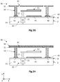
- figure 3 illustrates a variant of the method for producing the detection device 1 in which the detection device does not include an etching stop layer 4.
- figure 3 here is a variant of the step illustrated on the figure 2E .
- the getter metal layer 40 then rests directly on the upper surface of the substrate 2, and the carbonaceous sacrificial layer 50 extends continuously so as to cover the getter metal layer 40 but also the upper face of the substrate 2.
- etching stop function with respect to the chemical etching implemented to remove the inorganic sacrificial layers 60A, 60B, thus protecting both the layer metal getter 40 but also the inter-metal dielectric layers 23 of mineral material present in the substrate 2.
- the getter metal layer 40 comprises an additional portion 43 which rests on the upper surface of the substrate 2 and is arranged to be in contact with the first metal line portion 21 of the read circuit 20 on the one hand, and to ensure the attachment of the anchor pillar 12 on the other hand. This improves the quality of the electrical contact between the reading circuit 20 and the anchoring pillar 12, as well as the anchoring of the anchoring pillar 12 on the substrate 2.
- the production method is continued as described above with wet chemical etching of the inorganic sacrificial layers 60A, 60B ( fig.2F ), then the oxygen plasma dry etching of the carbonaceous sacrificial layer 50 ( fig.2G ), which exposes the areas of the upper face of the substrate 2 not covered by the portions 41, 42, 43 of the getter metal layer 40.
- the sealing layer 34 is finally deposited on the encapsulation layer 31 so as to to close the release vents 32 ( fig.2H ).
- the figure 4 illustrates another embodiment of the detection device 1 which differs from that illustrated on the figure 2H essentially in that the encapsulation structure 30 does not comprise an encapsulation layer 31 deposited by thin layer deposition techniques, but a rigid cover added, that is to say, previously made and then assembled to the substrate 2 of in order to encapsulate one or more thermal detectors 10.
- the cover can be made from a silicon substrate 2 and is structured so as to comprise a peripheral wall 33 intended to be assembled to the substrate 2.
- the peripheral wall 33 is fixed to substrate 2 by means of a hermetic seal 35, the latter being preferably in contact with a portion 42 of attachment of the getter metal layer 40.
- the hermetic seal 35 can be obtained by remelting a fuse metal or by the formation of an intermetallic alloy.
- the method for producing this embodiment differs here from that described with reference to Figures 2A to 2H in that, following the deposition of the first inorganic sacrificial layer 60A and the production of the anchoring pillar 12, the thermal insulation arm 13, the absorbent membrane 11 and the deposition of the second mineral sacrificial layer 60B depositing, in a trench made by localized etching, the mineral sacrificial layers 60a, 60B and the carbonaceous sacrificial layer 50, a sealing material intended to form the hermetic seal 35. Then the mineral sacrificial layers 60A are etched off, 60B then the carbonaceous sacrificial layer 50. The hood is then assembled on the substrate 2.
- the housing made for example of metal materials or ceramic materials, then comprises a transparent window at the wavelengths to be detected and located opposite the thermal detector or detectors 10.
Landscapes
- Physics & Mathematics (AREA)
- Engineering & Computer Science (AREA)
- General Physics & Mathematics (AREA)
- Power Engineering (AREA)
- Computer Hardware Design (AREA)
- Condensed Matter Physics & Semiconductors (AREA)
- Electromagnetism (AREA)
- Microelectronics & Electronic Packaging (AREA)
- Spectroscopy & Molecular Physics (AREA)
- Manufacturing & Machinery (AREA)
- Chemical & Material Sciences (AREA)
- Crystallography & Structural Chemistry (AREA)
- Photometry And Measurement Of Optical Pulse Characteristics (AREA)
- Radiation Pyrometers (AREA)
Abstract
- dépôt, sur le substrat (2), d'une couche métallique dite getter (40) comprenant un matériau métallique à effet getter ;
- dépôt d'une couche sacrificielle dite carbonée (50) en carbone amorphe sur la couche métallique getter (40) ;
- dépôt d'au moins une couche sacrificielle minérale (60A, 60B) sur la couche sacrificielle carbonée (50) ;
- aplanissement mécano-chimique de la couche sacrificielle minérale (60A) ;
- réalisation du détecteur thermique (10) de sorte que la membrane absorbante (11) est réalisée sur la couche sacrificielle minérale (60A) ;
- suppression de la couche sacrificielle minérale (60A, 60B) ;
- suppression de la couche sacrificielle carbonée (50).
Description
- Le domaine de l'invention est celui des dispositifs de détection de rayonnement électromagnétique, en particulier infrarouge ou térahertz, comportant au moins un détecteur thermique encapsulé dans une cavité hermétique, une couche mince d'un matériau getter étant située dans la cavité hermétique. L'invention s'applique notamment au domaine de l'imagerie infrarouge et de la thermographie.
- Un dispositif de détection de rayonnement électromagnétique, par exemple infrarouge ou térahertz, peut comprendre une matrice de détecteurs thermiques, dits élémentaires, chaque détecteur comportant une portion absorbante apte à absorber le rayonnement électromagnétique à détecter.
- Dans le but d'assurer l'isolation thermique des détecteurs thermiques, les portions absorbantes se présentent habituellement sous la forme de membranes suspendues au-dessus du substrat par des piliers d'ancrage, et sont isolées thermiquement de celui-ci par des bras de maintien et d'isolation thermique. Ces piliers d'ancrage et bras d'isolation présentent également une fonction électrique en reliant électriquement les membranes suspendues à un circuit de lecture généralement disposé dans le substrat.
- Le circuit de lecture se présente habituellement sous la forme d'un circuit CMOS. Il permet l'application d'un signal de commande aux détecteurs thermiques ainsi que la lecture de signaux de détection générés par les détecteurs thermiques en réponse à l'absorption du rayonnement électromagnétique à détecter. Le circuit de lecture comporte différents niveaux d'interconnexion électrique formés de lignes métalliques séparées les unes des autres par des couches diélectriques dites inter-métal. Un plot de connexion électrique du circuit de lecture est disposé sur le substrat de telle manière qu'il puisse être contacté depuis l'extérieur du dispositif de détection.
- Le document
EP2743659 décrit ainsi deux exemples de dispositif de détection d'un rayonnement infrarouge, dont le procédé de réalisation utilise des couches sacrificielles minérales identiques ou similaires aux couches diélectriques inter-métal du circuit de lecture. - La
figure 1A illustre un premier exemple de dispositif de détection 1 qui comporte une pluralité de détecteurs thermiques 10 comportant chacun une membrane absorbante 11 suspendue au-dessus du substrat 2 et reliée électriquement à une portion 21 de ligne métallique du circuit de lecture CMOS 20, la ligne métallique appartenant ici à un avant-dernier niveau d'interconnexion électrique du circuit CMOS 20. Les détecteurs thermiques 10 sont réalisés en utilisant des couches sacrificielles en un matériau minéral identique ou similaire à celui des couches diélectriques inter-métal 23 du circuit CMOS 20. Un plot de connexion électrique 5 est agencé de manière à pouvoir connecter le circuit CMOS 20 depuis d'extérieur du dispositif de détection 1. Une couche d'arrêt de gravure 4 s'étend continûment sur la surface du substrat 2, de manière à bloquer la progression d'une gravure chimique mise en oeuvre lors de l'étape de suppression des couches sacrificielles minérales et ainsi préserver le circuit CMOS 20. Le ou les détecteurs thermiques 10 sont encapsulés dans une cavité hermétique 3 en partie délimitée par une couche d'encapsulation 31 recouverte d'une couche de scellement 34, cette dernière assurant notamment l'obturation d'au moins un évent de libération 32 permettant l'évacuation des produits de gravure lors de l'étape de suppression des couches sacrificielles minérales. - La
figure 1B illustre un deuxième exemple de dispositif de détection 1, dont les détecteurs thermiques 10 sont également réalisés en utilisant des couches sacrificielles minérales. Une couche d'arrêt de gravure 4 assure également la protection des couches diélectriques inter-métal 23 du circuit CMOS 20 lors de l'étape de suppression des couches sacrificielles minérales. Une deuxième portion 21-2 de la même ligne métallique que celle de la portion 21-1, située en regard de la membrane absorbante 11 et recouverte par la couche d'arrêt de gravure 4, assure une fonction de réflexion optique des longueurs d'onde à détecter. Le ou les détecteurs thermiques 10 sont encapsulés dans une cavité hermétique 3 formée ici par une structure d'encapsulation 30 qui prend la forme ici d'un capot rapporté, assemblé au substrat 2 au moyen d'un joint hermétique 35. Une couche 40 comportant un matériau getter est située sur une surface inférieure du capot rapporté 30, dans le but d'assurer le pompage gazeux à l'intérieur de la cavité hermétique 3. - Cependant, il existe un besoin de disposer d'un procédé de réalisation d'un dispositif de détection d'un rayonnement électromagnétique, qui comporte l'utilisation d'au moins une couche sacrificielle minérale, et dont une couche en un matériau getter soit déposée sur la surface du substrat, à l'intérieur de la cavité hermétique.
- Il existe également un besoin de disposer d'un tel procédé de réalisation d'un dispositif de détection d'un rayonnement électromagnétique qui autorise la formation d'une couche mince d'encapsulation s'étendant au-dessus et autour du ou des détecteurs thermiques.
- Il existe également un besoin de disposer d'un tel procédé qui permette la réalisation d'un dispositif de détection d'un rayonnement électromagnétique dont la sensibilité de détection est améliorée.
- L'invention a pour objectif de remédier au moins en partie aux inconvénients de l'art antérieur, et plus particulièrement de proposer un procédé de réalisation d'un dispositif de détection de rayonnement électromagnétique comprenant au moins un détecteur thermique, celui-ci comportant une membrane absorbante adaptée à absorber le rayonnement à détecter, suspendue au-dessus d'un substrat, le détecteur thermique étant destiné à être situé dans une cavité hermétique. Le procédé comportant au moins les étapes suivantes :
- dépôt, sur le substrat, d'une couche métallique dite getter comprenant un matériau métallique à effet getter ;
- dépôt, de manière à recouvrir la couche métallique getter, d'une couche sacrificielle dite carbonée comprenant un matériau carboné en carbone amorphe apte à être gravé sélectivement vis-à-vis de la couche métallique getter par une seconde gravure chimique ;
- dépôt, sur la couche sacrificielle carbonée, d'au moins une couche sacrificielle minérale comprenant un matériau minéral apte à être gravé sélectivement vis-à-vis de la couche sacrificielle carbonée par une première gravure chimique ;
- aplanissement mécano-chimique de la couche sacrificielle minérale ;
- réalisation du détecteur thermique de sorte que la membrane absorbante est réalisée sur la couche sacrificielle minérale ;
- suppression de la couche sacrificielle minérale par ladite première gravure chimique ;
- suppression de la couche sacrificielle carbonée par ladite seconde gravure chimique.
- L'étape d'aplanissement ou de polissage mécano-chimique (CMP, pour Chemical Mechanical Polishing/Planarization, en anglais) est une étape permettant d'obtenir une surface sensiblement plane de la couche sacrificielle minérale déposée, sur laquelle la membrane absorbante est réalisée. Il s'agit d'appliquer simultanément, à la surface supérieure de la couche sacrificielle minérale, une action chimique et une action mécanique. L'action mécanique est effectuée classiquement par une tête de polissage qui applique une matière abrasive en rotation contre la surface de la couche minérale.
- Certains aspects préférés, mais non limitatifs de ce dispositif de détection sont les suivants.
- Le matériau métallique à effet getter peut être choisi parmi le titane, le zirconium, le vanadium, le chrome, le cobalt, le fer, le manganèse, le palladium, le baryum, et/ou l'aluminium.
- Le matériau minéral peut être un matériau comportant au moins de l'oxyde de silicium ou du nitrure de silicium.
- La première gravure chimique peut être une attaque chimique en milieu acide, de préférence à l'acide fluorhydrique en phase vapeur.
- La seconde gravure chimique peut être une gravure sèche par plasma d'oxygène.
- La couche métallique getter peut reposer et être au contact d'une couche électriquement isolante du substrat, ou peut reposer et être au contact d'une couche d'arrêt de gravure réalisée en un matériau apte à stopper la première gravure chimique et recouvrant une face supérieure du substrat.
- La couche sacrificielle carbonée peut recouvrir la couche métallique getter.
- La couche métallique getter peut comporter plusieurs portions distinctes, dont au moins une première portion est située sous la membrane absorbante.
- L'étape de réalisation du détecteur thermique peut comporter la formation d'une structure d'encapsulation dudit détecteur thermique, la structure d'encapsulation comportant une couche d'encapsulation s'étendant autour et au-dessus dudit détecteur thermique de manière à définir avec le substrat la cavité hermétique dans laquelle ledit détecteur thermique est situé, la couche d'encapsulation comprenant au moins un orifice traversant, dit évent de libération. Des matériaux supprimés lors des première et deuxième gravures chimiques peuvent être évacués au travers dudit évent de libération.
- La couche d'encapsulation peut être formée en au moins un matériau comportant du silicium.
- La couche d'encapsulation peut comporter une paroi périphérique qui s'étend autour dudit détecteur thermique, et qui est au contact de la couche métallique getter.
- Le détecteur thermique peut comporter au moins un pilier d'ancrage assurant le maintien de la membrane absorbante au-dessus du substrat, le pilier d'ancrage étant au contact de la couche métallique getter.
- D'autres aspects, buts, avantages et caractéristiques de l'invention apparaîtront mieux à la lecture de la description détaillée suivante de formes de réalisation préférées de celle-ci, donnée à titre d'exemple non limitatif, et faite en référence aux dessins annexés, outre les
figures 1A et 1B déjà décrites, sur lesquels : - les
figures 2A à 2H sont des vues schématiques en coupe de différentes étapes d'un procédé de réalisation d'un dispositif de détection selon un premier mode de réalisation ; - la
figure 3 est une vue schématique en coupe d'un dispositif de détection selon un deuxième mode de réalisation ; - la
figure 4 est une vue schématique en coupe d'un dispositif de détection selon un troisième mode de réalisation. - Sur les figures et dans la suite de la description, les mêmes références représentent les éléments identiques ou similaires. De plus, les différents éléments ne sont pas représentés à l'échelle de manière à privilégier la clarté des figures. Par ailleurs, les différents modes de réalisation et variantes ne sont pas exclusifs les uns des autres et peuvent être combinés entre eux. Sauf indication contraire, les termes « sensiblement », « environ », « de l'ordre de » signifient à 10% près.
- L'invention porte sur la réalisation d'un dispositif de détection de rayonnement électromagnétique 1 adapté à détecter un rayonnement infrarouge ou térahertz. Il comporte au moins un détecteur thermique 10 destiné à être situé dans une cavité hermétique 3, et une couche 40 comportant un matériau à effet getter présente sur le substrat 2 à l'intérieur de la cavité hermétique 3. Ce matériau à effet getter, également appelé matériau getter, est un matériau exposé à l'atmosphère de la cavité hermétique 3, et apte à réaliser un pompage gazeux par absorption et/ou adsorption.
- Ce matériau getter est un matériau métallique qui peut être choisi parmi le titane, le zirconium, le vanadium, le chrome, le cobalt, le fer, le manganèse, le palladium, le baryum et/ou l'aluminium, voire un alliage de ces métaux tel que le TiZrV. Comme mentionné plus loin, la couche métallique getter 40 peut également être réflectrice aux longueurs d'onde à détecter, voire peut être utilisée pour améliorer l'accroche de certains éléments du dispositif de détection 1 au substrat 2.
- L'invention porte également sur le dépôt puis la gravure d'une couche sacrificielle 50 dite de protection, apte à protéger la couche métallique getter 40 lors d'une étape de gravure chimique mise en oeuvre ultérieurement pour supprimer une couche sacrificielle minérale 60A, 60B, telle qu'une attaque chimique en milieu acide, par exemple à l'acide fluorhydrique en phase vapeur.
- Cette couche sacrificielle de protection 50 comporte un matériau carboné, c'est-à-dire un matériau formé d'au moins un type d'espèce chimique comportant des atomes de carbones. Il peut ainsi s'agir d'un matériau minéral tel que du carbone amorphe, éventuellement de type DLC (pour Diamond Like Carbon, en anglais), ou un matériau organique tel que du polyimide. Le carbone de type DLC est du carbone amorphe à fort taux d'hybridation en carbone sp3. De préférence, le matériau carboné ne comporte pas de silicium, de manière à éviter la présence d'éventuels résidus à la suite de l'étape de gravure de cette couche 50.
- La couche sacrificielle carbonée 50 comportant, ou constituée d'un tel matériau, est ainsi sensiblement inerte vis-à-vis de la gravure chimique effectuée ultérieurement pour supprimer la couche sacrificielle minérale 60A, 60B. Par sensiblement inerte, on entend que le matériau carboné ne réagit sensiblement pas avec le milieu acide utilisé lors de cette étape de gravure, voire réagit peu de sorte que la couche sacrificielle carbonée 50 n'est pas gravée sur toute son épaisseur à l'issue de cette étape de gravure, la couche métallique getter 40 restant ainsi préservée de toute dégradation par la couche sacrificielle carbonée 50.
- La couche sacrificielle carbonée 50 peut en outre être supprimée par une gravure chimique telle qu'une gravure chimique sèche dont un agent de gravure est de l'oxygène contenu dans un plasma.
- L'invention porte également sur le dépôt puis la gravure d'au moins une couche sacrificielle 60A, 60B comportant un matériau minéral, ou inorganique, dite couche sacrificielle minérale.
- Le matériau minéral est ici un matériau diélectrique à base de silicium permettant la réalisation d'une couche diélectrique inter-métal 23 du circuit de lecture 20, c'est-à-dire un matériau isolant électrique, avec par exemple une constante diélectrique, ou permittivité relative, inférieure ou égale à 3,9, permettant de limiter la capacité parasite entre les interconnexions. Il s'agit d'un matériau ne comportant pas de chaînes carbonées, tel qu'un oxyde de silicium SiOx ou un nitrure de silicium SixNy, voire un matériau organosilicié tel que du SiOC, du SiOCH, ou d'un matériau de type verre fluoré tel que du SiOF.
- Une couche sacrificielle minérale 60A, 60B comportant, ou constituée d'un tel matériau, peut être supprimée par une gravure chimique humide telle qu'une attaque chimique en milieu acide, par exemple à l'acide fluorhydrique en phase vapeur. Par gravure humide, on entend d'une manière générale que l'agent de gravure se présente en phase liquide ou en phase vapeur, et, dans le cadre de l'invention, en phase vapeur.
- Les
figures 2A à 2G illustrent différentes étapes de réalisation d'un dispositif de détection 1 selon un premier mode de réalisation. Plusieurs étapes, hormis les étapes de dépôt du matériau getter, de dépôt et de suppression de la couche sacrificielle carbonée 50, peuvent être similaires ou identiques à celles du procédé décrit dans le documentEP2743659 . - On définit ici et pour la suite de la description un repère direct tridimensionnel (X,Y,Z), où le plan (X,Y) est sensiblement parallèle au plan d'un substrat 2 du dispositif de détection 1, l'axe Z étant orienté suivant une direction sensiblement orthogonale au plan du substrat 2. Les termes « vertical » et « verticalement » s'étendent comme étant relatifs à une orientation sensiblement parallèle à l'axe Z, et les termes « horizontal » et « horizontalement » comme étant relatifs à une orientation sensiblement parallèle au plan (X,Y). Par ailleurs, les termes « inférieur » et « supérieur » s'étendent comme étant relatifs à un positionnement croissant lorsqu'on s'éloigne du substrat 2 suivant la direction +Z.
- En référence à la
figure 2A , on réalise un substrat 2 comportant un circuit de lecture 20 de type circuit CMOS. Le circuit CMOS 20 est apte à alimenter et mesurer le signal délivré par les détecteurs thermiques 10. Il comporte ainsi des éléments électroniques actifs, tels que des diodes, transistors, condensateurs, résistances..., connectés électriquement par des interconnections métalliques aux détecteurs thermiques 10, ainsi qu'à un plot de connexion (non représenté) destiné à relier électriquement le dispositif de détection 1 à un dispositif électronique externe. Le circuit de lecture 20 comporte ici un niveau d'interconnexion électrique comportant une première portion 21 d'une ligne métallique, électriquement reliée à une portion 24 de ligne métallique d'un niveau inférieur d'interconnexion électrique par un via conducteur 22. Les vias 22 et lignes métalliques sont séparés les uns des autres par des couches diélectriques inter-métal 23. Le substrat 2 comporte ici une face supérieure au niveau de laquelle affleurent la portion 21 de ligne métallique ainsi que la couche diélectrique inter-métal 23. Cette étape de réalisation du substrat 2 peut être identique ou similaire à celle décrite dans le documentEP2743659 . Ainsi, à titre illustratif, les vias conducteurs 22 et les portions 21, 24 de lignes métalliques peuvent être réalisés en cuivre, en aluminium ou en tungstène, par un procédé damascène dans lequel on remplit avec du cuivre des tranchées réalisées dans la couche diélectrique inter-métal 23. Le cuivre ou le tungstène peut éventuellement être intercalé transversalement entre des couches verticales en nitrure de titane, de tantale ou autre. L'affleurement de la portion de ligne métallique au niveau de la face supérieure de la couche diélectrique inter-métal 23 peut être obtenu par une technique de polissage mécano-chimique (CMP). - On dépose, sur au moins une partie de la face supérieure du substrat 2, une couche d'arrêt de gravure 4. Celle-ci recouvre ainsi continûment la couche diélectrique inter-métal 23 et la portion 21 de ligne métallique qui forment ensemble la face supérieure du substrat 2. La couche d'arrêt de gravure 4 comporte un matériau sensiblement inerte à une gravure chimique mise en oeuvre ultérieurement pour supprimer une couche sacrificielle carbonée 50, plus précisément une gravure chimique sèche à plasma d'oxygène. Ce matériau peut en outre être sensiblement inerte à une gravure chimique mise en oeuvre ultérieurement pour supprimer la ou les couches sacrificielles minérales 60A, 60B, plus précisément une attaque chimique en milieu HF en phase vapeur, dans le cas où la couche sacrificielle carbonée 50 ne recouvrirait pas entièrement la face supérieure du substrat 2. La couche d'arrêt de gravure 4 permet ainsi d'éviter que les couches diélectriques inter-métal 23 du circuit CMOS 20 ne soient gravées lors des étapes de suppression des couches sacrificielles. Elle peut être formée d'alumine Al2O3, voire de nitrure d'aluminium, de trifluorure d'aluminium, ou de silicium amorphe non intentionnellement dopé. Elle peut être déposée par exemple par ALD (pour Atomic Layer Deposition, en anglais) et présenter une épaisseur par exemple de l'ordre d'une dizaine de nanomètres à quelques centaines de nanomètres, par exemple une épaisseur comprise entre 20nm et 150nm.
- En référence à la
figure 2B , on dépose ensuite, sur la couche d'arrêt de gravure 4, une couche métallique getter 40. Cette couche comporte un matériau métallique adapté à assurer un effet getter, c'est-à-dire à pomper, par absorption et/ou adsorption, les molécules de gaz présentes dans la cavité hermétique 3. Cet effet getter permet d'améliorer ou de maintenir un niveau de vide requis dans la cavité hermétique 3. Ce matériau est en outre sensiblement inerte à une gravure chimique effectuée ultérieurement pour supprimer la couche sacrificielle carbonée 50, plus précisément ici une gravure chimique sèche par plasma d'oxygène. Le matériau métallique est à base de titane, de zirconium, de vanadium, de chrome, de cobalt, de fer, de manganèse, de palladium, et/ou d'aluminium, c'est-à-dire qu'il comporte l'un de ces métaux ou un alliage de ces métaux, tel que le TiZrV. Parmi ces métaux, le titane, le zirconium, le palladium et le vanadium, et leurs alliages, présentent des propriétés élevées de chimisorption (effet getter). Le matériau peut être déposé par les techniques standards de la microélectronique, par exemple par pulvérisation cathodique, par évaporation sous vide ou par dépôt chimique en phase valeur. La couche métallique getter 40 peut présenter une épaisseur de l'ordre de quelques dizaines de nanomètres à quelques centaines de nanomètres, par exemple une épaisseur comprise entre 50nm et 500nm, voire comprise entre 100nm et 300nm. - La couche métallique getter 40 peut être constituée d'un même matériau ou de plusieurs matériaux parmi les matériaux susmentionnés. Elle peut ainsi être formée d'un empilement de plusieurs couches dites élémentaires, par exemple une couche inférieure de 50nm de titane, une couche intermédiaire de 100nm d'aluminium et une couche supérieure de 200nm de titane.
- La couche métallique getter 40 étant réalisée en un ou plusieurs desdits matériaux métalliques, elle peut également assurer, lorsqu'elle est située en regard de la membrane absorbante 11, une fonction de réflexion optique des longueurs d'onde destinées à être détectées, améliorant ainsi la sensibilité du détecteur thermique 10.
- La couche métallique getter 40 peut en outre assurer une fonction supplémentaire d'accroche permettant d'améliorer l'adhérence d'éléments du dispositif de détection 1 sur le substrat 2. Le titane et le chrome présentent ainsi, parmi la liste des matériaux susmentionnés, des propriétés d'adhérence élevées.
- La couche métallique getter 40 s'étend ici de manière discontinue et comportent des portions distinctes les unes des autres, obtenues par des opérations classiques de photolithographie et de gravure.
- Ainsi, une première portion 41 présente une surface importante, par exemple de l'ordre du pixel, éventuellement en forme de rectangle ou de carré, favorisant la fonction getter de piégeage chimique de molécules de gaz. La première portion 41 s'étend avantageusement sous la membrane absorbante 11 de manière à former une cavité interférentielle quart d'onde avec cette dernière, améliorant la sensibilité du détecteur thermique 10.
- Une deuxième portion 42 peut avantageusement être réalisée dans une zone où sera réalisé un élément du dispositif de détection 1 dont l'adhérence au substrat 2 sera ainsi renforcée par la qualité d'accroche qu'offre la couche métallique getter 40. Elle peut ainsi être située en bordure de la cavité 3, de manière à recevoir la paroi périphérique 33 de la couche d'encapsulation 31 qui sera ultérieurement réalisée.
- Une troisième portion (non représentée) peut avantageusement être réalisée au niveau de la portion 21 de la ligne métallique et dans une zone où sera réalisé le pilier d'ancrage 12 du détecteur thermique 10. Le pilier d'ancrage 12 pourra ainsi être au contact de la troisième portion de couche métallique getter 40, cette dernière étant de préférence directement au contact de la portion 21 de ligne métallique. On améliore ainsi la qualité du contact électrique entre le circuit de lecture CMOS 20 et le pilier d'ancrage 12, ainsi que l'accroche du pilier d'ancrage sur le substrat. Cette troisième portion est particulièrement avantageuse lorsque la couche d'arrêt de gravure 4 n'est pas présente, comme décrit plus loin en référence à la
figure 3 . - En référence à la
figure 2C , on dépose ensuite une couche sacrificielle de protection, dite couche sacrificielle carbonée 50, de manière à recouvrir entièrement la couche métallique getter 40. Ainsi, cette dernière ne comporte pas de surface libre, c'est-à-dire une surface accessible à un agent de gravure. - La couche sacrificielle carbonée 50 comporte un matériau carboné apte à être gravé sélectivement vis-à-vis de la couche métallique getter 40, c'est-à-dire qu'il peut être supprimé lors d'une étape de gravure chimique mise en oeuvre ultérieurement, plus précisément ici une gravure chimique sèche par plasma d'oxygène, sans que la couche métallique getter 40 ne soit dégradée par cette même gravure chimique. Il est en outre sensiblement inerte vis-à-vis d'une autre gravure chimique effectuée ultérieurement pour supprimer des couches sacrificielles minérales 60A, 60B, telle qu'une attaque chimique en milieu acide, par exemple à l'acide fluorhydrique en phase vapeur.
- Le matériau carboné, c'est-à-dire un matériau comportant des atomes de carbone, est choisi de préférence parmi le carbone amorphe, éventuellement de type DLC, voire le polyimide. Dans le cas du carbone de type DLC, la couche sacrificielle carbonée 50 peut présenter une résistivité électrique de l'ordre de 106Ω.cm, ce qui est avantageux pour éviter le couplage électrique parasite entre deux piliers d'ancrage 12 d'un même détecteur thermique 10, lorsqu'ils sont portés à des potentiels électriques différents lors d'une phase de test électrique, ces piliers d'ancrage 12 étant en contact avec la même couche sacrificielle carbonée 50. En variante (non représentée), il est possible d'effectuer une gravure localisée de la couche sacrificielle carbonée 50 pour évitertout couplage électrique parasite entre les piliers d'ancrage 12 d'un même détecteur thermique 10 via cette couche sacrificielle carbonée 50.
- Le matériau carboné, lorsqu'il s'agit de carbone amorphe, peut être déposé en couche mince par une technique de dépôt conforme, tel que le dépôt chimique en phase vapeur assistée par plasma (PECVD, pour Plasma Enhanced Chemical Vapor Deposition, en anglais), ou le dépôt physique en phase vapeur (PVD, pour Physical Vapor Deposition, en anglais) par exemple via la pulvérisation d'une cible carbone par faisceau d'ions (IBS). Dans le cas du polyimide, il peut être déposé par dispense puis centrifugation (spin coating).
- La couche sacrificielle carbonée 50 présente une épaisseur comprise entre quelques dizaines de nanomètres à quelques centaines de nanomètres, par exemple comprise entre 50 nm et 500nm, voire comprise entre 100 nm et 300 nm, de manière à obtenir un bon recouvrement des flancs des portions 41, 42 de matériau getter.
- Le matériau carboné est ainsi inerte vis-à-vis d'un agent de gravure utilisé lors de la gravure chimique effectuée ultérieurement pour supprimer les couches sacrificielles minérales 60A, 60B, en particulier l'acide fluorhydrique en phase vapeur. C'est le cas notamment du carbone amorphe qui ne réagit sensiblement pas avec cet agent de gravure. C'est le cas également du polyimide qui réagit peu avec l'acide fluorhydrique, de sorte qu'il n'est pas supprimé sur toute son épaisseur à l'issue de cette étape de gravure chimique humide, la couche métallique getter 40 restant ainsi entièrement recouverte par une épaisseur non nulle de la couche sacrificielle carbonée 50.
- Le matériau carboné est cependant apte à réagir vis-à-vis d'un agent de gravure utilisé lors de la gravure chimique effectuée ultérieurement pour supprimer cette couche sacrificielle carbonée 50, en particulier vis-à-vis d'oxygène présent dans un plasma d'une gravure chimique sèche.
- En référence à la
figure 2D , on dépose ensuite une première couche sacrificielle dite minérale comprenant un matériau minéral, par exemple un oxyde de silicium SiOx déposé par PECVD. Ce matériau minéral est apte à être supprimé par gravure chimique humide, en particulier par attaque chimique en milieu acide, l'agent de gravure étant de préférence de l'acide fluorhydrique en phase vapeur. Cette couche sacrificielle minérale 60A est déposée de manière à s'étendre continûment sur sensiblement toute la surface du substrat 2 et recouvrir la couche sacrificielle carbonée 50. Elle présente une épaisseur, suivant l'axe Z, qui définit ultérieurement la distance séparant la membrane absorbante 11 du substrat 2. Cette épaisseur est ajustée en fonction des propriétés d'absorption du détecteur thermique 10 que l'on souhaite obtenir, et peut être comprise entre 1µm et 5µm pour la détection de rayonnement infrarouge, par exemple elle peut être égale à 2µm environ. - On réalise ensuite des orifices verticaux destinés à la formation des piliers d'ancrage 12 du détecteur thermique 10. Ils sont réalisés par photolithographie et gravure, et traversent la première couche sacrificielle minérale 60A ainsi que la couche sacrificielle carbonée 50 ainsi que la couche d'arrêt de gravure 4, pour déboucher sur la portion 21 de ligne métallique. Les orifices verticaux peuvent présenter une section droite dans le plan (X,Y) de forme carrée, rectangulaire, ou circulaire, d'une surface sensiblement égale par exemple à 0,25µm2.
- On réalise ensuite les piliers d'ancrage 12 dans les orifices verticaux. Ils peuvent être réalisés par remplissage des orifices par un ou plusieurs matériaux électriquement conducteurs. A titre d'exemple, ils peuvent comporter chacun une couche de TiN déposée par MOCVD (pour Metal Organic Chemical Vapor Deposition, en anglais) sur les flancs verticaux des orifices, et un coeur en cuivre ou en tungstène remplissant l'espace délimité transversalement par la couche de TiN. Une étape de CMP, c'est-à-dire d'aplanissement mécano-chimique, permet ensuite de planariser la surface supérieure formée par la couche sacrificielle minérale 60A et par les piliers d'ancrage 12.
- Les inventeurs ont constaté que la tenue mécanique de la couche sacrificielle minérale 60A lors de l'étape d'aplanissement mécano-chimique est améliorée lorsque cette dernière repose sur la couche de protection 50 en carbone amorphe. En effet, lorsque la couche de protection 50 est en polyimide, l'étape d'aplanissement mécano-chimique peut conduire à un décollement de la couche sacrificielle minérale 60A, notamment du fait de l'action mécanique de la tête de polissage sur la couche 60A. Les risques qu'un tel décollement ait lieu lors de l'étape de CMP sont diminués lorsque la couche de protection 50 est en carbone amorphe, en particulier lorsque la couche sacrificielle minérale 60A est réalisée en un oxyde de silicium SiOx.
- On réalise ensuite la membrane absorbante 11 ainsi que le bras 13 de maintien et d'isolation thermique. Cette étape peut être effectuée de manière identique ou similaire à celle décrite dans le document
EP2743659 et n'est pas reprise en détail. Ainsi, la membrane absorbante 11 peut comporter un matériau 15 adapté à absorber le rayonnement électromagnétique d'intérêt et un matériau thermistance 14 dont la conductivité électrique varie en fonction de l'échauffement de la membrane absorbante 11. Les matériaux choisis pour réaliser la membrane absorbante 11 et le bras d'isolation thermique 13 peuvent être choisis, entre autres, parmi le silicium amorphe, le nitrure de titane, l'aluminium, l'alumine, le nitrure d'aluminium, dans la mesure où ils sont sensiblement inertes à la gravure chimique humide effectuée ultérieurement pour supprimer les couches sacrificielles minérales 60A, 60B. La membrane absorbante 11 est positionnée de manière à être en regard de la première portion réflectrice 41 de la couche métallique getter 40. - En référence à la
figure 2E , on réalise la structure d'encapsulation 30 de manière identique ou similaire à celle décrite dans le documentEP2743659 . Pour cela, on dépose une deuxième couche sacrificielle minérale 60B sur la première couche sacrificielle minérale 60A, les piliers d'ancrage 12 et les bras d'isolation thermique 13, ainsi que sur la membrane absorbante 11. Elle peut être réalisée dans le même matériau que celui de la première couche sacrificielle minérale 60A et présente une épaisseur par exemple comprise entre 0,5µm et 5µm. - On réalise ensuite des tranchées au travers de toute l'épaisseur des couches sacrificielles minérales 60A, 60B et de la couche sacrificielle carbonée 50 de manière à déboucher, dans ce mode de réalisation, sur les deuxièmes portions d'accroche 42 de la couche métallique getter 40. Ces tranchées peuvent être réalisée par des étapes de photolithographie et de gravure, par exemple de gravure RIE. Elles peuvent être réalisées de manière à s'étendre de manière continue autour d'un ou plusieurs détecteurs thermiques 10 dans le plan (X,Y), selon que la cavité 3 loge un ou plusieurs pixels comportant chacun un détecteur thermique 10. Elles sont destinées à la réalisation ultérieure de la paroi périphérique 33 de la structure d'encapsulation 30. Les portions d'accroche 42 de la couche métallique getter 40 forment ici des portions d'arrêt de gravure lors de la formation de ces tranchées.
- On dépose ensuite une couche mince d'encapsulation 31, transparente au rayonnement à détecter, par une technique de dépôt conforme adaptée pour obtenir un bon recouvrement des flancs verticaux des tranchées, avec une épaisseur de couche sensiblement constante. Il peut s'agir par exemple d'une couche de silicium amorphe élaboré par CVD ou par iPVD, d'une épaisseur typiquement comprise entre environ 200nm et 2000nm lorsqu'elle est mesurée sur une surface plane, et de préférence de l'ordre de 750nm de manière à former une lame quart d'onde vis-à-vis d'une longueur d'onde de référence de 10µm lorsque le domaine spectral de détection du détecteur thermique est le LWIR (8µm à 14µm), améliorant ainsi la transmission du rayonnement incident au travers de cette couche 31. Le dépôt de la couche d'encapsulation 31 sur une surface structurée par des tranchées dont au moins une tranchée périphérique continue (périmètre fermé) conduit à la formation de la capsule, réalisée avec le matériau de la couche d'encapsulation 31, formant, avec le substrat 2, une cavité 3 dans laquelle sont logés un ou plusieurs détecteurs thermiques 10.
- Des orifices traversants 32, formant des évents de libération destinés à permettre l'évacuation des couches sacrificielles 60A, 60B, 50 hors de la cavité 3, sont ensuite réalisés par photolithographie et gravure dans la couche d'encapsulation 31. Chaque évent 32 peut être de forme carrée, rectangulaire, circulaire, voire oblongue. A titre d'exemple, les évents 32 peuvent présenter une forme oblongue dont la longueur peut être de l'ordre de quelques microns, par exemple 5µm, et la largeur peut être de l'ordre d'une centaine à quelques centaines de nanomètres, par exemple être comprise entre 150nm et 600nm.
- En référence à la
figure 2F , on effectue une première gravure chimique adaptée à supprimer les deux couches sacrificielles minérales 60A, 60B, ici par une gravure chimique humide par attaque à l'acide fluorhydrique en phase vapeur, et former ainsi la cavité 3 logeant le ou les détecteurs thermiques 10. Les produits de la réaction chimique sont évacués au travers des évents de libération 32. Cette gravure chimique humide étant isotrope, on obtient la suspension de la membrane absorbante 11, et on libère les piliers d'ancrage 12 ainsi que la surface supérieure de la couche sacrificielle carbonée 50. La gravure par attaque HF vapeur est sélective de sorte que la couche sacrificielle carbonée 50 n'est pas supprimée, la couche métallique getter 40 étant alors entièrement protégée de l'attaque HF vapeur. - En référence à la
figure 2G , on effectue une deuxième gravure chimique adaptée à supprimer la couche sacrificielle carbonée 50 et rendre libre la surface supérieure de la couche métallique getter 40. La gravure chimique est ici une gravure chimique sèche dont l'agent de gravure est de l'oxygène présent dans un plasma. Cette gravure chimique sèche étant isotrope, on préserve l'intégrité des structures libérées tout en facilitant l'accès à l'agent de gravure dans la cavité 3 au travers des évents de libération 32. - Les inventeurs ont ainsi mis en évidence que l'évacuation des produits de la réaction au travers des évents de libération 32 est possible et reste compatible, en termes de temps de gravure et d'élimination, avec les impératifs propres à une mise en oeuvre industrielle, que la couche sacrificielle 50 soit formée de carbone amorphe ou de polyimide.
- Ainsi, la couche métallique getter 40 est libérée, c'est-à-dire qu'elle présente au moins une partie de sa surface non recouverte par une autre couche, et donc exposée à l'atmosphère de la cavité 3.
- En référence à la
figure 2H , on dépose une couche de scellement 34 sur la couche d'encapsulation 31 avec une épaisseur suffisante pour assurer le scellement, ou bouchage, des évents de libération 32. La couche de scellement 34 est transparente au rayonnement électromagnétique à détecter et peut présenter une fonction d'antireflet pour optimiser la transmission du rayonnement au travers de la structure d'encapsulation 30. A ce titre, elle peut être formée de sous-couches de germanium et de sulfure de zinc dans le cas d'un rayonnement à détecter dans la gamme des longueurs d'onde allant de 8µm à 12µm, par exemple une première sous-couche de germanium de 1,7µm environ puis une deuxième sous-couche de sulfure de zinc de 1,2µm environ. La couche de scellement 34 est de préférence déposée par une technique de dépôt de couches minces sous vide, comme l'évaporation sous vide d'une source chauffée par faisceau d'électrons (EBPVD) ou comme la pulvérisation, cathodique ou par faisceau d'ions. On obtient ainsi une cavité hermétique 3 sous vide ou pression réduite dans laquelle sont logés le ou les détecteurs thermiques 10. - On active en outre la chimisorption de la couche métallique getter 40 en soumettant le dispositif de détection 1 à un traitement thermique adéquat, dans un four ou une étuve, de manière à faire réagir le matériau getter avec des molécules de gaz résiduelles présentes dans la cavité hermétique 3 et former ainsi des composés chimiques stables. On obtient ainsi un niveau de vide maintenu ou abaissé à l'intérieur de la cavité hermétique 3, améliorant ainsi la durée de vie du dispositif de détection 1.
- Ainsi, par le dépôt d'une couche métallique getter 40 sur le substrat 2, et sa protection par une couche sacrificielle carbonée 50 vis-à-vis de la gravure chimique mise en oeuvre lors de l'étape de suppression des couches sacrificielles minérales 60A, 60B, on obtient un dispositif de détection 1 comportant une couche métallique getter 40 située sur le substrat 2 et préservée de toute dégradation. On améliore ainsi la durée de vie du dispositif de détection 1 réalisé en utilisant au moins une couche sacrificielle minérale 60A, 60B.
- De plus, dans le cas où la couche métallique getter 40 est située sous la membrane absorbante 11, cette couche métallique getter 40 étant réflectrice aux longueurs d'onde à détecter, la sensibilité du détecteur thermique 10 est améliorée, d'autant que la couche métallique getter 40 n'est pas recouverte d'une autre couche, telle qu'une couche d'arrêt de gravure 4 comme dans l'exemple de l'art antérieur cité précédemment.
- Par ailleurs, la couche métallique getter 40 peut également améliorer l'accroche de la structure d'encapsulation 30 sur le substrat 2 et/ou l'accroche et le contact électrique du pilier d'ancrage 12 avec la portion 21 de ligne métallique du circuit de lecture 20.
- Des modes de réalisation particuliers viennent d'être décrits. Différentes variantes et modifications apparaîtront à l'homme du métier.
- Ainsi, la
figure 3 illustre une variante du procédé de réalisation du dispositif de détection 1 dans laquelle le dispositif de détection ne comporte pas de couche d'arrêt de gravure 4. Lafigure 3 correspond ici une variante de l'étape illustrée sur lafigure 2E . La couche métallique getter 40 repose alors directement sur la surface supérieure du substrat 2, et la couche sacrificielle carbonée 50 s'étend de manière continue de manière à recouvrir la couche métallique getter 40 mais également la face supérieure du substrat 2. Elle assure donc une fonction d'arrêt de gravure vis-à-vis de la gravure chimique mise en oeuvre pour supprimer les couches sacrificielles minérales 60A, 60B, protégeant ainsi à la fois la couche métallique getter 40 mais également les couches diélectriques inter-métal 23 en matériau minéral présentes dans le substrat 2. - Dans cet exemple, la couche métallique getter 40 comporte une portion supplémentaire 43 qui repose sur la surface supérieure du substrat 2 et est disposée de manière à être en contact avec la première portion 21 de ligne métallique du circuit de lecture 20 d'une part, et à assurer l'accroche du pilier d'ancrage 12 d'autre part. On améliore ainsi la qualité du contact électrique entre le circuit de lecture 20 et le pilier d'ancrage 12, ainsi que l'accroche du pilier d'ancrage 12 sur le substrat 2.
- Le procédé de réalisation se poursuit comme décrit précédemment avec la gravure chimique humide des couches sacrificielles minérales 60A, 60B (
fig.2F ), puis la gravure sèche par plasma d'oxygène de la couche sacrificielle carbonée 50 (fig.2G ), ce qui met à nu les zones de la face supérieure du substrat 2 non recouvertes par les portions 41, 42, 43 de la couche métallique getter 40. La couche de scellement 34 est enfin déposée sur la couche d'encapsulation 31 de manière à obturer les évents de libération 32 (fig.2H ). - Par ailleurs, la
figure 4 illustre un autre mode de réalisation du dispositif de détection 1 qui diffère de celui illustré sur lafigure 2H essentiellement en ce que la structure d'encapsulation 30 ne comporte pas une couche d'encapsulation 31 déposée par des techniques de dépôt en couche mince, mais un capot rigide rapporté, c'est-à-dire préalablement réalisé puis assemblé au substrat 2 de manière à encapsuler un ou plusieurs détecteurs thermiques 10. Le capot peut être réalisé à partir d'un substrat 2 en silicium et est structuré de manière à comporter une paroi périphérique 33 destinée à être assemblée au substrat 2. La paroi périphérique 33 est fixée au substrat 2 par l'intermédiaire d'un joint hermétique 35, ce dernier étant de préférence au contact d'une portion 42 d'accroche de la couche métallique getter 40. Le joint hermétique 35 peut être obtenu par la refonte d'un métal fusible ou par la formation d'un alliage intermétallique. - Le procédé de réalisation de ce mode de réalisation diffère ici de celui décrit en référence aux
figures 2A à 2H en ce que, à la suite du dépôt de la première couche sacrificielle minérale 60A et de la réalisation du pilier d'ancrage 12, du bras d'isolation thermique 13, de la membrane absorbante 11 et du dépôt de la deuxième couche sacrificielle minérale 60B, on dépose, dans une tranchée réalisée par une gravure localisée des couches sacrificielles minérales 60a, 60B et de la couche sacrificielle carbonée 50, un matériau de scellement destiné à former le joint hermétique 35. Puis on supprime par gravure les couches sacrificielles minérales 60A, 60B puis la couche sacrificielle carbonée 50. On assemble ensuite le capot sur le substrat 2. - D'autres variantes sont possibles, telles que l'encapsulation du dispositif de détection 1 dans un boîtier logeant ensemble le ou les détecteurs thermiques 10 et le substrat 2. Le boîtier, réalisé par exemple en matériaux métalliques ou en matériaux céramiques, comporte alors une fenêtre transparente aux longueurs d'onde à détecter et située en regard du ou des détecteurs thermiques 10.
Claims (12)
- Procédé de réalisation d'un dispositif de détection (1) de rayonnement électromagnétique comprenant au moins un détecteur thermique (10), celui-ci comportant une membrane absorbante (11) adaptée à absorber le rayonnement à détecter, suspendue au-dessus d'un substrat (2), le détecteur thermique étant destiné à être situé dans une cavité hermétique (3), le procédé comportant au moins les étapes suivantes :- dépôt, sur le substrat (2), d'une couche métallique dite getter (40) comprenant un matériau métallique à effet getter ;- dépôt, de manière à recouvrir la couche métallique getter (40), d'une couche sacrificielle dite carbonée (50) comprenant un matériau carboné en carbone amorphe apte à être gravé sélectivement vis-à-vis de la couche métallique getter (40) par une seconde gravure chimique ;- dépôt, sur la couche sacrificielle carbonée (50), d'au moins une couche sacrificielle minérale (60A, 60B) comprenant un matériau minéral apte à être gravé sélectivement vis-à-vis de la couche sacrificielle carbonée (50) par une première gravure chimique ;- aplanissement mécano-chimique de la couche sacrificielle minérale (60A) ;- réalisation du détecteur thermique (10) de sorte que la membrane absorbante (11) est réalisée sur la couche sacrificielle minérale (60A) ;- suppression de la couche sacrificielle minérale (60A, 60B) par ladite première gravure chimique ;- suppression de la couche sacrificielle carbonée (50) par ladite seconde gravure chimique.
- Procédé selon la revendication 1, dans lequel le matériau métallique à effet getter est choisi parmi le titane, le zirconium, le vanadium, le chrome, le cobalt, le fer, le manganèse, le palladium, le baryum, et/ou l'aluminium.
- Procédé selon l'une quelconque des revendications 1 à 2, dans lequel le matériau minéral est un matériau comportant au moins de l'oxyde de silicium ou du nitrure de silicium.
- Procédé selon l'une quelconque des revendications 1 à 3, dans lequel la première gravure chimique est une attaque chimique en milieu acide, de préférence à l'acide fluorhydrique en phase vapeur.
- Procédé selon l'une quelconque des revendications 1 à 4, dans lequel la seconde gravure chimique est une gravure sèche par plasma d'oxygène.
- Procédé selon l'une quelconque des revendications 1 à 5, dans lequel la couche métallique getter (40) repose et est au contact d'une couche électriquement isolante (23) du substrat (2), ou repose et est au contact d'une couche d'arrêt de gravure (4) réalisée en un matériau apte à stopper la première gravure chimique et recouvrant une face supérieure du substrat (2).
- Procédé selon l'une quelconque des revendications 1 à 6, dans lequel la couche sacrificielle carbonée (50) recouvre la couche métallique getter (40).
- Procédé selon l'une quelconque des revendications 1 à 7, dans lequel la couche métallique getter (40) comporte plusieurs portions distinctes (41, 42), dont au moins une première portion (41) est située sous la membrane absorbante (11).
- Procédé selon l'une quelconque des revendications 1 à 8, dans lequel l'étape de réalisation du détecteur thermique (10) comporte la formation d'une structure d'encapsulation (30) dudit détecteur thermique, la structure d'encapsulation (30) comportant une couche d'encapsulation (31) s'étendant autour et au-dessus dudit détecteur thermique (10) de manière à définir avec le substrat (2) la cavité hermétique (3) dans laquelle ledit détecteur thermique (10) est situé, la couche d'encapsulation (31) comprenant au moins un orifice traversant (32), dit évent de libération ; et dans lequel des matériaux supprimés lors des première et deuxième gravures chimiques sont évacués au travers dudit évent de libération (32).
- Procédé selon la revendication 9, dans lequel la couche d'encapsulation (31) est formée en au moins un matériau comportant du silicium.
- Procédé selon la revendication 9 ou 10, dans lequel la couche d'encapsulation (31) comporte une paroi périphérique (33) qui s'étend autour dudit détecteur thermique (10), et qui est au contact de la couche métallique getter (40).
- Procédé selon l'une quelconque des revendications 1 à 11, dans lequel le détecteur thermique (10) comporte au moins un pilier d'ancrage (12) assurant le maintien de la membrane absorbante (11) au-dessus du substrat (2), le pilier d'ancrage (12) étant au contact de la couche métallique getter (40).
Applications Claiming Priority (1)
| Application Number | Priority Date | Filing Date | Title |
|---|---|---|---|
| FR1653764A FR3050870B1 (fr) | 2016-04-28 | 2016-04-28 | Procede de realisation d’un dispositif de detection de rayonnement electromagnetique comportant une couche en un materiau getter |
Publications (2)
| Publication Number | Publication Date |
|---|---|
| EP3239670A1 true EP3239670A1 (fr) | 2017-11-01 |
| EP3239670B1 EP3239670B1 (fr) | 2019-04-10 |
Family
ID=56896670
Family Applications (1)
| Application Number | Title | Priority Date | Filing Date |
|---|---|---|---|
| EP17167659.6A Active EP3239670B1 (fr) | 2016-04-28 | 2017-04-23 | Procede de realisation d'un dispositif de detection de rayonnement electromagnetique comportant une couche en un materiau getter |
Country Status (5)
| Country | Link |
|---|---|
| US (1) | US9911785B2 (fr) |
| EP (1) | EP3239670B1 (fr) |
| KR (1) | KR102419468B1 (fr) |
| CN (1) | CN107421645B (fr) |
| FR (1) | FR3050870B1 (fr) |
Cited By (8)
| Publication number | Priority date | Publication date | Assignee | Title |
|---|---|---|---|---|
| FR3101414A1 (fr) | 2019-09-30 | 2021-04-02 | Commissariat à l'Energie Atomique et aux Energies Alternatives | procede de fabrication d’un dispositif de detection de rayonnement electromagnétique comportant un materiau getter |
| WO2021099477A1 (fr) | 2019-11-22 | 2021-05-27 | Commissariat à l'Energie Atomique et aux Energies Alternatives | Procede de fabrication d'un dispositif de detection presentant une protection amelioree du getter |
| FR3103551A1 (fr) | 2019-11-27 | 2021-05-28 | Commissariat à l'Energie Atomique et aux Energies Alternatives | Procédé de fabrication d’un dispositif de détection comportant une etape de collage direct d’une couche mince de scellement munie d’un matériau getter |
| FR3103553A1 (fr) | 2019-11-27 | 2021-05-28 | Commissariat à l'Energie Atomique et aux Energies Alternatives | Procédé de fabrication d’un dispositif de détection comportant une etape de report et de collage direct d’une couche mince munie d’un matériau getter |
| WO2021209518A1 (fr) | 2020-04-16 | 2021-10-21 | Commissariat à l'Energie Atomique et aux Energies Alternatives | Procede de fabrication d'un dispositif de detection comportant une paroi peripherique en un materiau mineral |
| WO2022023658A1 (fr) * | 2020-07-29 | 2022-02-03 | Lynred | Procede de realisation d'un micro-bolometre d'imagerie infrarouge et micro-bolometre associe |
| WO2022144427A1 (fr) | 2021-01-04 | 2022-07-07 | Commissariat à l'Energie Atomique et aux Energies Alternatives | Procede de fabrication d'un dispositif de detection comportant une structure d'encapsulation comportant une couche mince opaque reposant sur une paroi peripherique minerale |
| FR3125877A1 (fr) * | 2021-07-30 | 2023-02-03 | Lynred | Procede de realisation d’un micro-bolometre d’imagerie infrarouge aveugle et micro-bolometre associe |
Families Citing this family (38)
| Publication number | Priority date | Publication date | Assignee | Title |
|---|---|---|---|---|
| FR3066044B1 (fr) * | 2017-05-02 | 2020-02-21 | Commissariat A L'energie Atomique Et Aux Energies Alternatives | Detecteur de rayonnement electromagnetique, encapsule par report de couche mince. |
| FR3087261B1 (fr) * | 2018-10-12 | 2021-11-12 | Commissariat Energie Atomique | Procede de fabrication d'un dispositif de detection d'un rayonnement electromagnetique a structure d'encapsulation amelioree |
| FR3089291B1 (fr) * | 2018-11-29 | 2023-03-24 | Commissariat Energie Atomique | Structure de détection de rayonnement électromagnétique à absorption optimisée et procédé de formation d’une telle structure |
| FR3102575B1 (fr) * | 2019-10-25 | 2021-11-26 | Commissariat Energie Atomique | Procédé de fabrication d’une puce photonique par report d’une vignette sur un substrat de réception |
| CN110767667B (zh) * | 2019-11-26 | 2022-07-08 | 上海微阱电子科技有限公司 | 一种图像传感器结构和形成方法 |
| CN113720476B (zh) * | 2021-03-26 | 2023-01-10 | 北京北方高业科技有限公司 | 基于cmos工艺的红外探测器镜像像元和红外探测器 |
| CN113720453B (zh) * | 2021-03-26 | 2022-09-06 | 北京北方高业科技有限公司 | 一种基于cmos工艺的红外探测器像元和红外探测器 |
| CN114112056A (zh) * | 2021-03-26 | 2022-03-01 | 北京北方高业科技有限公司 | 基于cmos工艺的红外探测器像元和红外探测器 |
| CN113720464B (zh) * | 2021-03-26 | 2022-09-06 | 北京北方高业科技有限公司 | 基于cmos工艺的红外探测器镜像像元和红外探测器 |
| CN113720473B (zh) * | 2021-03-26 | 2022-10-11 | 北京北方高业科技有限公司 | 一种基于cmos工艺的红外探测器 |
| CN113720472B (zh) * | 2021-03-26 | 2022-10-11 | 北京北方高业科技有限公司 | 一种基于cmos工艺的红外探测器 |
| CN114112055B (zh) * | 2021-03-26 | 2023-07-07 | 北京北方高业科技有限公司 | 一种基于cmos工艺的红外探测器及其制备方法 |
| CN113720452B (zh) * | 2021-03-26 | 2023-03-24 | 北京北方高业科技有限公司 | 一种基于cmos工艺的红外探测器像元和红外探测器 |
| CN113720466B (zh) * | 2021-03-26 | 2022-10-11 | 北京北方高业科技有限公司 | 一种基于cmos工艺的红外探测器 |
| CN113720470B (zh) * | 2021-03-26 | 2022-11-08 | 北京北方高业科技有限公司 | 一种基于cmos工艺的红外探测器 |
| CN113720463B (zh) * | 2021-03-26 | 2023-03-24 | 北京北方高业科技有限公司 | 一种基于cmos工艺的红外探测器像元和红外探测器 |
| CN113720465B (zh) * | 2021-03-26 | 2023-05-12 | 北京北方高业科技有限公司 | 基于cmos工艺的红外探测器及像元,制备方法 |
| CN113720482A (zh) * | 2021-03-26 | 2021-11-30 | 北京北方高业科技有限公司 | 基于cmos工艺的红外探测器像元和红外探测器 |
| CN113720481B (zh) * | 2021-03-26 | 2022-05-24 | 北京北方高业科技有限公司 | 基于cmos工艺的红外探测器镜像像元和红外探测器 |
| CN113720477B (zh) * | 2021-03-26 | 2023-01-10 | 北京北方高业科技有限公司 | 基于cmos工艺的红外探测器镜像像元和红外探测器 |
| CN114088209B (zh) * | 2021-03-26 | 2023-08-01 | 北京北方高业科技有限公司 | 基于cmos工艺的红外探测器 |
| CN113720480B (zh) * | 2021-03-26 | 2023-01-06 | 北京北方高业科技有限公司 | 基于cmos工艺的红外探测器镜像像元和红外探测器 |
| CN113720454B (zh) * | 2021-03-26 | 2023-03-24 | 北京北方高业科技有限公司 | 一种基于cmos工艺的红外探测器像元和红外探测器 |
| CN114088208B (zh) * | 2021-03-26 | 2023-07-07 | 北京北方高业科技有限公司 | 一种基于cmos工艺的红外探测器及其制备方法 |
| CN114112057B (zh) * | 2021-03-26 | 2023-03-24 | 北京北方高业科技有限公司 | 基于cmos工艺的红外探测器像元和红外探测器 |
| CN113720483B (zh) * | 2021-03-26 | 2023-07-07 | 北京北方高业科技有限公司 | 基于cmos工艺的红外探测器像元和红外探测器 |
| CN113720475B (zh) * | 2021-03-26 | 2023-01-06 | 北京北方高业科技有限公司 | 基于cmos工艺的红外探测器镜像像元和红外探测器 |
| CN113720469B (zh) * | 2021-03-26 | 2022-12-02 | 北京北方高业科技有限公司 | 基于cmos工艺的红外探测器像元和红外探测器 |
| CN113720479B (zh) * | 2021-03-26 | 2022-11-08 | 北京北方高业科技有限公司 | 基于cmos工艺的红外探测器像元和红外探测器 |
| CN113720449B (zh) * | 2021-03-26 | 2022-09-06 | 北京北方高业科技有限公司 | 一种基于cmos工艺的红外探测器 |
| CN113447147B (zh) * | 2021-06-25 | 2023-03-24 | 北京北方高业科技有限公司 | 一种具有实心柱的cmos红外探测器 |
| CN113447148B (zh) * | 2021-06-25 | 2022-12-02 | 北京北方高业科技有限公司 | 一种红外焦平面探测器 |
| CN113447149B (zh) * | 2021-06-25 | 2023-03-24 | 北京北方高业科技有限公司 | 一种红外微桥结构及红外探测器 |
| CN113447145A (zh) * | 2021-06-25 | 2021-09-28 | 北京北方高业科技有限公司 | 一种非制冷氧化钛cmos红外探测器 |
| CN113432724B (zh) * | 2021-06-25 | 2023-03-24 | 北京北方高业科技有限公司 | 一种非制冷调谐型红外探测器 |
| CN113447141B (zh) * | 2021-06-25 | 2022-12-02 | 北京北方高业科技有限公司 | 一种基于cmos工艺的红外微桥探测器 |
| CN113432728B (zh) * | 2021-06-25 | 2023-04-14 | 北京北方高业科技有限公司 | 一种单层空心红外微桥探测器 |
| CN113340436B (zh) * | 2021-07-12 | 2023-04-14 | 北京北方高业科技有限公司 | 一种非制冷cmos红外探测器 |
Citations (3)
| Publication number | Priority date | Publication date | Assignee | Title |
|---|---|---|---|---|
| EP2743659A1 (fr) | 2012-12-17 | 2014-06-18 | Commissariat à l'Énergie Atomique et aux Énergies Alternatives | Procédé de réalisation d'un dispositif de détection infrarouge |
| US20160023888A1 (en) * | 2014-07-25 | 2016-01-28 | Silicon Laboratories Inc. | Methods And Structures For Thin-Film Encapsulation And Co-Integration Of Same With Microelectronic Devices and Microelectromechanical Systems (MEMS) |
| US20160097681A1 (en) * | 2013-03-14 | 2016-04-07 | Qualcomm Mems Technologies, Inc. | Microbolometer supported by glass substrate |
Family Cites Families (14)
| Publication number | Priority date | Publication date | Assignee | Title |
|---|---|---|---|---|
| FR2822541B1 (fr) | 2001-03-21 | 2003-10-03 | Commissariat Energie Atomique | Procedes et dispositifs de fabrication de detecteurs de rayonnement |
| US7670638B2 (en) * | 2007-05-17 | 2010-03-02 | Sunpower Corporation | Protection layer for fabricating a solar cell |
| US7825381B2 (en) * | 2007-06-29 | 2010-11-02 | Agiltron, Inc. | Micromechanical device for infrared sensing |
| FR2946777B1 (fr) * | 2009-06-12 | 2011-07-22 | Commissariat Energie Atomique | Dispositif de detection et/ou d'emission de rayonnement electromagnetique et procede de fabrication d'un tel dispositif |
| KR101105473B1 (ko) * | 2010-01-18 | 2012-01-13 | 인제대학교 산학협력단 | 신규한 구조의 탄소계 나노복합체 및 이의 제조방법 |
| US8808810B2 (en) | 2009-12-15 | 2014-08-19 | Guardian Industries Corp. | Large area deposition of graphene on substrates, and products including the same |
| KR101251020B1 (ko) * | 2010-03-09 | 2013-04-03 | 국립대학법인 울산과학기술대학교 산학협력단 | 그라펜의 제조 방법, 이를 포함하는 투명 전극, 활성층, 이를 구비한 표시소자, 전자소자, 광전소자, 태양전지 및 염료감응 태양전지 |
| KR101271951B1 (ko) | 2011-05-27 | 2013-06-07 | 포항공과대학교 산학협력단 | 탄소 박막 제조 방법 |
| CN103359677B (zh) * | 2012-03-29 | 2015-11-25 | 比亚迪股份有限公司 | 一种红外探测器封装结构及其制作方法 |
| AU2013289151A1 (en) | 2012-04-02 | 2014-11-13 | Solexel, Inc. | High efficiency solar cell structures and manufacturing methods |
| EP2909591B1 (fr) * | 2012-10-17 | 2023-06-21 | Robert Bosch GmbH | Bolomètre à film et piles multiples |
| CN103035981B (zh) * | 2012-12-11 | 2015-02-11 | 电子科技大学 | 一种超薄金属膜太赫兹吸收层及其制备方法 |
| CN103199161B (zh) * | 2013-03-22 | 2016-01-06 | 中国科学院物理研究所 | 一种在GaP表面制备锥状结构的方法 |
| FR3008965B1 (fr) * | 2013-07-26 | 2017-03-03 | Commissariat Energie Atomique | Structure d'encapsulation comprenant un capot renforce mecaniquement et a effet getter |
-
2016
- 2016-04-28 FR FR1653764A patent/FR3050870B1/fr not_active Expired - Fee Related
-
2017
- 2017-04-23 EP EP17167659.6A patent/EP3239670B1/fr active Active
- 2017-04-27 KR KR1020170054516A patent/KR102419468B1/ko active IP Right Grant
- 2017-04-27 CN CN201710287116.1A patent/CN107421645B/zh active Active
- 2017-04-28 US US15/581,022 patent/US9911785B2/en active Active
Patent Citations (3)
| Publication number | Priority date | Publication date | Assignee | Title |
|---|---|---|---|---|
| EP2743659A1 (fr) | 2012-12-17 | 2014-06-18 | Commissariat à l'Énergie Atomique et aux Énergies Alternatives | Procédé de réalisation d'un dispositif de détection infrarouge |
| US20160097681A1 (en) * | 2013-03-14 | 2016-04-07 | Qualcomm Mems Technologies, Inc. | Microbolometer supported by glass substrate |
| US20160023888A1 (en) * | 2014-07-25 | 2016-01-28 | Silicon Laboratories Inc. | Methods And Structures For Thin-Film Encapsulation And Co-Integration Of Same With Microelectronic Devices and Microelectromechanical Systems (MEMS) |
Cited By (15)
| Publication number | Priority date | Publication date | Assignee | Title |
|---|---|---|---|---|
| WO2021063861A1 (fr) | 2019-09-30 | 2021-04-08 | Commissariat à l'Energie Atomique et aux Energies Alternatives | Procede de fabrication d'un dispositif de detection de rayonnement electromagnetique comportant un materiau getter |
| FR3101414A1 (fr) | 2019-09-30 | 2021-04-02 | Commissariat à l'Energie Atomique et aux Energies Alternatives | procede de fabrication d’un dispositif de detection de rayonnement electromagnétique comportant un materiau getter |
| FR3103552A1 (fr) | 2019-11-22 | 2021-05-28 | Commissariat à l'Energie Atomique et aux Energies Alternatives | procede de fabrication d’un dispositif de detection presentant une protection amelioree du getter |
| WO2021099477A1 (fr) | 2019-11-22 | 2021-05-27 | Commissariat à l'Energie Atomique et aux Energies Alternatives | Procede de fabrication d'un dispositif de detection presentant une protection amelioree du getter |
| EP3828936A1 (fr) | 2019-11-27 | 2021-06-02 | Commissariat À L'Énergie Atomique Et Aux Énergies Alternatives | Procédé de fabrication d'un dispositif de détection comportant une étape de report et de collage direct d'une couche mince munie d'un materiau getter |
| FR3103553A1 (fr) | 2019-11-27 | 2021-05-28 | Commissariat à l'Energie Atomique et aux Energies Alternatives | Procédé de fabrication d’un dispositif de détection comportant une etape de report et de collage direct d’une couche mince munie d’un matériau getter |
| FR3103551A1 (fr) | 2019-11-27 | 2021-05-28 | Commissariat à l'Energie Atomique et aux Energies Alternatives | Procédé de fabrication d’un dispositif de détection comportant une etape de collage direct d’une couche mince de scellement munie d’un matériau getter |
| EP3828521A1 (fr) | 2019-11-27 | 2021-06-02 | Commissariat À L'Énergie Atomique Et Aux Énergies Alternatives | Procede de fabrication d'un dispositif de detection comportant une etape de collage direct d'une couche mince de scellement munie d'un materiau getter |
| WO2021209518A1 (fr) | 2020-04-16 | 2021-10-21 | Commissariat à l'Energie Atomique et aux Energies Alternatives | Procede de fabrication d'un dispositif de detection comportant une paroi peripherique en un materiau mineral |
| FR3109440A1 (fr) | 2020-04-16 | 2021-10-22 | Commissariat à l'Energie Atomique et aux Energies Alternatives | Procédé de fabrication d’un dispositif de détection comportant une paroi périphérique en un materiau minéral |
| WO2022023658A1 (fr) * | 2020-07-29 | 2022-02-03 | Lynred | Procede de realisation d'un micro-bolometre d'imagerie infrarouge et micro-bolometre associe |
| FR3113127A1 (fr) * | 2020-07-29 | 2022-02-04 | Lynred | Procede de realisation d’un micro-bolometre d’imagerie infrarouge et micro-bolometre associe |
| WO2022144427A1 (fr) | 2021-01-04 | 2022-07-07 | Commissariat à l'Energie Atomique et aux Energies Alternatives | Procede de fabrication d'un dispositif de detection comportant une structure d'encapsulation comportant une couche mince opaque reposant sur une paroi peripherique minerale |
| FR3118663A1 (fr) | 2021-01-04 | 2022-07-08 | Commissariat à l'Energie Atomique et aux Energies Alternatives | Procédé de fabrication d’un dispositif de détection comportant une structure d’encapsulation comportant une couche mince opaque reposant sur une paroi périphérique minérale |
| FR3125877A1 (fr) * | 2021-07-30 | 2023-02-03 | Lynred | Procede de realisation d’un micro-bolometre d’imagerie infrarouge aveugle et micro-bolometre associe |
Also Published As
| Publication number | Publication date |
|---|---|
| EP3239670B1 (fr) | 2019-04-10 |
| CN107421645A (zh) | 2017-12-01 |
| KR20170123276A (ko) | 2017-11-07 |
| US9911785B2 (en) | 2018-03-06 |
| FR3050870A1 (fr) | 2017-11-03 |
| CN107421645B (zh) | 2021-03-09 |
| KR102419468B1 (ko) | 2022-07-11 |
| US20170317137A1 (en) | 2017-11-02 |
| FR3050870B1 (fr) | 2018-05-25 |
Similar Documents
| Publication | Publication Date | Title |
|---|---|---|
| EP3239670B1 (fr) | Procede de realisation d'un dispositif de detection de rayonnement electromagnetique comportant une couche en un materiau getter | |
| EP3211390B1 (fr) | Dispositif de detection de rayonnement electromagnetique a plot de connexion electrique sureleve | |
| EP3067674B1 (fr) | Dispositif de detection de rayonnement comportant une structure d'encapsulation a tenue mecanique amelioree | |
| EP3067675B1 (fr) | Dispositif de detection de rayonnement electromagnetique a structure d'encapsulation hermetique a event de liberation | |
| EP3399290A1 (fr) | Détecteur de rayonnement électromagnétique, encapsulé par report de couche mince | |
| EP4062451B1 (fr) | Procede de fabrication d'un dispositif de detection presentant une protection amelioree du getter | |
| EP3067676B1 (fr) | Dispositif de detection de rayonnement comportant une structure d'encapsulation a tenue mecanique amelioree | |
| EP3714243B1 (fr) | Dispositif de détection d'un rayonnement électromagnétique a diaphotie réduite | |
| EP3828936B1 (fr) | Procédé de fabrication d'un dispositif de détection comportant une étape de report et de collage direct d'une couche mince munie d'un materiau getter | |
| CA3203028A1 (fr) | Procede de fabrication d'un dispositif de detection comportant une structure d'encapsulation comportant une couche mince opaque reposant sur une paroi peripherique minerale | |
| EP4038355A1 (fr) | Procede de fabrication d'un dispositif de detection de rayonnement electromagnetique comportant un materiau getter | |
| EP3637071B1 (fr) | Procede de fabrication d'un dispositif de detection d'un rayonnement electromagnetique a structure d'encapsulation amelioree | |
| EP3828521A1 (fr) | Procede de fabrication d'un dispositif de detection comportant une etape de collage direct d'une couche mince de scellement munie d'un materiau getter | |
| EP4136420B1 (fr) | Procede de fabrication d'un dispositif de detection comportant une paroi peripherique en un materiau mineral | |
| EP3864386B1 (fr) | Procede de fabrication d'un dispositif de detection d'un rayonnement electromagnetique comportant un element de detection suspendu | |
| FR3070487B1 (fr) | Detecteur de rayonnement electromagnetique | |
| WO2018202992A1 (fr) | Dispositif pyroelectrique de detection infrarouge comportant un emetteur infrarouge de modulation |
Legal Events
| Date | Code | Title | Description |
|---|---|---|---|
| PUAI | Public reference made under article 153(3) epc to a published international application that has entered the european phase |
Free format text: ORIGINAL CODE: 0009012 |
|
| STAA | Information on the status of an ep patent application or granted ep patent |
Free format text: STATUS: REQUEST FOR EXAMINATION WAS MADE |
|
| 17P | Request for examination filed |
Effective date: 20170424 |
|
| AK | Designated contracting states |
Kind code of ref document: A1 Designated state(s): AL AT BE BG CH CY CZ DE DK EE ES FI FR GB GR HR HU IE IS IT LI LT LU LV MC MK MT NL NO PL PT RO RS SE SI SK SM TR |
|
| AX | Request for extension of the european patent |
Extension state: BA ME |
|
| GRAP | Despatch of communication of intention to grant a patent |
Free format text: ORIGINAL CODE: EPIDOSNIGR1 |
|
| STAA | Information on the status of an ep patent application or granted ep patent |
Free format text: STATUS: GRANT OF PATENT IS INTENDED |
|
| INTG | Intention to grant announced |
Effective date: 20180903 |
|
| GRAS | Grant fee paid |
Free format text: ORIGINAL CODE: EPIDOSNIGR3 |
|
| GRAA | (expected) grant |
Free format text: ORIGINAL CODE: 0009210 |
|
| STAA | Information on the status of an ep patent application or granted ep patent |
Free format text: STATUS: THE PATENT HAS BEEN GRANTED |
|
| AK | Designated contracting states |
Kind code of ref document: B1 Designated state(s): AL AT BE BG CH CY CZ DE DK EE ES FI FR GB GR HR HU IE IS IT LI LT LU LV MC MK MT NL NO PL PT RO RS SE SI SK SM TR |
|
| REG | Reference to a national code |
Ref country code: GB Ref legal event code: FG4D Free format text: NOT ENGLISH |
|
| REG | Reference to a national code |
Ref country code: CH Ref legal event code: EP Ref country code: AT Ref legal event code: REF Ref document number: 1119335 Country of ref document: AT Kind code of ref document: T Effective date: 20190415 |
|
| REG | Reference to a national code |
Ref country code: IE Ref legal event code: FG4D Free format text: LANGUAGE OF EP DOCUMENT: FRENCH |
|
| REG | Reference to a national code |
Ref country code: DE Ref legal event code: R096 Ref document number: 602017003151 Country of ref document: DE |
|
| REG | Reference to a national code |
Ref country code: SE Ref legal event code: TRGR |
|
| REG | Reference to a national code |
Ref country code: NL Ref legal event code: MP Effective date: 20190410 |
|
| REG | Reference to a national code |
Ref country code: LT Ref legal event code: MG4D |
|
| REG | Reference to a national code |
Ref country code: AT Ref legal event code: MK05 Ref document number: 1119335 Country of ref document: AT Kind code of ref document: T Effective date: 20190410 |
|
| PG25 | Lapsed in a contracting state [announced via postgrant information from national office to epo] |
Ref country code: NL Free format text: LAPSE BECAUSE OF FAILURE TO SUBMIT A TRANSLATION OF THE DESCRIPTION OR TO PAY THE FEE WITHIN THE PRESCRIBED TIME-LIMIT Effective date: 20190410 |
|
| PG25 | Lapsed in a contracting state [announced via postgrant information from national office to epo] |
Ref country code: FI Free format text: LAPSE BECAUSE OF FAILURE TO SUBMIT A TRANSLATION OF THE DESCRIPTION OR TO PAY THE FEE WITHIN THE PRESCRIBED TIME-LIMIT Effective date: 20190410 Ref country code: LT Free format text: LAPSE BECAUSE OF FAILURE TO SUBMIT A TRANSLATION OF THE DESCRIPTION OR TO PAY THE FEE WITHIN THE PRESCRIBED TIME-LIMIT Effective date: 20190410 Ref country code: AL Free format text: LAPSE BECAUSE OF FAILURE TO SUBMIT A TRANSLATION OF THE DESCRIPTION OR TO PAY THE FEE WITHIN THE PRESCRIBED TIME-LIMIT Effective date: 20190410 Ref country code: NO Free format text: LAPSE BECAUSE OF FAILURE TO SUBMIT A TRANSLATION OF THE DESCRIPTION OR TO PAY THE FEE WITHIN THE PRESCRIBED TIME-LIMIT Effective date: 20190710 Ref country code: HR Free format text: LAPSE BECAUSE OF FAILURE TO SUBMIT A TRANSLATION OF THE DESCRIPTION OR TO PAY THE FEE WITHIN THE PRESCRIBED TIME-LIMIT Effective date: 20190410 Ref country code: PT Free format text: LAPSE BECAUSE OF FAILURE TO SUBMIT A TRANSLATION OF THE DESCRIPTION OR TO PAY THE FEE WITHIN THE PRESCRIBED TIME-LIMIT Effective date: 20190910 |
|
| PG25 | Lapsed in a contracting state [announced via postgrant information from national office to epo] |
Ref country code: LV Free format text: LAPSE BECAUSE OF FAILURE TO SUBMIT A TRANSLATION OF THE DESCRIPTION OR TO PAY THE FEE WITHIN THE PRESCRIBED TIME-LIMIT Effective date: 20190410 Ref country code: PL Free format text: LAPSE BECAUSE OF FAILURE TO SUBMIT A TRANSLATION OF THE DESCRIPTION OR TO PAY THE FEE WITHIN THE PRESCRIBED TIME-LIMIT Effective date: 20190410 Ref country code: GR Free format text: LAPSE BECAUSE OF FAILURE TO SUBMIT A TRANSLATION OF THE DESCRIPTION OR TO PAY THE FEE WITHIN THE PRESCRIBED TIME-LIMIT Effective date: 20190711 Ref country code: BG Free format text: LAPSE BECAUSE OF FAILURE TO SUBMIT A TRANSLATION OF THE DESCRIPTION OR TO PAY THE FEE WITHIN THE PRESCRIBED TIME-LIMIT Effective date: 20190710 Ref country code: RS Free format text: LAPSE BECAUSE OF FAILURE TO SUBMIT A TRANSLATION OF THE DESCRIPTION OR TO PAY THE FEE WITHIN THE PRESCRIBED TIME-LIMIT Effective date: 20190410 |
|
| REG | Reference to a national code |
Ref country code: BE Ref legal event code: MM Effective date: 20190430 |
|
| PG25 | Lapsed in a contracting state [announced via postgrant information from national office to epo] |
Ref country code: AT Free format text: LAPSE BECAUSE OF FAILURE TO SUBMIT A TRANSLATION OF THE DESCRIPTION OR TO PAY THE FEE WITHIN THE PRESCRIBED TIME-LIMIT Effective date: 20190410 Ref country code: LU Free format text: LAPSE BECAUSE OF NON-PAYMENT OF DUE FEES Effective date: 20190423 Ref country code: IS Free format text: LAPSE BECAUSE OF FAILURE TO SUBMIT A TRANSLATION OF THE DESCRIPTION OR TO PAY THE FEE WITHIN THE PRESCRIBED TIME-LIMIT Effective date: 20190810 |
|
| REG | Reference to a national code |
Ref country code: DE Ref legal event code: R097 Ref document number: 602017003151 Country of ref document: DE |
|
| PG25 | Lapsed in a contracting state [announced via postgrant information from national office to epo] |
Ref country code: RO Free format text: LAPSE BECAUSE OF FAILURE TO SUBMIT A TRANSLATION OF THE DESCRIPTION OR TO PAY THE FEE WITHIN THE PRESCRIBED TIME-LIMIT Effective date: 20190410 Ref country code: CZ Free format text: LAPSE BECAUSE OF FAILURE TO SUBMIT A TRANSLATION OF THE DESCRIPTION OR TO PAY THE FEE WITHIN THE PRESCRIBED TIME-LIMIT Effective date: 20190410 Ref country code: DK Free format text: LAPSE BECAUSE OF FAILURE TO SUBMIT A TRANSLATION OF THE DESCRIPTION OR TO PAY THE FEE WITHIN THE PRESCRIBED TIME-LIMIT Effective date: 20190410 Ref country code: EE Free format text: LAPSE BECAUSE OF FAILURE TO SUBMIT A TRANSLATION OF THE DESCRIPTION OR TO PAY THE FEE WITHIN THE PRESCRIBED TIME-LIMIT Effective date: 20190410 Ref country code: MC Free format text: LAPSE BECAUSE OF FAILURE TO SUBMIT A TRANSLATION OF THE DESCRIPTION OR TO PAY THE FEE WITHIN THE PRESCRIBED TIME-LIMIT Effective date: 20190410 Ref country code: SK Free format text: LAPSE BECAUSE OF FAILURE TO SUBMIT A TRANSLATION OF THE DESCRIPTION OR TO PAY THE FEE WITHIN THE PRESCRIBED TIME-LIMIT Effective date: 20190410 |
|
| PLBE | No opposition filed within time limit |
Free format text: ORIGINAL CODE: 0009261 |
|
| STAA | Information on the status of an ep patent application or granted ep patent |
Free format text: STATUS: NO OPPOSITION FILED WITHIN TIME LIMIT |
|
| PG25 | Lapsed in a contracting state [announced via postgrant information from national office to epo] |
Ref country code: BE Free format text: LAPSE BECAUSE OF NON-PAYMENT OF DUE FEES Effective date: 20190430 Ref country code: IT Free format text: LAPSE BECAUSE OF FAILURE TO SUBMIT A TRANSLATION OF THE DESCRIPTION OR TO PAY THE FEE WITHIN THE PRESCRIBED TIME-LIMIT Effective date: 20190410 Ref country code: SM Free format text: LAPSE BECAUSE OF FAILURE TO SUBMIT A TRANSLATION OF THE DESCRIPTION OR TO PAY THE FEE WITHIN THE PRESCRIBED TIME-LIMIT Effective date: 20190410 |
|
| 26N | No opposition filed |
Effective date: 20200113 |
|
| PG25 | Lapsed in a contracting state [announced via postgrant information from national office to epo] |
Ref country code: TR Free format text: LAPSE BECAUSE OF FAILURE TO SUBMIT A TRANSLATION OF THE DESCRIPTION OR TO PAY THE FEE WITHIN THE PRESCRIBED TIME-LIMIT Effective date: 20190410 |
|
| PG25 | Lapsed in a contracting state [announced via postgrant information from national office to epo] |
Ref country code: IE Free format text: LAPSE BECAUSE OF NON-PAYMENT OF DUE FEES Effective date: 20190423 |
|
| PG25 | Lapsed in a contracting state [announced via postgrant information from national office to epo] |
Ref country code: SI Free format text: LAPSE BECAUSE OF FAILURE TO SUBMIT A TRANSLATION OF THE DESCRIPTION OR TO PAY THE FEE WITHIN THE PRESCRIBED TIME-LIMIT Effective date: 20190410 |
|
| PG25 | Lapsed in a contracting state [announced via postgrant information from national office to epo] |
Ref country code: ES Free format text: LAPSE BECAUSE OF FAILURE TO SUBMIT A TRANSLATION OF THE DESCRIPTION OR TO PAY THE FEE WITHIN THE PRESCRIBED TIME-LIMIT Effective date: 20190410 |
|
| REG | Reference to a national code |
Ref country code: CH Ref legal event code: PL |
|
| PG25 | Lapsed in a contracting state [announced via postgrant information from national office to epo] |
Ref country code: CH Free format text: LAPSE BECAUSE OF NON-PAYMENT OF DUE FEES Effective date: 20200430 Ref country code: LI Free format text: LAPSE BECAUSE OF NON-PAYMENT OF DUE FEES Effective date: 20200430 |
|
| PG25 | Lapsed in a contracting state [announced via postgrant information from national office to epo] |
Ref country code: CY Free format text: LAPSE BECAUSE OF FAILURE TO SUBMIT A TRANSLATION OF THE DESCRIPTION OR TO PAY THE FEE WITHIN THE PRESCRIBED TIME-LIMIT Effective date: 20190410 |
|
| PG25 | Lapsed in a contracting state [announced via postgrant information from national office to epo] |
Ref country code: MT Free format text: LAPSE BECAUSE OF FAILURE TO SUBMIT A TRANSLATION OF THE DESCRIPTION OR TO PAY THE FEE WITHIN THE PRESCRIBED TIME-LIMIT Effective date: 20190410 Ref country code: HU Free format text: LAPSE BECAUSE OF FAILURE TO SUBMIT A TRANSLATION OF THE DESCRIPTION OR TO PAY THE FEE WITHIN THE PRESCRIBED TIME-LIMIT; INVALID AB INITIO Effective date: 20170423 |
|
| PG25 | Lapsed in a contracting state [announced via postgrant information from national office to epo] |
Ref country code: MK Free format text: LAPSE BECAUSE OF FAILURE TO SUBMIT A TRANSLATION OF THE DESCRIPTION OR TO PAY THE FEE WITHIN THE PRESCRIBED TIME-LIMIT Effective date: 20190410 |
|
| PGFP | Annual fee paid to national office [announced via postgrant information from national office to epo] |
Ref country code: FR Payment date: 20230424 Year of fee payment: 7 Ref country code: DE Payment date: 20230418 Year of fee payment: 7 |
|
| PGFP | Annual fee paid to national office [announced via postgrant information from national office to epo] |
Ref country code: SE Payment date: 20230419 Year of fee payment: 7 |
|
| PGFP | Annual fee paid to national office [announced via postgrant information from national office to epo] |
Ref country code: GB Payment date: 20230421 Year of fee payment: 7 |