EP3239360B1 - Pipe-type electrolysis cell - Google Patents
Pipe-type electrolysis cell Download PDFInfo
- Publication number
- EP3239360B1 EP3239360B1 EP15873463.2A EP15873463A EP3239360B1 EP 3239360 B1 EP3239360 B1 EP 3239360B1 EP 15873463 A EP15873463 A EP 15873463A EP 3239360 B1 EP3239360 B1 EP 3239360B1
- Authority
- EP
- European Patent Office
- Prior art keywords
- pipe
- electrode
- electrolysis cell
- type electrolysis
- insulating spacer
- Prior art date
- Legal status (The legal status is an assumption and is not a legal conclusion. Google has not performed a legal analysis and makes no representation as to the accuracy of the status listed.)
- Active
Links
- 238000005868 electrolysis reaction Methods 0.000 title claims description 118
- 125000006850 spacer group Chemical group 0.000 claims description 65
- 239000012530 fluid Substances 0.000 claims description 48
- 238000006243 chemical reaction Methods 0.000 claims description 22
- 210000002445 nipple Anatomy 0.000 claims description 17
- 238000009413 insulation Methods 0.000 claims description 10
- 229910052751 metal Inorganic materials 0.000 claims description 5
- 239000002184 metal Substances 0.000 claims description 5
- 238000003466 welding Methods 0.000 claims description 4
- HEMHJVSKTPXQMS-UHFFFAOYSA-M Sodium hydroxide Chemical compound [OH-].[Na+] HEMHJVSKTPXQMS-UHFFFAOYSA-M 0.000 description 18
- XLYOFNOQVPJJNP-UHFFFAOYSA-N water Substances O XLYOFNOQVPJJNP-UHFFFAOYSA-N 0.000 description 13
- 238000004519 manufacturing process Methods 0.000 description 10
- 238000000034 method Methods 0.000 description 7
- SUKJFIGYRHOWBL-UHFFFAOYSA-N sodium hypochlorite Chemical compound [Na+].Cl[O-] SUKJFIGYRHOWBL-UHFFFAOYSA-N 0.000 description 7
- 238000010586 diagram Methods 0.000 description 6
- 239000008151 electrolyte solution Substances 0.000 description 6
- 238000005516 engineering process Methods 0.000 description 6
- 238000005755 formation reaction Methods 0.000 description 6
- 238000009434 installation Methods 0.000 description 6
- UFHFLCQGNIYNRP-UHFFFAOYSA-N Hydrogen Chemical compound [H][H] UFHFLCQGNIYNRP-UHFFFAOYSA-N 0.000 description 5
- 230000015572 biosynthetic process Effects 0.000 description 5
- 230000005672 electromagnetic field Effects 0.000 description 5
- KZBUYRJDOAKODT-UHFFFAOYSA-N Chlorine Chemical compound ClCl KZBUYRJDOAKODT-UHFFFAOYSA-N 0.000 description 4
- 239000005708 Sodium hypochlorite Substances 0.000 description 4
- 239000000460 chlorine Substances 0.000 description 4
- 229910052801 chlorine Inorganic materials 0.000 description 4
- 238000009826 distribution Methods 0.000 description 4
- 150000003839 salts Chemical class 0.000 description 4
- 239000013535 sea water Substances 0.000 description 4
- ZAMOUSCENKQFHK-UHFFFAOYSA-N Chlorine atom Chemical compound [Cl] ZAMOUSCENKQFHK-UHFFFAOYSA-N 0.000 description 3
- 229910019093 NaOCl Inorganic materials 0.000 description 3
- -1 chlorine ions Chemical class 0.000 description 3
- 230000008878 coupling Effects 0.000 description 3
- 238000010168 coupling process Methods 0.000 description 3
- 238000005859 coupling reaction Methods 0.000 description 3
- 230000000694 effects Effects 0.000 description 3
- 239000001257 hydrogen Substances 0.000 description 3
- 229910052739 hydrogen Inorganic materials 0.000 description 3
- 239000000463 material Substances 0.000 description 3
- 230000008569 process Effects 0.000 description 3
- 229910001415 sodium ion Inorganic materials 0.000 description 3
- 239000000126 substance Substances 0.000 description 3
- QGZKDVFQNNGYKY-UHFFFAOYSA-N Ammonia Chemical group N QGZKDVFQNNGYKY-UHFFFAOYSA-N 0.000 description 2
- VTYYLEPIZMXCLO-UHFFFAOYSA-L Calcium carbonate Chemical compound [Ca+2].[O-]C([O-])=O VTYYLEPIZMXCLO-UHFFFAOYSA-L 0.000 description 2
- CURLTUGMZLYLDI-UHFFFAOYSA-N Carbon dioxide Chemical compound O=C=O CURLTUGMZLYLDI-UHFFFAOYSA-N 0.000 description 2
- FAPWRFPIFSIZLT-UHFFFAOYSA-M Sodium chloride Chemical compound [Na+].[Cl-] FAPWRFPIFSIZLT-UHFFFAOYSA-M 0.000 description 2
- 238000009825 accumulation Methods 0.000 description 2
- 230000006872 improvement Effects 0.000 description 2
- 238000004659 sterilization and disinfection Methods 0.000 description 2
- BVKZGUZCCUSVTD-UHFFFAOYSA-M Bicarbonate Chemical compound OC([O-])=O BVKZGUZCCUSVTD-UHFFFAOYSA-M 0.000 description 1
- MYMOFIZGZYHOMD-UHFFFAOYSA-N Dioxygen Chemical compound O=O MYMOFIZGZYHOMD-UHFFFAOYSA-N 0.000 description 1
- 239000004593 Epoxy Substances 0.000 description 1
- 229910000990 Ni alloy Inorganic materials 0.000 description 1
- RTAQQCXQSZGOHL-UHFFFAOYSA-N Titanium Chemical compound [Ti] RTAQQCXQSZGOHL-UHFFFAOYSA-N 0.000 description 1
- 230000002378 acidificating effect Effects 0.000 description 1
- 238000007792 addition Methods 0.000 description 1
- 229910021529 ammonia Inorganic materials 0.000 description 1
- 239000010405 anode material Substances 0.000 description 1
- QVGXLLKOCUKJST-UHFFFAOYSA-N atomic oxygen Chemical compound [O] QVGXLLKOCUKJST-UHFFFAOYSA-N 0.000 description 1
- 230000004071 biological effect Effects 0.000 description 1
- 229910000019 calcium carbonate Inorganic materials 0.000 description 1
- AXCZMVOFGPJBDE-UHFFFAOYSA-L calcium dihydroxide Chemical compound [OH-].[OH-].[Ca+2] AXCZMVOFGPJBDE-UHFFFAOYSA-L 0.000 description 1
- 239000000920 calcium hydroxide Substances 0.000 description 1
- 229910001861 calcium hydroxide Inorganic materials 0.000 description 1
- 239000001569 carbon dioxide Substances 0.000 description 1
- 229910002092 carbon dioxide Inorganic materials 0.000 description 1
- 238000010349 cathodic reaction Methods 0.000 description 1
- 238000004140 cleaning Methods 0.000 description 1
- 238000010276 construction Methods 0.000 description 1
- 238000000354 decomposition reaction Methods 0.000 description 1
- 229910001882 dioxygen Inorganic materials 0.000 description 1
- 238000010291 electrical method Methods 0.000 description 1
- 239000007772 electrode material Substances 0.000 description 1
- 239000003574 free electron Substances 0.000 description 1
- 239000007789 gas Substances 0.000 description 1
- XLYOFNOQVPJJNP-ZSJDYOACSA-N heavy water Substances [2H]O[2H] XLYOFNOQVPJJNP-ZSJDYOACSA-N 0.000 description 1
- 239000001095 magnesium carbonate Substances 0.000 description 1
- ZLNQQNXFFQJAID-UHFFFAOYSA-L magnesium carbonate Chemical compound [Mg+2].[O-]C([O-])=O ZLNQQNXFFQJAID-UHFFFAOYSA-L 0.000 description 1
- 229910000021 magnesium carbonate Inorganic materials 0.000 description 1
- VTHJTEIRLNZDEV-UHFFFAOYSA-L magnesium dihydroxide Chemical compound [OH-].[OH-].[Mg+2] VTHJTEIRLNZDEV-UHFFFAOYSA-L 0.000 description 1
- 239000000347 magnesium hydroxide Substances 0.000 description 1
- 229910001862 magnesium hydroxide Inorganic materials 0.000 description 1
- 230000004048 modification Effects 0.000 description 1
- 238000012986 modification Methods 0.000 description 1
- 239000012778 molding material Substances 0.000 description 1
- 150000002894 organic compounds Chemical class 0.000 description 1
- 230000003647 oxidation Effects 0.000 description 1
- 238000007254 oxidation reaction Methods 0.000 description 1
- MUMZUERVLWJKNR-UHFFFAOYSA-N oxoplatinum Chemical compound [Pt]=O MUMZUERVLWJKNR-UHFFFAOYSA-N 0.000 description 1
- 239000001301 oxygen Substances 0.000 description 1
- 229910052760 oxygen Inorganic materials 0.000 description 1
- 229910003446 platinum oxide Inorganic materials 0.000 description 1
- 238000000926 separation method Methods 0.000 description 1
- 239000011780 sodium chloride Substances 0.000 description 1
- 239000000243 solution Substances 0.000 description 1
- 239000010935 stainless steel Substances 0.000 description 1
- 229910001256 stainless steel alloy Inorganic materials 0.000 description 1
- 230000001954 sterilising effect Effects 0.000 description 1
- 238000006467 substitution reaction Methods 0.000 description 1
- 238000006557 surface reaction Methods 0.000 description 1
- 239000010936 titanium Substances 0.000 description 1
- 229910052719 titanium Inorganic materials 0.000 description 1
Images


Classifications
-
- C—CHEMISTRY; METALLURGY
- C25—ELECTROLYTIC OR ELECTROPHORETIC PROCESSES; APPARATUS THEREFOR
- C25B—ELECTROLYTIC OR ELECTROPHORETIC PROCESSES FOR THE PRODUCTION OF COMPOUNDS OR NON-METALS; APPARATUS THEREFOR
- C25B9/00—Cells or assemblies of cells; Constructional parts of cells; Assemblies of constructional parts, e.g. electrode-diaphragm assemblies; Process-related cell features
- C25B9/01—Electrolytic cells characterised by shape or form
- C25B9/015—Cylindrical cells
-
- C—CHEMISTRY; METALLURGY
- C25—ELECTROLYTIC OR ELECTROPHORETIC PROCESSES; APPARATUS THEREFOR
- C25B—ELECTROLYTIC OR ELECTROPHORETIC PROCESSES FOR THE PRODUCTION OF COMPOUNDS OR NON-METALS; APPARATUS THEREFOR
- C25B11/00—Electrodes; Manufacture thereof not otherwise provided for
- C25B11/02—Electrodes; Manufacture thereof not otherwise provided for characterised by shape or form
-
- C—CHEMISTRY; METALLURGY
- C25—ELECTROLYTIC OR ELECTROPHORETIC PROCESSES; APPARATUS THEREFOR
- C25B—ELECTROLYTIC OR ELECTROPHORETIC PROCESSES FOR THE PRODUCTION OF COMPOUNDS OR NON-METALS; APPARATUS THEREFOR
- C25B1/00—Electrolytic production of inorganic compounds or non-metals
- C25B1/01—Products
- C25B1/24—Halogens or compounds thereof
- C25B1/26—Chlorine; Compounds thereof
- C25B1/265—Chlorates
-
- C—CHEMISTRY; METALLURGY
- C25—ELECTROLYTIC OR ELECTROPHORETIC PROCESSES; APPARATUS THEREFOR
- C25B—ELECTROLYTIC OR ELECTROPHORETIC PROCESSES FOR THE PRODUCTION OF COMPOUNDS OR NON-METALS; APPARATUS THEREFOR
- C25B1/00—Electrolytic production of inorganic compounds or non-metals
- C25B1/01—Products
- C25B1/34—Simultaneous production of alkali metal hydroxides and chlorine, oxyacids or salts of chlorine, e.g. by chlor-alkali electrolysis
-
- C—CHEMISTRY; METALLURGY
- C25—ELECTROLYTIC OR ELECTROPHORETIC PROCESSES; APPARATUS THEREFOR
- C25B—ELECTROLYTIC OR ELECTROPHORETIC PROCESSES FOR THE PRODUCTION OF COMPOUNDS OR NON-METALS; APPARATUS THEREFOR
- C25B11/00—Electrodes; Manufacture thereof not otherwise provided for
- C25B11/02—Electrodes; Manufacture thereof not otherwise provided for characterised by shape or form
- C25B11/036—Bipolar electrodes
-
- C—CHEMISTRY; METALLURGY
- C25—ELECTROLYTIC OR ELECTROPHORETIC PROCESSES; APPARATUS THEREFOR
- C25B—ELECTROLYTIC OR ELECTROPHORETIC PROCESSES FOR THE PRODUCTION OF COMPOUNDS OR NON-METALS; APPARATUS THEREFOR
- C25B9/00—Cells or assemblies of cells; Constructional parts of cells; Assemblies of constructional parts, e.g. electrode-diaphragm assemblies; Process-related cell features
- C25B9/60—Constructional parts of cells
- C25B9/63—Holders for electrodes; Positioning of the electrodes
-
- C—CHEMISTRY; METALLURGY
- C25—ELECTROLYTIC OR ELECTROPHORETIC PROCESSES; APPARATUS THEREFOR
- C25B—ELECTROLYTIC OR ELECTROPHORETIC PROCESSES FOR THE PRODUCTION OF COMPOUNDS OR NON-METALS; APPARATUS THEREFOR
- C25B9/00—Cells or assemblies of cells; Constructional parts of cells; Assemblies of constructional parts, e.g. electrode-diaphragm assemblies; Process-related cell features
- C25B9/70—Assemblies comprising two or more cells
-
- Y—GENERAL TAGGING OF NEW TECHNOLOGICAL DEVELOPMENTS; GENERAL TAGGING OF CROSS-SECTIONAL TECHNOLOGIES SPANNING OVER SEVERAL SECTIONS OF THE IPC; TECHNICAL SUBJECTS COVERED BY FORMER USPC CROSS-REFERENCE ART COLLECTIONS [XRACs] AND DIGESTS
- Y02—TECHNOLOGIES OR APPLICATIONS FOR MITIGATION OR ADAPTATION AGAINST CLIMATE CHANGE
- Y02E—REDUCTION OF GREENHOUSE GAS [GHG] EMISSIONS, RELATED TO ENERGY GENERATION, TRANSMISSION OR DISTRIBUTION
- Y02E60/00—Enabling technologies; Technologies with a potential or indirect contribution to GHG emissions mitigation
- Y02E60/30—Hydrogen technology
- Y02E60/36—Hydrogen production from non-carbon containing sources, e.g. by water electrolysis
Definitions
- the present invention relates to a pipe-type electrolysis cell and, more particularly, to a pipe-type electrolysis cell having a reduced size, thereby overcoming a constraint of installation space and reducing the manufacturing cost while providing advantages of a tube type electrolysis cell.
- an electrolytic cell for electrolyzing an electrolyte solution such as sea water, salt water, or the like
- an electrolytic cell for electrolyzing an electrolyte solution such as sea water, salt water, or the like
- an electrolytic cell for electrolyzing an electrolyte solution such as sea water, salt water, or the like
- an electrolyte solution such as sea water, salt water, or the like
- a pipe-type electrolysis cell As a typical example of an electrolytic cell for electrolyzing an electrolyte solution such as sea water, salt water, or the like, there is a pipe-type electrolysis cell.
- the pipe-type electrolysis cell has a pipe-type electrode typically consisting of an outer pipe and an inner pipe.
- the inner pipe is a combined bipolar tube electrode in which one portion serves as an anode and the other portion serves as a cathode.
- the outer pipe includes an anode portion, a cathode portion, and an insulating spacer disposed at a center portion thereof, in which the anode portion and the cathode portion are disposed to be opposite to the anode and the cathode of the inner pipe.
- both of the inner pipe and the outer pipe may be monopolar electrodes having one polarity.
- Electrolysis can be used for various process such as production of chlorine, sodium hydroxide, sodium hypochlorite, and the like through electrolysis of sea water or salt water, production of hydrogen and oxygen through electrolysis of water, production of various organic compounds through electrolysis of carbon dioxide, decomposition of ammonia or organic substances, production of acidic water and alkaline water, and the like.
- Chlorine (Cl 2 ) is produced at the anode side through oxidation of chlorine ions, and hydrogen gas (H 2 ) and hydroxyl ions (OH-) are produced at the cathode side through water splitting.
- Hydroxyl ions (OH-) produced at the cathode side react with sodium ions (Na+) in a bulk phase to produce sodium hydroxide (NaOH), and the sodium hydroxide (NaOH) reacts with chlorine (Cl 2 ), in a bulk phase, produced at the anode to produce sodium hypochlorite (NaOCl).
- Sodium hypochlorite (NaOCl) produced in this way is used to lower biological activity, or used in various applications for sterilization (disinfection) and cleaning.
- Hardness materials such as Ca and Mg contained in an electrolyte solution form scale on a cathode electrode through chemical reactions described below, during electrolysis, and the accumulated scale lowers electrolysis efficiency, resulting in an increase in cell voltage, impedes the flow of a fluid, and causes physical damage attributable to short-circuiting between electrodes in extreme cases.
- Scale formation reaction HCO 3 - + NaOH ⁇ CO 3 2- + H 2 O + Na + Ca 2+ or Mg 2+ + CO 3 2- ⁇ CaCO 3 or MgCO 3 Ca 2+ or Mg 2+ + 2OH- ⁇ Ca(OH) 2 or Mg(OH) 2
- a conventional technology of preventing accumulation of scale is disclosed in Korean Patent Application Publication No. 10-2006-0098445 (Electronic Water Treatment System And Method For Controlling The Same).
- an anode bar serving as an anode is installed inside a pipeline through which a fluid flows, a housing surrounding the anode bar serves as a cathode, and an electric current flows through the anode bar to form electromagnetic fields in a fluid passage, thereby preventing generation of scale. That is, when a fluid flows along the fluid passage in which electromagnetic fields are formed, since free electrons are sufficiently generated due to the electromagnetic fields, inorganic substances contained in the fluid become structurally stable, which prevents scale formation.
- the conventional technology requires generation of uniform density of electromagnetic fields to suppress generation of scale.
- the flow rate of fluid, flowing along the fluid passage is not constant but fluctuates, it is difficult to maintain uniform density of electromagnetic fields. For this reason, it is difficult to effectively impede scale formation.
- the conventional art which prevents scale formation through an electrical method, requires an advanced technology to precisely control the intensity of current in accordance with the flow rate of fluid. Therefore, it is not easy to substantially perfectly prevent scale formation, and thus it is necessary to mechanically remove generated scale.
- Korean Patent Application No. 10-2012-0032399 titled “Pipe-type Electrolysis Cell” is disclosed.
- the "Pipe-type Electrolysis Cell” provides an electrolytic cell in which corners of electrodes in a fluid passing zone are eliminated to prevent scale formation on the surface of a cathode during operation of the electrolytic cell.
- the construction of the pipe-type electrolysis cell is shown in FIGS. 1 to 6 .
- a pipe-type electrolysis cell 10 includes an insulating spacer 11 disposed at a middle portion thereof, an anode outer pipe 12 disposed on one side of the insulating spacer 11, and a cathode outer pipe 13 disposed on the other side of the insulating spacer 11.
- a cathode inner pipe (not shown) is installed inside the anode outer pipe 12, and an anode inner pipe 13' is installed inside the cathode outer pipe 13.
- An insulating bushing 14, a spiral block 15, a fixing bushing 16, and an inlet/outlet connection nipple 17 are assembled with an end of the electrolysis cell 10 by a coupling member 18.
- the spiral block 15 Due to the use of the spiral block 15, when a fluid flows in and out of the electrolysis cell 10 through a spiral hole 15a formed in the spiral block 15, since a fluid passage has a spiral form, the fluid can flow at a constant uniform flow rate. This prevents hydrogen gas H 2 and oxygen gas O 2 generated during an electrolytic reaction from being locally concentrated in a specific portion, which removes an intervening factor of surface reaction attributable to the gases and enables uniform reaction. Therefore, it is possible to obtain effects of an improvement in efficiency of electrolytic reaction and an increase in life span of the electrolysis cell.
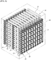
- a plurality of electrolysis cells 10 each cell being the pipe-type electrolysis cell 10 having the structure described above, is connected in series with each other to form a unit module 20 as illustrated in FIG. 1 . Therefore, it is possible to easily provide a module having desired capacity. Furthermore, a plurality of unit modules 20 may be connected in parallel with each other to increase the electrolysis capacity, as illustrated in FIG. 2 .
- the electrolysis module consisting of the pipe-type electrolysis cells 10 has a higher withstand voltage and a simpler structure than conventional cube-shaped electrolysis modules using a flat plate electrode. Furthermore, since this electrolysis module has an improved velocity profile, it is possible to minimize scale accumulation and facilitate hydrogen emissions.
- Patent Document 1 Korean Patent Application Publication No. 10-2006-0098445 (Electronic Water Treatment System And Method For Controlling The Same)
- an object of the present invention is to provide a pipe-type electrolysis cell that can reduce the manufacturing cost of an electrolysis module by reducing the number of parts thereof and simplifying a manufacturing method, and can overcome a space constraint problem by having a size that is about a half of the size of conventional electrolysis cells having the same capacity, while providing advantages of conventional technologies that are proven to be safe.
- the present invention is devised in consideration of the above problems, and is intended to provide an improved pipe-type electrolysis cell having a reduced size while maintaining an electrolysis performance, thereby saving an installation space and the manufacturing cost.
- Another object of the invention is to improve uniformity and efficiency of reaction by enabling uniform current distribution throughout pipe-type electrolysis cells arranged in multiple stages.
- the present invention provides a pipe-type electrolysis cell including: a pair of terminal electrodes including an outer electrode and an inner electrode having respective first ends electrically connected to each other and respective second ends separated from each other; and a pipe-type bipolar electrode installed between the terminal electrodes and electrically insulated from the terminal electrodes.
- the pipe-type electrolysis cell may further include: an insulation unit supporting the separated second ends of the terminal electrodes and connecting the terminal electrodes to each other; and a spiral block combined with the connected first ends of the terminal electrodes and provided with a spiral guide hole through which a fluid passes.
- the terminal electrodes may include a connection plate that supports and connects the first ends of the inner electrode and the outer electrode and which is provided with a fluid passing hole communicating with a channel formed between the inner electrode and the outer electrode, thereby guiding a fluid to the channel.
- the pipe-type electrolysis cell may further include terminal insulating spacers provided to respective ends of the bipolar electrode to electrically insulate and space the bipolar electrode from the connection plate, the inner electrode, and the outer electrode.
- Either one or both of an outside surface of the outer electrode having a pipe shape and an inside surface of the inner electrode having a pipe shape are plated with a metal having a high electrical conductivity, wherein the outside surface and the inside surface are not involved in an electrolytic reaction.
- connection plate provided with the fluid passing hole, and the outer and inner electrodes may be connected through welding.
- the fluid passing holes formed in the connection plate may be through holes formed to be aligned with spiral guide holes formed in the spiral block.
- a positioning guide pin may be formed to protrude from an outside surface of the connection plate, the spiral block may be combined with the outside surface of the connection plate, and the spiral block may be provided with a plurality of spiral guide holes that are arranged in a circumferential direction so as to correspond to the fluid passing holes of the connection plate.
- the spiral block may be provided with a positioning hole into which the positioning guide pin is inserted when the spiral block is combined with the connection plate such that the spiral guide holes are well aligned with the fluid passing holes of the connection plate.
- the insulation unit may include: an outer insulating spacer provided on an outside surface of the bipolar electrode at a middle portion in a longitudinal direction; and an inner insulating spacer provided inside the bipolar electrode at the middle portion in the longitudinal direction.
- the pipe-type electrolysis cell may further include: an insulation unit supporting and connecting the separated second ends of the terminal electrodes to each other; and a spiral block combined with the connected first ends of the terminal electrodes and provided with a spiral guide hole through which a fluid passes.
- the outer insulating spacer may include: a plurality of protrusions formed on an inside surface thereof and arranged at regular intervals in a circumferential direction thereof, at a middle portion in a longitudinal direction thereof, the protrusions being in contact with the outside surface of the middle electrode; and a pair of electrode connection portions that are provided at respective ends thereof and into which the outer electrodes are inserted, the electrode connection portions having an inner diameter larger than that of the middle portion of the outer insulating spacer such that an inside surface of the electrode connection portion and an inside surface of the middle portion of the outer insulating spacer form a step shape.
- the inner insulating spacer may include: a plurality of protrusions arranged at a middle portion of the middle electrode in a longitudinal direction, arranged at regular intervals in a circumferential direction, and formed to protrude from an outside surface of the inner insulating spacer; and a pair of electrode connection portions provided at respective ends thereof and having an outer diameter smaller than that of the middle portion of the inner insulating spacer such that an outside surface of the electrode connection portion and the outside surface of the middle portion of the inner insulating spacer form a step form, in which the electrode connection portions are inserted into the inner electrodes.
- the pipe-type electrolysis cell may further include a connection pipe or an inlet/outlet connection nipple combined with the first ends of the terminal electrodes, and used to connect one of the pipe-type electrolysis cells to another pipe-type electrolysis cell, wherein the connection pipe or the inlet/outlet connection nipple is structured such that a bottom surface thereof is sloped upwards toward an end of the connection pipe or the inlet/outlet connection nipple.
- the pipe-type electrolysis cell since the pipe-type electrolysis cell has a structure in which both the outside surface and the inside surface of the bipolar electrode are involved in electrolysis, electrolysis efficiency doubles compared with conventional electrolysis cells having the same size. Therefore, it is possible to reduce the manufacturing cost and the size of an electrolysis module manufactured by connecting a plurality of pipe-type electrolysis cells.
- one surface of an electrode which is not involved in an electrolytic reaction, is plated with a metal having a high electrical conductivity. This has an effect of uniformizing current distribution over the entire area of the electrode, resulting in improvements in uniformity and efficiency of the electrolytic reaction.
- the pipe-type electrolysis cell according to the present invention can reduce an installation space therefore in half compared with conventional electrolysis cells that require a large installation space while maintaining the same electrolysis performance, thereby reducing the cost.
- an electrolysis unit module includes a pipe-type electrolysis cell 110, a connection pipe 120 connected to an end of the pipe-type electrolysis cell 110, and an inlet/outlet connection nipple 130 combined with a second end of the pipe-type electrolysis cell 110.
- the pipe-type electrolysis cell 110 includes a pair of terminal electrodes, a bipolar electrode, an insulation unit, and a spiral block 118.
- the pair of terminal electrodes includes inner electrodes 115a and 115b, outer electrodes 114a and 114b, and connection plates 116 by which first ends of the inner electrodes 115a and 115b are electrically connected to first ends of the outer electrodes 114a and 114b.
- the bipolar electrode includes a pipe-type middle electrode 111 installed between the inner electrodes 115a and 115b and the outer electrodes 114a and 114b.
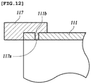
- the middle electrode 111 is a bipolar electrode having opposite polarities at opposite sides thereof. As shown in FIGS. 11 and 12 , each end of the middle electrode 111 is provided with insulating terminal spacers 117. Specifically, each end of the middle electrode 111 is provided with three insulating terminal spacers 117. The three insulating terminal spacers 117 may be arranged at an equal angular interval of 120°C. However, the number and interval of the insulating terminal spacers 117 are not limited thereto. More specifically, the insulating terminal spacers 117 may be provided to protrude outward from an end of the middle electrode 111 in a longitudinal direction and from the outside surface of the middle electrode 111.
- each insulating terminal spacer 117 is provided with a coupling pin 117a to be fitted into a coupling hole 111b provided at an end portion of the middle electrode 111. Due to the insulating terminal spacers 117, the middle electrode 111 can be spaced from the outer electrodes 114a and 114b and from the connection plates 116, by a predetermined distance. Therefore, the middle electrode 111 can be electrically insulated from the outer electrodes and the connection plates.
- the shape of the insulating terminal spacers 117 is not limited to the structure described above.
- the insulating terminal spacers 117 can have any shape if they can space the middle electrode 111 from the outer electrodes 114a and 114b and the connection plates 116, thereby electrically insulating the middle electrode 111 from the outer electrodes 114a and 114b and the connection plates 116.
- the structure of the insulating terminal spacers 117 there is a further requirement that it should not block an electrolyte solution that is introduced into a channel formed between the electrodes through fluid passing holes formed in the connection plates 116.
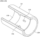
- the insulation unit includes an outer insulating spacer 112 installed outside the middle electrode 111, at a middle portion of the middle electrode 111 in a longitudinal direction thereof, and an inner insulating spacer 113 installed inside the middle portion at the middle portion. A further detailed description of the insulation will be given later.
- the outer electrodes 114a and 114b have a pipe shape.
- One outer electrode (114a) of the outer electrodes serves as a cathode and the other outer electrode (114b) serves as an anode.
- the outer insulating spacer 112 is provided between the outer electrode 114a and the outer electrode 114b to electrically insulate the outer electrodes 114a and 114b from each other and spaces the outer electrodes 114a and 114b from the middle electrode 111.
- a middle portion of the inside surface of the outer insulating spacer 112 is provided with protrusions 112a which enable the inside surface of the outer insulating spacer 112 to be spaced from the outside surface of the middle electrode 111 by a predetermined distance.
- the protrusions 112a may be arranged at regular intervals in the circumferential direction of the outer insulating spacer 112 and are in surface contact with the outside surface of the middle electrode 111. Respective ends of the outer insulating spacer 112 are provided with outer electrode connection portions 112b into which end portions of the outer electrodes 114a and 114b are inserted, in which the outer electrode connection portions 112b have an inner diameter larger than an inner diameter of the middle portion of the outer insulating spacer 112. That is, the inside surface of the electrode connection portion 112b and the inside surface of the middle portion of the insulating outer spacer 112 form a step shape. Therefore, the outer electrodes 114a and 114b are supported on and insulated from each other by the outer insulating spacer 112.
- adjacent ends (second ends) of the outer electrodes 114a and 114b are assembled with the outer insulating spacer 112, and the other ends (first ends) are respectively assembled with the connection pipes 120 or the inlet/outlet connection nipples 130.
- first ends of the outer electrodes 114a and 114b are connected to first ends of the inner electrodes 115a and 115b by the connection plates 116.
- the connection plates 116 are made of a metal.
- the first ends of the inner electrodes 115a and 115b and the first ends of the outer electrodes 114a and 114b are connected through a connection method such as welding that does not increase electrical resistance. Therefore, as to the inner electrodes 115a and 115b and the outer electrodes 114a and 114b connected by the connection plate 116, the outer electrode 114a and the inner electrode 115a, connected to each other, have the same polarity (i.e. both serving as a cathode) and the outer electrode 114b and the inner electrode 115b have the same polarity (i.e. both serving as an anode).
- the inner insulating spacer 113 is provided between the inner electrodes 115a and 115b, so that the inner electrodes 115a and 115b are electrically insulated from each other by the inner insulating spacer 113.
- the inner insulating spacer 113 also spaces and electrically insulates the inner electrodes 115a and 115b from the middle electrode 111.
- the inner insulating spacer 113 is installed at a middle portion inside the middle electrode 111 and is provided with a plurality of protrusions 113 on the outside surface thereof.
- the protrusions 113a protrude from the outside surface 113 of the inner insulating spacer 113 and are arranged at regular intervals in the circumferential direction.
- the protrusions 113 are in contact with the inside surface of the middle electrode 111.
- Respective ends of the inner insulating spacer 113 are provided with inner electrode connection portions 113b that have a smaller outer diameter than that of a middle portion of the inner insulating spacer 113 such that the outside surface of the inner electrode connection portion 113b and the outside surface of the middle portion of the inner insulating spacer 113 form a step shape. Therefore, the inner electrode connection portions 113b of the inner insulating spacer 113 can be respectively inserted into the adjacent ends of the inner electrodes 115a and 115b.
- the inner insulating spacer 113 supports the inner electrodes 115a and 115b while electrically insulating the inner electrodes 115a and 115b from each other, and also spaces and electrically insulates the inner electrodes 115a and 115b from the middle electrode 111.
- the structures of the outer insulating spacer 112 and the inner insulating spacer 113 are not limited to those described above.
- the outer insulating spacer 112 and the inner insulating spacer 113 may have any structure that can meet requirements that the outer electrodes 114a and 114b can be supported in a state of being electrically insulated from each other, the inner electrodes 115a and 115b can be supported in a state of being electrically insulated from each other, and the outer electrodes and the inner electrodes can be spaced and electrically insulated from the middle electrode 111 by a predetermined distance.
- the protrusions 112a of the outer insulating spacer 112 and the protrusions 113a of the inner insulating spacer 113 which are provided to space and electrically insulate the outer electrodes and the inner electrodes from the middle electrode 111, are preferably configured not to impede the flow of an electrolyte solution which flows along a channel provided between the outer electrode and the middle electrode and a channel provided between the inner electrode and the middle electrode.
- the bipolar electrode i.e. the pipe-type middle electrode 11 which is disposed between and spaced from the outer electrodes 114a and 114b and the inner electrodes 115a and 115b, with respect to the outer electrodes 114a and 114b and the inner electrodes 115a and 115b. Accordingly, an electrolytic reaction occurs in a state in which a fluid flows along the outside surface and the inside surface of the middle electrode 111. Since the electrolytic reaction occurs while the fluid is flowing along the outside surface and the inside surface of the middle electrode 111, the pipe-type electrolysis cell of the present invention exhibits electrolysis performance that is twice or more than that of conventional pipe-type electrolysis cells.
- the pipe-type electrolysis cell of the invention can obtain two times higher electrolysis efficiency than the conventional pipe-type electrolysis cell. Since those skilled in the art can easily understand the detailed structure and operation of the pipe-type electrolysis cell, there will be no further description thereof.
- connection plate 116 is provided with a plurality of fluid passing holes 116a that are equal in size and are arranged at regular intervals in a circumferential direction of the connection plate 116 such that the fluid can be introduced into a gap between the inner electrodes 115a and 115b and the outer electrodes 114a and 114b.
- one or more positioning guide pins 116b are formed to protrude from the outside surface of the connection plate 116. The positioning guide pins 116b are configured to enable a combined structure of the electrodes to be precisely and accurately aligned with the spiral block 118 when the combined structure of the electrodes is combined with the spiral block.
- connection plate 116 may be made of a plurality of plates arranged in multiple stages. In this case, the plates are stacked such that the fluid passing holes provided to each plate are misaligned. That is, a fluid path extending through the fluid passing holes of the plates may form a spiral shape. Alternatively, each fluid passing hole 116a may extend in a spiral form in the connection plate 116, thereby guiding the fluid along a spiral flow path.
- the spiral block 118 is connected to the outside surface of the connection plate 116.
- the spiral block 118 is provided with a plurality of spiral guide holes 118a that are arranged at intervals in a circumferential direction of the spiral block 118. Since the fluid spirally flows while passing through the spiral guide holes 118a, velocity distribution of the fluid can be uniformized.
- the spiral block 118 is provided with a positioning hole 118b that is used to position the spiral block 118 such that the guide holes 118a of the spiral block 118 can be precisely and accurately aligned with the fluid passing holes 116a of the connection plate 116 when the spiral block 118 is connected to the connection plate 116.
- connection plate 116 When the positioning guide pin 116b of the connection plate 116 is inserted into the positioning hole 118b, the fluid passing holes 116a are automatically aligned with the guides hole 118a. Therefore, the fluid can flow without flow resistance.
- the spiral block 118 is assembled with the connection pipe 120 or the inlet/outlet connection nipple 130.
- the middle electrode 111 a half of each of the outside surface and the inside surface in terms of the longitudinal direction is coated with an anode material. That is, both of the outside surface and the inside surface of the middle electrode 111 can be used for an electrolytic reaction unlike conventional arts. Therefore, electrolysis capacity is doubled.
- the outer electrode 114a serving as the cathode and the inner electrode 115a serving as the cathode are made of stainless steel or nickel alloys.
- the outer electrode 114a and the inner electrode 115a serving as the cathode are connected to the connection plate 116 through a connection method such as welding that does not increase electric resistance.
- one or more surfaces of the electrodes, which do not participate in an electrolytic reaction while the electrolyte solution flows for example, the inside surface of the inner electrode 115a or the outside surface of the outer electrode 114a, are preferably coated with a metal having a high electric conductivity, which uniformly distributes current intensity over the entire length of the electrode during the electrolytic reaction. For this reason, uniformity and efficiency of the electrolytic reaction can be improved compared with conventional multi-stage electrolytic cells, and heat generated during the electrolytic reaction can be controlled.
- the outer electrode 114b and the inner electrode 115b serving as the anode are made of titanium.
- the inside surface of the outer electrode 114a and the outside surface of the inner electrode 115b are coated with a platinum oxide to form insoluble electrodes.
- these electrodes are plated and welded in the same manner as the electrodes serving as the cathode described above, thereby maintaining the electrical conductivity.
- a plurality of pipe-type electrolysis cells 110 having the structure described above are arranged in series, and adjacent ends thereof are connected to each other by the connection pipe 120 so that a fluid can flow from one cell to another.
- the outermost electrolysis cells 110 are connected to the inlet/outlet connection nipples 130. That is, outer ends of both of the outermost pipe-type electrolysis cell 110 are connected to the connection pipes 120 or the inlet/outlet connection nipples 130. Alternatively, the outer end of one of the outermost pipe-type electrolysis cells 110 may be connected to the connection pipe 120 and the outer end of the other of the outermost pipe-type electrolysis cells 110 may be connected to the inlet/outlet connection nipple 130.
- an internal fluid channel i.e. fluid passage channel
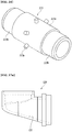
- the connection pipe 120 and/or the inlet/outlet connection nipple 130 have bottom surfaces 121 and 131 that are sloped upward toward the outer ends thereof as shown in FIGS. 17A and 17B .
- an electrolysis unit module 100 is made up of the plurality of pipe-type electrolysis cells 110 connected in series with each other.
- the pipe-type electrolysis cell 110 is structured such that the pipe-type bipolar electrode (i.e. middle electrode) is arranged between the terminal electrodes consisting of the outer electrode and the inner electrode, thereby enabling the electrolytic reaction to occur on both the inside surface and the outside surface of the bipolar electrode.
- the pipe-type electrolysis cell can obtain an electrolysis performance equal to that of a conventional pipe-type electrolysis cell even while being only half the size.
- the amount of electrode material is reduced to about 65%, and the amount of epoxy molding material and the amount of frames are also reduced by about 50%. That is, the pipe-type electrolysis cell of the invention is considerably more cost effective because it is possible to reduce the size and the material cost while maintaining electrolysis capacity.
- an electrolysis module made up of the pipe-type electrolysis cells having the structure described above is applied to a ship, it can be installed in old ships as well as new ships because it requires a reduced installation space.
- the pipe-type electrolysis cell of the present invention can be applied to an electrolysis apparatus that can electrolyze general water such as flesh water as well as an electrolysis apparatus that electrolyzes sea water, salt water, and so on.
Description
- The present invention relates to a pipe-type electrolysis cell and, more particularly, to a pipe-type electrolysis cell having a reduced size, thereby overcoming a constraint of installation space and reducing the manufacturing cost while providing advantages of a tube type electrolysis cell.
- As a typical example of an electrolytic cell for electrolyzing an electrolyte solution such as sea water, salt water, or the like, there is a pipe-type electrolysis cell.
- The pipe-type electrolysis cell has a pipe-type electrode typically consisting of an outer pipe and an inner pipe. The inner pipe is a combined bipolar tube electrode in which one portion serves as an anode and the other portion serves as a cathode. The outer pipe includes an anode portion, a cathode portion, and an insulating spacer disposed at a center portion thereof, in which the anode portion and the cathode portion are disposed to be opposite to the anode and the cathode of the inner pipe. Alternatively, both of the inner pipe and the outer pipe may be monopolar electrodes having one polarity.
- In the pipe-type electrolytic cell, when DC power is applied between the anode and the cathode to cause electrolysis while an electrolyte solution flows along the surfaces of the inner pipe and the outer pipe, electrolyzed water is produced.
- Electrolysis can be used for various process such as production of chlorine, sodium hydroxide, sodium hypochlorite, and the like through electrolysis of sea water or salt water, production of hydrogen and oxygen through electrolysis of water, production of various organic compounds through electrolysis of carbon dioxide, decomposition of ammonia or organic substances, production of acidic water and alkaline water, and the like.
- Among these processes, chemical equations of a typical electrolysis process to produce sodium hypochlorite from sea water or salt water are shown below.
Anodic reaction: 2Cl- → Cl2 + 2e-
Cathodic reaction: 2H2O + 2e- → 2OH- + H2↑
Bulk reaction: Cl2 + 2NaOH → NaOCl + NaCl + H2O
- Chlorine (Cl2) is produced at the anode side through oxidation of chlorine ions, and hydrogen gas (H2) and hydroxyl ions (OH-) are produced at the cathode side through water splitting. Hydroxyl ions (OH-) produced at the cathode side react with sodium ions (Na+) in a bulk phase to produce sodium hydroxide (NaOH), and the sodium hydroxide (NaOH) reacts with chlorine (Cl2), in a bulk phase, produced at the anode to produce sodium hypochlorite (NaOCl). Sodium hypochlorite (NaOCl) produced in this way is used to lower biological activity, or used in various applications for sterilization (disinfection) and cleaning.
- Hardness materials such as Ca and Mg contained in an electrolyte solution form scale on a cathode electrode through chemical reactions described below, during electrolysis, and the accumulated scale lowers electrolysis efficiency, resulting in an increase in cell voltage, impedes the flow of a fluid, and causes physical damage attributable to short-circuiting between electrodes in extreme cases.
Scale formation reaction: HCO3 - + NaOH → CO3 2- + H2O + Na+
Ca2+ or Mg2+ + CO3 2- → CaCO3 or MgCO3
Ca2+ or Mg2+ + 2OH- → Ca(OH)2 or Mg(OH)2
- A conventional technology of preventing accumulation of scale is disclosed in Korean Patent Application Publication No.
10-2006-0098445 - The conventional technology requires generation of uniform density of electromagnetic fields to suppress generation of scale. However, in the case in which the flow rate of fluid, flowing along the fluid passage, is not constant but fluctuates, it is difficult to maintain uniform density of electromagnetic fields. For this reason, it is difficult to effectively impede scale formation. That is, the conventional art, which prevents scale formation through an electrical method, requires an advanced technology to precisely control the intensity of current in accordance with the flow rate of fluid. Therefore, it is not easy to substantially perfectly prevent scale formation, and thus it is necessary to mechanically remove generated scale.
- To solve the problem of this technology, Korean Patent Application No.
10-2012-0032399 FIGS. 1 to 6 . - With reference to
FIGS. 1 to 6 , according to a conventional art, a pipe-type electrolysis cell 10 includes aninsulating spacer 11 disposed at a middle portion thereof, an anodeouter pipe 12 disposed on one side of theinsulating spacer 11, and a cathodeouter pipe 13 disposed on the other side of theinsulating spacer 11. A cathode inner pipe (not shown) is installed inside the anodeouter pipe 12, and an anode inner pipe 13' is installed inside the cathodeouter pipe 13. Aninsulating bushing 14, aspiral block 15, a fixing bushing 16, and an inlet/outlet connection nipple 17 are assembled with an end of theelectrolysis cell 10 by acoupling member 18. Due to the use of thespiral block 15, when a fluid flows in and out of theelectrolysis cell 10 through aspiral hole 15a formed in thespiral block 15, since a fluid passage has a spiral form, the fluid can flow at a constant uniform flow rate. This prevents hydrogen gas H2 and oxygen gas O2 generated during an electrolytic reaction from being locally concentrated in a specific portion, which removes an intervening factor of surface reaction attributable to the gases and enables uniform reaction. Therefore, it is possible to obtain effects of an improvement in efficiency of electrolytic reaction and an increase in life span of the electrolysis cell. - In addition, a plurality of
electrolysis cells 10, each cell being the pipe-type electrolysis cell 10 having the structure described above, is connected in series with each other to form aunit module 20 as illustrated inFIG. 1 . Therefore, it is possible to easily provide a module having desired capacity. Furthermore, a plurality ofunit modules 20 may be connected in parallel with each other to increase the electrolysis capacity, as illustrated inFIG. 2 . - The electrolysis module consisting of the pipe-
type electrolysis cells 10 has a higher withstand voltage and a simpler structure than conventional cube-shaped electrolysis modules using a flat plate electrode. Furthermore, since this electrolysis module has an improved velocity profile, it is possible to minimize scale accumulation and facilitate hydrogen emissions. - However, in the case of the conventional pipe-type electrolysis cell, since only one surface of the electrode is involved in an electrolytic reaction, a large amount of material is likely to be wasted. In addition, since the pipe-type electrolysis cell requires a large installation space, it is difficult to use the pipe-type electrolysis cell in small places. In addition, since the number of parts of the pipe-type electrolysis cell is large and assembling of the parts is complicated, the manufacturing cost is increased.
- In addition, in the case of the conventional pipe-type electrolysis cell, current distribution is non-uniform over the electrode. Therefore, when the conventional pipe-type electrolysis cells are arranged in multiple stages, it is difficult to obtain uniform reaction, the life span of the electrode is shortened, and excessive heat is generated.
- (Patent Document 1) Korean Patent Application Publication No.
10-2006-0098445 - Accordingly, the present invention has been made keeping in mind the above problems occurring in the related art, and an object of the present invention is to provide a pipe-type electrolysis cell that can reduce the manufacturing cost of an electrolysis module by reducing the number of parts thereof and simplifying a manufacturing method, and can overcome a space constraint problem by having a size that is about a half of the size of conventional electrolysis cells having the same capacity, while providing advantages of conventional technologies that are proven to be safe.
- That is, the present invention is devised in consideration of the above problems, and is intended to provide an improved pipe-type electrolysis cell having a reduced size while maintaining an electrolysis performance, thereby saving an installation space and the manufacturing cost.
- In addition, another object of the invention is to improve uniformity and efficiency of reaction by enabling uniform current distribution throughout pipe-type electrolysis cells arranged in multiple stages.
- In order to accomplish the above objects, the present invention provides a pipe-type electrolysis cell including: a pair of terminal electrodes including an outer electrode and an inner electrode having respective first ends electrically connected to each other and respective second ends separated from each other; and a pipe-type bipolar electrode installed between the terminal electrodes and electrically insulated from the terminal electrodes.
- The pipe-type electrolysis cell may further include: an insulation unit supporting the separated second ends of the terminal electrodes and connecting the terminal electrodes to each other; and a spiral block combined with the connected first ends of the terminal electrodes and provided with a spiral guide hole through which a fluid passes.
- The terminal electrodes may include a connection plate that supports and connects the first ends of the inner electrode and the outer electrode and which is provided with a fluid passing hole communicating with a channel formed between the inner electrode and the outer electrode, thereby guiding a fluid to the channel.
- The pipe-type electrolysis cell may further include terminal insulating spacers provided to respective ends of the bipolar electrode to electrically insulate and space the bipolar electrode from the connection plate, the inner electrode, and the outer electrode.
- Either one or both of an outside surface of the outer electrode having a pipe shape and an inside surface of the inner electrode having a pipe shape are plated with a metal having a high electrical conductivity, wherein the outside surface and the inside surface are not involved in an electrolytic reaction.
- The connection plate provided with the fluid passing hole, and the outer and inner electrodes may be connected through welding.
- The fluid passing holes formed in the connection plate may be through holes formed to be aligned with spiral guide holes formed in the spiral block.
- A positioning guide pin may be formed to protrude from an outside surface of the connection plate, the spiral block may be combined with the outside surface of the connection plate, and the spiral block may be provided with a plurality of spiral guide holes that are arranged in a circumferential direction so as to correspond to the fluid passing holes of the connection plate.
- The spiral block may be provided with a positioning hole into which the positioning guide pin is inserted when the spiral block is combined with the connection plate such that the spiral guide holes are well aligned with the fluid passing holes of the connection plate.
- The insulation unit may include: an outer insulating spacer provided on an outside surface of the bipolar electrode at a middle portion in a longitudinal direction; and an inner insulating spacer provided inside the bipolar electrode at the middle portion in the longitudinal direction.
- The pipe-type electrolysis cell may further include: an insulation unit supporting and connecting the separated second ends of the terminal electrodes to each other; and a spiral block combined with the connected first ends of the terminal electrodes and provided with a spiral guide hole through which a fluid passes.
- The outer insulating spacer may include: a plurality of protrusions formed on an inside surface thereof and arranged at regular intervals in a circumferential direction thereof, at a middle portion in a longitudinal direction thereof, the protrusions being in contact with the outside surface of the middle electrode; and a pair of electrode connection portions that are provided at respective ends thereof and into which the outer electrodes are inserted, the electrode connection portions having an inner diameter larger than that of the middle portion of the outer insulating spacer such that an inside surface of the electrode connection portion and an inside surface of the middle portion of the outer insulating spacer form a step shape.
- The inner insulating spacer may include: a plurality of protrusions arranged at a middle portion of the middle electrode in a longitudinal direction, arranged at regular intervals in a circumferential direction, and formed to protrude from an outside surface of the inner insulating spacer; and a pair of electrode connection portions provided at respective ends thereof and having an outer diameter smaller than that of the middle portion of the inner insulating spacer such that an outside surface of the electrode connection portion and the outside surface of the middle portion of the inner insulating spacer form a step form, in which the electrode connection portions are inserted into the inner electrodes.
- The pipe-type electrolysis cell may further include a connection pipe or an inlet/outlet connection nipple combined with the first ends of the terminal electrodes, and used to connect one of the pipe-type electrolysis cells to another pipe-type electrolysis cell, wherein the connection pipe or the inlet/outlet connection nipple is structured such that a bottom surface thereof is sloped upwards toward an end of the connection pipe or the inlet/outlet connection nipple.
- According to the present invention, since the pipe-type electrolysis cell has a structure in which both the outside surface and the inside surface of the bipolar electrode are involved in electrolysis, electrolysis efficiency doubles compared with conventional electrolysis cells having the same size. Therefore, it is possible to reduce the manufacturing cost and the size of an electrolysis module manufactured by connecting a plurality of pipe-type electrolysis cells.
- In addition, when constructing a multi-stage electrolysis cell, one surface of an electrode, which is not involved in an electrolytic reaction, is plated with a metal having a high electrical conductivity. This has an effect of uniformizing current distribution over the entire area of the electrode, resulting in improvements in uniformity and efficiency of the electrolytic reaction.
- The pipe-type electrolysis cell according to the present invention can reduce an installation space therefore in half compared with conventional electrolysis cells that require a large installation space while maintaining the same electrolysis performance, thereby reducing the cost.
-
-
FIG. 1 is a perspective view of a conventional unit electrolysis module; -
FIG. 2 is a perspective view of a conventional large-capacity electrolysis module; -
FIG. 3 is a perspective view of a conventional pipe-type electrolysis cell; -
FIG. 4 is an expanded view of a portion A ofFIG. 3 ; -
FIG. 5 is an expanded view of a portion B ofFIG. 3 ; -
FIG. 6 is a perspective view illustrating a spiral block shown inFIG. 5 ; -
FIG. 7 is a perspective view of a pipe-type electrolysis cell according to one embodiment of the invention; -
FIG. 8 is an expanded view of a portion D1 ofFIG. 7 ; -
FIG. 9 is an expanded view of a portion D2 ofFIG. 7 ; -
FIG. 10 is an expanded view of a portion D3 ofFIG. 7 ; -
FIG. 11 is a perspective view illustrating a middle electrode of the pipe-type electrolysis cell shown inFIG. 7 ; -
FIG. 12 is a cross-sectional view illustrating a main portion of the structure ofFIG. 11 ; -
FIG. 13 is a diagram illustrating a connection portion at which an outer electrode and an inner electrode are connected to each other; -
FIG. 14 is a diagram illustrating an outer insulating spacer ofFIG. 7 ; -
FIG. 15 is a diagram illustrating an inner insulating spacer ofFIG. 7 ; -
FIG. 16 is a diagram illustrating a spiral block ofFIG. 7 ; -
FIG. 17A is a diagram illustrating an example of a connection pipe; and -
FIG. 17B is a diagram illustrating an example of an inlet/outlet connection nipple. - Hereinbelow, a pipe-type electrolysis cell according to one embodiment of the invention will be described with reference to the accompanying drawings.
- With reference to
FIGS. 7 to 16 , according to one embodiment of the invention, an electrolysis unit module includes a pipe-type electrolysis cell 110, aconnection pipe 120 connected to an end of the pipe-type electrolysis cell 110, and an inlet/outlet connection nipple 130 combined with a second end of the pipe-type electrolysis cell 110. - The pipe-
type electrolysis cell 110 according to one embodiment invention includes a pair of terminal electrodes, a bipolar electrode, an insulation unit, and aspiral block 118. - Herein, the pair of terminal electrodes includes
inner electrodes outer electrodes connection plates 116 by which first ends of theinner electrodes outer electrodes - The bipolar electrode includes a pipe-
type middle electrode 111 installed between theinner electrodes outer electrodes - That is, the
middle electrode 111 is a bipolar electrode having opposite polarities at opposite sides thereof. As shown inFIGS. 11 and12 , each end of themiddle electrode 111 is provided with insulatingterminal spacers 117. Specifically, each end of themiddle electrode 111 is provided with three insulatingterminal spacers 117. The three insulatingterminal spacers 117 may be arranged at an equal angular interval of 120°C. However, the number and interval of the insulatingterminal spacers 117 are not limited thereto. More specifically, the insulatingterminal spacers 117 may be provided to protrude outward from an end of themiddle electrode 111 in a longitudinal direction and from the outside surface of themiddle electrode 111. To this end, each insulatingterminal spacer 117 is provided with acoupling pin 117a to be fitted into acoupling hole 111b provided at an end portion of themiddle electrode 111. Due to the insulatingterminal spacers 117, themiddle electrode 111 can be spaced from theouter electrodes connection plates 116, by a predetermined distance. Therefore, themiddle electrode 111 can be electrically insulated from the outer electrodes and the connection plates. The shape of the insulatingterminal spacers 117 is not limited to the structure described above. That is, the insulatingterminal spacers 117 can have any shape if they can space themiddle electrode 111 from theouter electrodes connection plates 116, thereby electrically insulating themiddle electrode 111 from theouter electrodes connection plates 116. However, as to the structure of the insulatingterminal spacers 117, there is a further requirement that it should not block an electrolyte solution that is introduced into a channel formed between the electrodes through fluid passing holes formed in theconnection plates 116. - The insulation unit includes an outer insulating
spacer 112 installed outside themiddle electrode 111, at a middle portion of themiddle electrode 111 in a longitudinal direction thereof, and an inner insulatingspacer 113 installed inside the middle portion at the middle portion. A further detailed description of the insulation will be given later. - The
outer electrodes spacer 112 is provided between theouter electrode 114a and theouter electrode 114b to electrically insulate theouter electrodes outer electrodes middle electrode 111. As illustrated inFIG. 15 , a middle portion of the inside surface of the outer insulatingspacer 112 is provided withprotrusions 112a which enable the inside surface of the outer insulatingspacer 112 to be spaced from the outside surface of themiddle electrode 111 by a predetermined distance. Theprotrusions 112a may be arranged at regular intervals in the circumferential direction of the outer insulatingspacer 112 and are in surface contact with the outside surface of themiddle electrode 111. Respective ends of the outer insulatingspacer 112 are provided with outerelectrode connection portions 112b into which end portions of theouter electrodes electrode connection portions 112b have an inner diameter larger than an inner diameter of the middle portion of the outer insulatingspacer 112. That is, the inside surface of theelectrode connection portion 112b and the inside surface of the middle portion of the insulatingouter spacer 112 form a step shape. Therefore, theouter electrodes spacer 112. - As described above, adjacent ends (second ends) of the
outer electrodes spacer 112, and the other ends (first ends) are respectively assembled with theconnection pipes 120 or the inlet/outlet connection nipples 130. - In addition, the first ends of the
outer electrodes inner electrodes connection plates 116. Theconnection plates 116 are made of a metal. The first ends of theinner electrodes outer electrodes inner electrodes outer electrodes connection plate 116, theouter electrode 114a and theinner electrode 115a, connected to each other, have the same polarity (i.e. both serving as a cathode) and theouter electrode 114b and theinner electrode 115b have the same polarity (i.e. both serving as an anode). - The inner
insulating spacer 113 is provided between theinner electrodes inner electrodes spacer 113. The innerinsulating spacer 113 also spaces and electrically insulates theinner electrodes middle electrode 111. - Herein, the inner insulating
spacer 113 is installed at a middle portion inside themiddle electrode 111 and is provided with a plurality ofprotrusions 113 on the outside surface thereof. Theprotrusions 113a protrude from theoutside surface 113 of the inner insulatingspacer 113 and are arranged at regular intervals in the circumferential direction. Theprotrusions 113 are in contact with the inside surface of themiddle electrode 111. Respective ends of the inner insulatingspacer 113 are provided with innerelectrode connection portions 113b that have a smaller outer diameter than that of a middle portion of the inner insulatingspacer 113 such that the outside surface of the innerelectrode connection portion 113b and the outside surface of the middle portion of the inner insulatingspacer 113 form a step shape. Therefore, the innerelectrode connection portions 113b of the inner insulatingspacer 113 can be respectively inserted into the adjacent ends of theinner electrodes insulating spacer 113 supports theinner electrodes inner electrodes inner electrodes middle electrode 111. - The structures of the outer insulating
spacer 112 and the inner insulatingspacer 113 are not limited to those described above. The outer insulatingspacer 112 and the inner insulatingspacer 113 may have any structure that can meet requirements that theouter electrodes inner electrodes middle electrode 111 by a predetermined distance. In this case, theprotrusions 112a of the outer insulatingspacer 112 and theprotrusions 113a of the inner insulatingspacer 113, which are provided to space and electrically insulate the outer electrodes and the inner electrodes from themiddle electrode 111, are preferably configured not to impede the flow of an electrolyte solution which flows along a channel provided between the outer electrode and the middle electrode and a channel provided between the inner electrode and the middle electrode. - According to the structure described above, power is oppositely supplied to the bipolar electrode, i.e. the pipe-
type middle electrode 11, which is disposed between and spaced from theouter electrodes inner electrodes outer electrodes inner electrodes middle electrode 111. Since the electrolytic reaction occurs while the fluid is flowing along the outside surface and the inside surface of themiddle electrode 111, the pipe-type electrolysis cell of the present invention exhibits electrolysis performance that is twice or more than that of conventional pipe-type electrolysis cells. That is, with the same volume as a conventional pipe-type electrolysis cell, the pipe-type electrolysis cell of the invention can obtain two times higher electrolysis efficiency than the conventional pipe-type electrolysis cell. Since those skilled in the art can easily understand the detailed structure and operation of the pipe-type electrolysis cell, there will be no further description thereof. - In addition, the
connection plate 116 is provided with a plurality of fluid passingholes 116a that are equal in size and are arranged at regular intervals in a circumferential direction of theconnection plate 116 such that the fluid can be introduced into a gap between theinner electrodes outer electrodes connection plate 116. The positioning guide pins 116b are configured to enable a combined structure of the electrodes to be precisely and accurately aligned with thespiral block 118 when the combined structure of the electrodes is combined with the spiral block. - In addition, the
connection plate 116 may be made of a plurality of plates arranged in multiple stages. In this case, the plates are stacked such that the fluid passing holes provided to each plate are misaligned. That is, a fluid path extending through the fluid passing holes of the plates may form a spiral shape. Alternatively, each fluid passinghole 116a may extend in a spiral form in theconnection plate 116, thereby guiding the fluid along a spiral flow path. - The
spiral block 118 is connected to the outside surface of theconnection plate 116. Thespiral block 118 is provided with a plurality of spiral guide holes 118a that are arranged at intervals in a circumferential direction of thespiral block 118. Since the fluid spirally flows while passing through thespiral guide holes 118a, velocity distribution of the fluid can be uniformized. In addition, thespiral block 118 is provided with apositioning hole 118b that is used to position thespiral block 118 such that the guide holes 118a of thespiral block 118 can be precisely and accurately aligned with thefluid passing holes 116a of theconnection plate 116 when thespiral block 118 is connected to theconnection plate 116. When thepositioning guide pin 116b of theconnection plate 116 is inserted into thepositioning hole 118b, thefluid passing holes 116a are automatically aligned with theguides hole 118a. Therefore, the fluid can flow without flow resistance. Thespiral block 118 is assembled with theconnection pipe 120 or the inlet/outlet connection nipple 130. - In addition, as to the
middle electrode 111, a half of each of the outside surface and the inside surface in terms of the longitudinal direction is coated with an anode material. That is, both of the outside surface and the inside surface of themiddle electrode 111 can be used for an electrolytic reaction unlike conventional arts. Therefore, electrolysis capacity is doubled. - In addition, among the terminal electrodes, the
outer electrode 114a serving as the cathode and theinner electrode 115a serving as the cathode are made of stainless steel or nickel alloys. Theouter electrode 114a and theinner electrode 115a serving as the cathode are connected to theconnection plate 116 through a connection method such as welding that does not increase electric resistance. In addition, one or more surfaces of the electrodes, which do not participate in an electrolytic reaction while the electrolyte solution flows, for example, the inside surface of theinner electrode 115a or the outside surface of theouter electrode 114a, are preferably coated with a metal having a high electric conductivity, which uniformly distributes current intensity over the entire length of the electrode during the electrolytic reaction. For this reason, uniformity and efficiency of the electrolytic reaction can be improved compared with conventional multi-stage electrolytic cells, and heat generated during the electrolytic reaction can be controlled. - In addition, among the terminal electrodes, the
outer electrode 114b and theinner electrode 115b serving as the anode are made of titanium. The inside surface of theouter electrode 114a and the outside surface of theinner electrode 115b are coated with a platinum oxide to form insoluble electrodes. Furthermore, these electrodes are plated and welded in the same manner as the electrodes serving as the cathode described above, thereby maintaining the electrical conductivity. - A plurality of pipe-
type electrolysis cells 110 having the structure described above are arranged in series, and adjacent ends thereof are connected to each other by theconnection pipe 120 so that a fluid can flow from one cell to another. - In addition, among the plurality of pipe-
type electrolysis cells 110, theoutermost electrolysis cells 110 are connected to the inlet/outlet connection nipples 130. That is, outer ends of both of the outermost pipe-type electrolysis cell 110 are connected to theconnection pipes 120 or the inlet/outlet connection nipples 130. Alternatively, the outer end of one of the outermost pipe-type electrolysis cells 110 may be connected to theconnection pipe 120 and the outer end of the other of the outermost pipe-type electrolysis cells 110 may be connected to the inlet/outlet connection nipple 130. - In at least either one of the
connection pipe 120 and the inlet/outlet connection nipple 130, an internal fluid channel, i.e. fluid passage channel, has a tapered form so that movement of fluid and separation of hydrogen are facilitated. That is, theconnection pipe 120 and/or the inlet/outlet connection nipple 130 havebottom surfaces FIGS. 17A and17B . - As described above, an electrolysis unit module 100 is made up of the plurality of pipe-
type electrolysis cells 110 connected in series with each other. - As described above, the pipe-
type electrolysis cell 110 according to the embodiment of the invention is structured such that the pipe-type bipolar electrode (i.e. middle electrode) is arranged between the terminal electrodes consisting of the outer electrode and the inner electrode, thereby enabling the electrolytic reaction to occur on both the inside surface and the outside surface of the bipolar electrode. In this way, an amount of electrolytic reactions that was performed by two conventional electrolysis modules can be performed by one electrolysis module. That is, according to the present invention, the pipe-type electrolysis cell can obtain an electrolysis performance equal to that of a conventional pipe-type electrolysis cell even while being only half the size. In addition, according to the invention, the amount of electrode material is reduced to about 65%, and the amount of epoxy molding material and the amount of frames are also reduced by about 50%. That is, the pipe-type electrolysis cell of the invention is considerably more cost effective because it is possible to reduce the size and the material cost while maintaining electrolysis capacity. - In the case in which an electrolysis module made up of the pipe-type electrolysis cells having the structure described above is applied to a ship, it can be installed in old ships as well as new ships because it requires a reduced installation space.
- The pipe-type electrolysis cell of the present invention can be applied to an electrolysis apparatus that can electrolyze general water such as flesh water as well as an electrolysis apparatus that electrolyzes sea water, salt water, and so on.
- Although the preferred embodiment of the present invention has been disclosed for illustrative purposes, those skilled in the art will appreciate that various modifications, additions and substitutions are possible. The invention is defined in the accompanying claims.
-
- 50: Electrolysis module 100: Unit electrolysis module
- 110: Pipe-type electrolysis cell 120: Connection pipe
- 130: Inlet/outlet connection nipple
Claims (15)
- A pipe-type electrolysis cell, comprising:a pair of terminal electrodes including an outer electrode and an inner electrode that are electrically connected to each other at respective first ends thereof and separated from each other at respective second ends thereof; anda pipe-type bipolar electrode installed between the terminal electrodes and electrically insulated from the terminal electrodes.
- The pipe-type electrolysis cell according to claim 1, further comprising:an insulation unit supporting the separated second ends of the terminal electrodes; anda spiral block combined with the connected first ends of the terminal electrodes and provided with a spiral guide hole through which a fluid passes.
- The pipe-type electrolysis cell according to claim 1, wherein the terminal electrodes include a connection plate that supports and connects the first ends of the inner electrode and the outer electrode, and which is provided with a fluid passing hole communicating with a channel formed between the inner electrode and the outer electrode, thereby guiding a fluid to the channel.
- The pipe-type electrolysis cell according to claim 3, further comprising terminal insulating spacers provided to respective ends of the bipolar electrode to electrically insulate and space the bipolar electrode from the connection plate, the inner electrode, and the outer electrode.
- The pipe-type electrolysis cell according to claim 1, wherein either one or both of an outside surface of the outer electrode having a pipe shape and an inside surface of the inner electrode having a pipe shape are plated with a metal having a high electrical conductivity, wherein the outside surface and the inside surface are not involved in an electrolytic reaction.
- The pipe-type electrolysis cell according to claim 3, wherein the connection plate provided with the fluid passing hole, and the outer and inner electrodes are connected through welding.
- The pipe-type electrolysis cell according to claim 3, wherein the fluid passing holes formed in the connection plate are aligned with spiral guide holes formed in the spiral block.
- The pipe-type electrolysis cell according to claim 3, wherein a positioning guide pin is formed to protrude from an outside surface of the connection plate, the spiral block is combined with the outside surface of the connection plate, and the spiral block is provided with a plurality of spiral guide holes that are arranged in a circumferential direction so as to correspond to the fluid passing holes of the connection plate.
- The pipe-type electrolysis cell according to claim 8, wherein the spiral block is provided with a positioning hole into which the positioning guide pin is inserted when the spiral block is combined with the connection plate such that the spiral guide holes are well aligned with the fluid passing holes of the connection plate.
- The pipe-type electrolysis cell according to claim 2, wherein the insulation unit comprises:an outer insulating spacer provided on an outside surface of the bipolar electrode at a middle portion in a longitudinal direction; andan inner insulating spacer provided inside the bipolar electrode at the middle portion in the longitudinal direction.
- The pipe-type electrolysis cell according to any one of claims 3 to 9, further comprising:an insulation unit supporting and connecting the separated second ends of the terminal electrodes to each other; anda spiral block combined with the connected first ends of the terminal electrodes and provided with a spiral guide hole through which a fluid passes.
- The pipe-type electrolysis cell according to claim 11, wherein the insulation unit comprises:an outer insulating spacer provided on an outside surface of the bipolar electrode at a middle portion in a longitudinal direction; andan inner insulating spacer provided inside the bipolar electrode at the middle portion in the longitudinal direction.
- The pipe-type electrolysis cell according to claim 10, wherein the outer insulating spacer comprises:a plurality of protrusions formed on an inside surface thereof and arranged at regular intervals in a circumferential direction thereof, at a middle portion in a longitudinal direction thereof, the protrusions being in contact with the outside surface of the middle electrode; anda pair of electrode connection portions that are provided at respective ends thereof and into which the outer electrodes are inserted, the electrode connection portions having an inner diameter larger than that of the middle portion of the outer insulating spacer such that an inside surface of the electrode connection portion and an inside surface of the middle portion of the outer insulating spacer form a step shape.
- The pipe-type electrolysis cell according to claim 10, wherein the inner insulating spacer comprises:a plurality of protrusions arranged at a middle portion of the middle electrode in a longitudinal direction, arranged at regular intervals in a circumferential direction, and formed to protrude from an outside surface of the inner insulating spacer; anda pair of electrode connection portions provided at respective ends thereof and having an outer diameter smaller than that of the middle portion of the inner insulating spacer such that an outside surface of the electrode connection portion and the outside surface of the middle portion of the inner insulating spacer form a step form, in which the electrode connection portions are inserted into the inner electrodes.
- The pipe-type electrolysis cell according to any one of claims 1 to 10, further comprising: a connection pipe or a inlet/outlet connection nipple combined with the first ends of the terminal electrodes, and used to connect one of the pipe-type electrolysis cells to another pipe-type electrolysis cell, wherein the connection pipe or the inlet/outlet connection nipple is structured such that a bottom surface thereof is sloped upwards toward an end of the connection pipe or the inlet/outlet connection nipple.
Applications Claiming Priority (2)
| Application Number | Priority Date | Filing Date | Title |
|---|---|---|---|
| KR1020140187430A KR101712586B1 (en) | 2014-12-23 | 2014-12-23 | An pipe type electrolysis cell |
| PCT/KR2015/011466 WO2016104935A1 (en) | 2014-12-23 | 2015-10-28 | Pipe-type electrolysis cell |
Publications (3)
| Publication Number | Publication Date |
|---|---|
| EP3239360A1 EP3239360A1 (en) | 2017-11-01 |
| EP3239360A4 EP3239360A4 (en) | 2018-11-21 |
| EP3239360B1 true EP3239360B1 (en) | 2019-11-27 |
Family
ID=56150917
Family Applications (1)
| Application Number | Title | Priority Date | Filing Date |
|---|---|---|---|
| EP15873463.2A Active EP3239360B1 (en) | 2014-12-23 | 2015-10-28 | Pipe-type electrolysis cell |
Country Status (6)
| Country | Link |
|---|---|
| US (1) | US10550485B2 (en) |
| EP (1) | EP3239360B1 (en) |
| JP (1) | JP6435413B2 (en) |
| KR (1) | KR101712586B1 (en) |
| CN (1) | CN107109671B (en) |
| WO (1) | WO2016104935A1 (en) |
Families Citing this family (2)
| Publication number | Priority date | Publication date | Assignee | Title |
|---|---|---|---|---|
| WO2018147725A1 (en) * | 2017-02-07 | 2018-08-16 | Bright Spark B.V. | Device comprising a channel, a cathode, an anode and a power source, and method for the production of chlorine dioxide |
| CN112030183B (en) * | 2020-08-26 | 2021-11-02 | 万华化学集团股份有限公司 | Sleeve type microchannel electrolytic reaction device and application thereof |
Family Cites Families (21)
| Publication number | Priority date | Publication date | Assignee | Title |
|---|---|---|---|---|
| NL174072C (en) * | 1971-09-08 | 1984-04-16 | Engelhard Corp | ELECTROLYSIS CELL. |
| JPS5268872A (en) * | 1975-12-05 | 1977-06-08 | Hitachi Cable Ltd | Electrolytic cell for generating apparatus of electrolyzed sodium hypo chlorite |
| JPS52139677A (en) * | 1976-05-18 | 1977-11-21 | Kobe Steel Ltd | Electrolytic cell of plural tubes structure |
| US4392937A (en) * | 1982-04-26 | 1983-07-12 | Uhde Gmbh | Electrolysis cell |
| AU1574588A (en) * | 1987-06-09 | 1989-01-04 | Cleanup And Recovery Corporation | System for electrolytic treatment of liquid |
| CN2064366U (en) * | 1989-12-05 | 1990-10-24 | 航空航天部航空工业规划设计研究院 | Double cathode sodium hypochlorite producer |
| US5385650A (en) * | 1991-11-12 | 1995-01-31 | Great Lakes Chemical Corporation | Recovery of bromine and preparation of hypobromous acid from bromide solution |
| RU2104961C1 (en) * | 1997-03-11 | 1998-02-20 | Харрисон Инвестментс Лтд. | Electrochemical plant |
| US20030205482A1 (en) * | 2002-05-02 | 2003-11-06 | Allen Larry D. | Method and apparatus for generating hydrogen and oxygen |
| WO2004097072A1 (en) * | 2003-04-30 | 2004-11-11 | Hydrox Holdings Limited | Method and apparatus for producing combustible fluid |
| KR100718723B1 (en) | 2005-03-03 | 2007-05-15 | 주식회사 성창엔지니어링 | electronic water treatment system and method for controlling the same |
| JP4915761B2 (en) * | 2005-03-25 | 2012-04-11 | 株式会社竹中工務店 | Flowing water electrolyzer |
| US7374645B2 (en) * | 2006-05-25 | 2008-05-20 | Clenox, L.L.C. | Electrolysis cell assembly |
| US8753490B2 (en) * | 2010-03-15 | 2014-06-17 | Unitech Co., Ltd | Electrolyzer for producing sodium hypochlorite |
| EP2631334A1 (en) * | 2012-02-24 | 2013-08-28 | Caliopa AG | Electrolysis cell, particularly for use in an assembly for creating an electrochemically activated table salt solution, and assembly with a number of such electrolysis cells |
| KR101389937B1 (en) * | 2012-03-29 | 2014-04-30 | (주) 테크윈 | A pipe type electric cell |
| KR101366343B1 (en) | 2012-07-31 | 2014-02-25 | (주) 테크윈 | Pipe type electrolyzer |
| KR101329046B1 (en) * | 2012-12-13 | 2013-11-20 | 유니테크 주식회사 | Tubular electrolytic cell for producing sodium hypochlorite |
| WO2014146043A1 (en) * | 2013-03-15 | 2014-09-18 | Kerstiens Kenny | Pressure induced gas generator system for electroloysis |
| KR101466371B1 (en) | 2013-04-30 | 2014-11-27 | 주식회사 욱영전해씨스템 | Electrolyzer for producing high concentration NaOCl |
| KR101412721B1 (en) * | 2013-05-23 | 2014-06-30 | (주) 테크윈 | An electrolysis module |
-
2014
- 2014-12-23 KR KR1020140187430A patent/KR101712586B1/en active IP Right Grant
-
2015
- 2015-10-28 WO PCT/KR2015/011466 patent/WO2016104935A1/en active Application Filing
- 2015-10-28 EP EP15873463.2A patent/EP3239360B1/en active Active
- 2015-10-28 CN CN201580069447.7A patent/CN107109671B/en active Active
- 2015-10-28 JP JP2017533467A patent/JP6435413B2/en active Active
-
2017
- 2017-06-15 US US15/623,995 patent/US10550485B2/en active Active
Non-Patent Citations (1)
| Title |
|---|
| None * |
Also Published As
| Publication number | Publication date |
|---|---|
| JP6435413B2 (en) | 2018-12-05 |
| EP3239360A1 (en) | 2017-11-01 |
| CN107109671A (en) | 2017-08-29 |
| EP3239360A4 (en) | 2018-11-21 |
| KR20160076860A (en) | 2016-07-01 |
| JP2017538868A (en) | 2017-12-28 |
| WO2016104935A1 (en) | 2016-06-30 |
| CN107109671B (en) | 2019-05-21 |
| US10550485B2 (en) | 2020-02-04 |
| US20170283962A1 (en) | 2017-10-05 |
| KR101712586B1 (en) | 2017-03-06 |
Similar Documents
| Publication | Publication Date | Title |
|---|---|---|
| KR101716349B1 (en) | Continuous electrolyzed oxidizing/reduction water generator device | |
| TWI622666B (en) | Electrolyzed water generator | |
| JPS5932548B2 (en) | Electrolysis method and electrolyzer | |
| JP5069292B2 (en) | Equipment for electrochemical water treatment | |
| US10550485B2 (en) | Pipe-type electrolysis cell | |
| CN108193223B (en) | Hypochlorite production system | |
| KR20190026597A (en) | Method and apparatus for producing highly concentrated slightly acidic electrolyzed water | |
| US10494275B2 (en) | Electrolysis module | |
| US20230295815A1 (en) | Combined Current Carrier Circulation Chamber and Frame for use in Unipolar Electrochemical Devices | |
| CN111032919B (en) | Electrolytic cell and electrode plate for electrolytic cell | |
| CN108265312A (en) | A kind of electrolytic cell of hypochlorite generator | |
| CN108193226B (en) | Composite electrode assembly | |
| JP2013076151A (en) | Electrolytic cell and electrolytic bath | |
| CN208136348U (en) | A kind of compound electrode assembly | |
| CN208136347U (en) | A kind of electrolytic cell of hypochlorite generator | |
| CN208136346U (en) | A kind of hypochlorite generator | |
| JP3727579B2 (en) | Hydrothermal electrolysis reactor and electrode | |
| US6716325B2 (en) | Electrolytic cell for hypochlorite generation | |
| JP7082002B2 (en) | Electrolytic cell and how to use it | |
| CN208136345U (en) | A kind of hypochlorite production system | |
| KR200285556Y1 (en) | Electrolyzer | |
| JP2006198562A (en) | Electrode device and electrolytic cell | |
| KR200475903Y1 (en) | tubular type electrolyzer | |
| US20220289599A1 (en) | Electrolytic reactor and methods for the electrolytic treatment of fluids | |
| JP2019042726A (en) | Method and device for producing high concentration slightly acidic electrolyzed water |
Legal Events
| Date | Code | Title | Description |
|---|---|---|---|
| STAA | Information on the status of an ep patent application or granted ep patent |
Free format text: STATUS: THE INTERNATIONAL PUBLICATION HAS BEEN MADE |
|
| PUAI | Public reference made under article 153(3) epc to a published international application that has entered the european phase |
Free format text: ORIGINAL CODE: 0009012 |
|
| STAA | Information on the status of an ep patent application or granted ep patent |
Free format text: STATUS: REQUEST FOR EXAMINATION WAS MADE |
|
| 17P | Request for examination filed |
Effective date: 20170627 |
|
| AK | Designated contracting states |
Kind code of ref document: A1 Designated state(s): AL AT BE BG CH CY CZ DE DK EE ES FI FR GB GR HR HU IE IS IT LI LT LU LV MC MK MT NL NO PL PT RO RS SE SI SK SM TR |
|
| AX | Request for extension of the european patent |
Extension state: BA ME |
|
| DAV | Request for validation of the european patent (deleted) | ||
| DAX | Request for extension of the european patent (deleted) | ||
| A4 | Supplementary search report drawn up and despatched |
Effective date: 20181019 |
|
| RIC1 | Information provided on ipc code assigned before grant |
Ipc: C25B 1/34 20060101ALI20181015BHEP Ipc: C25B 11/02 20060101ALI20181015BHEP Ipc: C25B 1/26 20060101ALI20181015BHEP Ipc: C25B 9/02 20060101ALI20181015BHEP Ipc: C25B 9/00 20060101AFI20181015BHEP |
|
| REG | Reference to a national code |
Ref country code: DE Ref legal event code: R079 Ref document number: 602015042724 Country of ref document: DE Free format text: PREVIOUS MAIN CLASS: C25B0009000000 Ipc: C25B0009060000 |
|
| GRAP | Despatch of communication of intention to grant a patent |
Free format text: ORIGINAL CODE: EPIDOSNIGR1 |
|
| STAA | Information on the status of an ep patent application or granted ep patent |
Free format text: STATUS: GRANT OF PATENT IS INTENDED |
|
| RIC1 | Information provided on ipc code assigned before grant |
Ipc: C25B 11/02 20060101ALI20190605BHEP Ipc: C25B 9/06 20060101AFI20190605BHEP Ipc: C25B 1/26 20060101ALI20190605BHEP Ipc: C25B 9/02 20060101ALI20190605BHEP Ipc: C25B 9/18 20060101ALI20190605BHEP |
|
| INTG | Intention to grant announced |
Effective date: 20190709 |
|
| GRAS | Grant fee paid |
Free format text: ORIGINAL CODE: EPIDOSNIGR3 |
|
| GRAA | (expected) grant |
Free format text: ORIGINAL CODE: 0009210 |
|
| STAA | Information on the status of an ep patent application or granted ep patent |
Free format text: STATUS: THE PATENT HAS BEEN GRANTED |
|
| AK | Designated contracting states |
Kind code of ref document: B1 Designated state(s): AL AT BE BG CH CY CZ DE DK EE ES FI FR GB GR HR HU IE IS IT LI LT LU LV MC MK MT NL NO PL PT RO RS SE SI SK SM TR |
|
| REG | Reference to a national code |
Ref country code: GB Ref legal event code: FG4D |
|
| REG | Reference to a national code |
Ref country code: CH Ref legal event code: EP |
|
| REG | Reference to a national code |
Ref country code: AT Ref legal event code: REF Ref document number: 1206743 Country of ref document: AT Kind code of ref document: T Effective date: 20191215 |
|
| REG | Reference to a national code |
Ref country code: DE Ref legal event code: R096 Ref document number: 602015042724 Country of ref document: DE |
|
| REG | Reference to a national code |
Ref country code: IE Ref legal event code: FG4D |
|
| REG | Reference to a national code |
Ref country code: NO Ref legal event code: T2 Effective date: 20191127 |
|
| REG | Reference to a national code |
Ref country code: LT Ref legal event code: MG4D |
|
| REG | Reference to a national code |
Ref country code: GR Ref legal event code: EP Ref document number: 20200400085 Country of ref document: GR Effective date: 20200318 |
|
| PG25 | Lapsed in a contracting state [announced via postgrant information from national office to epo] |
Ref country code: LT Free format text: LAPSE BECAUSE OF FAILURE TO SUBMIT A TRANSLATION OF THE DESCRIPTION OR TO PAY THE FEE WITHIN THE PRESCRIBED TIME-LIMIT Effective date: 20191127 Ref country code: SE Free format text: LAPSE BECAUSE OF FAILURE TO SUBMIT A TRANSLATION OF THE DESCRIPTION OR TO PAY THE FEE WITHIN THE PRESCRIBED TIME-LIMIT Effective date: 20191127 Ref country code: LV Free format text: LAPSE BECAUSE OF FAILURE TO SUBMIT A TRANSLATION OF THE DESCRIPTION OR TO PAY THE FEE WITHIN THE PRESCRIBED TIME-LIMIT Effective date: 20191127 Ref country code: FI Free format text: LAPSE BECAUSE OF FAILURE TO SUBMIT A TRANSLATION OF THE DESCRIPTION OR TO PAY THE FEE WITHIN THE PRESCRIBED TIME-LIMIT Effective date: 20191127 Ref country code: BG Free format text: LAPSE BECAUSE OF FAILURE TO SUBMIT A TRANSLATION OF THE DESCRIPTION OR TO PAY THE FEE WITHIN THE PRESCRIBED TIME-LIMIT Effective date: 20200227 |
|
| REG | Reference to a national code |
Ref country code: NL Ref legal event code: FP |
|
| PG25 | Lapsed in a contracting state [announced via postgrant information from national office to epo] |
Ref country code: RS Free format text: LAPSE BECAUSE OF FAILURE TO SUBMIT A TRANSLATION OF THE DESCRIPTION OR TO PAY THE FEE WITHIN THE PRESCRIBED TIME-LIMIT Effective date: 20191127 Ref country code: HR Free format text: LAPSE BECAUSE OF FAILURE TO SUBMIT A TRANSLATION OF THE DESCRIPTION OR TO PAY THE FEE WITHIN THE PRESCRIBED TIME-LIMIT Effective date: 20191127 Ref country code: IS Free format text: LAPSE BECAUSE OF FAILURE TO SUBMIT A TRANSLATION OF THE DESCRIPTION OR TO PAY THE FEE WITHIN THE PRESCRIBED TIME-LIMIT Effective date: 20200327 |
|
| PG25 | Lapsed in a contracting state [announced via postgrant information from national office to epo] |
Ref country code: AL Free format text: LAPSE BECAUSE OF FAILURE TO SUBMIT A TRANSLATION OF THE DESCRIPTION OR TO PAY THE FEE WITHIN THE PRESCRIBED TIME-LIMIT Effective date: 20191127 |
|
| PG25 | Lapsed in a contracting state [announced via postgrant information from national office to epo] |
Ref country code: DK Free format text: LAPSE BECAUSE OF FAILURE TO SUBMIT A TRANSLATION OF THE DESCRIPTION OR TO PAY THE FEE WITHIN THE PRESCRIBED TIME-LIMIT Effective date: 20191127 Ref country code: EE Free format text: LAPSE BECAUSE OF FAILURE TO SUBMIT A TRANSLATION OF THE DESCRIPTION OR TO PAY THE FEE WITHIN THE PRESCRIBED TIME-LIMIT Effective date: 20191127 Ref country code: PT Free format text: LAPSE BECAUSE OF FAILURE TO SUBMIT A TRANSLATION OF THE DESCRIPTION OR TO PAY THE FEE WITHIN THE PRESCRIBED TIME-LIMIT Effective date: 20200419 Ref country code: RO Free format text: LAPSE BECAUSE OF FAILURE TO SUBMIT A TRANSLATION OF THE DESCRIPTION OR TO PAY THE FEE WITHIN THE PRESCRIBED TIME-LIMIT Effective date: 20191127 Ref country code: CZ Free format text: LAPSE BECAUSE OF FAILURE TO SUBMIT A TRANSLATION OF THE DESCRIPTION OR TO PAY THE FEE WITHIN THE PRESCRIBED TIME-LIMIT Effective date: 20191127 |
|
| REG | Reference to a national code |
Ref country code: DE Ref legal event code: R097 Ref document number: 602015042724 Country of ref document: DE |
|
| PG25 | Lapsed in a contracting state [announced via postgrant information from national office to epo] |
Ref country code: SK Free format text: LAPSE BECAUSE OF FAILURE TO SUBMIT A TRANSLATION OF THE DESCRIPTION OR TO PAY THE FEE WITHIN THE PRESCRIBED TIME-LIMIT Effective date: 20191127 Ref country code: SM Free format text: LAPSE BECAUSE OF FAILURE TO SUBMIT A TRANSLATION OF THE DESCRIPTION OR TO PAY THE FEE WITHIN THE PRESCRIBED TIME-LIMIT Effective date: 20191127 |
|
| REG | Reference to a national code |
Ref country code: AT Ref legal event code: MK05 Ref document number: 1206743 Country of ref document: AT Kind code of ref document: T Effective date: 20191127 |
|
| PLBE | No opposition filed within time limit |
Free format text: ORIGINAL CODE: 0009261 |
|
| STAA | Information on the status of an ep patent application or granted ep patent |
Free format text: STATUS: NO OPPOSITION FILED WITHIN TIME LIMIT |
|
| PG25 | Lapsed in a contracting state [announced via postgrant information from national office to epo] |
Ref country code: ES Free format text: LAPSE BECAUSE OF FAILURE TO SUBMIT A TRANSLATION OF THE DESCRIPTION OR TO PAY THE FEE WITHIN THE PRESCRIBED TIME-LIMIT Effective date: 20191127 |
|
| 26N | No opposition filed |
Effective date: 20200828 |
|
| REG | Reference to a national code |
Ref country code: DE Ref legal event code: R079 Ref document number: 602015042724 Country of ref document: DE Free format text: PREVIOUS MAIN CLASS: C25B0009060000 Ipc: C25B0009170000 |
|
| PG25 | Lapsed in a contracting state [announced via postgrant information from national office to epo] |
Ref country code: PL Free format text: LAPSE BECAUSE OF FAILURE TO SUBMIT A TRANSLATION OF THE DESCRIPTION OR TO PAY THE FEE WITHIN THE PRESCRIBED TIME-LIMIT Effective date: 20191127 Ref country code: SI Free format text: LAPSE BECAUSE OF FAILURE TO SUBMIT A TRANSLATION OF THE DESCRIPTION OR TO PAY THE FEE WITHIN THE PRESCRIBED TIME-LIMIT Effective date: 20191127 Ref country code: AT Free format text: LAPSE BECAUSE OF FAILURE TO SUBMIT A TRANSLATION OF THE DESCRIPTION OR TO PAY THE FEE WITHIN THE PRESCRIBED TIME-LIMIT Effective date: 20191127 |
|
| REG | Reference to a national code |
Ref country code: CH Ref legal event code: PL |
|
| PG25 | Lapsed in a contracting state [announced via postgrant information from national office to epo] |
Ref country code: LU Free format text: LAPSE BECAUSE OF NON-PAYMENT OF DUE FEES Effective date: 20201028 Ref country code: MC Free format text: LAPSE BECAUSE OF FAILURE TO SUBMIT A TRANSLATION OF THE DESCRIPTION OR TO PAY THE FEE WITHIN THE PRESCRIBED TIME-LIMIT Effective date: 20191127 |
|
| REG | Reference to a national code |
Ref country code: BE Ref legal event code: MM Effective date: 20201031 |
|
| PG25 | Lapsed in a contracting state [announced via postgrant information from national office to epo] |
Ref country code: CH Free format text: LAPSE BECAUSE OF NON-PAYMENT OF DUE FEES Effective date: 20201031 Ref country code: BE Free format text: LAPSE BECAUSE OF NON-PAYMENT OF DUE FEES Effective date: 20201031 Ref country code: LI Free format text: LAPSE BECAUSE OF NON-PAYMENT OF DUE FEES Effective date: 20201031 |
|
| PG25 | Lapsed in a contracting state [announced via postgrant information from national office to epo] |
Ref country code: IE Free format text: LAPSE BECAUSE OF NON-PAYMENT OF DUE FEES Effective date: 20201028 |
|
| PG25 | Lapsed in a contracting state [announced via postgrant information from national office to epo] |
Ref country code: TR Free format text: LAPSE BECAUSE OF FAILURE TO SUBMIT A TRANSLATION OF THE DESCRIPTION OR TO PAY THE FEE WITHIN THE PRESCRIBED TIME-LIMIT Effective date: 20191127 Ref country code: MT Free format text: LAPSE BECAUSE OF FAILURE TO SUBMIT A TRANSLATION OF THE DESCRIPTION OR TO PAY THE FEE WITHIN THE PRESCRIBED TIME-LIMIT Effective date: 20191127 Ref country code: CY Free format text: LAPSE BECAUSE OF FAILURE TO SUBMIT A TRANSLATION OF THE DESCRIPTION OR TO PAY THE FEE WITHIN THE PRESCRIBED TIME-LIMIT Effective date: 20191127 |
|
| PG25 | Lapsed in a contracting state [announced via postgrant information from national office to epo] |
Ref country code: MK Free format text: LAPSE BECAUSE OF FAILURE TO SUBMIT A TRANSLATION OF THE DESCRIPTION OR TO PAY THE FEE WITHIN THE PRESCRIBED TIME-LIMIT Effective date: 20191127 |
|
| P01 | Opt-out of the competence of the unified patent court (upc) registered |
Effective date: 20230530 |
|
| PGFP | Annual fee paid to national office [announced via postgrant information from national office to epo] |
Ref country code: NL Payment date: 20231023 Year of fee payment: 9 |
|
| PGFP | Annual fee paid to national office [announced via postgrant information from national office to epo] |
Ref country code: GB Payment date: 20231025 Year of fee payment: 9 Ref country code: GR Payment date: 20231019 Year of fee payment: 9 |
|
| PGFP | Annual fee paid to national office [announced via postgrant information from national office to epo] |
Ref country code: NO Payment date: 20231023 Year of fee payment: 9 Ref country code: IT Payment date: 20231031 Year of fee payment: 9 Ref country code: FR Payment date: 20231023 Year of fee payment: 9 Ref country code: DE Payment date: 20231018 Year of fee payment: 9 |