EP3239043B1 - System und verfahren zur steuerung der flügelklappenbewegung eines flugzeugs - Google Patents
System und verfahren zur steuerung der flügelklappenbewegung eines flugzeugs Download PDFInfo
- Publication number
- EP3239043B1 EP3239043B1 EP17167104.3A EP17167104A EP3239043B1 EP 3239043 B1 EP3239043 B1 EP 3239043B1 EP 17167104 A EP17167104 A EP 17167104A EP 3239043 B1 EP3239043 B1 EP 3239043B1
- Authority
- EP
- European Patent Office
- Prior art keywords
- speed
- actuator
- actuators
- flaps
- flap
- Prior art date
- Legal status (The legal status is an assumption and is not a legal conclusion. Google has not performed a legal analysis and makes no representation as to the accuracy of the status listed.)
- Active
Links
Images

Classifications
-
- B—PERFORMING OPERATIONS; TRANSPORTING
- B64—AIRCRAFT; AVIATION; COSMONAUTICS
- B64C—AEROPLANES; HELICOPTERS
- B64C13/00—Control systems or transmitting systems for actuating flying-control surfaces, lift-increasing flaps, air brakes, or spoilers
- B64C13/02—Initiating means
-
- B—PERFORMING OPERATIONS; TRANSPORTING
- B64—AIRCRAFT; AVIATION; COSMONAUTICS
- B64C—AEROPLANES; HELICOPTERS
- B64C13/00—Control systems or transmitting systems for actuating flying-control surfaces, lift-increasing flaps, air brakes, or spoilers
-
- B—PERFORMING OPERATIONS; TRANSPORTING
- B64—AIRCRAFT; AVIATION; COSMONAUTICS
- B64C—AEROPLANES; HELICOPTERS
- B64C13/00—Control systems or transmitting systems for actuating flying-control surfaces, lift-increasing flaps, air brakes, or spoilers
- B64C13/24—Transmitting means
- B64C13/38—Transmitting means with power amplification
-
- B—PERFORMING OPERATIONS; TRANSPORTING
- B64—AIRCRAFT; AVIATION; COSMONAUTICS
- B64C—AEROPLANES; HELICOPTERS
- B64C13/00—Control systems or transmitting systems for actuating flying-control surfaces, lift-increasing flaps, air brakes, or spoilers
- B64C13/24—Transmitting means
- B64C13/38—Transmitting means with power amplification
- B64C13/50—Transmitting means with power amplification using electrical energy
-
- B—PERFORMING OPERATIONS; TRANSPORTING
- B64—AIRCRAFT; AVIATION; COSMONAUTICS
- B64C—AEROPLANES; HELICOPTERS
- B64C13/00—Control systems or transmitting systems for actuating flying-control surfaces, lift-increasing flaps, air brakes, or spoilers
- B64C13/24—Transmitting means
- B64C13/38—Transmitting means with power amplification
- B64C13/50—Transmitting means with power amplification using electrical energy
- B64C13/505—Transmitting means with power amplification using electrical energy having duplication or stand-by provisions
-
- B—PERFORMING OPERATIONS; TRANSPORTING
- B64—AIRCRAFT; AVIATION; COSMONAUTICS
- B64C—AEROPLANES; HELICOPTERS
- B64C3/00—Wings
- B64C3/38—Adjustment of complete wings or parts thereof
- B64C3/44—Varying camber
- B64C3/50—Varying camber by leading or trailing edge flaps
-
- B—PERFORMING OPERATIONS; TRANSPORTING
- B64—AIRCRAFT; AVIATION; COSMONAUTICS
- B64C—AEROPLANES; HELICOPTERS
- B64C9/00—Adjustable control surfaces or members, e.g. rudders
- B64C9/14—Adjustable control surfaces or members, e.g. rudders forming slots
-
- B—PERFORMING OPERATIONS; TRANSPORTING
- B64—AIRCRAFT; AVIATION; COSMONAUTICS
- B64C—AEROPLANES; HELICOPTERS
- B64C9/00—Adjustable control surfaces or members, e.g. rudders
- B64C9/14—Adjustable control surfaces or members, e.g. rudders forming slots
- B64C9/16—Adjustable control surfaces or members, e.g. rudders forming slots at the rear of the wing
-
- B—PERFORMING OPERATIONS; TRANSPORTING
- B64—AIRCRAFT; AVIATION; COSMONAUTICS
- B64C—AEROPLANES; HELICOPTERS
- B64C9/00—Adjustable control surfaces or members, e.g. rudders
- B64C9/14—Adjustable control surfaces or members, e.g. rudders forming slots
- B64C9/22—Adjustable control surfaces or members, e.g. rudders forming slots at the front of the wing
-
- B—PERFORMING OPERATIONS; TRANSPORTING
- B64—AIRCRAFT; AVIATION; COSMONAUTICS
- B64D—EQUIPMENT FOR FITTING IN OR TO AIRCRAFT; FLIGHT SUITS; PARACHUTES; ARRANGEMENT OR MOUNTING OF POWER PLANTS OR PROPULSION TRANSMISSIONS IN AIRCRAFT
- B64D45/00—Aircraft indicators or protectors not otherwise provided for
- B64D45/0005—Devices specially adapted to indicate the position of a movable element of the aircraft, e.g. landing gear
- B64D2045/001—Devices specially adapted to indicate the position of a movable element of the aircraft, e.g. landing gear for indicating symmetry of flaps deflection
Definitions
- Embodiments of the present disclosure generally relate to a system and method for controlling flap motion of wings of an aircraft.
- High-lift systems are utilized on wings of aircraft to increase lift or drag during take-offs and landings.
- One type of high-lift system includes flaps on trailing edges of the wings. The flaps are moveable control surfaces that may be extended during take-offs and landings, and retracted at cruising speeds.
- a variety of actuation systems may be used to extend and retract trailing-edge flaps on a wing.
- One known type of actuation system includes two drive stations, with each drive station connected to an opposite side of the flap.
- a distributed actuation system includes a drive station installed on either side of a flap with no mechanical interaction between the drive stations.
- a known drive station includes a motor, a gear train, and a drive screw that connects to the flap through an arm.
- the motor for example, an electric motor
- the drive screw converts the rotation motion of the motor and gear train into a linear motion to impart movement on the arm.
- the flap connected to the arm is extended or retracted.
- a flap is typically actuated by two drive stations, if one drive station moves at a different rate than the other drive station, the flap may skew or twist under sufficient airloads. For example, when the flap is actively extended or retracted by the two drive stations that are moving at different rates, the flap may be susceptible to skewing or twisting.
- FR2972175 describes a method for simultaneously controlling actuators for moving at least two aircraft flaps, comprising the steps of: - controlling the actuators to move the flaps to a predetermined position, - during displacement, detecting a slower actuator, - adapting the actuator control to wedge the actuators on the slowest actuator.
- WO2011/110833 describes a system for determining whether the relative rate of deployment of all the slats extending from a leading edge of an aircraft wing is the same as a predetermined relative rate of deployment.
- Each slat includes at least one slat deployment mechanism that includes a drive pinion drivingly coupled to each slat and a rotary actuator having an output shaft, the output shaft being driven by a common input drive shaft via the rotary actuator and being coupled to said drive pinion.
- the system comprises a sensor associated with each rotary actuator to generate a signal indicative of the rate of rotation of its corresponding output shaft and to supply that signal to a controller.
- the controller is configured to analyse the signals supplied by the sensors and to generate an alarm signal if a relative rate of rotation of all the output shafts differs from a predetermined relative rate of rotation.
- US2013/0009017 describes an electronically-synchronized flap system for a fixed-wing aircraft including a first wing including a first flap panel, the first flap panel being connected with a first in-board actuator and a first out-board actuator, and a second wing including a second flap panel, the second flap panel being connected with a second in-board actuator and a second out-board actuator.
- the system can further include an electronic control unit (ECU) configured to control the first and second in-board and out-board actuators to electronically synchronize the positions of the first and second flap panels.
- ECU electronice control unit
- US2013/0192453 describes a motor-driven movement system for moving a movable element, the system comprising at least two actuators, each provided with means connecting it to the movable element and each dimensioned to be capable, on its own, of driving the movable element, a central control unit being connected to the two actuators in order to be capable of sending a position setpoint (Posl, Pos2) to one or other of the actuators.
- the system further comprises control means for simultaneously controlling both actuators in terms of force in response to the position setpoint sent to one of the actuators.
- the present disclosure provides a system for controlling one or more flaps of an aircraft.
- the system includes a first flap moveably secured to a first wing of the aircraft.
- the first flap is moveable between an extended position and a retracted position.
- a first actuator is coupled to the first flap.
- a first sensor is coupled to the first actuator.
- the first sensor is configured to determine a position and speed of the first actuator.
- the first sensor is further configured to output a first sensor signal that relates to the position and the speed of the first actuator.
- a second actuator is also coupled to the first flap.
- a second sensor is coupled to the second actuator.
- the second sensor is configured to determine a position and speed of the second actuator.
- the second sensor is further configured to output a second sensor signal that relates to the position and the speed of the second actuator.
- a control unit is in communication with the first actuator, the first sensor, the second actuator, and the second sensor.
- the control unit is configured to receive the first and second sensor signals from the first and second sensors, respectively, compare the first and second sensor signals to determine a difference between the first and second sensor signals, and adjust the speed of one or both of the first or second actuators based on the difference between the first and second sensor signals.
- the control unit may be configured to adjust the speed of one or both of the first and second actuators by decreasing the speed of a leading one of the first and second actuators that leads a lagging one of the first and second actuators until the lagging one of the first and second actuators catches up to the leading one of the first and second actuators.
- the control unit may be configured to adjust the speed of one or both of the first and second actuators by increasing the speed of a lagging one of the first and second actuators that lags behind a leading one of the first and second actuators until the lagging one of the first and second actuators catches up to the leading one of the first and second actuators.
- control unit is configured to adjust the speed of one or both of the first and second actuators by decreasing the speed of a leading one of the first and second actuators that leads a lagging one of the first and second actuators and increasing the speed of the lagging one of the first and second actuators until the lagging one of the first and second actuators catches up to the leading one of the first and second actuators.
- the system may also include a second flap moveably secured to a second wing of the aircraft.
- the second flap is moveable between an extended position and a retracted position.
- a third actuator is coupled to the second flap.
- a third sensor is coupled to the third actuator.
- the third sensor is configured to determine one or both of a position or speed of the third actuator and output a third sensor signal related to one or both of the position or the speed of the third actuator.
- a fourth actuator is coupled to the second flap.
- a fourth sensor is coupled to the fourth actuator.
- the fourth sensor is configured to determine one or both of a position or speed of the fourth actuator and output a fourth sensor signal related to one or both of the position or the speed of the fourth actuator.
- the control unit is in communication with the third actuator, the third sensor, the fourth actuator, and the fourth sensor.
- the control unit is further configured to receive the third and fourth sensor signals from the third and fourth sensors, respectively, compare the third and fourth sensor signals to determine a difference between the third and fourth sensor signals, and adjust the speed of one or both of the third or fourth actuators based on the difference between the third and fourth sensor signals.
- the control unit may be configured to determine a difference between one or both of speed or position of the first and second flaps, and adjust the speed of one or both of the first and second flaps based on the difference between one or both of the speed or the position of the first and second flaps.
- the control unit may be configured determine the difference between one or both of the speed or position of the first and second flaps by analyzing the first, second, third, and fourth sensor signals.
- the control unit may be configured to adjust the speed of one or both of the first and second flaps by decreasing the speed of a leading one of the first and second flaps that leads a lagging one of the first and second flaps until the lagging one of the first and second flaps catches up to the leading one of the first and second flaps.
- the control unit is configured to adjust the speed of one or both of the first and second flaps by increasing the speed of a lagging one of the first and second flaps that lags behind a leading one of the first and second flaps until the lagging one of the first and second flaps catches up to the leading one of the first and second flaps.
- the control unit may be configured to adjust the speed of one or both of the first and second flaps by decreasing the speed of a leading one of the first and second flaps that leads a lagging one of the first and second flaps and increasing the speed of the lagging one of the first and second flaps until the lagging one of the first and second flaps catches up to the leading one of the first and second flaps.
- a method of controlling one or more flaps of an aircraft includes receiving first and second sensor signals from respective first and second sensors coupled to respective first and second actuators that are moveably secured to a first flap of a first wing of the aircraft.
- the first and second sensor signals relate to the position and the speed of the respective first and second actuators.
- the method also includes comparing the first and second sensor signals to determine a difference between the first and second sensor signals, and adjusting the speed of one or both of the first or second actuators based on the difference between the first and second sensor signals.
- the determining a difference operation may include analyzing a plurality of sensor signals output by sensors of actuators that are coupled to first and second flaps.
- the adjusting the speed operation may include decreasing the speed of a leading one of the first and second flaps that leads a lagging one of the first and second flaps until the lagging one of the first and second flaps catches up to the leading one of the first and second flaps.
- the adjusting the speed operation may include increasing the speed of a lagging one of the first and second flaps that lags behind a leading one of the first and second flaps until the lagging one of the first and second flaps catches up to the leading one of the first and second flaps.
- the adjusting the speed operation may include decreasing the speed of a leading one of the first and second flaps that leads a lagging one of the first and second flaps, and increasing the speed of the lagging one of the first and second flaps until the lagging one of the first and second flaps catches up to the leading one of the first and second flaps.
- the present disclosure provides systems and methods that reduce flap skew by sensing a position and speed of the actuators coupled to a flap, and, in response, adjust the speed of one or more of the actuators, so as to synchronize the actuators.
- the position and speed of actuators associated with one or more other flaps are sensed, and adjusted accordingly, so as to improve aerodynamic characteristics (or, stated differently, reduce negative aerodynamic effects).
- the aircraft can be a commercial aircraft, military aircraft, drone, and/or the like.
- the control unit identifies which of the actuators is a leading actuator and which of the actuators is a lagging actuator, and adjusts the speed of the leading actuator (such as by reducing its speed) so that the difference in position between the leading actuator and lagging actuator is reduced, thereby reducing the amount and/or likelihood of flap skew.
- the present disclosure provides a method of controlling first and second actuators that are used to position a flap of a wing of an aircraft, so as to identify one of the first and a second actuators as a leading actuator and one of the first and second actuators as a lagging actuator, adjusting the speed of the leading actuator, thereby allowing the lagging actuator to catch-up to the leading actuator.
- An actuator is leading if it is at a relative position and/or speed ahead of and/or greater than (in relation to a desired direction of travel) a relative position or speed of another actuator, which may be coupled to the same or a different flap. Conversely, an actuator is lagging if it is at a relative position and/or speed behind or less than (in relation to a desired direction of travel) a relative position or speed of another actuator, which may be coupled to the same or a different flap.
- a flap is leading if it is at a relative position and/or speed ahead of and/or greater than (in relation to a desired direction of travel) a relative position or speed of another flap. Conversely, a flap is lagging if it is at a relative position and/or speed behind or less than (in relation to a desired direction of travel) a relative position or speed of another flap.
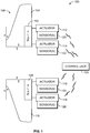
- FIG. 1 is a diagrammatic representation of a schematic view of a flap synchronization system 100, according to an embodiment of the present disclosure.
- the flap synchronization system 100 includes a flap 102 on a wing 104 of an aircraft 106 and a flap 108 on an opposite wing 110 of the aircraft 106.
- the flaps 102 and 108 may be trailing edge flaps on the wings 104 and 110, respectively.
- the flap 102 is coupled to actuators 112 and 114, while the flap 108 is coupled to actuators 116 and 118.
- the actuators 112 and 118 may be outboard actuators, while the actuators 114 and 116 may be inboard actuators.
- the actuators 112, 114, 116, and 118 may be electromechanical actuators that are configured to actuate the flaps 102 and 108 between retracted and extended positions.
- the actuators 112, 114, 116, and 118 may be drive stations, such as shown and described in United States Patent No. 9,193,479 , entitled "Monitoring of High-Lift Systems for Aircraft".
- the actuators 112, 114, 116, and 118 may be various other types of devices that are used to move the flaps 102 and 108.
- the actuators 112, 114, 116, and 118 may be or include powered pivotal harnesses, linkages, and/or the like.
- the actuators 112, 114, 116, and 118 may be secured within the wings 104 and 110.
- the actuators 112, 114, 116, and 118 may be located within a fuselage of the aircraft 106, and coupled to the flaps 102 and 108 through links, coupling, and/or the like.
- the actuators 112 and 114 may be installed on opposite sides or ends of the flap 102, while the actuators 116 and 118 may be installed on opposite sides or ends of the flap 108.
- the actuators 112 and 114 may be installed at other areas of the flap, while the actuators 116 and 118 may be installed at different areas of the flaps 108.
- the aircraft 106 may provide a distributed high-lift system.
- each of the flaps 102 and 108 may be coupled to additional actuators.
- each of the flaps 102 may be coupled to three or more actuators.
- One or more sensors 120 are coupled to the actuator 112, and optionally also to the flap 102.
- the sensor(s) 120 is (are) configured to sense a rate or speed of the actuator 112, and optionally also of the flap 102.
- the sensor(s) 120 is (are) also configured to sense a position of the actuator 112, and optionally also of the flap 102.
- the sensor(s) 120 may be secured within the wing 104.
- the sensor(s) 120 may be located within a fuselage of the aircraft 106, and coupled to the actuator 112 and optionally also to the flap 102, through links, coupling, and/or the like.
- One or more sensors 122 are coupled to the actuator 114 and optionally also to the flap 102.
- the sensor(s) 122 is (are) configured to sense a rate or speed of the actuator 114 and optionally also of the flap 102.
- the sensor(s) 122 is (are) also configured to sense a position of the actuator 114 and optionally also of the flap 102.
- the sensor(s) 122 may be secured within the wing 104.
- the sensor(s) 122 may be located within a fuselage of the aircraft 106, and coupled to the actuator 114 and optionally also to the flap 102, through links, coupling, and/or the like.
- One or more sensors 124 are coupled to the actuator 116 and optionally also to the flap 108.
- the sensor(s) 124 is (are) configured to sense a rate or speed of the actuator 116 and optionally also of the flap 108.
- the sensor(s) 124 is (are) also configured to sense a position of the actuator 116 and optionally also of the flap 108.
- the sensor(s) 124 may be secured within the wing 110.
- the sensor(s) 124 may be located within a fuselage of the aircraft 106, and coupled to the actuator 116 and optionally also to the flap 108, through links, coupling, and/or the like.
- One or more sensors 126 are coupled to the actuator 118 and optionally also to the flap 108.
- the sensor(s) 126 is (are) configured to sense a rate or speed of the actuator 118 and optionally also of the flap 108.
- the sensor(s) 126 is (are) also configured to sense a position of the actuator 118 and optionally also of the flap 108.
- the sensor(s) 126 may be secured within the wing 110.
- the sensor(s) 126 may be located within a fuselage of the aircraft 106, and coupled to the actuator 118 and optionally also to the flap 108, through links, coupling, and/or the like.
- a control unit 130 is operatively coupled to and in communication with the actuators 112, 114, 116, and 118.
- the control unit 130 may be located within a fuselage of the aircraft 106 (such as within a cockpit), and may be coupled to each actuator 112, 114, 116, and 118 through one or more wired or wireless connections.
- the control unit 130 is configured to control operation of the actuators 112, 114, and 116, and 118 to control movement of the flaps 102 and 108 based on input from an operator, such as a pilot of the aircraft 106.
- the control unit 130 is also coupled to and in communication with the sensors 120, 122, 124 and 126, such as through one or more wired or wireless connections.
- the control unit 130 receives signals from the sensors 120, 122, 124, and 126 to determine the speed and position of each actuator 112, 114, 116, and 118. Based on the signals received from the sensors 120, 122, 124, and 126, the control unit 130 may adjust the motion of the actuators 112, 114, 116, and 118. For example, the control unit 130 may adjust the speed of the actuators 112 and 114 based on the signals received from the sensors 120 and 122 to ensure that the actuators 112 and 114 are synchronized and moving the flap 102 at the same rate.
- control unit 130 may adjust the speed of the actuators 116 and 118 based on the signals received from the sensors 124 and 126 to ensure that the actuators 116 and 118 are synchronized and moving the flap 108 at the same rate. Additionally, the control unit 130 may also sense the speed and position of each flap 102 and 108 based on the signals received from the sensors 120, 122, 124, and 126 and adjust the motion of the flaps 102 and 108 to ensure that both the flaps 102 and 108 are synchronized, at a desired position, and moving at a desired rate.
- the control unit 130 receives signals from the sensors 120 and 122.
- the received signals relate to the speed of the actuators 112, 114, and to the position of the actuators 112, 114, optionally also to the speed of the flap 102, and/or the position of the flap 102.
- the signals output by the sensors 120 and 122 and received by the control unit 130 provide position and speed data of the actuators 112 and 114, respectively.
- the control unit 130 compares the signals received from the sensors 120 and 122. The control unit 130 determines whether there is a positional and speed difference between the actuators 112 and 114 based on the signals received from the sensors 120 and 122. If there is no difference, the control unit 130 continues to operate the actuators 112 and 114 without adjustment. If, however, there is a positional and speed difference between the actuators 112 and 114, the control unit 130 adjusts the motion of the actuators 112 and 114.
- control unit 130 may reduce the speed of the actuator 112 until the actuator 114 catches up to the position of the actuator 112, at which point the control unit 130 operates the actuators 112 and 114 at the same speed or rate.
- control unit 130 may reduce the speed of the actuator 112 until the actuator 114 catches up to the position and speed of the actuator 112, at which point the control unit 130 operates the actuators 112 and 114 at the same speed.
- control unit 130 monitors the motion of the actuators 112 and 114 to determine if one of the actuators 112 and 114 is lagging behind the other of the actuators 112 and 114. The control unit 130 then adjusts the speed of the leading actuator 112 or 114 so that the lagging actuator 112 or 114 catches up, thereby synchronizing the actuators 112 and 114 and reducing a likelihood of the flap 102 skewing or twisting (or otherwise controlling a magnitude of skewing or twisting within acceptable limits).
- control unit 130 compares the signals received from the sensors 124 and 126. The control unit 130 determines whether there is a positional and speed difference between the actuators 116 and 118 based on the signals received from the sensors 124 and 126. If there is no difference, the control unit 130 continues to operate the actuators 116 and 118 without adjustment. If, however, there is a positional and speed difference between the actuators 116 and 118, the control unit 130 adjusts the motion of the actuators 116 and 118.
- the control unit 130 may reduce the speed of the actuator 116 until the actuator 118 catches up to the position of the actuator 118, at which point the control unit 130 operates the actuators 116 and 118 at the same speed.
- the control unit 130 may reduce the speed of the actuator 116 until the actuator 118 catches up to the position and speed of the actuator 116, at which point the control unit 130 operates the actuators 116 and 118 at the same speed.
- control unit 130 monitors the motion of the actuators 116 and 118 to determine if one of the actuators 116 and 118 is lagging behind the other of the actuators 116 and 118. The control unit 130 then adjusts the speed of the leading actuator 116 or 118 so that the lagging actuator 116 or 118 catches up, thereby synchronizing the actuators 116 and 118 and reducing a likelihood of the flap 108 skewing or twisting (or otherwise controlling a magnitude of skewing or twisting within acceptable limits).
- control unit 130 monitors motion of the flaps 102 and 108 in relation to one another in order to ensure synchronized motion therebetween. As described above, the control unit 130 synchronizes motion of the actuators 112 and 114 coupled to the flap 102, as well as the motion of the actuators 116 and 118 coupled to the flap 108 in order to reduce the likelihood of the flaps skewing or twisting (or otherwise controlling a magnitude of skewing or twisting within acceptable limits).
- the control unit 130 determines the position and speed of each flap 102 and 108. The control unit 130 determines whether there is a difference between the position and/or speed of the flaps 102 and 108.
- the control unit 130 refrains from adjusting the motion of the flaps 102 and 108. If, however, the control unit 130 determines that one of the flaps 102 and 108 is lagging behind the other of the flaps 102 or 108 (with respect to position and/or speed), the control unit 130 adjusts the speed of the leading flap 102 or 108 until the lagging flap 102 or 108 catches up to the leading flap 102 or 108. When the lagging flap 102 or 108 catches up to the leading flap 102 or 108, the control unit 130 operates the flaps 102 and 108 (through the respective actuators 112, 114, 116, and 118) at the same rate.
- control unit 130 is in communication with actuators 112, 114, 116, 118, and the sensors 120, 122, 124, and 126.
- the control unit receives sensor signals from the sensors 120 and 112, for example.
- the sensor signals relate to one or both of a position or speed of a respective actuator 112 and 114.
- the control unit 130 compares the received second sensor signals to determine a difference therebetween.
- the control unit 130 adjusts the speed of one or both of the actuators 112 and 114 based on the difference between the first and second sensor signals. For example, the control unit 130 may slow the speed of a leading actuator until a lagging actuator catches up to the leading actuator.
- control unit 130 may optionally increase the speed of a lagging actuator until the lagging actuator catches up to the leading actuator. In at least one other embodiment, the control unit 130 may increase the speed of a lagging actuator and decrease the speed of a leading actuator until the lagging actuator catches up to the leading actuator. The control unit 130 may operate the actuators 116 and 118 in a similar fashion.
- control unit 130 may compare the position and speed of the flaps 102 and 108.
- the control unit 130 may decrease the speed of a leading flap until the lagging flap catches up to a leading flap.
- control unit 130 may increase the speed of a lagging flap until the lagging flap catches up to the leading flap.
- control unit 130 may increase the speed of a lagging flap and decrease the speed of a leading flap until the lagging flap catches up to the leading flap.
- control unit may include any processor-based or microprocessor-based system including systems using microcontrollers, reduced instruction set computers (RISC), application specific integrated circuits (ASICs), logic circuits, and any other circuit or processor including hardware, software, or a combination thereof capable of executing the functions described herein.
- RISC reduced instruction set computers
- ASICs application specific integrated circuits
- the control unit 130 may be or include one or more processors that are configured to control operation of the flaps 102 and 108, as described above.
- the control unit 130 is configured to execute a set of instructions that are stored in one or more storage elements (such as one or more memories), in order to process data.
- the control unit 130 may include or be coupled to one or more memories.
- the storage elements may also store data or other information as desired or needed.
- the storage elements may be in the form of an information source or a physical memory element within a processing machine.
- the set of instructions may include various commands that instruct the control unit 130 as a processing machine to perform specific operations such as the methods and processes of the various embodiments of the subject matter described herein.
- the set of instructions may be in the form of a software program.
- the software may be in various forms such as system software or application software. Further, the software may be in the form of a collection of separate programs, a program subset within a larger program or a portion of a program.
- the software may also include modular programming in the form of object-oriented programming.
- the processing of input data by the processing machine may be in response to user commands, or in response to results of previous processing, or in response to a request made by another processing machine.
- the diagrams of embodiments herein may illustrate one or more control or processing units, such as the control unit 130.
- the processing or control units may represent circuits, circuitry, or portions thereof that may be implemented as hardware with associated instructions (e.g., software stored on a tangible and non-transitory computer readable storage medium, such as a computer hard drive, ROM, RAM, or the like) that perform the operations described herein.
- the hardware may include state machine circuitry hardwired to perform the functions described herein.
- the hardware may include electronic circuits that include and/or are connected to one or more logic-based devices, such as microprocessors, processors, controllers, or the like.
- control unit 130 may represent processing circuitry such as one or more of a field programmable gate array (FPGA), application specific integrated circuit (ASIC), microprocessor(s), and/or the like.
- FPGA field programmable gate array
- ASIC application specific integrated circuit
- microprocessor(s) and/or the like.
- the circuits in various embodiments may be configured to execute one or more algorithms to perform functions described herein.
- the one or more algorithms may include aspects of embodiments disclosed herein, whether or not expressly identified in a flowchart or a method.
- the terms "software” and “firmware” are interchangeable, and include any computer program stored in memory for execution by a computer, including RAM memory, ROM memory, EPROM memory, EEPROM memory, and non-volatile RAM (NVRAM) memory.
- RAM memory random access memory
- ROM memory read-only memory
- EPROM memory erasable programmable read-only memory
- EEPROM memory electrically erasable programmable read-only memory
- NVRAM non-volatile RAM
- Figure 2 illustrates a flow chart of a method of synchronizing actuators coupled to a flap of wing of an aircraft, according to an embodiment of the present disclosure.
- the control unit 130 (shown in Figure 1 ) may operate according to the flow chart shown and described with respect to Figure 2 .
- a command is input from a pilot flap handle, or other such input device.
- sensed signals such as output by one or more sensors coupled to actuators and/or a flap
- first and second actuators coupled to a flap of a wing
- the control unit 130 receives sensed signals from the control unit 130.
- it is determined (such as by the control unit 130) if there is a positional difference between the sensed signals. If there is a positional difference, the speed of a leading actuator is reduced until a lagging actuator catches up to the leading actuator at 204. Optionally, the speed of the lagging actuator may be increased until the lagging actuator catches up to the leading actuator.
- the speed of the leading actuator may be reduced, and the speed of the lagging actuator may be increased until the lagging actuator catches up to the leading actuator.
- the method then proceed from 204 to 206, in which it is determined if there is a speed difference between the sensed signals. If there is a speed difference between the sensed signals, the method proceeds from 206 to 208, in which the speed of the leading actuator is reduced until the lagging actuator catches up to the leading actuator.
- the speed of the lagging actuator may be increased until the lagging actuator catches up to the leading actuator.
- the speed of the leading actuator may be reduced, and the speed of the lagging actuator may be increased until the lagging actuator catches up to the leading actuator. The method then returns to 200.
- the method proceeds from 202 to 206. If, at 206, there is not a speed difference between the sensed signals, the method returns to 200.
- Figure 3 illustrates a flow chart of a method of synchronizing flaps moveably secured to wings of an aircraft, according to an embodiment of the present disclosure.
- the control unit 130 (shown in Figure 1 ) may operate according to the flow chart shown and described with respect to Figure 3 .
- a command is input from a pilot flap handle, or other such input device.
- sensed signals related to position and speed of flaps on opposite wings of an aircraft are received, such as by the control unit 130.
- the control unit 130 may compare the flaps to one another, after the control unit 130 has synchronized the actuators coupled to each flap to reduce the likelihood of flap skew or twist (or otherwise controlling a magnitude of skewing or twisting within acceptable limits).
- the method shown and described in Figure 3 may occur subsequent to, or simultaneously with, the method shown and descried in Figure 2 .
- the sensed signals may be output by the sensors coupled to the actuators and/or flaps.
- the flaps it is determined (such as by the control unit 130) if there is a positional difference between the flaps.
- the positions of the flaps may be compared relative to one another (through an analysis of the sensed signals) to determine if there is a difference between angular, linear, and/or rotational positions of the flaps. If there is a positional difference between the flaps, the method proceeds from 302 to 304, in which the speed of a leading flap is reduced until a lagging flap catches up to the leading flap. Optionally, the speed of the lagging flap may be increased until the lagging flap catches up to the leading flap.
- the speed of the leading flap may be reduced, and the speed of the lagging flap may be increased until the lagging flap catches up to the leading flap.
- the method then proceeds from 304 to 306, in which it is determined if there is a speed difference between the flaps. If there is a speed difference between the flaps, the method proceeds from 306 to 308, in which the speed of the leading flap is reduced until the lagging flap catches up to the leading flap.
- the speed of the lagging flap may be increased until the lagging flap catches up to the leading flap.
- the speed of the leading flap may be reduced, and the speed of the lagging flap may be increased until the lagging flap catches up to the leading flap. The method then returns to 300.
- the method proceeds from 302 to 306. If, at 306, there is not a speed difference between the flaps, the method returns to 300.
- control unit 130 may compare and adjust positions and speeds of actuators and/or flaps. The comparison and adjustment may occur after high lift systems have been monitored for errors, such as described in United States Patent No. 9,193,479 , entitled “Monitoring of High-Lift Systems for Aircraft.”
- the control unit 130 and/or another controller or control unit may monitor the high lift systems for errors.
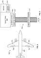
- FIG 4 is a diagrammatic representation of a top plan view of the aircraft 106, according to an embodiment of the present disclosure.
- the aircraft 106 includes a fuselage 107 and the wings 104 and 110 extending from respective right and left sides of the fuselage 107.
- the wings 104 and 110 include the extendable flaps 102 and 108 that are configured to increase drag or lift when extended from a trailing edge of the wings 104 and 110.
- the flaps 102 and 108 are part of a high-lift system implemented in the aircraft 106. Although one flap is illustrated on each wing 104 and 110, it is to be understood that multiple flaps may be installed on each of the wings 104 and 110.
- the control unit 130 extends or retracts the flaps 102 and 108 in response to inputs from a pilot, a flight control system, and/or the like.
- the control unit 130 may provide electrical power to each of the actuators 112, 114, 116, and 118 (electrical power may also or alternatively be supplied by the aircraft electrical power system).
- the actuators 112, 114, 116, and 118 may be electrically controlled, and may therefore be referred to as Electrical-Mechanical Actuators (EMAs).
- EMAs Electrical-Mechanical Actuators
- the control unit 130 monitors operation of the actuators 112, 114, 116, and 118 through the sensors 120, 122, 124, and 126, which may be integrated with the actuators 112, 114, 116, and 118, respectively.
- Figure 5 is a diagrammatic representation of an actuator 500, according to an embodiment of the present disclosure.
- One or more of the actuators 112, 114, 116, and 118 may be configured as the actuator 500, which may be a drive station.
- the actuator 500 may include an electric motor 501, a gear train 502, and a drive screw 503.
- the motor 501 is able to turn clockwise or counterclockwise in response to the signals from the control unit 130 (shown in Figure 1 ).
- the rotational motion of the motor 501 turns a series of gears within the gear train 502, which may be used to slow down the rotational motion of the motor 501.
- the gear train 502 in turn imparts rotational motion on the drive screw 503.
- the drive screw 503 includes a connection member 510, such as a ball nut and gimbal, that moves upward or downward along the drive screw 503 as the drive screw 503 turns.
- the drive screw 503 converts the rotational motion of the motor 501 and the gear train 502 into a linear motion of the connection member 510.
- the connection member 510 is configured to attach to one end of an arm (not shown), while the other end of the arm connects to a side of a flap.
- the connection member 510 moves up and down on the drive screw 503, the motion imparts movement on the arm to extend or retract the flap.
- the actuator 500 may also include a no-back device 520.
- the no-back device 520 acts as a brake to ensure irreversibility of the flap if the actuator 500 becomes disconnected from the flap. For example, if the motor 501 is inoperable, then the no-back device 520 engages to stop the flap from moving.
- the actuator 500 may also include an integrated position sensor 522.
- the position sensor 522 may be positioned between the no-back device 520 and the flap, and monitors an output position of the actuator 500 (for example, the rotation angle of the drive screw 503).
- the position sensor 522 may alternatively be installed at the connection member 510, and/or directly attached to the flap.
- the actuator 500 may also include a motor sensor 524.
- the motor sensor 524 may be configured to monitor a current draw or load on the motor 501.
- the motor sensor 524 may also monitor a position and/or speed of the motor 501.
- the position of the motor 501 may be indicated by a number of turns in either a forward or a reverse direction with a hall effect or a rotary type sensor, for example.
- Embodiments of the present disclosure provide systems and methods that synchronize flap motion of one or more wings of an aircraft. Embodiments of the present disclosure provide systems and methods that prevent, minimize, or other reduce the potential of a flap to skew or twist during operation. Embodiments of the present disclosure provide systems and methods that prevent, minimize, or otherwise reduce asymmetry between wings of an aircraft flap system. Embodiments of the present disclosure may be used to control leading edge flaps and/or trailing edge flaps.
- a structure, limitation, or element that is "configured to” perform a task or operation is particularly structurally formed, constructed, or adapted in a manner corresponding to the task or operation.
- an object that is merely capable of being modified to perform the task or operation is not “configured to” perform the task or operation as used herein.
Landscapes
- Engineering & Computer Science (AREA)
- Aviation & Aerospace Engineering (AREA)
- Automation & Control Theory (AREA)
- Mechanical Engineering (AREA)
- Radar Systems Or Details Thereof (AREA)
- Transmission Devices (AREA)
Claims (15)
- System zur Steuerung einer oder mehrerer Klappen eines Flugzeugs (106), wobei das System Folgendes aufweist:eine erste Klappe (102), welche bewegbar an einem ersten Flügel (104) des Flugzeugs (106) befestigbar ist, wobei die erste Klappe (102) zwischen einer ausgefahrenen Position und einer eingefahrenen Position bewegbar ist;einen ersten Aktuator (112), welcher mit der ersten Klappe (102) gekoppelt ist;einen ersten Sensor (120), welcher mit dem ersten Aktuator (112) gekoppelt ist, wobei der erste Sensor (120) konfiguriert ist, um eine Position und Geschwindigkeit des ersten Aktuators (112) zu bestimmen und um ein erstes Sensorsignal, welches die Position und die Geschwindigkeit des ersten Aktuators (112) betrifft, auszugeben;einen zweiten Aktuator (114), welcher mit der ersten Klappe (102) gekoppelt ist;einen zweiten Sensor (122), welcher mit dem zweiten Aktuator (114) gekoppelt ist, wobei der zweite Sensor (122) konfiguriert ist, um eine Position und Geschwindigkeit des zweiten Aktuators (114) zu bestimmen und um ein zweites Sensorsignal, welches die Position und die Geschwindigkeit des zweiten Aktuators (114) betrifft, auszugeben; undeine Steuereinheit (130), welche mit dem ersten Aktuator (112), dem ersten Sensor (120), dem zweiten Aktuator (114) und dem zweiten Sensor (122) in Kommunikationsverbindung ist, wobei die Steuereinheit (130) zu Folgendem konfiguriert ist:Empfangen des ersten und zweiten Sensorsignals von dem ersten bzw. zweiten Sensor (120, 122);Vergleichen des ersten und zweiten Sensorsignals zum Bestimmen einer Differenz zwischen dem ersten und zweiten Sensorsignal; undEinstellen der Geschwindigkeit von einem oder beiden des ersten oder zweiten Aktuators (112, 114) basierend auf der Differenz zwischen dem ersten und zweiten Sensorsignal.
- System nach Anspruch 1, wobei die Steuereinheit (130) konfiguriert ist, um die Geschwindigkeit von einem oder beiden des ersten und zweiten Aktuators (112, 114) durch das Verringern der Geschwindigkeit eines vorausgehenden des ersten und zweiten Aktuators (112, 114), welcher einem zurückbleibenden des ersten und zweiten Aktuators (112, 114) vorausgeht, einzustellen, bis der zurückbleibende des ersten und zweiten Aktuators (112, 114) den vorausgehenden des ersten und zweiten Aktuators (112, 114) einholt.
- System nach Anspruch 1, wobei die Steuereinheit (130) konfiguriert ist, um die Geschwindigkeit von einem oder beiden des ersten und zweiten Aktuators (112, 114) durch das Erhöhen der Geschwindigkeit eines zurückbleibenden des ersten und zweiten Aktuators (112, 114), welcher hinter einem vorausgehenden des ersten und zweiten Aktuators (112, 114) zurückbleibt, einzustellen, bis der zurückbleibende des ersten und zweiten Aktuators (112, 114) den vorausgehenden des ersten und zweiten Aktuators (112, 114) einholt.
- System nach Anspruch 1, wobei die Steuereinheit (130) konfiguriert ist, um die Geschwindigkeit von einem oder beiden des ersten und zweiten Aktuators (112, 114) durch das Verringern der Geschwindigkeit eines vorausgehenden des ersten und zweiten Aktuators (112, 114), welcher einem zurückbleibenden des ersten und zweiten Aktuators (112, 114) vorausgeht, und durch das Erhöhen der Geschwindigkeit des zurückbleibenden des ersten und zweiten Aktuators (112, 114) einzustellen, bis der zurückbleibende des ersten und zweiten Aktuators (112, 114) den vorausgehenden des ersten und zweiten Aktuators (112, 114) einholt.
- System nach Anspruch 1, welches ferner Folgendes aufweist:eine zweite Klappe (108), welche bewegbar an einem zweiten Flügel (110) des Flugzeugs (106) befestigbar ist, wobei die zweite Klappe (108) zwischen einer ausgefahrenen Position und einer eingefahrenen Position bewegbar ist;einen dritten Aktuator (116), welcher mit der zweiten Klappe (108) gekoppelt ist;einen dritten Sensor (124), welcher mit dem dritten Aktuator (116) gekoppelt ist, wobei der dritte Sensor (124) konfiguriert ist, um eine Messung des dritten Aktuators (116) zu bestimmen und um ein drittes Sensorsignal, welches die Messung des dritten Aktuators (116) betrifft, auszugeben;einen vierten Aktuator (118), welcher mit der zweiten Klappe (108) gekoppelt ist, einen vierten Sensor (126) welcher mit dem vierten Aktuator (118) gekoppelt ist, wobei der vierte Sensor (126) konfiguriert ist, um eine Messung des vierten Aktuators (118) zu bestimmen und um ein viertes Sensorsignal, welches die Messung des vierten Aktuators (118) betrifft, auszugeben,wobei sowohl die Messung des dritten Aktuators als auch die Messung des vierten Aktuators eines von den Folgenden aufweisen: eine Position des entsprechenden Aktuators, eine Geschwindigkeit des entsprechenden Aktuators und eine Position und Geschwindigkeit des entsprechenden Aktuators;wobei die Steuereinheit (130) mit dem dritten Aktuator (116), dem dritten Sensor (124), dem vierten Aktuator (118) und dem vierten Sensor (126) in Kommunikationsverbindung ist, wobei die Steuereinheit (130) ferner zu Folgendem konfiguriert ist:Empfangen des dritten und vierten Sensorsignals von dem dritten bzw. vierten Sensor (124, 126);Vergleichen des dritten und vierten Sensorsignals zum Bestimmen einer Differenz zwischen dem dritten und vierten Sensorsignal; undEinstellen der Geschwindigkeit von einem oder beiden des dritten oder vierten Aktuators (116, 118) basierend auf der Differenz zwischen dem dritten und vierten Sensorsignal.
- System nach Anspruch 5, wobei die Steuereinheit (130) zu Folgendem konfiguriert ist:Bestimmen einer Differenz zwischen einer oder beiden von der Geschwindigkeit oder Position der ersten und zweiten Klappe (102, 108); undEinstellen der Geschwindigkeit von einer oder beiden der ersten und zweiten Klappe (102, 108) basierend auf der Differenz zwischen einer oder beiden von der Geschwindigkeit oder Position der ersten und zweiten Klappe (102, 108).
- System nach Anspruch 6, wobei die Steuereinheit (130) zum Bestimmen der Differenz zwischen einer oder beiden von der Geschwindigkeit oder Position der ersten und zweiten Klappe (102, 108) durch Analysieren des ersten, zweiten, dritten und vierten Sensorsignals konfiguriert ist.
- System nach Anspruch 6, wobei die Steuereinheit (130) konfiguriert ist, um die Geschwindigkeit von einer oder beiden der ersten und zweiten Klappe (102, 108) durch das Verringern der Geschwindigkeit einer vorausgehenden der ersten und zweiten Klappe (102, 108), welche einer zurückbleibenden der ersten und zweiten Klappe (102, 108) vorausgeht, einzustellen, bis die zurückbleibende der ersten und zweiten Klappe (102, 108) die vorausgehende der ersten und zweiten Klappe (102, 108) einholt.
- System nach Anspruch 6, wobei die Steuereinheit (130) konfiguriert ist, um die Geschwindigkeit von einer oder beiden der ersten und zweiten Klappe (102, 108) durch das Erhöhen der Geschwindigkeit einer zurückbleibenden der ersten und zweiten Klappe (102, 108), welche hinter einer vorausgehenden der ersten und zweiten Klappe (102, 108) zurückbleibt, einzustellen, bis die zurückbleibende der ersten und zweiten Klappe (102, 108) die vorausgehende der ersten und zweiten Klappe (102, 108) einholt.
- System nach Anspruch 6, wobei die Steuereinheit (130) konfiguriert ist, um die Geschwindigkeit von einer oder beiden der ersten und zweiten Klappe (102, 108) durch das Verringern der Geschwindigkeit einer vorausgehenden der ersten und zweiten Klappe (102, 108), welche einer zurückbleibenden der ersten und zweiten Klappe (102, 108) vorausgeht, und durch das Erhöhen der Geschwindigkeit der zurückbleibenden der ersten und zweiten Klappe (102, 108) einzustellen, bis die zurückbleibende der ersten und zweiten Klappe (102, 108) die vorausgehende der ersten und zweiten Klappe (102, 108) einholt.
- Verfahren zur Steuerung einer oder mehrerer Klappen eines Flugzeugs, wobei das Verfahren Folgendes aufweist:Empfangen eines ersten und eines zweiten Sensorsignals von dem entsprechenden ersten und zweiten Sensor (120, 122), welcher mit dem entsprechenden ersten und zweiten Aktuator (112, 114) gekoppelt ist, welcher bewegbar an einer ersten Klappe (102) eines ersten Flügels (104) des Flugzeugs (106) befestigt ist, wobei das erste und zweite Sensorsignal die Position und die Geschwindigkeit des entsprechenden ersten und zweiten Aktuators (112, 114) betreffen;Vergleichen des ersten und zweiten Sensorsignals zum Bestimmen einer Differenz zwischen dem ersten und zweiten Sensorsignal; undEinstellen der Geschwindigkeit von einem oder beiden des ersten oder zweiten Aktuators (112, 114) basierend auf der Differenz zwischen dem ersten und zweiten Sensorsignal.
- Verfahren nach Anspruch 11, wobei der Einstellvorgang das Verringern der Geschwindigkeit eines vorausgehenden des ersten und zweiten Aktuators (112, 114), welcher einem zurückbleibenden des ersten und zweiten Aktuators (112, 114) vorausgeht, bis der zurückbleibende des ersten und zweiten Aktuators (112, 114) den vorausgehenden des ersten und zweiten Aktuators (112, 114) einholt, aufweist.
- Verfahren nach Anspruch 11, welches ferner Folgendes aufweist:Empfangen eines dritten und vierten Sensorsignals von dem entsprechenden dritten und vierten Sensor (124, 126), welcher mit dem entsprechenden dritten und vierten Aktuator (116, 118) gekoppelt ist, welcher bewegbar an einer zweiten Klappe (108) eines zweiten Flügels (110) des Flugzeugs (106) befestigt ist, wobei sowohl das dritte als auch das vierte Sensorsignal eines von den Folgenden betreffen: eine Position des entsprechenden Aktuators, eine Geschwindigkeit des entsprechenden Aktuators und eine Position und Geschwindigkeit des entsprechenden Aktuators (116, 118);Vergleichen des dritten und vierten Sensorsignals zum Bestimmen einer Differenz zwischen dem dritten und vierten Sensorsignal; undEinstellen der Geschwindigkeit von einem oder beiden des dritten oder vierten Aktuators (116, 118) basierend auf der Differenz zwischen dem dritten und vierten Sensorsignal.
- Verfahren nach Anspruch 13, welches ferner Folgendes aufweist:Bestimmen einer Differenz zwischen einer oder beiden von der Geschwindigkeit oder Position der ersten und zweiten Klappe (102, 108); undEinstellen der Geschwindigkeit von einer oder beiden der ersten und zweiten Klappe (102, 108) basierend auf der Differenz zwischen einer oder beiden von der Geschwindigkeit oder Position der ersten und zweiten Klappe (102, 108).
- Verfahren nach Anspruch 14, wobei das Bestimmen der Differenz zwischen einer oder beiden von der Geschwindigkeit oder Position der ersten und zweiten Klappe (102, 108) das Analysieren des ersten, zweiten, dritten und vierten Sensorsignals aufweist.
Applications Claiming Priority (1)
| Application Number | Priority Date | Filing Date | Title |
|---|---|---|---|
| US15/137,826 US20170305530A1 (en) | 2016-04-25 | 2016-04-25 | System and method for controlling aircraft wing flap motion |
Publications (2)
| Publication Number | Publication Date |
|---|---|
| EP3239043A1 EP3239043A1 (de) | 2017-11-01 |
| EP3239043B1 true EP3239043B1 (de) | 2018-11-28 |
Family
ID=58579028
Family Applications (1)
| Application Number | Title | Priority Date | Filing Date |
|---|---|---|---|
| EP17167104.3A Active EP3239043B1 (de) | 2016-04-25 | 2017-04-19 | System und verfahren zur steuerung der flügelklappenbewegung eines flugzeugs |
Country Status (6)
| Country | Link |
|---|---|
| US (1) | US20170305530A1 (de) |
| EP (1) | EP3239043B1 (de) |
| JP (1) | JP6924603B2 (de) |
| CN (1) | CN107303946A (de) |
| CA (1) | CA2958447A1 (de) |
| RU (1) | RU2728236C2 (de) |
Families Citing this family (10)
| Publication number | Priority date | Publication date | Assignee | Title |
|---|---|---|---|---|
| US10099774B2 (en) * | 2016-10-12 | 2018-10-16 | The Boeing Company | System and method for correcting wing twist of an aircraft |
| US10450055B2 (en) | 2017-06-15 | 2019-10-22 | The Boeing Company | Methods and apparatus for a distributed aircraft actuation system |
| EP3486177B1 (de) * | 2017-11-21 | 2022-08-24 | Safran Landing Systems UK Ltd | Aktuatorsystem für flugzeugfahrwerkseinheit |
| CN110687924B (zh) * | 2019-11-11 | 2022-11-29 | 朗星无人机系统有限公司 | 一种大中型无人机襟翼控制系统 |
| CN114746335B (zh) * | 2019-11-19 | 2025-01-10 | 柏林工业大学 | 用于调节和控制飞行器的作动系统的设备、设施和方法 |
| EP3878735B1 (de) | 2020-03-10 | 2022-11-02 | Nabtesco Corporation | Spoilersteuerungsvorrichtung, spoilersteuerungsverfahren und programm zur steuerung eines spoilers |
| US11939042B2 (en) | 2020-09-09 | 2024-03-26 | Eaton Intelligent Power Limited | Control surface actuation synchronization system |
| FR3113889A1 (fr) * | 2020-09-09 | 2022-03-11 | Eaton Intelligent Power Limited | Système de synchronisation d'actionnement de gouverne |
| FR3142250B1 (fr) * | 2022-11-21 | 2025-04-18 | Safran Electronics & Defense | Système de surveillance d’une surface mobile d’un aéronef |
| KR20250115471A (ko) | 2024-01-23 | 2025-07-31 | 한국항공우주산업 주식회사 | 항공기 플랩 제어 시스템 및 그 방법 |
Family Cites Families (24)
| Publication number | Priority date | Publication date | Assignee | Title |
|---|---|---|---|---|
| US5743490A (en) * | 1996-02-16 | 1998-04-28 | Sundstrand Corporation | Flap/slat actuation system for an aircraft |
| DE10313728B4 (de) * | 2003-03-27 | 2011-07-21 | Airbus Operations GmbH, 21129 | Klappensystem am Tragflügel eines Starrflügel-Flugzeuges |
| DE10326799B3 (de) * | 2003-06-13 | 2004-12-16 | Airbus Deutschland Gmbh | Vorrichtung zur Betätigung von Klappenelementen an den Tragflächen eines Flugzeuges |
| DE102004063018B4 (de) * | 2004-12-22 | 2007-08-02 | Airbus Deutschland Gmbh | Vorrichtung zur Überwachung von verschwenkbaren Klappen an Flugzeugtragflügeln |
| US7549605B2 (en) * | 2005-06-27 | 2009-06-23 | Honeywell International Inc. | Electric flight control surface actuation system for aircraft flaps and slats |
| US7556224B2 (en) * | 2005-12-27 | 2009-07-07 | Honeywell International Inc. | Distributed flight control surface actuation system |
| DE102007018330A1 (de) * | 2007-04-18 | 2008-10-23 | Liebherr-Aerospace Lindenberg Gmbh | Vorrichtung zur Überwachung des Gleichlaufs von Klappen eines Flugzeugflügels |
| DE102007063157A1 (de) * | 2007-12-30 | 2009-07-09 | Airbus Deutschland Gmbh | System zur Betätigung von zumindest einer Stellklappe eines Flugzeugs sowie ein Verfahren zur Überprüfung des Systems |
| DE102009053126A1 (de) * | 2009-11-13 | 2011-05-19 | Airbus Operations Gmbh | Stellsystem eines Flugzeugs mit einer Stellklappe |
| GB201004026D0 (en) * | 2010-03-10 | 2010-04-28 | Airbus Operations Ltd | Slat monitoring system |
| US9190942B2 (en) * | 2010-07-22 | 2015-11-17 | Parker-Hannifin Corporation | Near synchronous controlled induction motor drive actuation system |
| FR2966124B1 (fr) * | 2010-10-18 | 2013-08-09 | Sagem Defense Securite | Systeme de deplacement motorise d'un element mobile, procede de pilotage d'un tel systeme et procede de test d'un tel systeme |
| FR2972175B1 (fr) * | 2011-03-01 | 2013-10-25 | Sagem Defense Securite | Procede de commande simultanee d'actionneurs de deplacement de volets d'aeronef, dispositif de motorisation de volets d'aeronef et aeronef pourvu d'un tel dispositif |
| US20130009017A1 (en) * | 2011-07-06 | 2013-01-10 | Eaton Corporation | Electronically synchronized flap system |
| RU2494922C1 (ru) * | 2012-03-27 | 2013-10-10 | Федеральное государственное унитарное предприятие "Центральный аэрогидродинамический институт имени профессора Н.Е. Жуковского" (ФГУП "ЦАГИ") | Способ управления уборкой механизации крыла самолета транспортной категории |
| US9108715B2 (en) * | 2012-05-29 | 2015-08-18 | The Boeing Company | Rotary actuated high lift gapped aileron |
| EP2695810B1 (de) * | 2012-08-09 | 2016-10-19 | Airbus Operations GmbH | Antriebssystem zur Steuerung von Oberflächen eines Flugzeugs |
| WO2014088625A1 (en) * | 2012-12-06 | 2014-06-12 | Eaton Corporation | Electronic flap actuation system |
| US9899940B2 (en) * | 2013-03-14 | 2018-02-20 | Eaton Corporation | Position and speed synchronization for a dual linear actuator flap system |
| US9073643B2 (en) * | 2013-03-28 | 2015-07-07 | The Boeing Company | Monitoring of high-lift systems for aircraft |
| EP2805879B1 (de) * | 2013-05-22 | 2017-07-05 | Airbus Operations GmbH | Klappenanordnung für einen flügel eines flugzeugs und ein flugzeug mit einem flügel mit solch einer klappenanordnung |
| EP2965993B1 (de) * | 2014-07-07 | 2017-08-30 | Goodrich Actuation Systems Ltd. | Schräglaufsensoranordnung |
| DE102014219848A1 (de) * | 2014-09-30 | 2016-03-31 | Airbus Operations Gmbh | Überwachungsvorrichtung für Differentialtransformator-Sensoren in einem Flugzeug und Verfahren |
| DE102015101336A1 (de) * | 2015-01-29 | 2016-08-04 | Airbus Operations Gmbh | Verfahren zum Einstellen des Spiels in einem Hochauftriebssystem eines Flugzeugs |
-
2016
- 2016-04-25 US US15/137,826 patent/US20170305530A1/en not_active Abandoned
-
2017
- 2017-02-16 CA CA2958447A patent/CA2958447A1/en not_active Abandoned
- 2017-02-20 RU RU2017105426A patent/RU2728236C2/ru active
- 2017-04-10 CN CN201710228710.3A patent/CN107303946A/zh active Pending
- 2017-04-18 JP JP2017081856A patent/JP6924603B2/ja active Active
- 2017-04-19 EP EP17167104.3A patent/EP3239043B1/de active Active
Non-Patent Citations (1)
| Title |
|---|
| None * |
Also Published As
| Publication number | Publication date |
|---|---|
| RU2728236C2 (ru) | 2020-07-28 |
| CN107303946A (zh) | 2017-10-31 |
| JP6924603B2 (ja) | 2021-08-25 |
| JP2017197173A (ja) | 2017-11-02 |
| RU2017105426A (ru) | 2018-08-20 |
| RU2017105426A3 (de) | 2020-05-22 |
| CA2958447A1 (en) | 2017-10-25 |
| US20170305530A1 (en) | 2017-10-26 |
| EP3239043A1 (de) | 2017-11-01 |
Similar Documents
| Publication | Publication Date | Title |
|---|---|---|
| EP3239043B1 (de) | System und verfahren zur steuerung der flügelklappenbewegung eines flugzeugs | |
| EP3208189B1 (de) | Aerodynamisches steuerflächenbewegungs-überwachungssystem | |
| US10315753B2 (en) | System and method for controlling aircraft wing flap motion | |
| US10538310B2 (en) | Near synchronous distributed hydraulic motor driven actuation system | |
| EP3064438B1 (de) | Überwachung von auftrieberhöhenden systemen für flugzeuge | |
| US7556224B2 (en) | Distributed flight control surface actuation system | |
| US10654587B2 (en) | Aircraft flight control surface actuation monitoring system and method | |
| EP3458358B1 (de) | Vorrichtung und verfahren zur betätigung einer doppelschlitzklappe mittels eines master-slave-systems | |
| EP1739009A1 (de) | Elektrische Steuer- und Antriebsvorrichtung für Vorflügel und Landeklappen | |
| US20120032030A1 (en) | High lift system for an airplane, airplane system and propeller airplane having a high lift system | |
| JP2004291957A (ja) | 固定翼飛行機の主翼のフラップシステム | |
| EP2957500B1 (de) | Systeme und verfahren zur betätigung von flugsteuerungsoberflächen | |
| US12221204B2 (en) | System and method for actuating high-lift flight control surfaces | |
| EP4183691A1 (de) | Systeme und verfahren zur erkennung eines verklemmens einer flügelklappe eines flugzeugs | |
| EP3388332B1 (de) | Aerodynamisches laser-reflexions-steuerflächen-bewegungsüberwachungssystem | |
| EP3478574A1 (de) | Verfahren und system zum ausfahren von benachbarten hinterkantenklappen | |
| EP1785347A2 (de) | Rekonfigurierbares Betätigungssystem für Flugzeugsteuerflächen und Verfahren | |
| EP4273039B1 (de) | Systeme und verfahren zur steuerung einer flugsteuerungsfläche eines flugzeugs | |
| US12534190B2 (en) | Drive system for a lift control device of an aircraft, aircraft wing and aircraft |
Legal Events
| Date | Code | Title | Description |
|---|---|---|---|
| PUAI | Public reference made under article 153(3) epc to a published international application that has entered the european phase |
Free format text: ORIGINAL CODE: 0009012 |
|
| STAA | Information on the status of an ep patent application or granted ep patent |
Free format text: STATUS: REQUEST FOR EXAMINATION WAS MADE |
|
| 17P | Request for examination filed |
Effective date: 20170419 |
|
| AK | Designated contracting states |
Kind code of ref document: A1 Designated state(s): AL AT BE BG CH CY CZ DE DK EE ES FI FR GB GR HR HU IE IS IT LI LT LU LV MC MK MT NL NO PL PT RO RS SE SI SK SM TR |
|
| AX | Request for extension of the european patent |
Extension state: BA ME |
|
| GRAP | Despatch of communication of intention to grant a patent |
Free format text: ORIGINAL CODE: EPIDOSNIGR1 |
|
| STAA | Information on the status of an ep patent application or granted ep patent |
Free format text: STATUS: GRANT OF PATENT IS INTENDED |
|
| RIC1 | Information provided on ipc code assigned before grant |
Ipc: B64C 13/38 20060101AFI20180525BHEP Ipc: B64D 45/00 20060101ALI20180525BHEP Ipc: B64C 13/50 20060101ALI20180525BHEP |
|
| INTG | Intention to grant announced |
Effective date: 20180626 |
|
| GRAS | Grant fee paid |
Free format text: ORIGINAL CODE: EPIDOSNIGR3 |
|
| GRAA | (expected) grant |
Free format text: ORIGINAL CODE: 0009210 |
|
| STAA | Information on the status of an ep patent application or granted ep patent |
Free format text: STATUS: THE PATENT HAS BEEN GRANTED |
|
| AK | Designated contracting states |
Kind code of ref document: B1 Designated state(s): AL AT BE BG CH CY CZ DE DK EE ES FI FR GB GR HR HU IE IS IT LI LT LU LV MC MK MT NL NO PL PT RO RS SE SI SK SM TR |
|
| REG | Reference to a national code |
Ref country code: CH Ref legal event code: EP |
|
| REG | Reference to a national code |
Ref country code: AT Ref legal event code: REF Ref document number: 1069918 Country of ref document: AT Kind code of ref document: T Effective date: 20181215 |
|
| REG | Reference to a national code |
Ref country code: DE Ref legal event code: R096 Ref document number: 602017001058 Country of ref document: DE |
|
| REG | Reference to a national code |
Ref country code: IE Ref legal event code: FG4D |
|
| REG | Reference to a national code |
Ref country code: NL Ref legal event code: MP Effective date: 20181128 |
|
| REG | Reference to a national code |
Ref country code: LT Ref legal event code: MG4D |
|
| REG | Reference to a national code |
Ref country code: AT Ref legal event code: MK05 Ref document number: 1069918 Country of ref document: AT Kind code of ref document: T Effective date: 20181128 |
|
| PG25 | Lapsed in a contracting state [announced via postgrant information from national office to epo] |
Ref country code: LT Free format text: LAPSE BECAUSE OF FAILURE TO SUBMIT A TRANSLATION OF THE DESCRIPTION OR TO PAY THE FEE WITHIN THE PRESCRIBED TIME-LIMIT Effective date: 20181128 Ref country code: HR Free format text: LAPSE BECAUSE OF FAILURE TO SUBMIT A TRANSLATION OF THE DESCRIPTION OR TO PAY THE FEE WITHIN THE PRESCRIBED TIME-LIMIT Effective date: 20181128 Ref country code: BG Free format text: LAPSE BECAUSE OF FAILURE TO SUBMIT A TRANSLATION OF THE DESCRIPTION OR TO PAY THE FEE WITHIN THE PRESCRIBED TIME-LIMIT Effective date: 20190228 Ref country code: ES Free format text: LAPSE BECAUSE OF FAILURE TO SUBMIT A TRANSLATION OF THE DESCRIPTION OR TO PAY THE FEE WITHIN THE PRESCRIBED TIME-LIMIT Effective date: 20181128 Ref country code: IS Free format text: LAPSE BECAUSE OF FAILURE TO SUBMIT A TRANSLATION OF THE DESCRIPTION OR TO PAY THE FEE WITHIN THE PRESCRIBED TIME-LIMIT Effective date: 20190328 Ref country code: AT Free format text: LAPSE BECAUSE OF FAILURE TO SUBMIT A TRANSLATION OF THE DESCRIPTION OR TO PAY THE FEE WITHIN THE PRESCRIBED TIME-LIMIT Effective date: 20181128 Ref country code: NO Free format text: LAPSE BECAUSE OF FAILURE TO SUBMIT A TRANSLATION OF THE DESCRIPTION OR TO PAY THE FEE WITHIN THE PRESCRIBED TIME-LIMIT Effective date: 20190228 Ref country code: FI Free format text: LAPSE BECAUSE OF FAILURE TO SUBMIT A TRANSLATION OF THE DESCRIPTION OR TO PAY THE FEE WITHIN THE PRESCRIBED TIME-LIMIT Effective date: 20181128 Ref country code: LV Free format text: LAPSE BECAUSE OF FAILURE TO SUBMIT A TRANSLATION OF THE DESCRIPTION OR TO PAY THE FEE WITHIN THE PRESCRIBED TIME-LIMIT Effective date: 20181128 |
|
| PG25 | Lapsed in a contracting state [announced via postgrant information from national office to epo] |
Ref country code: GR Free format text: LAPSE BECAUSE OF FAILURE TO SUBMIT A TRANSLATION OF THE DESCRIPTION OR TO PAY THE FEE WITHIN THE PRESCRIBED TIME-LIMIT Effective date: 20190301 Ref country code: AL Free format text: LAPSE BECAUSE OF FAILURE TO SUBMIT A TRANSLATION OF THE DESCRIPTION OR TO PAY THE FEE WITHIN THE PRESCRIBED TIME-LIMIT Effective date: 20181128 Ref country code: SE Free format text: LAPSE BECAUSE OF FAILURE TO SUBMIT A TRANSLATION OF THE DESCRIPTION OR TO PAY THE FEE WITHIN THE PRESCRIBED TIME-LIMIT Effective date: 20181128 Ref country code: RS Free format text: LAPSE BECAUSE OF FAILURE TO SUBMIT A TRANSLATION OF THE DESCRIPTION OR TO PAY THE FEE WITHIN THE PRESCRIBED TIME-LIMIT Effective date: 20181128 Ref country code: PT Free format text: LAPSE BECAUSE OF FAILURE TO SUBMIT A TRANSLATION OF THE DESCRIPTION OR TO PAY THE FEE WITHIN THE PRESCRIBED TIME-LIMIT Effective date: 20190328 |
|
| PG25 | Lapsed in a contracting state [announced via postgrant information from national office to epo] |
Ref country code: NL Free format text: LAPSE BECAUSE OF FAILURE TO SUBMIT A TRANSLATION OF THE DESCRIPTION OR TO PAY THE FEE WITHIN THE PRESCRIBED TIME-LIMIT Effective date: 20181128 |
|
| PG25 | Lapsed in a contracting state [announced via postgrant information from national office to epo] |
Ref country code: PL Free format text: LAPSE BECAUSE OF FAILURE TO SUBMIT A TRANSLATION OF THE DESCRIPTION OR TO PAY THE FEE WITHIN THE PRESCRIBED TIME-LIMIT Effective date: 20181128 Ref country code: DK Free format text: LAPSE BECAUSE OF FAILURE TO SUBMIT A TRANSLATION OF THE DESCRIPTION OR TO PAY THE FEE WITHIN THE PRESCRIBED TIME-LIMIT Effective date: 20181128 Ref country code: CZ Free format text: LAPSE BECAUSE OF FAILURE TO SUBMIT A TRANSLATION OF THE DESCRIPTION OR TO PAY THE FEE WITHIN THE PRESCRIBED TIME-LIMIT Effective date: 20181128 Ref country code: IT Free format text: LAPSE BECAUSE OF FAILURE TO SUBMIT A TRANSLATION OF THE DESCRIPTION OR TO PAY THE FEE WITHIN THE PRESCRIBED TIME-LIMIT Effective date: 20181128 |
|
| REG | Reference to a national code |
Ref country code: DE Ref legal event code: R097 Ref document number: 602017001058 Country of ref document: DE |
|
| PG25 | Lapsed in a contracting state [announced via postgrant information from national office to epo] |
Ref country code: RO Free format text: LAPSE BECAUSE OF FAILURE TO SUBMIT A TRANSLATION OF THE DESCRIPTION OR TO PAY THE FEE WITHIN THE PRESCRIBED TIME-LIMIT Effective date: 20181128 Ref country code: SM Free format text: LAPSE BECAUSE OF FAILURE TO SUBMIT A TRANSLATION OF THE DESCRIPTION OR TO PAY THE FEE WITHIN THE PRESCRIBED TIME-LIMIT Effective date: 20181128 Ref country code: EE Free format text: LAPSE BECAUSE OF FAILURE TO SUBMIT A TRANSLATION OF THE DESCRIPTION OR TO PAY THE FEE WITHIN THE PRESCRIBED TIME-LIMIT Effective date: 20181128 Ref country code: SK Free format text: LAPSE BECAUSE OF FAILURE TO SUBMIT A TRANSLATION OF THE DESCRIPTION OR TO PAY THE FEE WITHIN THE PRESCRIBED TIME-LIMIT Effective date: 20181128 |
|
| PLBE | No opposition filed within time limit |
Free format text: ORIGINAL CODE: 0009261 |
|
| STAA | Information on the status of an ep patent application or granted ep patent |
Free format text: STATUS: NO OPPOSITION FILED WITHIN TIME LIMIT |
|
| PG25 | Lapsed in a contracting state [announced via postgrant information from national office to epo] |
Ref country code: SI Free format text: LAPSE BECAUSE OF FAILURE TO SUBMIT A TRANSLATION OF THE DESCRIPTION OR TO PAY THE FEE WITHIN THE PRESCRIBED TIME-LIMIT Effective date: 20181128 |
|
| 26N | No opposition filed |
Effective date: 20190829 |
|
| REG | Reference to a national code |
Ref country code: BE Ref legal event code: MM Effective date: 20190430 |
|
| PG25 | Lapsed in a contracting state [announced via postgrant information from national office to epo] |
Ref country code: MC Free format text: LAPSE BECAUSE OF FAILURE TO SUBMIT A TRANSLATION OF THE DESCRIPTION OR TO PAY THE FEE WITHIN THE PRESCRIBED TIME-LIMIT Effective date: 20181128 Ref country code: LU Free format text: LAPSE BECAUSE OF NON-PAYMENT OF DUE FEES Effective date: 20190419 |
|
| PG25 | Lapsed in a contracting state [announced via postgrant information from national office to epo] |
Ref country code: BE Free format text: LAPSE BECAUSE OF NON-PAYMENT OF DUE FEES Effective date: 20190430 |
|
| PG25 | Lapsed in a contracting state [announced via postgrant information from national office to epo] |
Ref country code: TR Free format text: LAPSE BECAUSE OF FAILURE TO SUBMIT A TRANSLATION OF THE DESCRIPTION OR TO PAY THE FEE WITHIN THE PRESCRIBED TIME-LIMIT Effective date: 20181128 |
|
| PG25 | Lapsed in a contracting state [announced via postgrant information from national office to epo] |
Ref country code: IE Free format text: LAPSE BECAUSE OF NON-PAYMENT OF DUE FEES Effective date: 20190419 |
|
| REG | Reference to a national code |
Ref country code: CH Ref legal event code: PL |
|
| PG25 | Lapsed in a contracting state [announced via postgrant information from national office to epo] |
Ref country code: LI Free format text: LAPSE BECAUSE OF NON-PAYMENT OF DUE FEES Effective date: 20200430 Ref country code: CH Free format text: LAPSE BECAUSE OF NON-PAYMENT OF DUE FEES Effective date: 20200430 |
|
| PG25 | Lapsed in a contracting state [announced via postgrant information from national office to epo] |
Ref country code: CY Free format text: LAPSE BECAUSE OF FAILURE TO SUBMIT A TRANSLATION OF THE DESCRIPTION OR TO PAY THE FEE WITHIN THE PRESCRIBED TIME-LIMIT Effective date: 20181128 |
|
| PG25 | Lapsed in a contracting state [announced via postgrant information from national office to epo] |
Ref country code: MT Free format text: LAPSE BECAUSE OF FAILURE TO SUBMIT A TRANSLATION OF THE DESCRIPTION OR TO PAY THE FEE WITHIN THE PRESCRIBED TIME-LIMIT Effective date: 20181128 Ref country code: HU Free format text: LAPSE BECAUSE OF FAILURE TO SUBMIT A TRANSLATION OF THE DESCRIPTION OR TO PAY THE FEE WITHIN THE PRESCRIBED TIME-LIMIT; INVALID AB INITIO Effective date: 20170419 |
|
| PG25 | Lapsed in a contracting state [announced via postgrant information from national office to epo] |
Ref country code: MK Free format text: LAPSE BECAUSE OF FAILURE TO SUBMIT A TRANSLATION OF THE DESCRIPTION OR TO PAY THE FEE WITHIN THE PRESCRIBED TIME-LIMIT Effective date: 20181128 |
|
| P01 | Opt-out of the competence of the unified patent court (upc) registered |
Effective date: 20230516 |
|
| PGFP | Annual fee paid to national office [announced via postgrant information from national office to epo] |
Ref country code: DE Payment date: 20250429 Year of fee payment: 9 |
|
| PGFP | Annual fee paid to national office [announced via postgrant information from national office to epo] |
Ref country code: GB Payment date: 20250428 Year of fee payment: 9 |
|
| PGFP | Annual fee paid to national office [announced via postgrant information from national office to epo] |
Ref country code: FR Payment date: 20250425 Year of fee payment: 9 |