EP3238832B2 - Powder conveying device for conveying coating powder to a powder applicator, powder coating installation and method for operating the powder conveying device - Google Patents
Powder conveying device for conveying coating powder to a powder applicator, powder coating installation and method for operating the powder conveying device Download PDFInfo
- Publication number
- EP3238832B2 EP3238832B2 EP16167644.0A EP16167644A EP3238832B2 EP 3238832 B2 EP3238832 B2 EP 3238832B2 EP 16167644 A EP16167644 A EP 16167644A EP 3238832 B2 EP3238832 B2 EP 3238832B2
- Authority
- EP
- European Patent Office
- Prior art keywords
- powder
- conveying device
- container
- valve
- inlet
- Prior art date
- Legal status (The legal status is an assumption and is not a legal conclusion. Google has not performed a legal analysis and makes no representation as to the accuracy of the status listed.)
- Active
Links
- 239000000843 powder Substances 0.000 title claims description 414
- 239000011248 coating agent Substances 0.000 title claims description 24
- 238000000576 coating method Methods 0.000 title claims description 24
- 238000000034 method Methods 0.000 title claims description 13
- 238000009434 installation Methods 0.000 title 1
- 238000003860 storage Methods 0.000 claims description 15
- 230000001154 acute effect Effects 0.000 claims description 2
- 230000032258 transport Effects 0.000 description 54
- 230000008901 benefit Effects 0.000 description 9
- 238000004140 cleaning Methods 0.000 description 7
- 238000010586 diagram Methods 0.000 description 7
- 239000000203 mixture Substances 0.000 description 6
- 210000002445 nipple Anatomy 0.000 description 5
- 238000011161 development Methods 0.000 description 4
- 230000018109 developmental process Effects 0.000 description 4
- 230000005484 gravity Effects 0.000 description 4
- 239000002245 particle Substances 0.000 description 4
- 230000007246 mechanism Effects 0.000 description 3
- 238000005192 partition Methods 0.000 description 3
- 230000008569 process Effects 0.000 description 3
- 230000000717 retained effect Effects 0.000 description 3
- 230000004888 barrier function Effects 0.000 description 2
- 230000008859 change Effects 0.000 description 2
- 230000001276 controlling effect Effects 0.000 description 2
- 239000012535 impurity Substances 0.000 description 2
- 239000000463 material Substances 0.000 description 2
- 238000005259 measurement Methods 0.000 description 2
- 230000035484 reaction time Effects 0.000 description 2
- 230000001105 regulatory effect Effects 0.000 description 2
- 238000011144 upstream manufacturing Methods 0.000 description 2
- 238000009423 ventilation Methods 0.000 description 2
- 238000013022 venting Methods 0.000 description 2
- 238000006243 chemical reaction Methods 0.000 description 1
- 239000000356 contaminant Substances 0.000 description 1
- 230000008878 coupling Effects 0.000 description 1
- 238000010168 coupling process Methods 0.000 description 1
- 238000005859 coupling reaction Methods 0.000 description 1
- 210000003298 dental enamel Anatomy 0.000 description 1
- 230000001419 dependent effect Effects 0.000 description 1
- 238000013461 design Methods 0.000 description 1
- 238000001514 detection method Methods 0.000 description 1
- 238000007599 discharging Methods 0.000 description 1
- 230000007257 malfunction Effects 0.000 description 1
- 238000004519 manufacturing process Methods 0.000 description 1
- 239000012229 microporous material Substances 0.000 description 1
- 238000012986 modification Methods 0.000 description 1
- 230000004048 modification Effects 0.000 description 1
- 238000001208 nuclear magnetic resonance pulse sequence Methods 0.000 description 1
- 238000011017 operating method Methods 0.000 description 1
- 239000011148 porous material Substances 0.000 description 1
- 229940098458 powder spray Drugs 0.000 description 1
- 230000000007 visual effect Effects 0.000 description 1
Images


Classifications
-
- B—PERFORMING OPERATIONS; TRANSPORTING
- B05—SPRAYING OR ATOMISING IN GENERAL; APPLYING FLUENT MATERIALS TO SURFACES, IN GENERAL
- B05B—SPRAYING APPARATUS; ATOMISING APPARATUS; NOZZLES
- B05B7/00—Spraying apparatus for discharge of liquids or other fluent materials from two or more sources, e.g. of liquid and air, of powder and gas
- B05B7/14—Spraying apparatus for discharge of liquids or other fluent materials from two or more sources, e.g. of liquid and air, of powder and gas designed for spraying particulate materials
- B05B7/1404—Arrangements for supplying particulate material
- B05B7/1459—Arrangements for supplying particulate material comprising a chamber, inlet and outlet valves upstream and downstream the chamber and means for alternately sucking particulate material into and removing particulate material from the chamber through the valves
-
- B—PERFORMING OPERATIONS; TRANSPORTING
- B05—SPRAYING OR ATOMISING IN GENERAL; APPLYING FLUENT MATERIALS TO SURFACES, IN GENERAL
- B05B—SPRAYING APPARATUS; ATOMISING APPARATUS; NOZZLES
- B05B12/00—Arrangements for controlling delivery; Arrangements for controlling the spray area
- B05B12/004—Arrangements for controlling delivery; Arrangements for controlling the spray area comprising sensors for monitoring the delivery, e.g. by displaying the sensed value or generating an alarm
- B05B12/006—Pressure or flow rate sensors
-
- B—PERFORMING OPERATIONS; TRANSPORTING
- B05—SPRAYING OR ATOMISING IN GENERAL; APPLYING FLUENT MATERIALS TO SURFACES, IN GENERAL
- B05B—SPRAYING APPARATUS; ATOMISING APPARATUS; NOZZLES
- B05B12/00—Arrangements for controlling delivery; Arrangements for controlling the spray area
- B05B12/02—Arrangements for controlling delivery; Arrangements for controlling the spray area for controlling time, or sequence, of delivery
-
- B—PERFORMING OPERATIONS; TRANSPORTING
- B05—SPRAYING OR ATOMISING IN GENERAL; APPLYING FLUENT MATERIALS TO SURFACES, IN GENERAL
- B05B—SPRAYING APPARATUS; ATOMISING APPARATUS; NOZZLES
- B05B12/00—Arrangements for controlling delivery; Arrangements for controlling the spray area
- B05B12/08—Arrangements for controlling delivery; Arrangements for controlling the spray area responsive to condition of liquid or other fluent material to be discharged, of ambient medium or of target ; responsive to condition of spray devices or of supply means, e.g. pipes, pumps or their drive means
- B05B12/085—Arrangements for controlling delivery; Arrangements for controlling the spray area responsive to condition of liquid or other fluent material to be discharged, of ambient medium or of target ; responsive to condition of spray devices or of supply means, e.g. pipes, pumps or their drive means responsive to flow or pressure of liquid or other fluent material to be discharged
-
- B—PERFORMING OPERATIONS; TRANSPORTING
- B05—SPRAYING OR ATOMISING IN GENERAL; APPLYING FLUENT MATERIALS TO SURFACES, IN GENERAL
- B05B—SPRAYING APPARATUS; ATOMISING APPARATUS; NOZZLES
- B05B14/00—Arrangements for collecting, re-using or eliminating excess spraying material
- B05B14/40—Arrangements for collecting, re-using or eliminating excess spraying material for use in spray booths
-
- B—PERFORMING OPERATIONS; TRANSPORTING
- B05—SPRAYING OR ATOMISING IN GENERAL; APPLYING FLUENT MATERIALS TO SURFACES, IN GENERAL
- B05B—SPRAYING APPARATUS; ATOMISING APPARATUS; NOZZLES
- B05B7/00—Spraying apparatus for discharge of liquids or other fluent materials from two or more sources, e.g. of liquid and air, of powder and gas
- B05B7/14—Spraying apparatus for discharge of liquids or other fluent materials from two or more sources, e.g. of liquid and air, of powder and gas designed for spraying particulate materials
- B05B7/1404—Arrangements for supplying particulate material
- B05B7/1454—Arrangements for supplying particulate material comprising means for supplying collected oversprayed particulate material
-
- B—PERFORMING OPERATIONS; TRANSPORTING
- B05—SPRAYING OR ATOMISING IN GENERAL; APPLYING FLUENT MATERIALS TO SURFACES, IN GENERAL
- B05B—SPRAYING APPARATUS; ATOMISING APPARATUS; NOZZLES
- B05B7/00—Spraying apparatus for discharge of liquids or other fluent materials from two or more sources, e.g. of liquid and air, of powder and gas
- B05B7/14—Spraying apparatus for discharge of liquids or other fluent materials from two or more sources, e.g. of liquid and air, of powder and gas designed for spraying particulate materials
- B05B7/1404—Arrangements for supplying particulate material
- B05B7/1463—Arrangements for supplying particulate material the means for supplying particulate material comprising a gas inlet for pressurising or avoiding depressurisation of a powder container
-
- F—MECHANICAL ENGINEERING; LIGHTING; HEATING; WEAPONS; BLASTING
- F16—ENGINEERING ELEMENTS AND UNITS; GENERAL MEASURES FOR PRODUCING AND MAINTAINING EFFECTIVE FUNCTIONING OF MACHINES OR INSTALLATIONS; THERMAL INSULATION IN GENERAL
- F16K—VALVES; TAPS; COCKS; ACTUATING-FLOATS; DEVICES FOR VENTING OR AERATING
- F16K7/00—Diaphragm valves or cut-off apparatus, e.g. with a member deformed, but not moved bodily, to close the passage ; Pinch valves
- F16K7/02—Diaphragm valves or cut-off apparatus, e.g. with a member deformed, but not moved bodily, to close the passage ; Pinch valves with tubular diaphragm
- F16K7/04—Diaphragm valves or cut-off apparatus, e.g. with a member deformed, but not moved bodily, to close the passage ; Pinch valves with tubular diaphragm constrictable by external radial force
- F16K7/07—Diaphragm valves or cut-off apparatus, e.g. with a member deformed, but not moved bodily, to close the passage ; Pinch valves with tubular diaphragm constrictable by external radial force by means of fluid pressure
-
- B—PERFORMING OPERATIONS; TRANSPORTING
- B05—SPRAYING OR ATOMISING IN GENERAL; APPLYING FLUENT MATERIALS TO SURFACES, IN GENERAL
- B05B—SPRAYING APPARATUS; ATOMISING APPARATUS; NOZZLES
- B05B15/00—Details of spraying plant or spraying apparatus not otherwise provided for; Accessories
- B05B15/40—Filters located upstream of the spraying outlets
Definitions
- the invention relates to a powder conveying device for conveying coating powder to a powder applicator.
- the invention also relates to a powder coating system and a method for operating the powder conveying device.
- a manual or automatic powder spray gun for example, can serve as a powder applicator or in short as an applicator.
- a powder transport device comprising a powder reservoir with a fluidizing base and a connection for compressed air arranged underneath in order to fluidize the powder and to generate an overpressure in the powder reservoir.
- the excess pressure ensures that the fluidized powder is transported out of the reservoir through a powder line that protrudes through the lid of the powder reservoir and via a supply hose to an applicator.
- compressed air can be fed into the supply hose using a trigger valve at a point between the transport device and the applicator.
- the pressure of the compressed air introduced is higher than the pressure prevailing in the reservoir. This stops the powder flow in the supply hose and frees the hose of residual powder.
- trigger air can be fed into the supply hose via the trigger valve at a pressure that is lower than the pressure prevailing in the reservoir. This means that the powder flow is not interrupted, but reduced depending on the increase in the total resistance in the supply hose.
- a remote-controlled air control system for a powder coating system is known.
- the remote air controllers of the air control system are constructed of on-off servo control valves and are used to control the air flows in the pneumatic system of the powder coating system.
- An object of the invention is to provide a powder conveying device for conveying coating powder to a powder applicator, a powder coating system and an operating method in which the disadvantages present in the prior art are avoided.
- the flow velocity of the powder flowing through the powder line or the flow velocity of the powder cloud generated by the applicator can be adjusted essentially independently of the amount of powder conveyed. The same applies to the powder coating system and the operating process.
- a powder conveying device for conveying coating powder to a powder applicator with the features specified in claim 1.
- the working container also includes a powder inlet and a powder outlet, the powder outlet being connected to a powder outlet valve.
- a powder line is provided, which is connected on the input side to the powder outlet valve and which has an inlet for transport air on the input side.
- the powder line can be connected to a powder applicator on the output side.
- a control is provided which is designed and operable in such a way that it controls the amount of powder to be conveyed by repeatedly opening and closing the powder outlet valve.
- the powder coating system according to the invention comprises the powder conveying device described above, the powder conveying device being connected on the one hand to a powder storage container and on the other hand to one or more powder applicators.
- the powder is conveyed by passing transport air into the powder line and by repeatedly opening and closing the outlet valve by means of the controller using a pulse-coded control signal.
- the amount of powder to be conveyed is set via the ratio between the period of time in which the outlet valve is closed and the period of time in which the outlet valve is open.
- control is designed and operable in such a way that it controls the powder outlet valve by means of pulse width modulation or pulse frequency modulation to control the amount of powder to be conveyed.
- a pressure sensor is provided in the powder conveying device in order to detect the pressure in the working container.
- the control is designed and operable in such a way that it regulates the pressure in the work container.
- the inlet for transport air is provided immediately after the powder outlet valve.
- the inlet for the transport air is designed as an annular gap. Allowing the transport air to flow into the powder line via an annular gap has several advantages. Because the transport air is introduced into the powder line through the annular gap in such a way that it has the same direction as the main flow, a negative pressure is created where the transport air is introduced rather than a dynamic pressure (no air resistance, no barrier). This creates less turbulence in the powder line. In addition, wear on the wall of the powder line can be reduced or even completely avoided.
- the inlet for transport air is designed such that the transport air can be blown into the powder line at an acute angle.
- a metering device for the transport air can be provided in the powder conveying device according to the invention.
- An air volume control valve for example, can serve as a metering device.
- a fluidizing device can be provided in the powder conveying device according to the invention.
- the fluidizing device is preferably arranged in the lower region of the work container.
- the working container has a further powder outlet and a further powder line is provided.
- the additional powder line is connected on the input side to another powder outlet valve and another inlet for transport air.
- the additional powder line can be connected to another powder applicator.
- the working container in the powder conveying device according to the invention has a vent valve.
- the vent valve is primarily part of a control device with which the pressure in the working container can be regulated.
- the vent valve can also serve as a safety valve. In the event of a fault, this can prevent the pressure inside the working container from exceeding a maximum permissible limit.
- the powder conveying device can have an ultrasonic sieve which is arranged in the working container.
- the powder conveying device it is also possible for the powder conveying device according to the invention to have an intermediate container which is connected to the powder inlet of the working container via a valve. Using a vacuum generator, powder can be sucked into the intermediate container. This means that the work container can be permanently supplied with powder via the intermediate container if necessary. This enables a permanent and uninterrupted supply of the powder applicators.
- a controllable compressed air source can be provided which is connected to the intermediate container and with which the intermediate container can be pressurized.
- This allows the intermediate container to be brought to a pressure level that corresponds to that of the working container, so that there is no pressure difference between the working container and the intermediate container.
- This can eliminate a cause of pressure fluctuations in the work vessel.
- This in turn has the advantage that the pressure fluctuations in the working container and thus also the pressure fluctuations in the applicator and the fluctuations in the amount of powder conveyed to the applicator can be reduced.
- the quality of powder application can be further optimized in this way.
- the intermediate container is arranged above the working container. This has the advantage that gravity can be used to transport the powder into the work container.
- the transport air is continuously fed into the powder line during powder conveying.
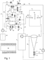
- FIG. 1 shows a block diagram of a possible embodiment of a powder coating system with the powder conveying device 100 according to the invention.
- FIG 2 the basic structure of a possible embodiment of the powder conveying device 100 according to the invention is shown.
- the powder conveying device 100 for conveying coating powder to a powder applicator 4 includes a working container 1. This is designed to be pressure-tight so that it can be pressurized.
- the maximum working pressure in the work container 1 is preferably below 0.5 bar because then the European Pressure Equipment Directive 97/23/EC or Pressure Equipment Directive 97/23/EC does not have to be applied and consequently lower technical requirements are placed on the structure of the work container 1 become.
- the working container 1 comprises a powder inlet 50, which is also referred to as an inlet, and a powder outlet 51.1, which is also referred to as an outlet.
- the powder outlet 51.1 is connected to a powder outlet valve 13.
- a powder line 40 is provided, which is connected to the powder outlet valve 13 at its inlet end region 40.1.
- the term input-side refers to the input-side end region 40.1 of the powder line 40, which is located on the upstream side of the powder line 40.
- the powder line 40 On the input side, the powder line 40 also has an inlet 17 for transport air TL in addition to the connection for the outlet of the powder outlet valve 13.
- the powder line 40 is connected on the output side to a powder applicator 4.
- the term output side refers to the output end region 40.2 of the powder line 40, which is located on the downstream side of the powder line 40.
- the powder outlet 51.1 is preferably located in the lower area of the working container 1. This has the advantage that all of the powder can be easily transported out of the working container 1.
- the fluidizing device 19 has a preferably horizontally extending partition made of a porous material, which can be, for example, a semi-permeable material that is permeable to air.
- the powder located above the porous partition is whirled up with fluidizing air FL passed through the porous partition from below and brought into a suspended state. This process is called fluidizing.
- the fluidized powder located above the fluidizing device 19 can then be transported out of the working container 1 through the powder outlet 51.1.
- a valve 15 In order to be able to control the fluidizing air FL, a valve 15 is provided.
- the valve 15 can be designed, for example, as an air volume control valve.
- a shaking device 20, which has a shaking motor, for example, can be mounted on the work container 1 in order to support the production of a homogeneous powder-air mixture.
- a connection for another valve 14 can also be provided in the lower area of the work container 1. The remaining powder that has not already been transported away via the outlet 51.1 can be removed from the working container 1 via the valve 14.
- a sieve 9 can be arranged in the working container 1, which is preferably designed as an ultrasonic sieve.
- the sieve 9 divides the interior of the work container 1 into an upper chamber and a lower chamber. With the help of the sieve 9, the powder is sieved which has reached the upper chamber of the working container 1 via the powder inlet 50. Clumps of powder and impurities are retained. The powder sifted and ready for transport is located in the chamber below the sieve 9. In order to be able to clean the sieve 9, it can be swiveled out of the horizontal and brought into an inclined position so that the residual powder lying on the sieve 9 and/or the retained material can slide down from the sieve 9 .
- the sieve 9 can also be permanently arranged at a slight angle, as shown in Figure 7 is shown.
- the angle is preferably between 1° and 5° and best of all 3° compared to the horizontal H.
- a hood 110 can be provided above this area and a cleaning connection 1.3 can be provided in the side wall of the working container 1 below the hood 110.
- the hood 110 can be slightly slanted. It forms a slot with the sieve 9 through which air gets under the hood 110 and from there is sucked out of the work container 1 via the cleaning connection 1.3. The air flow causes the contaminants stored on the sieve 9 to be sucked or blown out of the work container 1.
- the cleaning connection 1.3 is connected to the after-filter 8 via the valve 26 and a line 42.
- the valve 26 is opened.
- the work container 1 continues to be supplied with compressed air in order to maintain the excess pressure in the work container 1.
- the accumulated dirt is now blown from the sieve 9 through the line 42 to the secondary filter 8 due to the excess pressure that continues to prevail in the work container 1.
- the cleaning of the sieve 9 therefore preferably takes place during a coating break, i.e. during the time in which no powder is being conveyed.
- the valve 26 and the line 42 therefore serve to discharge dirt.
- a compressed air connection can also be provided on the work container 1, which is connected to a compressed air source via a valve 16.
- compressed air DL can flow into the working container 1.
- the working container 1 to be pressurized and the desired working pressure in the working container 1 to be set.
- the desired working pressure in the working container 1 can also be generated via the supplied fluidizing air FL and the compressed air DL.
- the fluidizing air FL is sufficient to generate the desired working pressure.
- the compressed air DL is also used to maintain the working pressure and, if necessary, to compensate for pressure fluctuations in the working container 1.
- the compressed air DL can be supplied independently of the fluidizing air FL. In order to obtain a well-fluidized powder-air mixture, it is advantageous if the fluidizing air FL is set to a specific value.
- the compressed air connection for the compressed air DL can, for example, as in Figure 1 indicated, be arranged in the upper area of the work container 1.
- the compressed air connection can also be attached to a location on the work container 1, which enables the viewing windows 92 ( Fig. 4 ) can be blown free of the adhering powder.
- Compressed air DL can also be used to compensate for compressed air losses caused by minor leaks.
- the working container 1 can have a vent connection 1.2, which is connected to a valve 12 that serves as a vent valve.
- the ventilation connection 1.2 can be connected to a post-filter 8, for example, via the valve 12.
- the vent connection 1.2 and the valve 12 can also serve to ensure that the pressure in the working container 1 does not exceed a certain maximum pressure.
- the ventilation connection 1.2 and the valve 12 can be used to keep the working pressure in the working container 1 constant.
- the controller 80 ensures that the vent valve 12 opens for a certain short period of time T1 (opening period) and closes for a period of time T2 (closing period).
- the pressure in the working container 1 is measured by means of a pressure sensor 28.1 and if it is determined that the pressure is still too high, the valve 12 is opened again briefly. It can be provided that the opening time T1 and the closing time T2 are chosen to be slightly larger. This process is repeated until the pressure in the working container 1 is again below the maximum pressure Pmax.
- the value Tsetpoint can be, for example, 300 ms.
- the pressure drop in the working container 1 can be kept small.
- the reaction time is short. If the pressure in the working container 1 is below the maximum pressure Pmax, the vent valve 12 remains closed. In addition, the wear of the vent valve 12 can be reduced because the valve is not operated unnecessarily often.
- the controller 80 controls the vent valve 12 using a pulse-coded control signal.
- the pulse-coded control signal can be pulse width or pulse frequency modulated, for example.
- the duty cycle of the pulse-coded control signal corresponds to the time period T for which the vent valve 12 should be open.
- the powder conveying device 100 serves to supply many powder applicators 4, it can happen that the working container 1 is supplied with a large amount of compressed air to maintain the working pressure. If a significant part or all of the powder applicators are switched off at the same time and the supply of fluidizing air FL is not interrupted, it may be that a single vent valve 12 is not sufficient to enable sufficient pressure equalization. It can also be advantageous to provide several of the vent valves 12. These can be constructed like the vent valve 12 and connected in the same way as the vent valve 12.
- the powder inlet 50 is preferably located in the upper area of the working container 1. It can, for example, be arranged in the lid of the working container 1.
- the powder inlet 50 is connected to the powder outlet 2.2 of an intermediate container 2 via a powder valve 11, which is designed, for example, as a squeezer.
- the intermediate container 2 is usually arranged above the working container 1. In this way, gravity can be used to transport powder located in the intermediate container 2 downwards into the working container 1.
- the powder inlet 50 is located in the middle of the lid of the working container 1, as shown in FIG Figure 2 is indicated. This has the advantage that the powder also falls into the middle of the sieve 9, so that it is better distributed over the entire sieve 9.
- the powder inlet 50 can instead also be located on the side of the work container 1 above the sieve 9.
- the intermediate container 2 can also be arranged next to the working container 1 in such a way that the powder outlet 2.2 of the intermediate container 2 and the powder inlet 50 of the working container 1 are still above the sieve 9. Here too, gravity can be used to transport powder in the intermediate container 2 downwards into the working container 1.
- the intermediate container 2 has a powder inlet and a powder inlet valve 21 on the input side, via which fresh powder FP can be sucked or pumped into the intermediate container 2.
- the intermediate container 2 has a further powder inlet and a powder inlet valve 22 on the input side, via which recycled powder RP can be sucked into the intermediate container 2.
- the two powder inlet valves 21 and 22 can be designed as squeezes. However, it is also possible to provide only one powder inlet and one powder inlet valve on the intermediate container 2, via which either fresh powder FP or recycled powder RP can then be sucked in or pumped.
- the intermediate container 2 can be supplied, for example, via a powder storage container 3 and a powder line 46. Instead, the intermediate container 2 can also be supplied with fresh powder FP via a powder storage container 30, a powder pump 31 and a powder line 47.
- the powder storage container 30 is often a so-called big bag, which is also referred to as a flexible intermediate bulk container or FIBC for short.
- the powder storage container 30 usually contains larger amounts of powder than the powder storage container 3.
- the powder storage container 30 is also generally further away from the intermediate container 2 than the powder storage container 3.
- the powder storage container 30 can be at a distance of, for example, 30 m from the intermediate container 2, whereas the powder storage container 3 is, for example, 5m away from the intermediate container 2.
- the powder is conveyed into the intermediate container 2 via the negative pressure prevailing in the intermediate container 2. This means that no additional powder conveying device is necessary and is therefore cost-effective.
- the powder storage container 30 is used, for example in the form of a big bag, larger amounts of powder are usually also conveyed.
- an additional powder conveying device such as the powder pump 31 is used.
- the prevailing negative pressure helps to remove the air from the intermediate container 2.
- the excess air in the intermediate container 2 can be drained through the opening 2.1. This means that there is no back pressure in the intermediate container 2.
- intermediate containers 2 can be mounted above the working container 1.
- these can be operated with a phase offset, for example; While one sucks in powder, i.e. works in the suction phase, the other, which works in the outlet phase, transports the powder into the working container 1. In this way, the working container 2 is continuously filled with powder. This allows large amounts of powder to be conveyed into the work container 2.
- the intermediate container 2 has a connection 2.1, via which the intermediate container 2 can be supplied with compressed air.
- the connection 2.1 can be connected to a compressed air source via a valve 24.
- the valve 24 forms a controllable compressed air source with the compressed air source.
- a pressure control valve 34 which can be arranged between the compressed air source and the valve 24, can be part of the controllable compressed air source.
- connection 2.1 can be connected to the environment via a valve 23.
- the compressed air can also be sucked out of the intermediate container 2 via connection 2.1 and a negative pressure can be generated.
- a vacuum valve 25 is also provided, which is located at the connection 2.1 creates a negative pressure when the valve 23 is open.
- the vacuum valve 25 serves as a vacuum generator.
- the ones shown in the block diagram can be as follows Figure 1
- the compressed air sources shown can be regulated compressed air sources that generate a constant pressure or a constant amount of air.
- All valves 11 to 16, 18 and 21 to 26 can be controlled by means of a control unit 80, which is also referred to below as a controller. If necessary, the valves 71 and 72 can also be controlled with the control 80.
- the control unit 80 can be used for both control and regulation.
- the intermediate container 2 is initially free of powder.
- the valves 11, 21, 22, 24 and 27 are closed so that neither powder gets into the intermediate container 2 nor is powder transported out of the intermediate container 2.
- the valve 23 and the vacuum valve 25 are opened in order to generate a negative pressure in the intermediate container 2.
- the valve 21 or 27 for fresh powder FP or the valve 22 for recycled powder RP is opened, powder is sucked into the intermediate container 2.
- the powder inlet valve 21, 22 or 27 can be opened beforehand.
- the valve 21 or 27 for fresh powder FP or the valve 22 for recycled powder RP is closed again.
- valve 21, 22 or 27 can be open for a certain period of time, for example for 6 seconds.
- the outlet valve 11 is then opened so that the powder can escape from the intermediate container 2. This can be done using gravity.
- compressed air can be blown into the intermediate container 2 via the connection 2.1.
- the valve 24 is opened. Since the working container 1 is permanently under pressure during conveying operation, it is advantageous if the pressure in the intermediate container 2 is greater or at least as great as the pressure in the working container 1.
- a pressure control valve 34 can be used to adjust the pressure. As soon as the powder has come out of the intermediate container 2, the valves 11 and 24 are closed again. The intermediate container 2 can then be filled with powder again in the manner described above.
- the pressure in the intermediate container 2 can also be measured directly in the intermediate container 2. As a result, the actual pressure actually prevailing in the intermediate container 2 is recorded.
- a corresponding pressure control which can be implemented, for example, in the controller 80, it can now be ensured that the actual pressure in the intermediate container 2 actually corresponds to the desired target pressure. If the pressure in the intermediate container 2 is the same as the pressure in the working container 1, there is no pressure drop in the working container 1 when the valve 11 is opened. This ensures uniform powder delivery to the powder applicator even during the time in which the working container 1 is being filled with powder 4 or to the powder applicators.
- the operation of the working container 1 is explained further below.
- the powder valve 11 is opened, the powder comes out of the intermediate container 2 and into the working container 1.
- the powder falls onto the sieve 9, is sieved and trickles from there onto the fluidizing unit 19.
- the valve 18 is opened so that transport air TL flows into the powder line 40. It is advantageous if the valve 18 is permanently open so that the transport air TL can flow continuously into the powder line 40.
- the powder outlet valve 13 is opened, the excess pressure prevailing in the working container 1 ensures that the powder is conveyed out of the working container 1 and via the powder line 40 to the powder applicator 4. This state is also referred to as powder outlet phase A at the working container 1.
- valve 14 While the powder is being conveyed out of the working container 1, the valve 14 is closed. However, if there is a malfunction in the working container 1 during the outlet phase A, for example if the pressure in the working container 1 rises above a certain level, the valve 12 and/or the valves 11 and 22 can be opened.
- the powder outlet valve 13 is temporarily closed or opened for a certain period of time. How long the outlet valve 13 remains open or closed can be specified by the controller 80.
- the controller 80 can, for example, generate a pulse width modulated control signal S that alternates between two values (open or closed or 0 or 1).
- TPWM is the period of the control signal S
- Tein is the width of the control pulse.
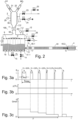
- FIG 3a A pulse width modulated control signal S is shown as an example over time t.
- the outlet valve 13 is therefore open for the period T on, so that powder can flow through the outlet valve 13 for the period T on.
- Figure 3b shows the time course of the air pressure p(TL) of the transport air TL. In the present example, p(TL) is constant.
- Figure 3c Finally, an example diagram shows the amount of powder Q conveyed per time at the outlet 40.2 of the powder line 40. It can be seen that - even if the outlet valve 13 is temporarily closed - powder is still conveyed.
- the amount of powder to be conveyed can be set between 30 and 2000 g/min.
- the powder conveying device 100 can also be adapted so that powder quantities of 10 to 5000 g/min can be conveyed. In one tested embodiment, the powder could be conveyed over a distance of between 5 and 30m.
- the powder conveying device 100 can also be adapted so that the powder can be conveyed over distances of 1m to 50m.
- Powder lines 40 with an inner diameter of 3 to 30 mm can be used for this purpose. In the tested embodiment, various hoses with inner diameters between 8 and 12 mm were used. However, you can also use standard hoses with an inner diameter of 6 to 14 mm.
- the inner diameter of the powder line 40 is selected based on the amount of powder to be conveyed. For smaller quantities of powder, a powder line with a smaller inner diameter is usually sufficient.
- the transport air TL can be set in a range of 0.1 to 50 Nm3/h (standard cubic meters per hour) or 0.5 to 6 Nm3/h.
- the transport air TL can be set in a pressure range of 0.1 to 10 bar.
- the inside diameter of the squeeze is preferably in a range of 3 to 10 mm, more preferably between 3 to 5 mm.
- the total cycle time is preferably in a range of 100 to 300 ms.
- the pulse width can preferably be set in a range from 5 to 90 or 290 ms.
- the flow speed of the powder stream can be adjusted via the pressure p(TL) of the transport air TL.
- a fast powder cloud is advantageous if it needs to penetrate far into the workpiece. This is helpful, for example, for a workpiece with a large depression.
- the workpiece is relatively flat, a soft and therefore slow powder cloud is used. This means that the powder cloud can be ideally adapted to the geometry of the workpiece to be coated via the flow speed of the powder.
- the flow speed can be adjusted to the type of powder used (grain size, adhesion, etc.). Overall, this leads to optimized application efficiency. It can be ensured that powder can be conveyed consistently over a long period of time, i.e. process-reliably, reproducibly and with little wear. Organic powder types and also inorganic powder types, such as enamel, can be conveyed.
- a pulse width modulated control signal S instead of a pulse width modulated control signal S, a pulse frequency or pulse density modulated control signal S can also be used.
- the pulse frequency modulated control signal S With the pulse frequency modulated control signal S, the pulse width T in of the individual pulses is constant over time. The lower the pulse density, the lower the quantity of powder Q conveyed per unit of time. If the pulse density is 1, the maximum quantity of powder Q to be conveyed is reached.
- pulse-coded control signals S are used to set the amount of powder Q to be conveyed.
- the term pulse-coded should be understood here as the conversion of any numerical value into a binary pulse sequence.
- Figure 4 shows a further possible embodiment of the powder conveying device 100 according to the invention in a three-dimensional view.
- Figure 5 shows the further embodiment of the powder conveying device 100 according to the invention in a longitudinal section.
- the working container 1 n has powder outlets 51.1 - 51.n, each of the powder outlets 51.1 - 51.n being connected to a respective powder outlet valve 13.1 to 13.n.
- a powder line 40 and a powder applicator can be connected to each of the powder outlet valves 13.1 to 13.n.
- the control 80 can be designed so that each of the powder outlet valves 13.1 to 13.n can be controlled separately. This achieves a high degree of flexibility.
- the applicator that is connected to the powder outlet valve 13.1 can be switched off by leaving the powder outlet valve 13.1 permanently closed, while the applicator that is connected to the powder outlet valve 13.2 is switched on by controlling the powder outlet valve 13 accordingly. It is also possible to supply the individual applicators with different amounts of powder by controlling the respective outlet valves 13 differently. In addition, the individual applicators can also generate powder clouds at different speeds by opening the valves 18 for the transport air TL accordingly different transport air quantities can be set. It is also possible to use powder lines 40 of different lengths, whereby the differences in length between the powder lines can be compensated for by appropriate, individual control of the outlet valves 13.
- a tilting mechanism 91 is provided on the work container 1.
- a closure 90 is provided in order to be able to open the lid of the work container 1.
- One or more viewing windows 92 can be arranged in the lower area of the work container 1. It can be provided that there is a further viewing window and a light source in the work container 1 on the opposite side of the viewing window 92. This makes it possible to visually record the powder level in the working container 1 during operation without having to open the working container 1. Visual detection can be done using sensors or by operating personnel.
- a capacitive sensor 28.2 is arranged in the area of the upper chamber on the working container 1.
- the sensor 28.2 can be arranged, for example, on the lid 93 of the work container 1. It can be used to detect the fill level in the upper chamber of the working container 1, transmit it to the controller 80 and evaluate it there.
- the controller 80 can thus determine whether enough powder is trickling through the sieve 9 or whether the sieve 9 is clogged. If necessary, the controller 80 can react accordingly, for example with a warning for the operating personnel.
- a further capacitive sensor 28.3 is arranged below the sieve. With it, the fill level in the upper chamber of the working container 1 can be detected and transmitted to the controller 80. The controller 80 can evaluate the sensor signal and is therefore able to determine whether there is too much powder or too little powder in the upper chamber and can react to this, for example by issuing a warning to the operating personnel.
- a capacitive sensor 28.4 is arranged in the area of the lower chamber on the working container 1.
- capacitive sensors 28.3 and 28.4 instead of the capacitive sensors 28.3 and 28.4, other sensors can also be used if they are suitable for measuring the fill level.
- a connection 35.1 is provided in the area from the sensor 28.3 to the lid 93 of the working container 1, i.e. in the non-fluidized area.
- a connection 35.2 is provided between the bottom of the working container 1 and the sensor 28.4, so that the connection 35.2 is always in the fluidized area.
- a differential pressure sensor 35 for detecting the difference between the pressure in the upper and the pressure in the lower chamber can be connected to the two connections 35.1 and 35.2.
- the differential pressure signal generated by the differential pressure sensor 35 can be transmitted to the controller 80.
- the controller 80 can determine the exact filling level from the differential pressure.
- the level in the lower chamber of the working container 1 can be calibrated.
- the powder output quantities can be determined for each powder outlet valve 13.1 to 13.n using several reference measurements with different settings. This means that level measurements can also be carried out during operation.
- powder is prevented from passing from the intermediate container 2 into the working container 1 for a certain period of time.
- the total amount of powder that was conveyed by the powder outlet valves 13.1 to 13.x used in a certain period of time is then determined.
- the controller 80 checks whether the total amount of powder is within a certain range. If this is not the case, the controller 80 can issue a message.
- refer to the patent EP 1092958 B1 known methods for determining a quantity of powder or a change in the quantity of powder in a container are referred to. Their content is hereby included in the registration.
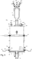
- Figure 5 shows a possible embodiment of the intermediate container 2 in a longitudinal section.
- a semi-permeable wall 95 which is permeable to air but impermeable to powder.
- air can be sucked out of the intermediate container 2 via the connection 2.1 and the valve 24 connected to it and a negative pressure can be generated.
- the semi-permeable wall 95 ensures that the powder sucked into the intermediate container 2 cannot be sucked out via the connection 2.1. If compressed air is pressed into the intermediate container 2 through the valve 24 and the connection 2.1, it can flow through the semi-permeable wall 95 and generate excess pressure in the intermediate container 2.
- the valve 11 is opened, the compressed air can also be used to clear the wall 95 of any powder deposited there.
- FIG. 6 shows a possible embodiment of the powder outlet valve 13 in section.
- the outlet valve 13 includes a valve body 96 and an inlet body 101, both of which can be attached to the work container 1 with screws 102.
- the valve body 96 is inserted into a correspondingly designed receptacle 1.1 on the work container 1. So that the channel in the working container 1 for the powder outlet 51.1 is as short as possible, the receptacle 1.1 is as in Figure 6 shown, sunk into the work container 1 and designed as a blind hole. However, this does not necessarily have to be the case.
- the upstream end section 97.1 of the squeezer 97 can also be in the Recording 1.1 must be placed. This has the advantage that the squeezer 97 is positioned correctly. However, this does not necessarily have to be the case.
- the valve 13 also includes a valve control connection block 99, which can be designed, for example, as an electro-pneumatic quick-switching valve. This advantageously has a short switching time and a short reaction time.
- the valve control connection block 99 is connected to the corresponding control output of the controller 80 via an electrical control cable, not shown. The controller 80 can thus cause the valve 13 to be opened or closed via the control signal S.
- Inside the valve body 96 there is a hose squeezer 97, the passage of which - depending on the compressed air control signal S - is either open or closed. In the compressed air-free state, the hose squeezer 97 is relaxed and its passage is opened. The outside of the hose squeezer 97 then lies against the inside of the ring 98.
- the ring 98 ensures that - regardless of the pressure in the work container 1 - the opening width of the hose squeezer 97 remains the same and is defined in the compressed air-free state. This ensures a reproducible opening width of the valve 13.
- the ring 98 can be made of plastic, for example. This structure has the advantage that the pressure in the working container 1 helps to open the hose squeezer 97. With a powder conveyor that has to open the squeezer even under negative pressure, this can lead to problems over time.
- a control valve is provided, which is arranged in the control connection block 99.
- a so-called normally open valve is advantageously used as the control valve in the control connection block 99. If the control 80 fails, i.e. if there is no control signal S at the control valve, the normally open valve is opened, so that the squeeze 97 of the valve 13 is closed.
- the inlet 17 directly adjoins the valve 13, this has the advantage that the supplied transport air TL can mix with the conveyed powder essentially over the entire length of the powder line 40. However, such an arrangement is not absolutely necessary.
- the inlet 17 can also be located somewhat further downstream on the powder line 40.
- the inlet body 101 with the inlet 17 for the transport air TL has an axially extending air channel 32 which annularly surrounds the downstream end region of the powder channel 96.2 of the valve body 96.
- the inlet body 101 can be designed as a hose nipple 33 on the outside in its downstream end region.
- the powder line 40 or the powder hose can be pushed onto the hose nipple 33 and fastened.
- a hose coupling, for example with a snap connection, is also conceivable here (not shown in the figures).
- the inside of the hose nipple 33 and the outside of the powder channel 96.2 form an annular transport air channel 32.
- the downstream end of the hose nipple 33 and the powder channel 96.2 form an annular gap 94, which serves as a downstream opening of the transport air channel 32.
- a transverse bore is provided in the inlet body 101.
- the transport air TL flows through the transport air channel 32 to its downstream end and from there in a ring shape and at a flat angle ⁇ into the powder line 40.
- Allowing the transport air TL to flow into the powder line 40 via the annular gap 94 has several advantages. Because the transport air TL is introduced into the powder line 40 through the annular gap 94 in such a way that it has the same direction as the main flow, a negative pressure is generated at the inlet 17 rather than a dynamic pressure (no air resistance, no barrier). This creates less turbulence in the powder line 40. In addition, the wear on the wall of the powder line 40 can be reduced or even completely avoided.
- the inlet body 101 can, for example, have one or more channels through which the transport air TL is introduced into the powder line 40 at an angle between 0 and 89 degrees.
- the transport air TL flowing through the channels tends to create a negative pressure in the powder line 40.
- inlet body 101 it is also possible to design the inlet body 101 in such a way that the transport air TL flows into the powder line 40 at a 90 degree angle or greater than 90 degrees.
- the inlet body 101 can also be designed such that the transport air TL flows into the powder line 40 via a filter tube made of microporous material.
- valve 18 for the transport air TL is closed briefly during the outlet phase A, so that no transport air TL is introduced into the powder line 40 for a short time. This further reduces the influence of the transport air TL on the quantity of powder Q delivered.
- the powder channel 96.2 of the valve body 96 can be conical on the downstream side of the valve 13.
- the powder line 40 can be designed entirely or partially as a hose.
- the powder coating system can, as in Figure 1 shown, in addition to the powder conveying device 100 and the coating booth 6 also have a cyclone 7 for recovering the powder and a post-filter 8.
- the cyclone 7 which can be designed as a monocyclone.
- the powder-air mixture flows tangentially into the cyclone 7 at the top and spirals downwards in the cyclone.
- the centrifugal force created by the rotation of the powder air flow pushes the powder particles outwards onto the outer wall of the cyclone.
- the powder particles are then conveyed downwards towards the powder outlet of the cyclone and collected there.
- the air freed from the powder particles is sucked out via a central tube in the cyclone.
- the air stream cleaned in this way can still be fed to the after-filter 8 in order to filter out the remaining powder remaining in the air.
- the valve 71 When the valve 71 is opened, the recycled powder RP can be removed from the cyclone 7 and fed back to the powder conveying device 100 via a pump 73 and a line 41.
- the valve 72 When the valve 72 is opened, the powder filtered out in the cyclone can also be fed to the after-filter 8 via lines 45 and 44.
- the post-filter 8 can be equipped with filter cartridges that filter out the remaining powder particles remaining in the air.
- a preferably electrically driven fan or blower ensures the necessary air flow.
- the powder can also be removed from the secondary filter 8 and fed back to the powder conveying device 100 via the pump 73 and the line 41.
Description
Die Erfindung betrifft eine Pulverfördervorrichtung zum Fördern von Beschichtungspulver zu einem Pulverapplikator. Die Erfindung betrifft zudem eine Pulverbeschichtungsanlage und ein Verfahren zum Betreiben der Pulverfördervorrichtung. Als Pulverapplikator oder kurzum als Applikator kann zum Beispiel eine manuelle oder eine automatische Pulversprühpistole dienen.The invention relates to a powder conveying device for conveying coating powder to a powder applicator. The invention also relates to a powder coating system and a method for operating the powder conveying device. A manual or automatic powder spray gun, for example, can serve as a powder applicator or in short as an applicator.
Aus dem Stand der Technik
Diese Lösung hat den Nachteil, dass der maximal mögliche Druck der Triggerluft während des Förderbetriebs kleiner als der im Pulverreservoir herrschende Druck sein muss. Andernfalls würde der Reinigungsbetrieb gestartet werden.This solution has the disadvantage that the maximum possible pressure of the trigger air during conveying operation must be smaller than the pressure prevailing in the powder reservoir. Otherwise the cleaning operation would be started.
Ein weiterer Nachteil bei dieser Lösung ist, dass der Druck der Triggerluft sowohl die Pulvermenge als auch die Strömungsgeschwindigkeit des Pulvers beeinflusst. Wenn über die Triggerluft die Pulver-Durchflussmenge verändert wird, hat dies zwangsläufig auch eine Veränderung der Strömungsgeschwindigkeit zur Folge. Über die Triggerluft kann folglich immer nur die Pulver-Durchflussmenge zusammen mit der Strömungsgeschwindigkeit einstellt werden. Über die Triggerluft kann hingegen nicht oder nur sehr ungenau eingestellt werden, wie schnell sich die vom Applikator erzeugte Pulverwolke ausbreiten soll. Eine separate Einstellung der Strömungsgeschwindigkeit unabhängig von der Pulvermenge ist nicht möglich.Another disadvantage of this solution is that the pressure of the trigger air influences both the amount of powder and the flow rate of the powder. If the powder flow rate is changed via the trigger air, this inevitably also results in a change in the flow speed. The trigger air can therefore only be used to adjust the powder flow rate together with the flow speed. However, the trigger air cannot be used to set how quickly the powder cloud generated by the applicator should spread, or only very imprecisely. A separate adjustment of the flow rate regardless of the amount of powder is not possible.
Aus dem Stand der Technik
Eine Aufgabe der Erfindung ist es, eine Pulverfördervorrichtung zum Fördern von Beschichtungspulver zu einem Pulverapplikator, eine Pulverbeschichtungsanlage und ein Betriebsverfahren anzugeben, bei denen die im Stand der Technik vorhandenen Nachteile vermieden werden.An object of the invention is to provide a powder conveying device for conveying coating powder to a powder applicator, a powder coating system and an operating method in which the disadvantages present in the prior art are avoided.
Vorteilhafter Weise ist bei der erfindungsgemässen Pulverfördervorrichtung die Strömungsgeschwindigkeit des durch die Pulverleitung strömenden Pulvers beziehungsweise die Strömungsgeschwindigkeit der vom Applikator erzeugen Pulverwolke im Wesentlichen unabhängig von der geförderten Pulvermenge einstellbar. Sinngemäss das Gleiche gilt auch für die Pulverbeschichtungsanlage und das Betriebsverfahren.Advantageously, in the powder conveying device according to the invention, the flow velocity of the powder flowing through the powder line or the flow velocity of the powder cloud generated by the applicator can be adjusted essentially independently of the amount of powder conveyed. The same applies to the powder coating system and the operating process.
Die Aufgabe wird durch eine Pulverfördervorrichtung zum Fördern von Beschichtungspulver zu einem Pulverapplikator mit den in Patentanspruch 1 angegebenen Merkmalen gelöst.The object is achieved by a powder conveying device for conveying coating powder to a powder applicator with the features specified in
Die erfindungsgemässe Pulverfördervorrichtung zum Fördern von Beschichtungspulver zu einem Pulverapplikator umfasst einen Arbeitsbehälter, der so ausgebildet und betreibbar ist, dass er unter Druck setzbar ist. Der Arbeitsbehälter umfasst zudem einen Pulvereinlass und einen Pulverauslass, wobei der Pulverauslass mit einem Pulverauslassventil verbunden ist. Darüber hinaus ist eine Pulverleitung vorgesehen, die eingangsseitig mit dem Pulverauslassventil verbunden ist, und die eingangsseitig einen Einlass für Transportluft aufweist. Die Pulverleitung ist ausgangsseitig mit einem Pulverapplikator verbindbar. Zudem ist eine Steuerung vorgesehen, die derart ausgebildet und betreibbar ist, dass sie die zu fördernde Pulvermenge steuert, indem sie das Pulverauslassventil wiederholt öffnet und schliesst.The powder conveying device according to the invention for conveying coating powder to a powder applicator comprises a working container which is designed and operable in such a way that it can be pressurized. The working container also includes a powder inlet and a powder outlet, the powder outlet being connected to a powder outlet valve. In addition, a powder line is provided, which is connected on the input side to the powder outlet valve and which has an inlet for transport air on the input side. The powder line can be connected to a powder applicator on the output side. In addition, a control is provided which is designed and operable in such a way that it controls the amount of powder to be conveyed by repeatedly opening and closing the powder outlet valve.
Darüber hinaus wird die Aufgabe durch eine Pulverbeschichtungsanlage mit den in Patentanspruch 15 angegebenen Merkmalen gelöst.In addition, the task is achieved by a powder coating system with the features specified in
Die erfindungsgemässe Pulverbeschichtungsanlage umfasst die oben beschriebene Pulverfördervorrichtung, wobei die Pulverfördervorrichtung einerseits mit einem Pulvervorratsbehälter und andererseits mit einer oder mehreren Pulverapplikatoren verbunden ist.The powder coating system according to the invention comprises the powder conveying device described above, the powder conveying device being connected on the one hand to a powder storage container and on the other hand to one or more powder applicators.
Darüber hinaus wird die Aufgabe durch ein Verfahren zum Betreiben der oben beschriebenen Pulverfördervorrichtung mit den in Patentanspruch 16 angegebenen Merkmalen gelöst.In addition, the object is achieved by a method for operating the powder conveying device described above with the features specified in
Bei dem erfindungsgemäßen Verfahren zum Betreiben der oben beschriebenen Pulverfördervorrichtung erfolgt die die Pulverförderung dadurch, dass Transportluft in die Pulverleitung geleitet wird, und dass mittels der Steuerung das Auslassventil mittels eines pulscodierten Steuersignals wiederholt geöffnet und geschlossen wird. Über das Verhältnis zwischen der Zeitdauer, in der das Auslassventil geschlossen ist und der Zeitdauer, in der das Auslassventil geöffnet ist, wird die zu fördernde Pulvermenge eingestellt.In the method according to the invention for operating the powder conveying device described above, the powder is conveyed by passing transport air into the powder line and by repeatedly opening and closing the outlet valve by means of the controller using a pulse-coded control signal. The amount of powder to be conveyed is set via the ratio between the period of time in which the outlet valve is closed and the period of time in which the outlet valve is open.
Vorteilhafte Weiterbildungen der Erfindung ergeben sich aus den in den abhängigen Patentansprüchen angegebenen Merkmalen.Advantageous developments of the invention result from the features specified in the dependent patent claims.
Bei einer Ausführungsform der erfindungsgemässen Pulverfördervorrichtung ist die Steuerung derart ausgebildet und betreibbar, dass sie zur Steuerung der zu fördernden Pulvermenge das Pulverauslassventil mittels einer Pulsweitenmodulation oder einer Pulsfrequenzmodulation ansteuert.In one embodiment of the powder conveying device according to the invention, the control is designed and operable in such a way that it controls the powder outlet valve by means of pulse width modulation or pulse frequency modulation to control the amount of powder to be conveyed.
Erfindungsgemäß ist bei der Pulverfördervorrichtung ein Drucksensor vorgesehen, um den Druck im Arbeitsbehälter zu erfassen. Die Steuerung ist derart ausgebildet und betreibbar, dass sie den Druck im Arbeitsbehälter regelt.According to the invention, a pressure sensor is provided in the powder conveying device in order to detect the pressure in the working container. The control is designed and operable in such a way that it regulates the pressure in the work container.
Bei einer Weiterbildung der erfindungsgemässen Pulverfördervorrichtung ist der Einlass für Transportluft unmittelbar nach dem Pulverauslassventil vorgesehen.In a further development of the powder conveying device according to the invention, the inlet for transport air is provided immediately after the powder outlet valve.
Bei einer zusätzlichen Weiterbildung der erfindungsgemässen Pulverfördervorrichtung ist der Einlass für die Transportluft als Ringspalt ausgebildet. Die Transportluft mittels eines Ringspalts in die Pulverleitung einströmen zu lassen hat mehrere Vorteile. Weil die Transportluft durch den Ringspalt so in die Pulverleitung eingeleitet wird, dass sie die gleiche Richtung wie der Hauptstrom aufweist, wird dort, wo die Transportluft eingeleitet wird, eher ein Unterdruck erzeugt als ein Staudruck (kein Luftwiderstand, keine Barriere). Dadurch entstehen weniger Turbulenzen in der Pulverleitung. Zudem lässt sich der Verschleiss an der Wandung der Pulverleitung reduzieren oder sogar gänzlich vermeiden.In an additional development of the powder conveying device according to the invention, the inlet for the transport air is designed as an annular gap. Allowing the transport air to flow into the powder line via an annular gap has several advantages. Because the transport air is introduced into the powder line through the annular gap in such a way that it has the same direction as the main flow, a negative pressure is created where the transport air is introduced rather than a dynamic pressure (no air resistance, no barrier). This creates less turbulence in the powder line. In addition, wear on the wall of the powder line can be reduced or even completely avoided.
Bei einer anderen Weiterbildung der erfindungsgemässen Pulverfördervorrichtung ist der Einlass für Transportluft so ausgebildet, dass die Transportluft in einem spitzen Winkel in die Pulverleitung einblasbar ist.In another development of the powder conveying device according to the invention, the inlet for transport air is designed such that the transport air can be blown into the powder line at an acute angle.
Zudem kann bei der erfindungsgemässen Pulverfördervorrichtung eine Dosiereinrichtung für die Transportluft vorgesehen sein. Als Dosiereinrichtung kann zum Beispiel ein Luftmengenregel-Ventil dienen.In addition, a metering device for the transport air can be provided in the powder conveying device according to the invention. An air volume control valve, for example, can serve as a metering device.
Darüber hinaus kann bei der erfindungsgemässen Pulverfördervorrichtung eine Fluidisiereinrichtung vorgesehen sein. Die Fluidisiereinrichtung ist vorzugsweise im unteren Bereich des Arbeitsbehälters angeordnet.In addition, a fluidizing device can be provided in the powder conveying device according to the invention. The fluidizing device is preferably arranged in the lower region of the work container.
Es ist von Vorteil, wenn bei der erfindungsgemässen Pulverfördervorrichtung der Arbeitsbehälter einen weiteren Pulverauslass aufweist, und eine weitere Pulverleitung vorgesehen ist. Die weitere Pulverleitung ist eingangsseitig mit einem weiteren Pulverauslassventil und einem weiteren Einlass für Transportluft verbunden. Ausgangsseitig ist die weitere Pulverleitung mit einem weiteren Pulverapplikator verbindbar. Damit können mit der erfindungsgemässen Pulverfördervorrichtung mehrere Pulverapplikatoren mit Pulver versorgt werden. Zudem können die einzelnen Pulverapplikatoren unabhängig voneinander und bei Bedarf jeweils mit unterschiedlich viel Pulver versorgt werden.It is advantageous if, in the powder conveying device according to the invention, the working container has a further powder outlet and a further powder line is provided. The additional powder line is connected on the input side to another powder outlet valve and another inlet for transport air. On the output side, the additional powder line can be connected to another powder applicator. This means that several powder applicators can be supplied with powder using the powder conveying device according to the invention. In addition, the individual powder applicators can be supplied independently of each other and with different amounts of powder if required.
Zudem ist es von Vorteil, wenn bei der erfindungsgemässen Pulverfördervorrichtung der Arbeitsbehälter ein Entlüftungsventil aufweist. Das Entlüftungsventil ist primär Teil einer Regeleinrichtung, mit der der Druck im Arbeitsbehälter geregelt werden kann. Das Entlüftungsventil kann auch als Sicherheitsventil dienen. Im Störfall kann damit vermieden werden, dass der Druck im Inneren des Arbeitsbehälters einen maximal zulässigen Grenzwert überschreitet.It is also advantageous if the working container in the powder conveying device according to the invention has a vent valve. The vent valve is primarily part of a control device with which the pressure in the working container can be regulated. The vent valve can also serve as a safety valve. In the event of a fault, this can prevent the pressure inside the working container from exceeding a maximum permissible limit.
Die erfindungsgemässe Pulverfördervorrichtung kann ein Ultraschallsieb aufweisen, das im Arbeitsbehälter angeordnet ist.The powder conveying device according to the invention can have an ultrasonic sieve which is arranged in the working container.
Es ist auch möglich, dass die erfindungsgemässe Pulverfördervorrichtung einen Zwischenbehälter aufweist, der über ein Ventil mit dem Pulvereinlass des Arbeitsbehälters verbunden ist. Mittels eines Unterdruckerzeugers kann Pulver in den Zwischenbehälter gesaugt werden. Damit kann der Arbeitsbehälter bei Bedarf permanent über den Zwischenbehälter mit Pulver versorgt werden. Auf diese Weise wird eine dauerhafte und unterbrechungsfreie Versorgung der Pulverapplikatoren ermöglicht.It is also possible for the powder conveying device according to the invention to have an intermediate container which is connected to the powder inlet of the working container via a valve. Using a vacuum generator, powder can be sucked into the intermediate container. This means that the work container can be permanently supplied with powder via the intermediate container if necessary. This enables a permanent and uninterrupted supply of the powder applicators.
Bei der erfindungsgemässen Pulverfördervorrichtung kann eine steuerbare Druckluftquelle vorgesehen sein, die mit dem Zwischenbehälter verbunden ist, und mit der der Zwischenbehälter unter Druck setzbar ist. Damit kann der Zwischenbehälter auf ein Druckniveau gebracht werden, das demjenigen des Arbeitsbehälters entspricht, sodass keine Druckdifferenz zwischen dem Arbeitsbehälter und Zwischenbehälter besteht. Dadurch kann eine Ursache für Druckschwankungen im Arbeitsbehälter eliminiert werden. Dies wiederum hat den Vorteil, dass die Druckschwankungen im Arbeitsbehälter und damit auch die Druckschwankungen beim Applikator und die Schwankungen bei der zum Applikator geförderten Pulvermenge reduziert werden können. Die Qualität des Pulverapplizierens lässt sich auf diese Weise weiter optimieren.In the powder conveying device according to the invention, a controllable compressed air source can be provided which is connected to the intermediate container and with which the intermediate container can be pressurized. This allows the intermediate container to be brought to a pressure level that corresponds to that of the working container, so that there is no pressure difference between the working container and the intermediate container. This can eliminate a cause of pressure fluctuations in the work vessel. This in turn has the advantage that the pressure fluctuations in the working container and thus also the pressure fluctuations in the applicator and the fluctuations in the amount of powder conveyed to the applicator can be reduced. The quality of powder application can be further optimized in this way.
Bei einer Ausführungsform der erfindungsgemässen Pulverfördervorrichtung ist der Zwischenbehälter oberhalb des Arbeitsbehälters angeordnet. Dies hat den Vorteil, dass die Schwerkraft benutzt werden kann, um das Pulver in den Arbeitsbehälter zu transportieren.In one embodiment of the powder conveying device according to the invention, the intermediate container is arranged above the working container. This has the advantage that gravity can be used to transport the powder into the work container.
Vorteilhafter Weise wird bei dem Verfahren zum Betreiben der Pulverfördervorrichtung die Transportluft während der Pulverförderung ununterbrochen in die Pulverleitung geleitet.Advantageously, in the method for operating the powder conveying device, the transport air is continuously fed into the powder line during powder conveying.
Im Folgenden wird die Erfindung mit mehreren Ausführungsbeispielen anhand von sieben Figuren weiter erläutert.
Figur 1- zeigt in einem Blockdiagramm eine mögliche Ausführungsform einer Pulverbeschichtungsanlage mit der erfindungsgemässen Pulverfördervorrichtung.
Figur 2- zeigt in einer Prinzipdarstellung eine mögliche Ausführungsform der erfindungsgemässen Pulverfördervorrichtung.
- Figur 3a
- zeigt in einem Diagramm den zeitlichen Verlauf des Steuersignals für das Pulver-Auslassventil.
- Figur 3b
- zeigt in einem Diagramm den zeitlichen Verlauf des eingespeisten Transportluftdrucks.
- Figur 3c
- zeigt in einem Diagramm die pro Zeit geförderte Pulvermenge.
Figur 4- zeigt eine mögliche Ausführungsform der erfindungsgemässen Pulverfördervorrichtung in einer dreidimensionalen Ansicht.
Figur 5- zeigt die erfindungsgemässe Pulverfördervorrichtung im Längsschnitt.
Figur 6- zeigt eine mögliche Ausführungsform eines Auslassventils im Schnitt.
Figur 7- zeigt eine mögliche Anordnung einer Haube zum Schmutzaustrag in der erfindungsgemässen Pulverfördervorrichtung.
- Figure 1
- shows a possible embodiment of a powder coating system with the powder conveying device according to the invention in a block diagram.
- Figure 2
- shows a schematic representation of a possible embodiment of the powder conveying device according to the invention.
- Figure 3a
- shows a diagram of the time course of the control signal for the powder outlet valve.
- Figure 3b
- shows the time course of the transport air pressure fed in in a diagram.
- Figure 3c
- shows the amount of powder conveyed per time in a diagram.
- Figure 4
- shows a possible embodiment of the powder conveying device according to the invention in a three-dimensional view.
- Figure 5
- shows the powder conveying device according to the invention in a longitudinal section.
- Figure 6
- shows a possible embodiment of an exhaust valve in section.
- Figure 7
- shows a possible arrangement of a hood for discharging dirt in the powder conveying device according to the invention.
In einer Ausführungsform umfasst der Arbeitsbehälter 1 einen Pulvereinlass 50, der auch kurzum als Einlass bezeichnet wird, und einen Pulverauslass 51.1, der auch kurzum als Auslass bezeichnet wird. Der Pulverauslass 51.1 ist mit einem Pulverauslassventil 13 verbunden. Darüber hinaus ist eine Pulverleitung 40 vorgesehen, die an ihrem eingangsseitigen Endbereich 40.1 mit dem Pulverauslassventil 13 verbunden ist. Im Folgenden bezeichnet der Begriff eingangsseitig den eingangsseitigen Endbereich 40.1 der Pulverleitung 40, der sich auf der stromaufwärtigen Seite der Pulverleitung 40 befindet.In one embodiment, the working
Die Pulverleitung 40 weist eingangsseitig zusätzlich zum Anschluss für den Auslass des Pulverauslassventils 13 auch einen Einlass 17 für Transportluft TL auf. In
Der Pulverauslass 51.1 befindet sich vorzugsweise im unteren Bereich des Arbeitsbehälters 1. Dies hat den Vorteil, dass das gesamte Pulver ohne weiteres aus dem Arbeitsbehälter 1 heraustransportiert werden kann. Im unteren Bereich des Arbeitsbehälters 1 befindet sich auch eine Fluidisiereinrichtung 19, mit der das im Arbeitsbehälter 1 befindliche Pulver fluidisiert werden kann. Die Fluidisiereinrichtung 19 weist eine vorzugsweise horizontal verlaufende Trennwand aus einem porösem Material auf, das zum Beispiel ein semipermeables, für Luft durchlässiges Material sein kann. Das oberhalb der porösen Trennwand befindliche Pulver wird mit von unten durch die poröse Trennwand hindurchgeleiteter Fluidisierluft FL aufgewirbelt und in einen Schwebezustand versetzt. Dieser Vorgang wird als fluidisieren bezeichnet. Das oberhalb der Fluidisiereinrichtung 19 befindliche fluidisierte Pulver kann dann aus dem Arbeitsbehälter 1 durch den Pulverauslass 51.1 heraustransportiert werden. Um die Fluidisierluft FL steuern zu können, ist ein Ventil 15 vorgesehen. Das Ventil 15 kann zum Beispiel als Luftmengenregel-Ventil ausgebildet sein. Zudem kann eine Rüttelvorrichtung 20, die zum Beispiel einen Rüttelmotor aufweist, am Arbeitsbehälter 1 montiert sein, um die Erzeugung eines homogenen Pulver-Luft-Gemisches zu unterstützen.The powder outlet 51.1 is preferably located in the lower area of the working
Ebenfalls im unteren Bereich des Arbeitsbehälters 1 kann ein Anschluss für ein weiteres Ventil 14 vorgesehen sein. Über das Ventil 14 kann das Restpulver, das nicht bereits über den Auslass 51.1 abtransportiert wurde, aus dem Arbeitsbehälter 1 entnommen werden.A connection for another
Des Weiteren kann im Arbeitsbehälter 1 ein Sieb 9 angeordnet sein, das vorzugsweise als Ultraschall-Sieb ausgebildet ist. Das Sieb 9 teilt den Innenraum des Arbeitsbehälters 1 in eine obere Kammer und in eine untere Kammer. Mit Hilfe des Siebs 9 wird das Pulver gesiebt, das über den Pulvereinlass 50 in die obere Kammer des Arbeitsbehälter 1 gelangt ist. Dabei werden Pulverklumpen und Verunreinigungen zurückgehalten. Das gesiebte und zum Abtransport bereite Pulver befindet sich in der Kammer unterhalb des Siebs 9. Um das Sieb 9 reinigen zu können, kann es aus der Horizontale herausgeschwenkt und in eine Schräglage gebracht werden, sodass das auf dem Sieb 9 liegende Restpulver und/oder das zurückgehaltene Material vom Sieb 9 herunterrutschen kann.Furthermore, a
Stattdessen kann das Sieb 9 auch andauernd leicht schräg angeordnet sein, wie dies in
Am Arbeitsbehälter 1 kann zudem ein Druckluftanschluss vorgesehen sein, der über ein Ventil 16 mit einer Druckluftquelle verbunden ist. Wenn das Ventil 16 geöffnet ist, kann Druckluft DL in den Arbeitsbehälter 1 strömen. Damit kann der Arbeitsbehälter 1 unter Druck gesetzt und der gewünschte Arbeitsdruck im Arbeitsbehälter 1 eingestellt werden. Stattdessen kann der gewünschte Arbeitsdruck im Arbeitsbehälter 1 auch über die zugeführte Fluidisierluft FL und über die Druckluft DL erzeugt werden. In der Regel reicht die Fluidisierluft FL aus, um den gewünschten Arbeitsdruck zu erzeugen. Wenn jedoch zum Beispiel sehr viele Pulverauslassventile 13 geöffnet sind, könnte es sein, dass die Fluidisierluft FL allein nicht ausreicht, um den Arbeitsdruck aufrecht zu erhalten. In diesem Fall wird zusätzlich die Druckluft DL benutzt, um den Arbeitsdruck aufrecht zu erhalten und um gegebenenfalls Druckschwankungen im Arbeitsbehälter 1 auszugleichen. Die Druckluft DL kann unabhängig von der Fluidisierluft FL zugeführt werden. Um ein gut fluidisiertes Pulver-Luft-Gemisch zu erhalten, ist es von Vorteil, wenn die Fluidisierluft FL auf einen bestimmten Wert eingestellt ist. Der Druckluftanschluss für die Druckluft DL kann zum Beispiel, wie in
Im Folgenden wird ein mögliches Verfahren zur Entlüftung beschrieben. Bei Überschreitung eines bestimmten maximalen Drucks Pmax sorgt die Steuerung 80 dafür, dass das Entlüftungsventil 12 für eine bestimmte kurze Zeitdauer T1 (Öffnungszeitdauer) öffnet und für eine Zeitdauer T2 (Schliesszeitdauer) schliesst. Der Druck im Arbeitsbehälter 1 wird mittels eines Drucksensors 28.1 gemessen und wenn festgestellt wird, dass der Druck nach wie vor zu gross ist, wird das Ventil 12 wieder kurzzeitig geöffnet. Dabei kann vorgesehen sein, dass nun die Öffnungszeitdauer T1 und die Schliesszeitdauer T2 etwas grösser gewählt werden. Dieser Vorgang wird solange wiederholt bis der Druck im Arbeitsbehälter 1 wieder unter dem maximalen Druck Pmax liegt. Mit jeder Wiederholung können die Öffnungszeitdauer T1 und die Schliesszeitdauer T2 etwas grösser gewählt werden, und zwar so lange bis die Öffnungszeitdauer T1 und die Schliesszeitdauer T2 einen bestimmten Wert Tsoll = T1 + T2 erreicht haben. Sollten danach noch weitere Wiederholungen erfolgen, werden die Öffnungszeitdauer T1 und die Schliesszeitdauer T2 nicht mehr weiter vergrössert, sondern beibehalten. Der Wert Tsoll kann zum Beispiel 300 ms betragen.A possible method for venting is described below. If a certain maximum pressure Pmax is exceeded, the
So kann der Druckabfall im Arbeitsbehälter 1 klein gehalten werden. Zudem ist die Reaktionsdauer kurz. Liegt der Druck im Arbeitsbehälter 1 unterhalb des maximalen Druckes Pmax, bleibt das Entlüftungsventil 12 geschlossen. Darüber hinaus kann so der Verschleiss des Entlüftungsventils 12 reduziert werden, weil das Ventil nicht unnötig oft betätigt wird.In this way, the pressure drop in the working
Ein alternatives Verfahren zur Entlüftung könnte wie folgt aussehen. Die Steuerung 80 steuert das Entlüftungsventil 12 mittels eines pulscodierten Steuersignals. Das pulscodierte Steuersignal kann zum Beispiel pulsweiten- oder pulsfrequenzmoduliert sein. Der Tastgrad des pulscodierten Steuersignals entspricht der Zeitdauer T, für die das Entlüftungsventil 12 geöffnet sein soll.An alternative venting procedure could be as follows. The
Wenn die Pulverfördervorrichtung 100 zur Versorgung von vielen Pulverapplikatoren 4 dient, kann es vorkommen, dass dem Arbeitsbehälter 1 eine grosse Menge Druckluft zur Aufrechterhaltung des Arbeitsdrucks zugeführt wird. Wenn nun ein erheblicher Teil oder alle Pulverapplikatoren gleichzeitig abgeschaltet werden und die Zufuhr von Fluidisierluft FL nicht unterbrochen wird, kann es sein, dass ein einzelnes Entlüftungsventil 12 nicht genügt, um einen ausreichenden Druckausgleich zu ermöglichen. Es kann also auch von Vorteil sein, mehrere der Entlüftungsventile 12 vorzusehen. Diese können wie das Entlüftungsventil 12 aufgebaut und auf die gleiche Weise angeschlossen sein wie das Entlüftungsventil 12.If the
Der Pulvereinlass 50 befindet sich vorzugsweise im oberen Bereich des Arbeitsbehälters 1. Er kann zum Beispiel im Deckel des Arbeitsbehälters 1 angeordnet sein. Der Pulvereinlass 50 ist über ein Pulver-Ventil 11, das beispielsweise als Quetsche ausgebildet ist, mit dem Pulverauslass 2.2 eines Zwischenbehälters 2 verbunden. Der Zwischenbehälter 2 ist in der Regel oberhalb des Arbeitsbehälters 1 angeordnet. Auf diese Weise kann die Schwerkraft ausgenutzt werden, um im Zwischenbehälter 2 befindliches Pulver nach unten in den Arbeitsbehälter 1 zu transportieren.The
Bei einer Ausführungsform des Arbeitsbehälters 1 befindet sich der Pulvereinlass 50 in der Mitte des Deckels des Arbeitsbehälters 1, wie dies in
Der Zwischenbehälter 2 kann auch so neben dem Arbeitsbehälter 1 angeordnet sein, dass sich der Pulverauslass 2.2 des Zwischenbehälters 2 und der Pulvereinlass 50 des Arbeitsbehälters 1 noch oberhalb des Siebes 9 befinden. Auch hier kann die Schwerkraft ausgenutzt werden, um im Zwischenbehälter 2 befindliches Pulver nach unten in den Arbeitsbehälter 1 zu transportieren.The
In der in
Die Versorgung des Zwischenbehälters 2 kann zum Beispiel über einen Pulvervorratsbehälter 3 und eine Pulverleitung 46 erfolgen. Stattdessen kann der Zwischenbehälter 2 auch über einen Pulvervorratsbehälter 30, eine Pulverpumpe 31 und eine Pulverleitung 47 mit Frischpulver FP versorgt werden.The
Häufig ist der Pulvervorratsbehälter 30 ein sogenannter Bigbag, der auch als Flexible Intermediate Bulk Container oder kurz FIBC bezeichnet wird. Der Pulvervorratsbehälter 30 beinhaltet in der Regel grössere Pulvermengen als der Pulvervorratsbehälter 3. Auch steht der Pulvervorratsbehälter 30 in der Regel weiter vom Zwischenbehälter 2 entfernt als der Pulvervorratsbehälter 3. So kann der Pulvervorratsbehälter 30 in einem Abstand von zum Beispiel 30m zum Zwischenbehälter 2 stehen, wohingegen der Pulvervorratsbehälter 3 zum Beispiel 5m vom Zwischenbehälter 2 entfernt steht.The
Beim Pulvervorratsbehälter 3 wird das Pulver über den im Zwischenbehälter 2 herrschenden Unterdruck in den Zwischenbehälter 2 gefördert. Es ist damit keine weitere Pulverfördervorrichtung notwendig und daher kostengünstig.In the
Wenn der Pulvervorratsbehälter 30, zum Beispiel in Form eines Bigbags, verwendet wird, werden in der Regel auch grössere Pulvermengen gefördert. Hierfür ist es von Vorteil, wenn eine zusätzliche Pulverfördervorrichtung wie zum Beispiel die Pulverpumpe 31 verwendet wird. Hier hilft der herrschende Unterdruck die Luft aus dem Zwischenbehälter 2 zu entfernen. Die überschüssige Luft im Zwischenbehälter 2 kann über die Öffnung 2.1 abgelassen werden. Somit entsteht kein Staudruck im Zwischenbehälter 2.If the
Es kann auch von Vorteil sein, wenn mehrere Zwischenbehälter 2 vorhanden sind, über die der Arbeitsbehälter 1 mit Pulver versorgt wird. Die Zwischenbehälter 2 können oberhalb vom Arbeitsbehälter 1 montiert sein. Bei der Verwendung von zwei Zwischenbehältern 2 können diese zum Beispiel phasenversetzt betrieben werden; während der eine Pulver ansaugt, also in der Ansaugphase arbeitet, transportiert der andere, der in der Auslassphase arbeitet, das Pulver in den Arbeitsbehälter 1. Auf diese Weise wird der Arbeitsbehälter 2 kontinuierlich mit Pulver befüllt. Damit lassen sich grosse Pulvermengen in den Arbeitsbehälter 2 fördern.It can also be advantageous if there are several
Der Zwischenbehälter 2 weist einen Anschluss 2.1 auf, über den der Zwischenbehälter 2 mit Druckluft beaufschlagt werden kann. Der Anschluss 2.1 ist dazu über ein Ventil 24 mit einer Druckluftquelle verbindbar. Das Ventil 24 bildet mit der Druckluftquelle eine steuerbare Druckluftquelle. Ein Druckregelventil 34, das zwischen der Druckluftquelle und dem Ventil 24 angeordnet sein kann, kann Teil der steuerbaren Druckluftquelle sein.The
Über denselben Anschluss 2.1 kann die Druckluft auch aus dem Zwischenbehälter 2 abgelassen werden. Dazu ist der Anschluss 2.1 über ein Ventil 23 mit der Umgebung verbindbar. Über den Anschluss 2.1 kann die Druckluft aber auch aus dem Zwischenbehälter 2 abgesaugt und ein Unterdruck erzeugt werden. Dazu ist zusätzlich ein Vakuumventil 25 vorgesehen, das am Anschluss 2.1 einen Unterdruck erzeugt, wenn das Ventil 23 geöffnet ist. Das Vakuumventil 25 dient als Unterdruckerzeuger.The compressed air can also be drained from the
Grundsätzlich können die im Blockdiagramm gemäss
Mittels einer Steuereinheit 80, die im Folgenden auch als Steuerung bezeichnet wird, sind sämtliche Ventile 11 bis 16, 18 und 21 bis 26 steuerbar. Bei Bedarf können mit der Steuerung 80 auch die Ventile 71 und 72 angesteuert werden. Die Steuereinheit 80 kann sowohl zum Steuern als auch zum Regeln benutzt werden.All
Im Folgenden wird die Betriebsweise des Zwischenbehälters 2 weiter erläutert. Es wird angenommen, dass der Zwischenbehälter 2 anfänglich frei von Pulver ist. In einem ersten Schritt werden die Ventile 11, 21, 22, 24 und 27 geschlossen, sodass weder Pulver in den Zwischenbehälter 2 gelangt, noch dass Pulver aus dem Zwischenbehälter 2 heraustransportiert wird. Nun werden das Ventil 23 und das Vakuumventil 25 geöffnet, um im Zwischenbehälter 2 einen Unterdruck zu erzeugen. Sobald das Ventil 21 beziehungsweise 27 für Frischpulver FP oder das Ventil 22 für rezykliertes Pulver RP geöffnet wird, wird Pulver in den Zwischenbehälter 2 gesaugt. Es braucht nicht abgewartet zu werden bis ein Unterdruck im Zwischenbehälter 2 aufgebaut ist, sondern das Pulvereinlassventil 21, 22 beziehungsweise 27 kann bereits vorher geöffnet werden. Wenn sich im Zwischenbehälter 2 ausreichend Pulver angesammelt hat, wird das Ventil 21 beziehungsweise 27 für Frischpulver FP beziehungsweise das Ventil 22 für rezykliertes Pulver RP wieder geschlossen. Hierfür kann das Ventil 21, 22 beziehungsweise 27 für eine bestimmte Zeitdauer geöffnet sein, zum Beispiel für 6 Sekunden. Anschliessend wird das Auslassventil 11 geöffnet, sodass das Pulver aus dem Zwischenbehälter 2 heraus gelangen kann. Dies kann unter Ausnutzung der Schwerkraft geschehen. Um den Pulvertransport aus dem Zwischenbehälter 2 zu unterstützen, kann über den Anschluss 2.1 Druckluft in den Zwischenbehälter 2 geblasen werden. Dazu wird das Ventil 24 geöffnet. Da der Arbeitsbehälter 1 während des Förderbetriebs dauerhaft unter Druck steht, ist es von Vorteil, wenn der Druck im Zwischenbehälter 2 grösser oder zumindest genauso gross ist wie der Druck im Arbeitsbehälter 1. Zum Einstellen des Drucks kann ein Druckregelventil 34 verwendet werden. Sobald das Pulver aus dem Zwischenbehälter 2 herausgelangt ist, werden die Ventile 11 und 24 wieder geschlossen. Anschliessend kann der Zwischenbehälter 2 erneut auf die oben beschriebene Weise mit Pulver befüllt werden.The operation of the
Der Druck im Zwischenbehälter 2 kann auch direkt im Zwischenbehälter 2 gemessen werden. Dadurch wird der tatsächlich im Zwischenbehälter 2 herrschende Ist-Druck erfasst. Mittels einer entsprechenden Druckregelung, die zum Beispiel in der Steuerung 80 implementiert sein kann, kann nun sichergestellt werden, dass der Ist-Druck im Zwischenbehälter 2 tatsächlich dem gewünschten Soll-Druck entspricht. Wenn der Druck im Zwischenbehälter 2 gleich gross ist wie der Druck im Arbeitsbehälter 1, entsteht beim Öffnen des Ventils 11 kein Druckabfall im Arbeitsbehälter 1. Dadurch wird auch während der Zeit, in der der Arbeitsbehälter 1 mit Pulver befüllt wird, eine gleichmässige Pulverförderung zum Pulverapplikator 4 beziehungsweise zu den Pulverapplikatoren gewährleistet.The pressure in the
Im Folgenden wird die Betriebsweise des Arbeitsbehälters 1 weiter erläutert. Sobald das Pulverventil 11 geöffnet ist, gelangt das Pulver aus dem Zwischenbehälter 2 heraus und in den Arbeitsbehälter 1. Das Pulver fällt auf das Sieb 9, wird gesiebt und rieselt von dort auf die Fluidisiereinheit 19. Um das Pulver aus dem Arbeitsbehälter 1 heraus zum Pulverapplikator 4 zu transportieren, wird das Ventil 18 geöffnet, sodass Transportluft TL in die Pulverleitung 40 strömt. Dabei ist es von Vorteil, wenn das Ventil 18 dauerhaft geöffnet ist, sodass die Transportluft TL kontinuierlich in die Pulverleitung 40 strömen kann. Sobald das Pulverauslassventil 13 geöffnet wird, sorgt der im Arbeitsbehälter 1 herrschende Überdruck dafür, dass das Pulver aus dem Arbeitsbehälter 1 heraus und über die Pulverleitung 40 zum Pulverapplikator 4 gefördert wird. Dieser Zustand wird auch als Pulver-Auslassphase A am Arbeitsbehälter 1 bezeichnet. Während das Pulver aus dem Arbeitsbehälter 1 herausgefördert wird, ist das Ventil 14 geschlossen. Wenn es während der Auslassphase A allerdings zu einer Störung im Arbeitsbehälter 1 kommt, beispielsweise wenn der Druck im Arbeitsbehälter 1 über ein bestimmtes Mass steigt, können das Ventil 12 und/oder die Ventile 11 und 22 geöffnet werden.The operation of the working
Um die pro Zeiteinheit zu fördernde Pulvermenge Q einzustellen, ist vorgesehen, das Pulver-Auslassventil 13 zeitweilig zu schliessen beziehungsweise für eine bestimmte Zeitdauer zu öffnen. Wie lange das Auslassventil 13 geöffnet beziehungsweise geschlossen bleibt, kann durch die Steuerung 80 vorgegeben werden.In order to adjust the amount of powder Q to be conveyed per unit of time, the
Die Steuerung 80 kann zum Beispiel ein pulsweitenmoduliertes Steuersignal S erzeugen, das zwischen zwei Werten (Auf oder Zu beziehungsweise 0 oder 1) wechselt. Dabei wird bei konstanter Frequenz F = 1/TPWM der Tastgrad Tein/TPWM des Steuerpulses moduliert. Hierbei ist TPWM die Periode des Steuersignals S und Tein die Breite des Steuerpulses. Über den Tastgrad beziehungsweise die Pulsbreite Tein kann die pro Zeiteinheit zu fördernde Pulvermenge Q eingestellt werden. Dabei gilt, je kleiner der Tastgrad ist, desto niedriger ist die pro Zeiteinheit zu fördernde Pulvermenge Q. Ist der Tastgrad Tein/TPWM = 0, wird kein Pulver gefördert. Bei einem Tastgrad Tein/TPWM = 1 ist die maximal zu fördernde Pulvermenge Q erreicht.The
In
Bei einer bevorzugten und getesteten Ausführungsform kann die zu fördernde Pulvermenge zwischen 30 bis 2000 g/min eingestellt werden. Es kann die Pulverfördervorrichtung 100 aber auch so angepasst werden, dass Pulvermengen von 10 bis 5000 g/min gefördert werden können.
Bei einer getesteten Ausführungsform konnte das Pulver über eine Distanz zwischen 5 bis 30m gefördert werden. Die Pulverfördervorrichtung 100 kann aber auch so angepasst werden, dass das Pulver über Distanzen von 1m bis 50m gefördert werden kann.
Es können dazu Pulverleitungen 40 mit einem Innendurchmesser von 3 bis 30 mm eingesetzt werden. Bei der getesteten Ausführungsform wurden verschiedene Schläuche mit Innendurchmessern zwischen 8 und 12 mm verwendet. Man kann aber auch Standardschläuche mit einem Innendurchmesser von 6 bis 14 mm benutzen. Der Innendurchmesser der Pulverleitung 40 wird anhand der zu fördernden Pulvermenge ausgewählt. Bei kleineren Pulvermengen genügt in der Regel eine Pulverleitung mit einem kleineren Innendurchmesser. Die Transportluft TL kann in einem Bereich von 0.1 bis 50 Nm3/h (Normkubikmeter pro Stunde) beziehungsweise 0.5 bis 6 Nm3/h eingestellt werden, Die Transportluft TL kann in einem Druckbereich von 0.1 bis 10 bar eingestellt werden. Der Innendurchmesser der Quetsche liegt vorzugsweise in einem Bereich von 3 bis 10 mm, noch besser zwischen 3 bis 5 mm. Die Gesamtzykluszeit liegt vorzugsweise in einem Bereich von 100 bis 300 ms. Die Pulsweite kann vorzugsweise in einem Bereich von 5 bis 90 beziehungsweise 290 ms eingestellt werden.In a preferred and tested embodiment, the amount of powder to be conveyed can be set between 30 and 2000 g/min. The
In one tested embodiment, the powder could be conveyed over a distance of between 5 and 30m. The
Powder lines 40 with an inner diameter of 3 to 30 mm can be used for this purpose. In the tested embodiment, various hoses with inner diameters between 8 and 12 mm were used. However, you can also use standard hoses with an inner diameter of 6 to 14 mm. The inner diameter of the
Über den Druck p(TL) der Transportluft TL kann die Strömungsgeschwindigkeit des Pulverstroms eingestellt werden. Je höher der Transportluftdruck p(TL) ist, desto schneller strömt das Pulver durch die Pulverleitung 40 und desto schneller breitet sich die vom Pulverapplikator 4 erzeugte Pulverwolke aus. Eine schnelle Pulverwolke ist von Vorteil, wenn sie weit in das Werkstück eindringen soll. Dies ist zum Beispiel für ein Werkstück mit einer grossen Vertiefung hilfreich. Ist das Werkstück hingegen relativ flach, wird eher eine weiche und damit langsame Pulverwolke verwendet. Damit kann über die Strömungsgeschwindigkeit des Pulvers die Pulverwolke ideal an die Geometrie des zu beschichtenden Werkstücks angepasst werden. Zudem kann die Strömungsgeschwindigkeit an die jeweils verwendete Pulversorte (Korngrösse, Adhäsion, usw.) angepasst werden. Dies führt insgesamt zu einem optimierten Auftragswirkungsgrad. Es kann sichergestellt werden, dass über längere Zeit gleichbleibend, das heisst prozesssicher, reproduzierbar und verschleissarm Pulver gefördert werden kann. Es können organische Pulversorten und auch anorganische Pulversorten, wie zum Beispiel Email, gefördert werden.The flow speed of the powder stream can be adjusted via the pressure p(TL) of the transport air TL. The higher the transport air pressure p(TL), the faster the powder flows through the
Anstelle eines pulsweitenmodulierten Steuersignals S kann auch ein pulsfrequenz- oder pulsdichtemoduliertes Steuersignal S benutzt werden. Beim pulsfrequenzmodulierten Steuersignal S ist die Pulsbreite Tein der einzelnen Pulse zeitlich konstant. Je niedriger die Pulsdichte ist, desto niedriger ist die pro Zeiteinheit geförderte Pulvermenge Q. Ist die Pulsdichte 1, ist die maximal zu fördernde Pulvermenge Q erreicht.Instead of a pulse width modulated control signal S, a pulse frequency or pulse density modulated control signal S can also be used. With the pulse frequency modulated control signal S, the pulse width T in of the individual pulses is constant over time. The lower the pulse density, the lower the quantity of powder Q conveyed per unit of time. If the pulse density is 1, the maximum quantity of powder Q to be conveyed is reached.
Grundsätzlich werden pulscodierte Steuersignale S benutzt, um die zu fördernde Pulvermenge Q einzustellen. Der Begriff pulscodiert soll hier verstanden werden als Umsetzung eines beliebigen Zahlenwertes in eine binäre Pulsfolge.Basically, pulse-coded control signals S are used to set the amount of powder Q to be conveyed. The term pulse-coded should be understood here as the conversion of any numerical value into a binary pulse sequence.
Um das Sieb 9 reinigen zu können, kann es aus der horizontalen Arbeitsposition (siehe
Bei einer Ausführungsform ist im Bereich der oberen Kammer am Arbeitsbehälter 1 ein kapazitiver Sensor 28.2 angeordnet. Der Sensor 28.2 kann zum Beispiel am Deckel 93 des Arbeitsbehälter 1 angeordnet sein. Mit ihm kann der Füllstand in der oberen Kammer des Arbeitsbehälters 1 detektiert, zur Steuerung 80 übermittelt und dort ausgewertet werden. Die Steuerung 80 kann so ermitteln, ob genügend Pulver durch das Sieb 9 rieselt, oder ob das Sieb 9 verstopft ist. Gegebenenfalls kann die Steuerung 80 entsprechend darauf reagieren, zum Beispiel mit einem Warnhinweis für das Bedienpersonal.In one embodiment, a capacitive sensor 28.2 is arranged in the area of the upper chamber on the working
Bei einer weiteren Ausführungsform ist unterhalb des Siebs ein weiterer kapazitiver Sensor 28.3 angeordnet. Mit ihm kann der Füllstand in der oberen Kammer des Arbeitsbehälters 1 detektiert und zur Steuerung 80 übermittelt werden. Die Steuerung 80 kann das Sensorsignal auswerten und ist dadurch in der Lage zu ermitteln, ob sich zu viel Pulver oder zu wenig Pulver in der oberen Kammer befindet und kann darauf reagieren, indem sie zum Beispiel einen Warnhinweis für das Bedienpersonal ausgibt. Bei einer weiteren Ausführungsform ist im Bereich der unteren Kammer am Arbeitsbehälter 1 ein kapazitiver Sensor 28.4 angeordnet.In a further embodiment, a further capacitive sensor 28.3 is arranged below the sieve. With it, the fill level in the upper chamber of the working
Statt der kapazitiven Sensoren 28.3 und 28.4 können auch andere Sensoren verwendet werden, wenn sie zur Messung des Füllstands geeignet sind.Instead of the capacitive sensors 28.3 and 28.4, other sensors can also be used if they are suitable for measuring the fill level.
Bei einer weiteren Ausführungsform ist im Bereich vom Sensor 28.3 bis zum Deckel 93 des Arbeitsbehälters 1 ein Anschluss 35.1 vorgesehen, also im nicht fluidisierten Bereich. Zwischen dem Boden des Arbeitsbehälters 1 und dem Sensor 28.4 ist ein Anschluss 35.2 vorgesehen, sodass der Anschluss 35.2 sich immer im fluidisierten Bereich befindet. An die beiden Anschlüsse 35.1 und 35.2 ist ein Differenzdrucksensor 35 zur Erfassung der Differenz zwischen dem Druck in der oberen und dem Druck in der unteren Kammer anschliessbar. Das vom Differenzdrucksensor 35 erzeugte Differenzdrucksignal kann an die Steuerung 80 übermittelt werden. Aus dem Differenzdruck kann die Steuerung 80 die exakte Füllstandhöhe ermitteln.In a further embodiment, a connection 35.1 is provided in the area from the sensor 28.3 to the
Mit Hilfe der beiden kapazitiven Sensoren 28.3 und 28.4 kann die Füllstandshöhe in der unteren Kammer des Arbeitsbehälters 1 kalibriert werden. Es können für jedes Pulverauslassventil 13.1 bis 13.n durch mehrere Referenzmessungen mit unterschiedlichen Einstellungen die Pulverausstossmengen ermittelt werden. Es können dadurch auch während des Betriebs Füllstandsmessungen durchgeführt werden. Dazu wird für eine bestimmte Zeitdauer verhindert, dass Pulver vom Zwischenbehälter 2 in den Arbeitsbehälter 1 gelangt. Dann wird die gesamte Pulvermenge ermittelt, die von den verwendeten Pulverauslassventilen 13.1 bis 13.x in einem bestimmten Zeitraum gefördert wurde. Anschliessend wird von der Steuerung 80 überprüft, ob die Gesamtpulvermenge innerhalb einer bestimmten Bandbreite liegt. Falls dies nicht der Fall ist, kann die Steuerung 80 einen Hinweis ausgeben. Hierzu wird auf das aus dem Patent
Das Ventil 13 umfasst zudem einen Ventil-Steueranschlussblock 99, der zum Beispiel als elektropneumatisches Schnellschaltventil ausgebildet sein kann. Dieses hat vorteilhafterweise eine kurze Schaltzeit und eine kurze Reaktionszeit. Der Ventil-Steueranschlussblock 99 ist über ein nicht gezeigtes elektrisches Steuerkabel mit dem entsprechenden Steuerausgang der Steuerung 80 verbunden. Die Steuerung 80 kann damit über das Steuersignal S veranlassen, dass das Ventil 13 geöffnet oder geschlossen wird. Im Inneren des Ventilkörpers 96 befindet sich eine Schlauchquetsche 97, deren Durchlass - abhängig vom Druckluft-Steuersignal S - entweder offen oder verschlossen ist. Im druckluftfreien Zustand ist die Schlauchquetsche 97 entspannt und ihr Durchlass geöffnet. Die Aussenseite der Schlauchquetsche 97 liegt dann an der Innenseite des Rings 98 an. Der Ring 98 sorgt dafür, dass - unabhängig davon welcher Druck im Arbeitsbehälter 1 herrscht - die Öffnungsweite der Schlauchquetsche 97 im druckluftfreien Zustand gleich bleibt und definiert ist. Damit wird eine reproduzierbare Öffnungsweite des Ventils 13 gewährleistet. Der Ring 98 kann zum Beispiel aus Kunststoff hergestellt sein. Dieser Aufbau hat den Vorteil, dass der Druck im Arbeitsbehälter 1 hilft die Schlauchquetsche 97 zu öffnen. Bei einem Pulverförderer, der die Quetsche auch bei Unterdruck öffnen muss, kann dies mit der Zeit zu Problemen führen.The
Zur Steuerung des Ventils 13 ist ein Steuerventil vorgesehen, das im Steueranschlussblock 99 angeordnet ist. Vorteilhafter Weise wird als Steuerventil im Steueranschlussblock 99 ein sogenanntes Normally Open Ventil eingesetzt. Bei einem Ausfall der Steuerung 80, wenn also kein Steuersignal S am Steuerventil anliegt, ist das Normally Open Ventil geöffnet, sodass die Quetsche 97 des Ventils 13 verschlossen ist.To control the
Wenn sich der Einlass 17 unmittelbar an das Ventil 13 anschliesst, hat dies den Vorteil, dass die zugeführte Transportluft TL sich im Wesentlichen über die gesamt Länge der Pulverleitung 40 mit dem geförderten Pulver vermischen kann. Eine solche Anordnung ist jedoch nicht zwingend erforderlich. Der Einlass 17 kann sich auch etwas weiter stromabwärts an der Pulverleitung 40 befinden.If the
Es ist des Weiteren von Vorteil, wenn die Transportluft TL in einem flachen Winkel α ringförmig in die Pulverleitung 40 strömt. Mit der in
Die Transportluft TL mittels des Ringspalts 94 in die Pulverleitung 40 einströmen zu lassen, hat mehrere Vorteile. Weil die Transportluft TL durch den Ringspalt 94 so in die Pulverleitung 40 eingeleitet wird, dass sie die gleiche Richtung wie der Hauptstrom aufweist, wird am Einlass 17 eher ein Unterdruck erzeugt als ein Staudruck (kein Luftwiderstand, keine Barriere). Dadurch entstehen weniger Turbulenzen in der Pulverleitung 40. Zudem lässt sich der Verschleiss an der Wandung der Pulverleitung 40 reduzieren oder sogar gänzlich vermeiden.Allowing the transport air TL to flow into the
Es sind auch andere Ausführungsformen für den Einlasskörper 101 möglich. Der Einlasskörper 101 kann zum Beispiel einen oder mehrere Kanäle aufweisen, über die die Transportluft TL in einem Winkel zwischen 0 und 89 Grad in die Pulverleitung 40 eingeleitet wird. Die durch die Kanäle strömende Transportluft TL erzeugt eher einen Unterdruck in der Pulverleitung 40.Other embodiments for the
Es ist auch möglich den Einlasskörper 101 so auszubilden, dass die Transportluft TL in einem 90 Grad Winkel oder grösser 90 Grad in die Pulverleitung 40 einströmt.It is also possible to design the
Der Einlasskörper 101 kann auch so ausgebildet sein, dass die Transportluft TL über ein Filterrohr aus mikroporösem Material in die Pulverleitung 40 einströmt.The
Auch kann vorgesehen sein, dass das Ventil 18 für die Transportluft TL während der Auslassphase A kurzzeitig geschlossen wird, sodass kurzzeitig keine Transportluft TL in die Pulverleitung 40 eingeleitet wird. Dadurch wird der Einfluss der Transportluft TL auf die geförderte Pulvermenge Q noch weiter reduziert.It can also be provided that the
Bei Bedarf kann der Pulverkanal 96.2 des Ventilkörpers 96 auf der stromabwärtigen Seite des Ventils 13 konisch ausgebildet sein.If necessary, the powder channel 96.2 of the
Die Pulverleitung 40 kann ganz oder teilweise als Schlauch ausgebildet sein.The
Die Pulverbeschichtungsanlage kann, wie in
Um das Overspray aus der Beschichtungskabine 6 zu entfernen, wird es zusammen mit der in der Beschichtungskabine 6 befindlichen Luft als Pulver-Luftgemisch aus der Kabine gesaugt und dem Zyklon 7 zugeführt, der als Monozyklon ausgebildet sein kann. Das Pulver-Luftgemisch strömt oben tangential in den Zyklon 7 und im Zyklon spiralförmig nach unten. Durch die bei der Rotation des Pulver-Luftstroms entstehende Zentrifugalkraft werden die Pulverpartikel nach aussen an die Aussenwand des Zyklons gedrückt. Anschliessend werden die Pulverpartikel nach unten in Richtung des Pulverauslasses des Zyklons gefördert und dort gesammelt. Die von den Pulverpartikeln befreite Luft wird über ein im Zyklon befindliches Zentralrohr abgesaugt. Der so gereinigte Luftstrom kann noch dem Nachfilter 8 zugeführt werden, um auch noch das in der Luft verbliebene restliche Pulver herauszufiltern. Wenn das Ventil 71 geöffnet ist, kann das rezyklierte Pulver RP aus dem Zyklon 7 entnommen und über eine Pumpe 73 und eine Leitung 41 wieder der Pulverfördervorrichtung 100 zugeführt werden. Wenn das Ventil 72 geöffnet ist, kann das im Zyklon herausgefilterte Pulver dessen auch über die Leitungen 45 und 44 dem Nachfilter 8 zugeführt werden.In order to remove the overspray from the
Der Nachfilter 8 kann mit Filterpatronen ausgestattet sein, die die restlichen in der Luft verbliebenen Pulverpartikel herausfiltern. Ein vorzugsweise elektrisch angetriebener Ventilator oder ein Gebläse sorgt für den notwendigen Luftdurchsatz.The
Wenn kein Zyklon 7 verwendet wird, kann auch das Pulver aus dem Nachfilter 8 entnommen und über die Pumpe 73 und die Leitung 41 wieder der Pulverfördervorrichtung 100 zugeführt werden.If no
Die vorhergehende Beschreibung der Ausführungsbeispiele gemäss der vorliegenden Erfindung dient nur zu illustrativen Zwecken. Im Rahmen der Erfindung sind verschiedene Änderungen und Modifikationen möglich. So sind beispielsweise die verschiedenen in den
- 11
- ArbeitsbehälterWork container
- 1.11.1
- AufnahmeRecording
- 1.21.2
- EntlüftungsanschlussVent connection
- 1.31.3
- ReinigungsanschlussCleaning connection
- 22
- ZwischenbehälterIntermediate container
- 2.12.1
- Anschluss am ZwischenbehälterConnection to the intermediate container
- 2.22.2
- Pulverauslass des ZwischenbehältersPowder outlet of the intermediate container
- 33
- Vorratsbehälterstorage container
- 44
- Applikatorapplicator
- 55
- Applikatorapplicator
- 66
- BeschichtungskabineCoating booth
- 77
- ZyklonabscheiderCyclone separator
- 88th
- NachfilterPost-filter
- 99
- UltraschallsiebUltrasonic sieve
- 1010
- Werkstückworkpiece
- 1111
- VentilValve
- 1212
- Entlüftungsventilvent valve
- 1313
- Auslassventiloutlet valve
- 13.1 -13.n13.1 -13.n
- AuslassventileExhaust valves
- 1414
- VentilValve
- 1515
- VentilValve
- 1616
- VentilValve
- 1717
- Einlass für TransportluftInlet for transport air
- 17.1 - 17.n17.1 - 17.n
- Einlässe für TransportluftInlets for transport air
- 1818
- Dosiereinrichtung für die TransportluftDosing device for the transport air
- 1919
- FluidisiereinrichtungFluidizing device
- 2020
- RüttelvorrichtungShaking device
- 2121
- Ventil für FrischpulverValve for fresh powder
- 2222
- VentilValve
- 2323
- VentilValve
- 2424
- VentilValve
- 2525
- Vakuum-Ventil oder UnterdruckerzeugerVacuum valve or vacuum generator
- 2626
- VentilValve
- 2727
- Ventil für FrischpulverValve for fresh powder
- 2828
- Sensorsensor
- 28.128.1
- DrucksensorPressure sensor
- 28.228.2
- Sensorsensor
- 28.328.3
- Sensorsensor
- 28.428.4
- Sensorsensor
- 2929
- Sensorsensor
- 3030
- Vorratsbehälterstorage container
- 3131
- Pumpepump
- 3232
- TransportluftkanalTransport air duct
- 3333
- SchlauchnippelHose nipple
- 3434
- DruckregelventilPressure control valve
- 3535
- DifferenzdrucksensorDifferential pressure sensor
- 35.135.1
- Anschluss für DifferenzdrucksensorConnection for differential pressure sensor
- 35.235.2
- Anschluss für DifferenzdrucksensorConnection for differential pressure sensor
- 4040
- PulverleitungPowder line
- 40.140.1
- erstes Ende der Pulverleitungfirst end of the powder line
- 40.240.2
- zweites Ende der Pulverleitungsecond end of the powder line
- 4141
- LeitungLine
- 4242
- LeitungLine
- 4343
- LeitungLine
- 4444
- LeitungLine
- 4545
- LeitungLine
- 4646
- LeitungLine
- 4747
- LeitungLine
- 5050
- PulvereinlassPowder inlet
- 51.1 - 51.n51.1 - 51.n
- PulverauslässePowder outlets
- 7171
- VentilValve
- 7272
- VentilValve
- 7373
- Pumpepump
- 8080
- Steuerungsteering
- 9090
- VerschlussClasp
- 9191
- KippmechanismusTilting mechanism
- 9292
- Sichtfensterviewing window
- 9393
- Deckel des ArbeitsbehältersLid of the work container
- 9494
- RingspaltAnnular gap
- 9595
- semipermeable Wandsemi-permeable wall
- 9696
- VentilkörperValve body
- 96.296.2
- PulverkanalPowder channel
- 9797
- SchlauchquetscheHose squeezer
- 97.197.1
- Endabschnitt der SchlauchquetscheEnd section of the hose squeezer
- 9898
- Ringring
- 9999
- Ventil-SteueranschlussblockValve control connection block
- 100100
- PulverfördervorrichtungPowder conveying device
- 101101
- EinlasskörperInlet body
- 102102
- Schraubescrew
- AA
- AuslassphaseExhaust phase
- FLFL
- FluidisierluftFluidizing air
- FF
- Förderphasefunding phase
- FPFP
- FrischpulverFresh powder
- HH
- Horizontalehorizontal
- Pulvermenge pro ZeiteinheitAmount of powder per unit of time
- RPRP
- rezykliertes Pulverrecycled powder
- SS
- SteuersignalControl signal
- TLTL
- TransportluftTransport air
- tt
- ZeitTime
- TT
- ZeitdauerDuration
- αα
- Winkelangle
Claims (16)
- A powder conveying device for conveying coating powder to a powder applicator,- in which a working container (1) is provided, which is embodied and operable such that it can be pressurized and has a powder inlet (50) and a powder outlet (51.1),- in which a pressure sensor (28.1) is provided for detecting the pressure in the working container (1),- in which the powder outlet (51.1) is connected to a powder outlet valve (13),- in which a powder line (40) is provided, which is connected on the inlet side to the powder outlet valve (13), and which has, on the inlet side, an inlet (17) for transport air (TL),- in which the powder line (40) can be connected, on the outlet side, to a powder applicator (4; 5), and- in which a controller (80) is provided, which is embodied and operable such that it regulates the pressure in the working container (1), and that it controls the amount of powder (Q) to be conveyed, in that it repeatedly opens and closes the powder outlet valve (13).
- The powder conveying device according to patent claim 1,
in which the controller (80) is embodied and operable such that it controls the powder outlet valve (13) by means of a pulse width modulation or a pulse frequency modulation for controlling the amount of powder (Q) to be conveyed. - The powder conveying device according to any one of the preceding patent claims,
in which the inlet (17) for transport air (TL) is provided immediately downstream from the powder outlet valve (13). - The powder conveying device according to any one of the preceding patent claims,
in which the inlet (17) for transport air (TL) is embodied as annular gap (94). - The powder conveying device according to any one of the preceding patent claims,
in which the inlet (17) for transport air (TL) is embodied such that the transport air (TL) can be blown into the powder line (40) at an acute angle (α) . - The powder conveying device according to any one of the preceding patent claims,
in which a metering device (18) is provided for the transport air (TL). - The powder conveying device according to any one of the preceding patent claims,
in which a fluidizing device (19) is provided in the working container (1). - The powder conveying device according to any one of the preceding patent claims,- in which the working container (1) has a further powder outlet (51.3; 51.n), and- in which a further powder line (40) is provided, which is connected, on the inlet side, to a further powder outlet valve (13.2; 13.n) and to a further inlet (17) for transport air (TL), and which can be connected, on the outlet side, to a further powder applicator (5).
- The powder conveying device according to any one of the preceding patent claims,- in which the working container (1) has a vent valve (12), and- in which the controller (80) is embodied and operable such that it opens the vent valve (12) for a certain period of time starting at a certain pressure in the working chamber (1), in that, for this purpose, it controls the vent valve (12) by means of a pulse-coded control signal.
- The powder conveying device according to any one of the preceding patent claims,
in which an ultrasonic sieve (9) is provided, which is arranged in the working container (1). - The powder conveying device according to any one of the preceding patent claims,- in which an intermediate container (2) comprising a powder inlet and a powder outlet (2.2) is provided,- in which the powder outlet (2.2) of the intermediate container (2) is connected to the powder inlet (50) of the working container (1) via a valve (11), and- in which a vacuum generator (25) is provided, by means of which powder (FP; RP) can be aspirated via the powder inlet into the intermediate container (2).
- The powder conveying device according to patent claim 11,
in which a controllable compressed air source (24, 34) is provided, which is connected to the intermediate container (2) and by means of which the intermediate container (2) can be pressurized. - The powder conveying device according to any one of the preceding patent claims,- in which the intermediate container (2) is arranged above the working container (1).
- A powder coating system comprising a powder conveying device according to any one of the preceding patent claims,
in which the powder conveying device (100) is connected, on the one hand, to a powder storage container (3; 30) and, on the other hand, to one or a plurality of powder applicators (4; 5). - A method for operating a powder conveying device according to any one of the preceding patent claims 1 to 13,- in which the powder conveyance takes place in- that transport air (TL) is guided into the powder line (40), and- that the outlet valve (13) is opened and closed repeatedly by means of the controller (80), wherein the amount of powder (Q) to be conveyed is set via the ratio between the period of time, in which the outlet valve (13) is closed, and the period of time, in which the outlet valve (13) is open.
- The method according to patent claim 15,
in which the transport air (TL) is guided into the powder line (40) without interruption during the powder conveyance.
Priority Applications (7)
| Application Number | Priority Date | Filing Date | Title |
|---|---|---|---|
| EP16167644.0A EP3238832B2 (en) | 2016-04-29 | 2016-04-29 | Powder conveying device for conveying coating powder to a powder applicator, powder coating installation and method for operating the powder conveying device |
| PL16167644T PL3238832T3 (en) | 2016-04-29 | 2016-04-29 | Powder conveying device for conveying coating powder to a powder applicator, powder coating installation and method for operating the powder conveying device |
| CN201780026400.1A CN109070112B (en) | 2016-04-29 | 2017-03-22 | Powder conveyor for conveying coating powder to a powder applicator, powder coating system and method for operating a powder conveyor |
| JP2018554469A JP7033076B2 (en) | 2016-04-29 | 2017-03-22 | Operation method of powder transfer device, powder coating device and powder transfer device for transporting coating powder to powder coater |
| PCT/EP2017/025055 WO2017186355A1 (en) | 2016-04-29 | 2017-03-22 | Powder conveyor for conveying coating powder to a powder applicator, powder coating system, and method for operating the powder conveyor |
| US16/097,242 US10717096B2 (en) | 2016-04-29 | 2017-03-22 | Powder conveyor for conveying coating powder to a powder applicator, powder coating system, and method for operating the powder conveyor |
| RU2018141838A RU2742281C2 (en) | 2016-04-29 | 2017-03-22 | Powder supply device for supply of cover powder to powder applicator, installation of powder coating application and operating method of powder supply device |
Applications Claiming Priority (1)
| Application Number | Priority Date | Filing Date | Title |
|---|---|---|---|
| EP16167644.0A EP3238832B2 (en) | 2016-04-29 | 2016-04-29 | Powder conveying device for conveying coating powder to a powder applicator, powder coating installation and method for operating the powder conveying device |
Publications (3)
| Publication Number | Publication Date |
|---|---|
| EP3238832A1 EP3238832A1 (en) | 2017-11-01 |
| EP3238832B1 EP3238832B1 (en) | 2020-08-12 |
| EP3238832B2 true EP3238832B2 (en) | 2024-02-14 |
Family
ID=55910150
Family Applications (1)
| Application Number | Title | Priority Date | Filing Date |
|---|---|---|---|
| EP16167644.0A Active EP3238832B2 (en) | 2016-04-29 | 2016-04-29 | Powder conveying device for conveying coating powder to a powder applicator, powder coating installation and method for operating the powder conveying device |
Country Status (7)
| Country | Link |
|---|---|
| US (1) | US10717096B2 (en) |
| EP (1) | EP3238832B2 (en) |
| JP (1) | JP7033076B2 (en) |
| CN (1) | CN109070112B (en) |
| PL (1) | PL3238832T3 (en) |
| RU (1) | RU2742281C2 (en) |
| WO (1) | WO2017186355A1 (en) |
Families Citing this family (11)
| Publication number | Priority date | Publication date | Assignee | Title |
|---|---|---|---|---|
| DE102016111214B3 (en) * | 2016-06-20 | 2017-06-29 | Ancosys Gmbh | Device for powder dosing for chemical production processes under clean room conditions, use thereof and dosing method |
| WO2019145365A1 (en) | 2018-01-23 | 2019-08-01 | Gema Switzerland Gmbh | Multicolor powder center for supplying at least one powder spraying device with different types of coating powder as required |
| EP3552715B1 (en) | 2018-04-12 | 2021-02-17 | Wagner International Ag | Powder coating installation with coupling and method for cleaning the powder coating installation |
| EP3552714B1 (en) | 2018-04-12 | 2021-02-17 | Wagner International Ag | Powder conveyor for conveying coating powder, method for producing the powder conveyor and powder centre with the powder conveyor for supplying a powder coating installation |
| PL3552713T3 (en) | 2018-04-12 | 2021-07-05 | Wagner International Ag | Powder centre for supplying a powder coating installation with coating powder and method for cleaning the powder centre |
| EP3552716B1 (en) | 2018-04-12 | 2024-02-28 | Wagner International Ag | Conveyor device for conveying coating powder, powder centre with the conveyor device and a method of cleaning the powder centre |
| FR3086558B1 (en) * | 2018-10-01 | 2020-11-06 | Exel Ind | POWDERING SYSTEM |
| EP3685924B1 (en) | 2019-01-25 | 2021-12-22 | Wagner International Ag | Powder feeding device for coating powder and powder coating installation with a powder feeding device |
| GB201911704D0 (en) * | 2019-08-15 | 2019-10-02 | Johnson Matthey Plc | Treatment of particulate filters |
| CN112896517B (en) * | 2021-02-05 | 2023-02-07 | 海南天然橡胶产业集团股份有限公司 | Forest unmanned aerial vehicle of rubber effect testing arrangement that dusts |
| EP4141390B1 (en) | 2021-08-31 | 2024-03-20 | Wagner International AG | Measuring device for measuring a coating powder mass flow, which can be generated with compressed gas, in a powder line and conveying device for coating powder |
Citations (4)
| Publication number | Priority date | Publication date | Assignee | Title |
|---|---|---|---|---|
| EP0365038A2 (en) † | 1988-10-21 | 1990-04-25 | The Perkin-Elmer Corporation | High pressure powder feed system |
| EP1454675A2 (en) † | 2003-03-07 | 2004-09-08 | Haden Schweitzer corporation | Powder transport method and apparatus |
| EP1566352A2 (en) † | 2004-02-18 | 2005-08-24 | Dürr Systems GmbH | Feed pump for powder and its method of operation |
| WO2014202342A1 (en) † | 2013-06-19 | 2014-12-24 | Gema Switzerland Gmbh | Powder feeding device, in particular for coating powder |
Family Cites Families (23)
| Publication number | Priority date | Publication date | Assignee | Title |
|---|---|---|---|---|
| FR2314775A1 (en) * | 1975-06-18 | 1977-01-14 | Inst Francais Du Petrole | APPARATUS FOR FORMING A LAYER OF A PULVERULENT PRODUCT ON THE SURFACE OF AN OBJECT |
| DE3407871A1 (en) | 1983-03-02 | 1984-09-06 | Kurt Prof. Dr.-Ing. Leschonski | Process and apparatus for producing a constant mass flow rate or volumetric flow rate gas/solid particle free jet of defined velocity |
| FR2575678B1 (en) | 1985-01-04 | 1988-06-03 | Saint Gobain Vitrage | PNEUMATIC POWDER EJECTOR |
| JPH085548B2 (en) * | 1986-07-28 | 1996-01-24 | アマノ株式会社 | High-pressure transportation equipment for powders |
| DE3711323A1 (en) | 1986-10-22 | 1988-05-05 | Moeller Hamburg Gmbh Co Kg | METHOD AND ARRANGEMENT FOR PNEUMATICALLY CONVEYING FINE GRAIN SOLIDS IN THE FIRE AREA OF A BOILER |
| SU1713667A1 (en) * | 1990-02-19 | 1992-02-23 | Чувашский сельскохозяйственный институт | Method and plant for producing resin coatings |
| US5957393A (en) | 1994-03-03 | 1999-09-28 | Nordson Corporation | Air regulator control system for powder coating operation |
| CH692854A5 (en) * | 1997-11-21 | 2002-11-29 | Gericke Ag | Method for operating a peristaltic and peristaltic for performing the method. |
| AU7343900A (en) * | 1999-09-03 | 2001-04-10 | American Inter-Metallics, Inc. | Apparatus and methods for the production of powders |
| DE19949659C2 (en) | 1999-10-14 | 2002-06-13 | Wagner Internat Ag Altstaetten | Method and device for determining a powder quantity or powder quantity change in a container |
| JP2002096930A (en) | 2000-09-20 | 2002-04-02 | Nippon Parkerizing Co Ltd | Powder fixed quantity supply device |
| JP2004035913A (en) | 2002-06-28 | 2004-02-05 | Jfe Steel Kk | Method and device for controlling blowing of granular powder |
| US20050158187A1 (en) * | 2003-11-24 | 2005-07-21 | Nordson Corporation | Dense phase pump for dry particulate material |
| US7731456B2 (en) | 2005-10-07 | 2010-06-08 | Nordson Corporation | Dense phase pump with open loop control |
| DE102007005306B4 (en) | 2007-02-02 | 2019-03-07 | Gema Switzerland Gmbh | Powder feed device from a powder spray coating machine |
| US20080205189A1 (en) | 2007-02-27 | 2008-08-28 | Illinois Tool Works Inc. | Dense phase pump for pulverulent material |
| CN101439322B (en) * | 2008-12-24 | 2010-11-17 | 裕东(中山)机械工程有限公司 | Self-regulating powder-feeding device by fluidizing gas |
| DE102009032908B4 (en) | 2009-07-10 | 2013-06-13 | Reinhausen Plasma Gmbh | Method and device for conveying and distributing powders |
| DE102009041338A1 (en) | 2009-09-15 | 2011-04-07 | Reinhausen Plasma Gmbh | Method and device for conveying and distributing powders in a gas stream |
| EP2374546A1 (en) * | 2010-04-12 | 2011-10-12 | Nordson Corporation | Powder supply system and method for colour change in a powder supply system |
| DE102010025740A1 (en) * | 2010-06-30 | 2012-01-05 | Illinois Tool Works Inc. | Powder supply device and method for automatically cleaning a powder supply device |
| US9027506B2 (en) * | 2011-05-02 | 2015-05-12 | Nordson Corporation | Dense phase powder coating system for containers |
| DE102014003373A1 (en) | 2014-03-06 | 2015-09-10 | Daniel Seiler | Automatic color change during powder coating |
-
2016
- 2016-04-29 PL PL16167644T patent/PL3238832T3/en unknown
- 2016-04-29 EP EP16167644.0A patent/EP3238832B2/en active Active
-
2017
- 2017-03-22 RU RU2018141838A patent/RU2742281C2/en active
- 2017-03-22 CN CN201780026400.1A patent/CN109070112B/en active Active
- 2017-03-22 JP JP2018554469A patent/JP7033076B2/en active Active
- 2017-03-22 US US16/097,242 patent/US10717096B2/en active Active
- 2017-03-22 WO PCT/EP2017/025055 patent/WO2017186355A1/en active Application Filing
Patent Citations (4)
| Publication number | Priority date | Publication date | Assignee | Title |
|---|---|---|---|---|
| EP0365038A2 (en) † | 1988-10-21 | 1990-04-25 | The Perkin-Elmer Corporation | High pressure powder feed system |
| EP1454675A2 (en) † | 2003-03-07 | 2004-09-08 | Haden Schweitzer corporation | Powder transport method and apparatus |
| EP1566352A2 (en) † | 2004-02-18 | 2005-08-24 | Dürr Systems GmbH | Feed pump for powder and its method of operation |
| WO2014202342A1 (en) † | 2013-06-19 | 2014-12-24 | Gema Switzerland Gmbh | Powder feeding device, in particular for coating powder |
Also Published As
| Publication number | Publication date |
|---|---|
| EP3238832B1 (en) | 2020-08-12 |
| JP7033076B2 (en) | 2022-03-09 |
| RU2742281C2 (en) | 2021-02-04 |
| RU2018141838A3 (en) | 2020-05-29 |
| RU2018141838A (en) | 2020-05-29 |
| US20190111445A1 (en) | 2019-04-18 |
| WO2017186355A1 (en) | 2017-11-02 |
| PL3238832T3 (en) | 2021-01-25 |
| EP3238832A1 (en) | 2017-11-01 |
| CN109070112B (en) | 2024-04-02 |
| CN109070112A (en) | 2018-12-21 |
| US10717096B2 (en) | 2020-07-21 |
| JP2019514667A (en) | 2019-06-06 |
Similar Documents
| Publication | Publication Date | Title |
|---|---|---|
| EP3238832B2 (en) | Powder conveying device for conveying coating powder to a powder applicator, powder coating installation and method for operating the powder conveying device | |
| DE19611533B4 (en) | Device for powder coating | |
| DE102010039473B4 (en) | Powder supply device for a powder coating system | |
| EP1953098B1 (en) | Emptying device for powder sacks for powder spray coating facilities | |
| EP2981365B1 (en) | Dense phase powder pump and corresponding operating process | |
| EP2864056B1 (en) | Device for conveying coating powder from a powder container | |
| EP1953507A1 (en) | Powder level sensor unit for spray coating powder | |
| DE3222727A1 (en) | Device for measuring the flow rate of pulverulent substances | |
| DE102007005313A1 (en) | Coating powder conveying device | |
| DE102010025749A1 (en) | Powder supply device for a powder coating system | |
| DE19519092A1 (en) | Pneumatic powder=feed device | |
| EP1952892B1 (en) | Powder spray coating facility and powder spray coating method | |
| DE102007041551A1 (en) | Powder spray coating apparatus and coating powder conveying apparatus therefor | |
| EP0059394A2 (en) | Pneumatic transporting plant | |
| EP3585522A1 (en) | Dense-phase powder pump | |
| DE19613967A1 (en) | Spraying method for object coating | |
| DE2026498A1 (en) | Apparatus and method for dispensing particulate material | |
| EP3685924B1 (en) | Powder feeding device for coating powder and powder coating installation with a powder feeding device | |
| DE10016552A1 (en) | Powder supply for device for spraying printed products comprises powder reservoir fitted with suction system which feeds powder through supply lines to device | |
| DE102006032184B4 (en) | Device for conveying powdered fluidized media | |
| EP3568279A1 (en) | Additive manufacture process with conveyed goods conveyance by means of positive pressure | |
| DE10261276B4 (en) | Reservoir for powdered media | |
| EP4141390B1 (en) | Measuring device for measuring a coating powder mass flow, which can be generated with compressed gas, in a powder line and conveying device for coating powder | |
| EP2105207B1 (en) | Receptable for powder-form substances, conveyer system for powder-form substances and method for operating the same | |
| DE10209488A1 (en) | Plant for coating objects with powder |
Legal Events
| Date | Code | Title | Description |
|---|---|---|---|
| PUAI | Public reference made under article 153(3) epc to a published international application that has entered the european phase |
Free format text: ORIGINAL CODE: 0009012 |
|
| STAA | Information on the status of an ep patent application or granted ep patent |
Free format text: STATUS: THE APPLICATION HAS BEEN PUBLISHED |
|
| AK | Designated contracting states |
Kind code of ref document: A1 Designated state(s): AL AT BE BG CH CY CZ DE DK EE ES FI FR GB GR HR HU IE IS IT LI LT LU LV MC MK MT NL NO PL PT RO RS SE SI SK SM TR |
|
| AX | Request for extension of the european patent |
Extension state: BA ME |
|
| STAA | Information on the status of an ep patent application or granted ep patent |
Free format text: STATUS: REQUEST FOR EXAMINATION WAS MADE |
|
| 17P | Request for examination filed |
Effective date: 20180502 |
|
| RBV | Designated contracting states (corrected) |
Designated state(s): AL AT BE BG CH CY CZ DE DK EE ES FI FR GB GR HR HU IE IS IT LI LT LU LV MC MK MT NL NO PL PT RO RS SE SI SK SM TR |
|
| GRAP | Despatch of communication of intention to grant a patent |
Free format text: ORIGINAL CODE: EPIDOSNIGR1 |
|
| STAA | Information on the status of an ep patent application or granted ep patent |
Free format text: STATUS: GRANT OF PATENT IS INTENDED |
|
| INTG | Intention to grant announced |
Effective date: 20191001 |
|
| RAP1 | Party data changed (applicant data changed or rights of an application transferred) |
Owner name: WAGNER INTERNATIONAL AG |
|
| GRAJ | Information related to disapproval of communication of intention to grant by the applicant or resumption of examination proceedings by the epo deleted |
Free format text: ORIGINAL CODE: EPIDOSDIGR1 |
|
| STAA | Information on the status of an ep patent application or granted ep patent |
Free format text: STATUS: REQUEST FOR EXAMINATION WAS MADE |
|
| INTC | Intention to grant announced (deleted) | ||
| GRAP | Despatch of communication of intention to grant a patent |
Free format text: ORIGINAL CODE: EPIDOSNIGR1 |
|
| STAA | Information on the status of an ep patent application or granted ep patent |
Free format text: STATUS: GRANT OF PATENT IS INTENDED |
|
| INTG | Intention to grant announced |
Effective date: 20200309 |
|
| GRAS | Grant fee paid |
Free format text: ORIGINAL CODE: EPIDOSNIGR3 |
|
| GRAA | (expected) grant |
Free format text: ORIGINAL CODE: 0009210 |
|
| STAA | Information on the status of an ep patent application or granted ep patent |
Free format text: STATUS: THE PATENT HAS BEEN GRANTED |
|
| AK | Designated contracting states |
Kind code of ref document: B1 Designated state(s): AL AT BE BG CH CY CZ DE DK EE ES FI FR GB GR HR HU IE IS IT LI LT LU LV MC MK MT NL NO PL PT RO RS SE SI SK SM TR |
|
| REG | Reference to a national code |
Ref country code: CH Ref legal event code: EP |
|
| REG | Reference to a national code |
Ref country code: IE Ref legal event code: FG4D Free format text: LANGUAGE OF EP DOCUMENT: GERMAN |
|
| REG | Reference to a national code |
Ref country code: DE Ref legal event code: R096 Ref document number: 502016010800 Country of ref document: DE |
|
| REG | Reference to a national code |
Ref country code: AT Ref legal event code: REF Ref document number: 1301030 Country of ref document: AT Kind code of ref document: T Effective date: 20200915 |
|
| REG | Reference to a national code |
Ref country code: CH Ref legal event code: NV Representative=s name: PATENTANWALTSKANZLEI NUECKEL, CH |
|
| REG | Reference to a national code |
Ref country code: LT Ref legal event code: MG4D |
|
| REG | Reference to a national code |
Ref country code: NL Ref legal event code: MP Effective date: 20200812 |
|
| PG25 | Lapsed in a contracting state [announced via postgrant information from national office to epo] |
Ref country code: SE Free format text: LAPSE BECAUSE OF FAILURE TO SUBMIT A TRANSLATION OF THE DESCRIPTION OR TO PAY THE FEE WITHIN THE PRESCRIBED TIME-LIMIT Effective date: 20200812 Ref country code: GR Free format text: LAPSE BECAUSE OF FAILURE TO SUBMIT A TRANSLATION OF THE DESCRIPTION OR TO PAY THE FEE WITHIN THE PRESCRIBED TIME-LIMIT Effective date: 20201113 Ref country code: BG Free format text: LAPSE BECAUSE OF FAILURE TO SUBMIT A TRANSLATION OF THE DESCRIPTION OR TO PAY THE FEE WITHIN THE PRESCRIBED TIME-LIMIT Effective date: 20201112 Ref country code: NO Free format text: LAPSE BECAUSE OF FAILURE TO SUBMIT A TRANSLATION OF THE DESCRIPTION OR TO PAY THE FEE WITHIN THE PRESCRIBED TIME-LIMIT Effective date: 20201112 Ref country code: FI Free format text: LAPSE BECAUSE OF FAILURE TO SUBMIT A TRANSLATION OF THE DESCRIPTION OR TO PAY THE FEE WITHIN THE PRESCRIBED TIME-LIMIT Effective date: 20200812 Ref country code: LT Free format text: LAPSE BECAUSE OF FAILURE TO SUBMIT A TRANSLATION OF THE DESCRIPTION OR TO PAY THE FEE WITHIN THE PRESCRIBED TIME-LIMIT Effective date: 20200812 Ref country code: HR Free format text: LAPSE BECAUSE OF FAILURE TO SUBMIT A TRANSLATION OF THE DESCRIPTION OR TO PAY THE FEE WITHIN THE PRESCRIBED TIME-LIMIT Effective date: 20200812 |
|
| PG25 | Lapsed in a contracting state [announced via postgrant information from national office to epo] |
Ref country code: LV Free format text: LAPSE BECAUSE OF FAILURE TO SUBMIT A TRANSLATION OF THE DESCRIPTION OR TO PAY THE FEE WITHIN THE PRESCRIBED TIME-LIMIT Effective date: 20200812 Ref country code: NL Free format text: LAPSE BECAUSE OF FAILURE TO SUBMIT A TRANSLATION OF THE DESCRIPTION OR TO PAY THE FEE WITHIN THE PRESCRIBED TIME-LIMIT Effective date: 20200812 Ref country code: RS Free format text: LAPSE BECAUSE OF FAILURE TO SUBMIT A TRANSLATION OF THE DESCRIPTION OR TO PAY THE FEE WITHIN THE PRESCRIBED TIME-LIMIT Effective date: 20200812 Ref country code: IS Free format text: LAPSE BECAUSE OF FAILURE TO SUBMIT A TRANSLATION OF THE DESCRIPTION OR TO PAY THE FEE WITHIN THE PRESCRIBED TIME-LIMIT Effective date: 20201212 |
|
| PG25 | Lapsed in a contracting state [announced via postgrant information from national office to epo] |
Ref country code: EE Free format text: LAPSE BECAUSE OF FAILURE TO SUBMIT A TRANSLATION OF THE DESCRIPTION OR TO PAY THE FEE WITHIN THE PRESCRIBED TIME-LIMIT Effective date: 20200812 Ref country code: SM Free format text: LAPSE BECAUSE OF FAILURE TO SUBMIT A TRANSLATION OF THE DESCRIPTION OR TO PAY THE FEE WITHIN THE PRESCRIBED TIME-LIMIT Effective date: 20200812 Ref country code: RO Free format text: LAPSE BECAUSE OF FAILURE TO SUBMIT A TRANSLATION OF THE DESCRIPTION OR TO PAY THE FEE WITHIN THE PRESCRIBED TIME-LIMIT Effective date: 20200812 Ref country code: CZ Free format text: LAPSE BECAUSE OF FAILURE TO SUBMIT A TRANSLATION OF THE DESCRIPTION OR TO PAY THE FEE WITHIN THE PRESCRIBED TIME-LIMIT Effective date: 20200812 Ref country code: DK Free format text: LAPSE BECAUSE OF FAILURE TO SUBMIT A TRANSLATION OF THE DESCRIPTION OR TO PAY THE FEE WITHIN THE PRESCRIBED TIME-LIMIT Effective date: 20200812 |
|
| REG | Reference to a national code |
Ref country code: DE Ref legal event code: R026 Ref document number: 502016010800 Country of ref document: DE |
|
| PLBI | Opposition filed |
Free format text: ORIGINAL CODE: 0009260 |
|
| PLAX | Notice of opposition and request to file observation + time limit sent |
Free format text: ORIGINAL CODE: EPIDOSNOBS2 |
|
| PG25 | Lapsed in a contracting state [announced via postgrant information from national office to epo] |
Ref country code: ES Free format text: LAPSE BECAUSE OF FAILURE TO SUBMIT A TRANSLATION OF THE DESCRIPTION OR TO PAY THE FEE WITHIN THE PRESCRIBED TIME-LIMIT Effective date: 20200812 Ref country code: AL Free format text: LAPSE BECAUSE OF FAILURE TO SUBMIT A TRANSLATION OF THE DESCRIPTION OR TO PAY THE FEE WITHIN THE PRESCRIBED TIME-LIMIT Effective date: 20200812 |
|
| 26 | Opposition filed |
Opponent name: GEMA SWITZERLAND GMBH Effective date: 20210511 |
|
| PG25 | Lapsed in a contracting state [announced via postgrant information from national office to epo] |
Ref country code: SK Free format text: LAPSE BECAUSE OF FAILURE TO SUBMIT A TRANSLATION OF THE DESCRIPTION OR TO PAY THE FEE WITHIN THE PRESCRIBED TIME-LIMIT Effective date: 20200812 |
|
| PG25 | Lapsed in a contracting state [announced via postgrant information from national office to epo] |
Ref country code: SI Free format text: LAPSE BECAUSE OF FAILURE TO SUBMIT A TRANSLATION OF THE DESCRIPTION OR TO PAY THE FEE WITHIN THE PRESCRIBED TIME-LIMIT Effective date: 20200812 |
|
| PLBB | Reply of patent proprietor to notice(s) of opposition received |
Free format text: ORIGINAL CODE: EPIDOSNOBS3 |
|
| PG25 | Lapsed in a contracting state [announced via postgrant information from national office to epo] |
Ref country code: MC Free format text: LAPSE BECAUSE OF FAILURE TO SUBMIT A TRANSLATION OF THE DESCRIPTION OR TO PAY THE FEE WITHIN THE PRESCRIBED TIME-LIMIT Effective date: 20200812 |
|
| GBPC | Gb: european patent ceased through non-payment of renewal fee |
Effective date: 20210429 |
|
| PG25 | Lapsed in a contracting state [announced via postgrant information from national office to epo] |
Ref country code: LU Free format text: LAPSE BECAUSE OF NON-PAYMENT OF DUE FEES Effective date: 20210429 |
|
| PG25 | Lapsed in a contracting state [announced via postgrant information from national office to epo] |
Ref country code: FR Free format text: LAPSE BECAUSE OF NON-PAYMENT OF DUE FEES Effective date: 20210430 Ref country code: GB Free format text: LAPSE BECAUSE OF NON-PAYMENT OF DUE FEES Effective date: 20210429 |
|
| PG25 | Lapsed in a contracting state [announced via postgrant information from national office to epo] |
Ref country code: IE Free format text: LAPSE BECAUSE OF NON-PAYMENT OF DUE FEES Effective date: 20210429 |
|
| PG25 | Lapsed in a contracting state [announced via postgrant information from national office to epo] |
Ref country code: IS Free format text: LAPSE BECAUSE OF FAILURE TO SUBMIT A TRANSLATION OF THE DESCRIPTION OR TO PAY THE FEE WITHIN THE PRESCRIBED TIME-LIMIT Effective date: 20201212 |
|
| PLAB | Opposition data, opponent's data or that of the opponent's representative modified |
Free format text: ORIGINAL CODE: 0009299OPPO |
|
| R26 | Opposition filed (corrected) |
Opponent name: GEMA SWITZERLAND GMBH Effective date: 20210511 |
|
| PG25 | Lapsed in a contracting state [announced via postgrant information from national office to epo] |
Ref country code: PT Free format text: LAPSE BECAUSE OF FAILURE TO SUBMIT A TRANSLATION OF THE DESCRIPTION OR TO PAY THE FEE WITHIN THE PRESCRIBED TIME-LIMIT Effective date: 20201214 |
|
| PG25 | Lapsed in a contracting state [announced via postgrant information from national office to epo] |
Ref country code: HU Free format text: LAPSE BECAUSE OF FAILURE TO SUBMIT A TRANSLATION OF THE DESCRIPTION OR TO PAY THE FEE WITHIN THE PRESCRIBED TIME-LIMIT; INVALID AB INITIO Effective date: 20160429 |
|
| PGFP | Annual fee paid to national office [announced via postgrant information from national office to epo] |
Ref country code: PL Payment date: 20230317 Year of fee payment: 8 Ref country code: BE Payment date: 20230227 Year of fee payment: 8 |
|
| PG25 | Lapsed in a contracting state [announced via postgrant information from national office to epo] |
Ref country code: CY Free format text: LAPSE BECAUSE OF FAILURE TO SUBMIT A TRANSLATION OF THE DESCRIPTION OR TO PAY THE FEE WITHIN THE PRESCRIBED TIME-LIMIT Effective date: 20200812 |
|
| P01 | Opt-out of the competence of the unified patent court (upc) registered |
Effective date: 20230621 |
|
| PGFP | Annual fee paid to national office [announced via postgrant information from national office to epo] |
Ref country code: IT Payment date: 20230418 Year of fee payment: 8 Ref country code: DE Payment date: 20230430 Year of fee payment: 8 Ref country code: CH Payment date: 20230501 Year of fee payment: 8 |
|
| APAH | Appeal reference modified |
Free format text: ORIGINAL CODE: EPIDOSCREFNO |
|
| APBM | Appeal reference recorded |
Free format text: ORIGINAL CODE: EPIDOSNREFNO |
|
| APBP | Date of receipt of notice of appeal recorded |
Free format text: ORIGINAL CODE: EPIDOSNNOA2O |
|
| PGFP | Annual fee paid to national office [announced via postgrant information from national office to epo] |
Ref country code: AT Payment date: 20230316 Year of fee payment: 8 |
|
| APBU | Appeal procedure closed |
Free format text: ORIGINAL CODE: EPIDOSNNOA9O |
|
| PUAH | Patent maintained in amended form |
Free format text: ORIGINAL CODE: 0009272 |
|
| STAA | Information on the status of an ep patent application or granted ep patent |
Free format text: STATUS: PATENT MAINTAINED AS AMENDED |
|
| 27A | Patent maintained in amended form |
Effective date: 20240214 |
|
| AK | Designated contracting states |
Kind code of ref document: B2 Designated state(s): AL AT BE BG CH CY CZ DE DK EE ES FI FR GB GR HR HU IE IS IT LI LT LU LV MC MK MT NL NO PL PT RO RS SE SI SK SM TR |
|
| REG | Reference to a national code |
Ref country code: DE Ref legal event code: R102 Ref document number: 502016010800 Country of ref document: DE |
|
| REG | Reference to a national code |
Ref country code: DE Ref legal event code: R082 Ref document number: 502016010800 Country of ref document: DE Representative=s name: NUECKEL, THOMAS, DIPL.-ING. (UNIV.), CH |