EP3238552B1 - Filterprüfungsvorrichtung - Google Patents
Filterprüfungsvorrichtung Download PDFInfo
- Publication number
- EP3238552B1 EP3238552B1 EP14909081.3A EP14909081A EP3238552B1 EP 3238552 B1 EP3238552 B1 EP 3238552B1 EP 14909081 A EP14909081 A EP 14909081A EP 3238552 B1 EP3238552 B1 EP 3238552B1
- Authority
- EP
- European Patent Office
- Prior art keywords
- electromagnetic wave
- filter
- inspection
- disposed
- reflected
- Prior art date
- Legal status (The legal status is an assumption and is not a legal conclusion. Google has not performed a legal analysis and makes no representation as to the accuracy of the status listed.)
- Active
Links
Images


Classifications
-
- A—HUMAN NECESSITIES
- A24—TOBACCO; CIGARS; CIGARETTES; SIMULATED SMOKING DEVICES; SMOKERS' REQUISITES
- A24D—CIGARS; CIGARETTES; TOBACCO SMOKE FILTERS; MOUTHPIECES OF CIGARS OR CIGARETTES; MANUFACTURE OF TOBACCO SMOKE FILTERS OR MOUTHPIECES
- A24D3/00—Tobacco smoke filters, e.g. filter tips or filtering inserts; Filters specially adapted for simulated smoking devices; Mouthpieces of cigars or cigarettes
- A24D3/02—Manufacture of tobacco smoke filters
- A24D3/0295—Process control means
-
- A—HUMAN NECESSITIES
- A24—TOBACCO; CIGARS; CIGARETTES; SIMULATED SMOKING DEVICES; SMOKERS' REQUISITES
- A24C—MACHINES FOR MAKING CIGARS OR CIGARETTES
- A24C5/00—Making cigarettes; Making tipping materials for, or attaching filters or mouthpieces to, cigars or cigarettes
- A24C5/32—Separating, ordering, counting or examining cigarettes; Regulating the feeding of tobacco according to rod or cigarette condition
- A24C5/34—Examining cigarettes or the rod, e.g. for regulating the feeding of tobacco; Removing defective cigarettes
- A24C5/3412—Examining cigarettes or the rod, e.g. for regulating the feeding of tobacco; Removing defective cigarettes by means of light, radiation or electrostatic fields
Definitions
- the present invention relates to an inspection apparatus for inspecting quality related to a placement state of a predetermined object to be disposed which is to be disposed inside a filter for a smoking article.
- Cigarettes provided with filters including liquid-filled capsules disposed therein are known.
- the content liquid of the liquid-filled capsule is composed of, for example, a flavoring agent, and a solvent which dissolves the flavoring agent.
- a user crushes the liquid-filled capsule prior to smoking or during smoking, so that the content liquid is leaked, and an aroma of the flavoring agent can be contained in mainstream smoke of the cigarette.
- the cigarette provided with such a filter since existence of the liquid-filled capsule greatly influences the quality, it is necessary to inspect whether or not the liquid-filled capsule is normally disposed inside the filter.
- WO 2014/078290 discloses a form in which a filter of an object to be inspected is irradiated with an electromagnetic wave in a frequency band of 0.1 THz to 10 THz, and the transmission electromagnetic wave is utilized, in order to determine a placement state of a capsule to be disposed in a filter of a cigarette.
- an inspection apparatus is formed such that sensor transmitters are disposed on respective bottoms of a plurality of grooves provided on a drum, and sensor receivers are disposed so as to be fixed to the outside of the drum. Additionally, the inspection apparatus is formed such that during inspection, the drum is rotated in a state where a filter is placed so as to cover the sensor transmitters of a storage unit of the drum, and at this time, a plurality of the sensor receivers can receive transmission electromagnetic waves resulting from transmission of electromagnetic waves transmitted from the sensor transmitters through the filter. On the basis of reception results of these sensor receivers, a state of a capsule inside the filter is detected.
- WO 2014/078290 A2 describes an inspection system for inspecting an insertion status of an object disposed within a filter of a cigarette.
- the system comprises an emitter for emitting an initial signal to the filter, a sensor for receiving a resultant signal resulting from interaction of the initial signal with the filter, and an analyzing unit for determining the insertion status of the object based on the resultant signal.
- a converging lens for focusing the initial signal is disposed at a first side of the filter and a collimator lens for straightening the resultant signal is disposed on an opposite second side of the filter.
- DE 10 2013 201 512 A1 discloses an inspection system comprising microwave resonators being arranged around a circumference of a filter having an object disposed therein, and an acquisition unit.
- the microwave resonator comprises a bottom and sidewalls defining an opening through which microwaves are irradiated to the filter, and a central conductor which bundles the microwaves.
- WO 2013/145163 A1 describes a filter inspection device for inspecting a color of a filler for a filter element, wherein the device comprises an optical sensor and a light irradiating unit irradiating light waves to the filler element.
- a filter which is an object is irradiated with an electromagnetic wave, and a transmission electromagnetic wave obtained by transmitting the electromagnetic wave through the filter is utilized.
- a determination technology of such an electromagnetic wave transmission type when the electromagnetic wave is transmitted through the filter, the placement state of the predetermined object to be disposed inside the filter is reflected in the electromagnetic wave, so that inspection related to the placement state is possible. Therefore, an irradiation unit of the electromagnetic wave and a receiving unit of a transmission electromagnetic wave need to be disposed on respective opposite sides with the filter being an object therebetween.
- space volume necessary for a constitution for inspection of the placement state hereinafter, referred to as an "inspection constitution" must be increased.
- filters which are mass-produced such as filters of cigarettes when a placement state of a predetermined object to be disposed which is to be disposed inside each filter is determined, the determination is preferably performed so as not to prevent efficient production of the filters or the cigarettes. Therefore, when the filter as an object is conveyed on a production line, determination related to the placement state of the predetermined object to be disposed inside the filter is preferably performed.
- determination related to the placement state of the predetermined object to be disposed inside the filter is preferably performed.
- the space volume necessary for the inspection constitution is increased, and it becomes difficult to exactly dispose the inspection constitution on the production line, particularly on a line where the filter is being conveyed.
- the present invention has been made in view of the above problem, and an object of the present invention is to attain miniaturization of an inspection apparatus that inspects a placement state of a predetermined object to be disposed inside a filter for a smoking article.
- a constitution in which a single antenna unit irradiates a target filter as an object to be inspected with an inspection electromagnetic wave, and receives a reflected electromagnetic wave which returns from the target filter resulting from the irradiated electromagnetic wave is adopted.
- this constitution it is possible to reduce space volume necessary for acquiring information related to the placement state of the predetermined object to be disposed inside the target filter.
- the present invention is an inspection apparatus according to claim 1.
- the inspection apparatus has the antenna unit disposed so as to face the target filter.
- This antenna unit conveys the inspection electromagnetic wave and the reflected electromagnetic wave. Therefore, when the inspection electromagnetic wave emitted from the irradiation unit reaches the target filter through the antenna unit, at least a part of the inspection electromagnetic wave is reflected by the target filter, and is received by the receiving unit through the antenna unit. Even an electromagnetic wave transmitted through the target filter among the inspection electromagnetic wave, which is reflected on a part other than the target filter to go toward the receiving unit, is sometimes received by the receiving unit through the antenna unit. Such an electromagnetic wave obtained by reflecting the inspection electromagnetic wave is referred to as a reflected electromagnetic wave in order to distinguish this from an inspection electromagnetic wave with which the target filter is irradiated.
- Physical action resulting from the placement state of the predetermined object to be disposed in the target filter is reflected in this reflected electromagnetic wave. That is, in a case where the target filter is irradiated with the inspection electromagnetic wave, and the irradiated inspection electromagnetic wave is reflected on the target filter, the placement state of the predetermined object to be disposed such as the shape and the deformed state of the predetermined object to be disposed, and a position of the predetermined object to be disposed inside the filter is reflected in the intensity or the phase of the reflected electromagnetic wave.
- the predetermined object to be disposed whose quality related to the placement state is inspected by the inspection apparatus of the present invention is to be disposed inside the filter, and may be any object, or any structure whose information related to the placement state can be reflected in the reflected electromagnetic wave by the inspection electromagnetic wave.
- a liquid-filled capsule which is filled with a predetermined flavoring liquid can be cited as an example of the predetermined object to be disposed.
- the liquid-filled capsule is a capsule which is filled with the predetermined flavoring liquid, and change of electromagnetic wave intensity by the reflection of the inspection electromagnetic wave, or phase shift is reflected in the reflected electromagnetic wave by the flavoring liquid.
- a state related to placement of the predetermined object to be disposed inside the filter for example, a state related to the position of the predetermined object to be disposed inside the filter, which is a state where the predetermined object to be disposed is suitably disposed, a state where the predetermined object to be disposed is suitably disposed inside the filter without damage, deformation, or the like, a state where the predetermined object to be disposed exists inside the filter, or the like can be cited as an example.
- the reflected electromagnetic wave is received by the receiving unit, and the reflected signal formed therein is a signal related to the intensity or the phase shift of the reflected electromagnetic wave reflecting the placement state of the predetermined object to be disposed.
- the acquisition unit acquires, on the basis of the reflected signal obtained by the receiving unit, the predetermined information related to the intensity or the phase shift of the reflected signal, as information reflecting the placement state of the predetermined object to be disposed.
- the determination unit can grasp the placement state of the predetermined object to be disposed, on the basis of the predetermined information, and therefore determines the quality of the placement state. For example, when the intensity or the phase shift of the reflected signal as the predetermined information belongs to a reference range, the determination unit can determine that the placement state of the predetermined object to be disposed is a suitable state, or the like.
- the antenna unit faces the target filter, and the inspection electromagnetic wave is transmitted and the reflected electromagnetic wave is received through the antenna unit, so that inspection necessary for the quality related to the placement state of the predetermined object to be disposed is performed for only a space existing between the antenna unit and the target filter, and it is possible to make the inspection space compact compared to a conventional transmission type inspection apparatus.
- a frequency range of the inspection electromagnetic wave can be set to be relatively low.
- an electromagnetic wave having a frequency belonging to a range of 10 GHz to 100 GHz can be suitably utilized as the inspection electromagnetic wave.
- an electromagnetic wave having a frequency belonging to a range of 20 GHz to 30 GHz can be utilized as the inspection electromagnetic wave.
- the antenna unit may be formed so as to transmit the inspection electromagnetic wave to the target filter, and receive the reflected electromagnetic wave from the target filter, in the same antenna case.
- the receiving unit can receive not only the reflected electromagnetic wave obtained by directly reflecting the inspection electromagnetic wave by the target filter, but also the electromagnetic wave that results from the inspection electromagnetic wave receiving any action from the target filter, reflects the placement state of the predetermined object to be disposed, and goes toward the receiving unit from the target filter, as the reflected electromagnetic wave.
- a plurality of kinds of the electromagnetic waves that reflect the placement state of the predetermined object to be disposed are utilized as the reflected electromagnetic wave, so that the placement state of the predetermined object to be disposed is more exactly reflected in the predetermined information acquired by the acquisition unit, and it is possible to improve determination accuracy by the determination unit.
- the inspection apparatus further includes a reflection unit that is disposed on a rear part of the target filter, the rear part being located on a side opposite to the antenna unit, and is formed so as to reflect a transmission electromagnetic wave on a side of the target filter again, the transmission electromagnetic wave being a part of the emitted inspection electromagnetic wave and being transmitted through the target filter, and in this case, the receiving unit receives a secondary reflected electromagnetic wave which is an electromagnetic wave obtained by reflecting the transmission electromagnetic wave by the reflection unit, in addition to the reflected electromagnetic wave from the target filter.
- the secondary reflected electromagnetic wave is transmitted through the target filter once in a process from the irradiation unit to the reflection unit, and then transmitted through the target filter again in a process from reflection by the reflection unit to the receiving unit.
- the secondary reflected electromagnetic wave relatively strongly reflects the placement state of the predetermined object to be disposed inside the target filter. Therefore, the receiving unit receives the secondary reflected electromagnetic wave in addition to the above reflected electromagnetic wave, and the predetermined information is acquired from the secondary reflected electromagnetic wave, so that the determination unit can perform more precise determination related to the quality of the placement state.
- the inspection apparatus of the present invention further includes a conveyance device that conveys a plurality of the filters for smoking articles in a state where the filters for smoking articles are placed on a conveyance table, and is disposed with respect to the antenna unit such that the target filter included in the filter for a smoking article conveyed by the conveyance device is irradiated with the inspection electromagnetic wave, wherein the reflection unit is a predetermined member included in the conveyance table and made of metal, can be cited as an example.
- the irradiation unit of the antenna unit irradiates the target filter in the plurality of filters with the inspection electromagnetic wave in a state where the plurality of filters are placed on the conveyance table of the conveyance device to be conveyed
- the secondary reflected electromagnetic wave reflected by the predetermined member made of metal of the conveyance table is received by the receiving unit of the antenna unit, in addition to the direct reflected electromagnetic wave by the target filter. Therefore, according to this form, quality determination related to the placement state of the predetermined object to be disposed inside the filter is determined during conveyance of the filter, and therefore it is possible to implement efficient and high-accurate determination.
- the predetermined information may be information related to intensity of the reflected signal
- the inspection apparatus may further include a correction unit that corrects the predetermined information acquired by the acquisition unit, on the basis of information related to a reference signal intensity previously obtained by irradiating a reference filter with the inspection electromagnetic wave having the predetermined frequency, the reference filter being a filter for a smoking article in which the predetermined object to be disposed is not disposed.
- the determination unit may determine the quality of the placement state of the predetermined object to be disposed which is disposed in the target filter, on the basis of the predetermined information corrected by the correction unit.
- the reference signal intensity obtained by the receiving unit when the reference filter in which the predetermined object to be disposed is not disposed is irradiated with the inspection electromagnetic wave reflects information other than the placement state of the predetermined object to be disposed in the filter, in other words, noise to the information related to the placement state. Therefore, the correction unit corrects the predetermined information on the basis of this information related to the reference signal intensity, so that it is said that the information related to the placement state of the predetermined object to be disposed in the target filter can be exactly extracted. As a result, the determination unit performs determination related to the quality of the placement state on the basis of the corrected predetermined information, so that it is possible to improve the determination accuracy.
- the target filter being conveyed may be irradiated with the inspection electromagnetic wave from the irradiation unit, and in this case, while the target filter passes through a predetermined irradiation range set so as to enable irradiation of the inspection electromagnetic wave by the irradiation unit, and reception of the reflected electromagnetic wave by the receiving unit, the acquisition unit may acquire information related to intensity of the reflected signal, or information related to phase shift of the reflected signal a plurality of times, and may acquire intensity information in which change with respect to the inspection electromagnetic wave is maximum, or phase shift information in which change with respect to the inspection electromagnetic wave is maximum, as the predetermined information, from among the acquired intensity information, or the acquired phase shift information.
- the intensity information in which the change with respect to the inspection electromagnetic wave is maximum, or the phase shift information in which the change with respect to the inspection electromagnetic wave is maximum is information corresponding to a state where the reflected electromagnetic wave most exactly reflects the placement state of the predetermined object to be disposed in the target filter. Therefore, determination by the determination unit is performed by utilizing the predetermined information which is the intensity information in which the change is maximum, or the phase shift information in which the change is maximum, so that the accuracy is improved.
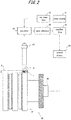
- Fig. 1 is a diagram illustrating a flow of a manufacturing process of a filter attached to a cigarette on a capsule filter making machine 10, a manufacturing process of the cigarette on a cigarette making machine 15, and an inspection process of a liquid-filled capsule (hereinafter, simply referred to as a "capsule") disposed inside the filter, the inspection process being performed on the cigarette making machine 15.
- a capsule liquid-filled capsule
- a capsule is supplied to be inserted into a filter material that is a bundle of acetate fibers supplied by a filter material supply process 11, by a capsule supply process 12, and thereafter the filter material with the capsule inserted therein is wound in a rod shape with wrapping paper in a winding process 13. Thereafter, in a cutting process 14, the filter rod is cut for each predetermined length with a cutter (not illustrated), so that a capsule filter rod is obtained.
- the manufactured capsule filter rod is sent to a filter tip attachment 16 in the cigarette making machine 15.
- the capsule filter rod is first integrally wound around a cigarette rod manufactured in a previous process through tipping paper, in a tip winding process 17.
- the capsule filter rod has a double length, and the cigarette rod is disposed on both end sides of the capsule filter rod with a double length on the drum, and the tipping paper is wound, so that a double cigarette is manufactured.
- This double cigarette is sent to a cutting process 18 performed on another drum, and is cut on this drum, so that cigarettes each having a length equal to one cigarette are manufactured.
- the manufactured cigarettes are sent to an inspection process 19, effective inspection related to the capsule is performed for the filter of each cigarette on machine by a capsule inspection apparatus illustrated in Fig. 2 , provided in the filter tip attachment 16.
- the capsule inspection apparatus is equivalent to an inspection apparatus according to the present invention.
- the capsule inspection apparatus has a control device 20 for performing various processes performed by the inspection apparatus, a probe antenna 23 for inspection related to quality of a placement state of a capsule 1a in a filter 1 of a cigarette 2, and a drum 30 that enables a conveyance of a plurality of the cigarettes 2 having the filters that become objects to be inspected.
- a circulator 24 is connected to the probe antenna 23, and an inspection electromagnetic wave supplied from a noise source 21 passes through a low pass filter 22, so that an inspection electromagnetic wave in a predetermined frequency band is generated in the circulator 24. Then, the inspection electromagnetic wave is input to the circulator 24.
- an electromagnetic wave having an oscillation frequency of 22 GHz to 40 GHz generated in the noise source 21 passes through the low pass filter 22, and an inspection electromagnetic wave having 20 GHz to 30 GHz is generated.
- the frequency of the inspection electromagnetic wave input to the circulator 24 may belong to 10 GHz to 100 GHz.
- a wave detector 25 is connected to an output unit of the circulator 24. This wave detector 25 extracts an electric reflected signal corresponding to a reflected electromagnetic wave described below. Thereafter, a predetermined electric process such as amplification and filtering is performed for the reflected signal by the amplifier filter 26, and the reflected signal is delivered to the control device 20.
- the probe antenna 23 has an oblong antenna case, and is disposed such that a tip of the probe antenna faces the filter 1 that is an object to be inspected. Then, the inspection electromagnetic wave is emitted from the tip. The emitted inspection electromagnetic wave is reflected by the filter 1 or a drum body 31 as described below, and the probe antenna 23 receives the reflected electromagnetic wave again. Therefore, in the capsule inspection apparatus illustrated in Fig. 2 , both the inspection electromagnetic wave and the reflected electromagnetic wave are conveyed inside the probe antenna 23. Therefore, a transmitting part of the inspection electromagnetic wave and a receiving part of the reflected electromagnetic wave are disposed on the same side with respect to the filter 1.
- the transmitting part of the inspection electromagnetic wave and the receiving part of the reflected electromagnetic wave of the probe antenna 23 are installed at such a position as to face the drum 30 that rotationally drives.
- a rotary encoder 32 is connected to the rotatably supported drum body 31 through a shaft.
- the cigarette 2 having the filter 1 as the object to be inspected is disposed on the drum body 31 of the drum 30 as illustrated in Fig. 2 .
- the drum body 31 is a cylindrical object made of metal
- a storage unit formed so as to axially store the cigarette 2 is disposed along the axial direction on a surface of the cylindrical object
- the cigarette 2 is stored inside the storage unit on the drum body 31 in a state where the filter 1 is located on a right end face side of the drum body 31 in Fig. 2
- a tobacco rod is located on a left end face side of the drum body 31 in Fig. 2 .
- the placement of the cigarette 2 illustrated in Fig. 2 is a state where the one cigarette 2 stored in the storage unit is projected on a sectional surface including a shaft of the cylindrical object.
- a plurality of the cigarettes 2 are rotationally conveyed while being stored on the surface of the cylindrical object of the drum body 31 at the same time.
- the filters 1 of the cigarettes 2 being rotationally conveyed on the drum body 31 are disposed on the surface of the cylindrical object of the drum body 31, and therefore in a part of the rotational conveyance process, as described above, such a positional relation that the transmitting part of the inspection electromagnetic wave of the probe antenna 23, and the receiving part of the reflected electromagnetic wave are capable of facing, namely, a positional relation that belongs to an inspection region in which the probe antenna 23 can emit the inspection electromagnetic wave, and receive the reflected electromagnetic wave is formed between the probe antenna 23 and the filter 1.
- the respective filters 1 of the plurality of cigarettes 2 are sequentially subjected to the inspection process by irradiation of the inspection electromagnetic wave from the probe antenna 23 by the capsule inspection apparatus illustrated in Fig. 2 .
- the rotary encoder 32 is driven by a drum driving shaft, and a pulse signal obtained from the rotary encoder 32 and a drum clock pulse (DCP) corresponding to each cigarette generated from the making machine are delivered to the control device 20 of the capsule inspection apparatus. Therefore, on the basis of the pulse signal and the DCP, the capsule inspection apparatus can grasp whether the inspection process is performed for the filters 1 of any of the cigarettes on the drum 30.
- DCP drum clock pulse
- a placement state of the capsule 1a inside the filter 1 by the capsule inspection apparatus will be described in detail.
- a state where the capsule 1a is normally disposed inside the filter 1 without being damaged, that is, without leaking flavoring liquid therein (hereinafter referred to as a "normal placement state")
- a state where the capsule 1a is damaged, and the flavoring liquid therein is leaked (hereinafter referred to as an "abnormal placement state")
- an “abnormal placement state” a state where the capsule 1a is damaged, and the flavoring liquid therein is leaked
- each of (a) to (c) illustrates a transition of the reception intensity of a reflected electromagnetic wave with respect to a conveyance distance in the width direction (in the direction perpendicular to a plane of Fig. 3 ) when the filter 1 is conveyed in the width direction with respect to the probe antenna 23 by the drum 30 in a state where the inspection electromagnetic wave is emitted.
- a line L1 denotes a reception intensity transition in a case where the placement state of the capsule 1a in the filter 1 is the normal placement state
- the line L2 denotes a reception intensity transition in a case where the placement state of the capsule 1a in the filter 1 is the abnormal placement state.
- the upper stage (a) of Fig. 3 corresponds to the storage state of the cigarette 2 which is a state where an end face of the filter 1 of the cigarette 2 (right end face in Fig. 3 ) is flush with a right end face of the drum body 31, that is, a state where a protrusion amount ⁇ L1 of the right end face of the filter 1 from the right end face of the drum body 31 is zero.
- a metal side face 31a of the drum body 31 is located on a side, opposite to the probe antenna 23, of the capsule 1a inside the filter 1.
- FIG. 3 illustrates the storage state of the cigarette 2 where the right end face of the filter 1 protrudes from the right end face of the drum body 31, and the protrusion amount is ⁇ L2.
- the metal side face 31a of the drum body 31 is still located on the side, opposite to the probe antenna 23, of the capsule 1a inside the filter 1.
- the lower stage (c) of Fig. 3 illustrates the storage state of the cigarette 2 where the right end face of the filter 1 protrudes from the right end face of the drum body 31, and the protrusion amount is ⁇ L3.
- the filter 1 protrudes from the right end face of the drum body 31, and the metal side face 31a of the drum body 31 is not located on the side, opposite to the probe antenna 23, of the capsule 1a inside the filter 1.
- the filter 1 is irradiated with an inspection electromagnetic wave emitted from an irradiation unit 23b so as to have fixed spread, and therefore the filter 1 in each of the storage states of (a) to (c) of Fig. 3 is located in a region where the inspection electromagnetic wave from the irradiation unit 23b is emitted.
- a part of the emitted inspection electromagnetic wave becomes a reflected electromagnetic wave that is reflected on the filter 1 side to go toward the probe antenna 23.
- the reflected electromagnetic wave includes electromagnetic waves reflected on various parts on the filter 1 side, and roughly the following four reflected electromagnetic waves can be cited as examples of forms.
- the inspection electromagnetic wave substantially does not act on the capsule 1a, and therefore information related to the placement state of the capsule 1a is not reflected in each of the reflected electromagnetic waves (1) and (3).
- the inspection electromagnetic wave (2) the inspection electromagnetic wave is reflected by the capsule 1a to be filled with the flavoring liquid, and therefore a part of the inspection electromagnetic wave is absorbed or the like at the time of this reflection. As a result, existence of the flavoring liquid inside the capsule 1a is reflected in the reception intensity of the reflected electromagnetic wave.
- the reflected electromagnetic wave (4) reflection of the electromagnetic wave is performed by the metal side face 31a, and the inspection electromagnetic wave is transmitted through the capsule 1a during the process of this reflection, and therefore a part of the inspection electromagnetic wave is absorbed or the like. As a result, existence of the flavoring liquid inside the capsule 1a is reflected in the reception intensity of the reflected electromagnetic wave similarly to the reflected electromagnetic wave (2).
- the capsule inspection apparatus performs an inspection process as to the quality of the placement state of the capsule 1a in the filter 1, that is, as to the normal placement state or the abnormal placement state, by utilizing the reflection of the existence of the flavoring liquid inside the capsule 1a to the reception intensity of this reflected electromagnetic wave. More specifically, in the storage state illustrated in Fig. 3(a) , the metal side face 31a exists on a back face of the capsule 1a as viewed from the probe antenna 23, and therefore the above reflected electromagnetic waves (2) and (4) can be received by the probe antenna 23.
- the capsule 1a When the capsule 1a is in the normal placement state, the flavoring liquid collectively exists in a fixed region inside the filter 1, and therefore the absorption degree of the inspection electromagnetic wave becomes large, and the reception intensity by the probe antenna 23 is largely lowered.
- the capsule 1a is disposed at almost the center in the width of the filter 1, and therefore it can be understood from Fig. 3(a) that when the capsule 1a is in the normal placement state, a transition in which the reception intensity is largely lowered at almost a median value of a conveyance distance is illustrated.
- the capsule 1a when the capsule 1a is in the abnormal placement state, the flavoring liquid is diffused into the filter 1, and therefore the absorption degree of the inspection electromagnetic wave becomes small, and the lowering amount of the reception intensity in the reception intensity transition become small compared to the case of the normal placement state.
- the lowering amount of the reception intensity in the reception intensity transition in the normal placement state is compared with the lowering amount of the reception intensity in the reception intensity transition in the abnormal placement state, a clear difference ⁇ V1 can be found as illustrated in Fig. 3(a) . Therefore, it is possible to separately determine the normal placement state and the abnormal placement state by utilizing the difference ⁇ V1 in the lowering amount of the reception intensity.
- a difference ⁇ V3 between the lowering amount of the reception intensity in the reception intensity transition in the normal placement state and the lowering amount of the reception intensity in the reception intensity transition in the abnormal placement state is smaller than the difference in the above state illustrated each of Figs. 3(a), and 3(b) , but it is possible to grasp the difference as the clear lowering amount of the reception intensity to some extent. Therefore, even in such a storage state, it is possible to separately determine the normal placement state and the abnormal placement state by utilizing the difference ⁇ V3.
- an inspection electromagnetic wave in 22 GHz to 28 GHz is emitted.
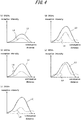
- an electromagnetic wave with a frequency, at which the difference in the lowering amount of the reception intensity between the normal placement state and the abnormal placement state is the largest, in a frequency band of 22 GHz to 28 GHz is preferably utilized. Therefore, in order to understand a correlation of the frequency of the inspection electromagnetic wave and the reception intensity, transition of the reception intensity of the reflected electromagnetic wave by the probe antenna 23 when the inspection electromagnetic wave with each frequency is utilized is illustrated in Fig. 4 . More specifically, Figs.
- 4(a) to 4(e) correspond to respective inspection electromagnetic waves with frequencies of 22 GHz, 24 GHz, 26 GHz, 28 GHz and 30 GHz, respectively, and a line L3 denotes a reception intensity transition in a case where the placement state of the capsule 1a in the filter 1 is the normal placement state, and a line L4 denotes a reception intensity transition in a case where the placement state of the capsule 1a in the filter 1 is the abnormal placement state.
- a reference numeral of the reception intensity of each reception intensity transition illustrated in Fig. 4 is reverse to a reference numeral of the reception intensity of each reception intensity transition illustrated in Fig. 3 .
- the difference in the change amount of the reception intensity between the normal placement state and the abnormal placement state is relatively largely expressed in any frequency in a frequency band of 22 GHz to 28 GHz, and therefore it can be said that the inspection electromagnetic wave having the frequency can be suitably utilized in the inspection process related to the placement state of the capsule 1a.
- the frequency of the inspection electromagnetic wave is 24 GHz or 26 GHz, it is found that this difference is the largest, and therefore the inspection process related to the placement state of the capsule 1a is most preferably performed by utilizing the inspection electromagnetic wave with 24 GHz or 26 GHz.
- the frequency of suitable inspection electromagnetic wave for this inspection process is changed depending on the shape, the size of the capsule 1a or the filter 1, components of the flavoring liquid inside the capsule 1a, the material of the filter 1, or the like, and therefore the frequency of the inspection electromagnetic wave may be appropriately set considering these factors.
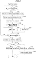
- the inspection process of the filter 1 performed by the capsule inspection apparatus of the present invention that is, the inspection process related to the placement state of the capsule 1a inside the filter 1 by utilizing the above inspection electromagnetic wave will be described in detail.
- a predetermined control program is performed in the control device 20.
- the inspection process is a process performed for the filter 1 provided in the single cigarette 2. Therefore, in a case where cigarettes are sequentially sent into the capsule inspection apparatus by the drum 30 as described above, the inspection process is repeatedly performed for the filter 1 of each cigarette 2.
- the inspection process of this embodiment is performed when the storage state of the cigarette 2 with respect to the drum body 31 is the storage state illustrated in Fig. 3(a) .
- the control device 20 can grasp a relative position of the cigarette to the inspection region by utilizing a pulse signal and the like from the rotary encoder 32, and therefore can determine that the filter 1 of the cigarette 2 conveyed by the drum 30 reaches the inside of the inspection region.
- positive determination is performed in S101
- the process advances to S102.
- negative determination is performed, the process of S101 is repeatedly performed, and reaching of the filter 1 to the inspection region is waited.
- the filter 1 that reaches the inspection region is irradiated with an inspection electromagnetic wave from the probe antenna 23.
- the process advances to S103.
- a reflected electromagnetic wave is received by the probe antenna 23.
- the storage state of the cigarette 2 with respect to the drum body 31 is the storage state illustrated in Fig. 3(a) , and therefore the reflected electromagnetic wave received by the probe antenna 23 includes all the above reflected electromagnetic waves (1) to (4).
- the process of S103 is terminated, the process advances to S104.
- the reception intensity of the reflected electromagnetic wave received in S103 is corrected. More specifically, the control device 20 previously has reception intensity by the probe antenna 23 when a non-disposed filter that is a reference filter and does not have the capsule 1a disposed therein is irradiated with the inspection electromagnetic wave from the probe antenna 23, as a reference signal intensity. Then, it can be said that reception intensity obtained by deducting the reference signal intensity from the reception intensity of the reflected electromagnetic wave received in S103 (hereinafter referred to as "corrected reception intensity”) is logically reception intensity reflecting only the placement state of the capsule 1a. Therefore, accuracy of the inspection process related to the placement state of the capsule 1a can be improved by utilizing the corrected reception intensity.
- the process of S104 is terminated, the process advances to S105.
- S105 it is determined whether or not the corrected reception intensity acquired in S104 is updated, that is, whether or not corrected reception intensity having lower intensity is acquired.
- first inspection electromagnetic wave irradiation is performed after the filter 1 reaches the inside of the inspection region, no corrected reception intensity acquired in the past exists, and therefore positive determination is performed in S105 in this case.
- second and subsequent inspection electromagnetic wave irradiation is performed, corrected reception intensity acquired in the past inspection electromagnetic wave irradiation (corrected reception intensity stored in a memory of the control device 20) is compared with corrected reception intensity acquired in inspection electromagnetic wave irradiation of this time.
- the reason why the data of the corrected reception intensity is updated is because in a case where the inspection electromagnetic wave is reflected on the surface of the capsule 1a, the reflected electromagnetic wave is received, the inspection electromagnetic wave transmitted through the capsule 1a is reflected on the metal side face 31a, and the reflected electromagnetic wave is transmitted through the capsule 1a again and thereafter received, that is, in a case where the probe antenna 23 receives the above reflected electromagnetic waves (2) and (4), it is considered the placement state of the capsule 1a is most effectively reflected in the reflected electromagnetic wave, and the corrected reception intensity or the reception intensity of the reflected electromagnetic wave at this time becomes the smallest.
- the process of S106 or S107 is terminated, the process advances to S108.
- S108 it is determined whether or not the filter 1 leaves the inspection region.
- the cigarette is rotationally conveyed by the drum 30. Therefore, the relative position of the cigarette to the inspection region at this point is grasped by utilizing the pulse signal and the like from the rotary encoder 32, and the determination process in S108 is performed.
- positive determination is performed in S108
- the process advances to S109.
- negative determination is performed, the process of S102 and the subsequent processes are repeatedly performed, and the acquiring process of corrected reception intensity by inspection electromagnetic wave irradiation to the filter 1 is performed again.
- the corrected reception intensity stored in the memory of the control device 20 is finally determined as peak reception intensity Vp.
- the peak reception intensity Vp is reception intensity which most intensely reflects the placement state of the capsule 1a disposed inside the filter 1 as an object to be inspected.
- the process advances to S110.
- determination related to the placement state of the capsule in the filter 1 as the object to be inspected is performed on the basis of the peak reception intensity Vp. More specifically, when the peak reception intensity Vp is smaller than a predetermined threshold value Rv, it is determined that the capsule 1a is in the normal placement state inside the filter 1 (process of S111).
- the peak reception intensity Vp is not smaller than the predetermined threshold value Rv
- it is determined that the capsule 1a is in the abnormal placement state inside the filter 1 (process of S112).
- the flavoring liquid is diffused in the filter 1. Therefore, an absorption effect of the flavoring liquid is unlikely to be reflected in the reflected electromagnetic wave, and the peak reception intensity Vp becomes a relatively large value.
- the determination of S110 is performed considering this point.
- the cigarette 2 having the filter 1 for which abnormal determination is performed in S112 is excluded from the drum 30 in S113.
- a known device for exclusion (for example, a device that excludes by using compressed air) is used.
- a device that excludes by using compressed air is used.
- the cigarette for which abnormal determination is performed is excluded, so that it is possible to avoid the cigarette from being packaged to be put on the market.
- inspection related to the placement state of the capsule 1a inside the filter 1 utilizing the reflected electromagnetic wave from the filter 1 side is performed by using the probe antenna 23 that transmits the inspection electromagnetic wave and receives the reflected electromagnetic wave.
- reflection type inspection it is possible to reduce space volume necessary for inspection as small as possible compared to a case where transmission type inspection of conventional technology is performed, and therefore it is possible to facilitate miniaturization of the capsule inspection apparatus.
- the inspection electromagnetic wave and the reflected electromagnetic wave are conveyed.
- the inspection electromagnetic wave and the reflected electromagnetic wave passes almost the same route in an inspection space between the probe antenna 23 and the filter 1. Therefore, in a case where the inspection electromagnetic wave is transmitted through the filter 1, and is received as the reflected electromagnetic wave by the probe antenna 23, the inspection electromagnetic wave passes through the same part of the filter 1, and therefore if the inspection electromagnetic wave is transmitted through the capsule 1a, the state of the capsule 1a can be intensely reflected in the reflected electromagnetic wave, and accuracy improvement of the inspection apparatus is expected.
- the inspection related to the placement state of the capsule 1a inside the filter 1 is performed on the basis of the reception intensity of the reflected electromagnetic wave.
- the inspection may be performed on the basis of phase shift of a reflected electromagnetic wave.
- This phase shift means phase shift between an inspection electromagnetic wave and a reflected electromagnetic wave.
- Fig. 6 illustrates a transition of phase shift when an inspection electromagnetic wave with each frequency is utilized. More specifically, Figs.
- 6(a) to 6(e) correspond to respective inspection electromagnetic waves with frequencies of 22 GHz, 24 GHz, 26 GHz, 28 GHz and 30 GHz, respectively, and a line L5 denotes a phase shift transition in a case where the placement state of a capsule 1a in a filter 1 is a normal placement state, and a line L6 denotes a phase shift transition in a case where the placement state of the capsule 1a in the filter 1 is an abnormal placement state.
- the inspection process related to the placement state of the capsule 1a based on the phase shift is preferably performed by utilizing the inspection electromagnetic wave with 26 GHz or 28 GHz. It is considered that the frequency of suitable inspection electromagnetic wave for this inspection process is changed depending on the shape, the size of the capsule 1a or the filter 1, components of flavoring liquid inside the capsule 1a, the material of the filter 1, or the like, and therefore the frequency of the inspection electromagnetic wave may be appropriately set considering these factors.
Landscapes
- Health & Medical Sciences (AREA)
- General Health & Medical Sciences (AREA)
- Toxicology (AREA)
- Manufacturing Of Cigar And Cigarette Tobacco (AREA)
- Investigating Or Analysing Materials By Optical Means (AREA)
- Cigarettes, Filters, And Manufacturing Of Filters (AREA)
Claims (8)
- Filterinspektionseinrichtung zum Inspizieren von Qualität bezüglich eines Platzierungszustands eines vorgegebenen anzuordnenden Objekts, das innerhalb eines Filters für einen Rauchartikel (2) anzuordnen ist, wobei die Filterinspektionseinrichtung umfasst:eine Bestrahlungseinheit (23b), die ein Zielfilter (1) mit einer elektromagnetischen Inspektionswelle bestrahlt, die eine vorgegebene Frequenz aufweist, wobei das Zielfilter (1) das Filter für einen Rauchartikel (2) als ein zu inspizierendes Ziel ist;eine Empfangseinheit, die eine reflektierte elektromagnetische Welle von dem Zielfilter (1) empfängt, die von der elektromagnetischen Inspektionswelle resultiert, die von der Bestrahlungseinheit (23b) emittiert wird;eine Antenneneinheit (23), die angeordnet ist, zu dem Zielfilter (1) zu zeigen und die elektromagnetische Inspektionswelle und die reflektierte elektromagnetische Welle ausbreitet;eine Beschaffungseinheit, die auf der Basis eines reflektierten Signals, das von der Empfangseinheit erhalten wird, vorgegebene Informationen bezüglich Intensität des reflektierten Signals oder Phasenverschiebung des reflektierten Signals, die mit dem Platzierungszustand des vorgegebenen Objekts verknüpft ist, das innerhalb des Zielfilters (1) anzuordnen ist, beschafft;eine Bestimmungseinheit, die die Qualität des Platzierungszustands des vorgegebenen anzuordnenden Objekts, das in dem Zielfilter (1) angeordnet ist, auf der Basis der vorgegebenen Informationen, die von der Beschaffungseinheit beschafft wurden, bestimmt; undeine Reflexionseinheit, die an einem hinteren Teil des Zielfilters (1) angeordnet ist, wobei das hintere Teil an einer Seite gegenüber der Antenneneinheit (23) liegt und gebildet ist, eine elektromagnetische Übertragungswelle an einer Seite des Zielfilters wieder zu reflektieren, wobei die elektromagnetische Übertragungswelle ein Teil der emittierten elektromagnetischen Inspektionswelle ist und durch das Zielfilter (1) übertragen wird, wobeidie Empfangseinheit eine sekundäre reflektierte elektromagnetische Welle, die eine elektromagnetische Welle ist, die erhalten wird, indem die elektromagnetische Übertragungswelle von der Reflexionseinheit reflektiert wird, zusätzlich zu der reflektierten elektromagnetischen Welle von dem Zielfilter (1) empfängt.
- Filterinspektionseinrichtung nach Anspruch 1, wobei
die Antenneneinheit (23) gebildet ist, um in demselben Antennengehäuse die elektromagnetische Inspektionswelle an das Zielfilter (1) zu übertragen und die reflektierte elektromagnetische Welle von dem Zielfilter (1) zu empfangen. - Filterinspektionseinrichtung nach Anspruch 1 oder 2, wobei
die vorgegebene Frequenz eine Frequenz ist, die zu einem Bereich von 10 GHz bis 100 Ghz gehört. - Filterinspektionseinrichtung nach Anspruch 1 oder Anspruch 2, wobei
die vorgegebene Frequenz eine Frequenz ist, die zu einem Bereich von 20 GHz bis 30 GHz gehört. - Filterinspektionseinrichtung nach Anspruch 1, weiter umfassend
eine Beförderungsvorrichtung (30), die eine Vielzahl der Filter für Rauchartikel (2) in einem Zustand befördert, wo die Filter für Rauchartikel (2) auf einem Beförderungsgestell platziert sind, und die derart in Bezug auf die Antenneneinheit (23) angeordnet ist, dass das Zielfilter (1), das in dem Filter für einen Rauchartikel (2) beinhaltet ist, der von der Beförderungsvorrichtung (30) befördert wird, mit der elektromagnetischen Inspektionswelle bestrahlt wird, wobei
die Reflexionseinheit ein vorgegebenes Bauteil (31) ist, das in dem Beförderungsgestell beinhaltet ist und aus Metall hergestellt ist. - Filterinspektionseinrichtung nach einem der Ansprüche 1 bis Anspruch 5, wobei
die vorgegebenen Informationen Informationen bezüglich Intensität des reflektierten Signals sind,
die Filterinspektionseinrichtung weiter umfasst
eine Korrektureinheit, die die vorgegebenen Informationen, die von der Beschaffungseinheit beschafft werden, auf der Basis von Informationen bezüglich einer Referenzsignalintensität korrigiert, die zuvor durch Bestrahlen eines Referenzfilters mit der elektromagnetischen Inspektionswelle, die die vorgegebene Frequenz aufweist, erhalten wurden, wobei das Referenzfilter ein Filter für einen Rauchartikel (2) ist, in dem das vorgegebene anzuordnende Objekt nicht angeordnet ist, wobei
die Bestimmungseinheit die Qualität des Platzierungszustands des vorgegebenen anzuordnenden Objekts, das in dem Zielfilter (1) angeordnet ist, auf der Basis der vorgegebenen Informationen, die von der Korrektureinheit korrigiert werden, bestimmt. - Filterinspektionseinrichtung nach einem der Ansprüche 1 bis Anspruch 6, wobei
das beförderte Zielfilter (1) mit der elektromagnetischen Inspektionswelle von der Bestrahlungseinheit (23b) bestrahlt wird, und
während das Zielfilter (1) durch einen vorgegebenen Bestrahlungsbereich durchgeht, der eingestellt ist, Bestrahlung der elektromagnetischen Inspektionswelle durch die Bestrahlungseinheit und Empfang der reflektierten elektromagnetischen Welle durch die Empfangseinheit zu ermöglichen, die Beschaffungseinheit Informationen bezüglich Intensität des reflektierten Signals oder Informationen bezüglich Phasenverschiebung des reflektierten Signals eine Vielzahl von Malen beschafft und Intensitätsinformationen, in denen Änderung in Bezug auf die elektromagnetische Inspektionswelle maximal ist, oder Phasenverschiebungsinformationen, in denen Änderung in Bezug auf die elektromagnetische Inspektionswelle maximal ist, als die vorgegebenen Informationen unter den beschafften Intensitätsinformationen oder den beschafften Phasenverschiebungsinformationen beschafft. - Filterinspektionseinrichtung nach einem der Ansprüche 1 bis Anspruch 7, wobei
das vorgegebene anzuordnende Objekt eine flüssigkeitsgefüllte Kapsel (1a) ist, die mit einer vorgegebenen Aromaflüssigkeit gefüllt ist.
Priority Applications (1)
| Application Number | Priority Date | Filing Date | Title |
|---|---|---|---|
| PL14909081T PL3238552T3 (pl) | 2014-12-26 | 2014-12-26 | Urządzenie do kontroli filtra |
Applications Claiming Priority (1)
| Application Number | Priority Date | Filing Date | Title |
|---|---|---|---|
| PCT/JP2014/084599 WO2016103477A1 (ja) | 2014-12-26 | 2014-12-26 | フィルタ検査装置 |
Publications (4)
| Publication Number | Publication Date |
|---|---|
| EP3238552A1 EP3238552A1 (de) | 2017-11-01 |
| EP3238552A4 EP3238552A4 (de) | 2018-08-08 |
| EP3238552B1 true EP3238552B1 (de) | 2021-07-14 |
| EP3238552B8 EP3238552B8 (de) | 2021-10-27 |
Family
ID=56149562
Family Applications (1)
| Application Number | Title | Priority Date | Filing Date |
|---|---|---|---|
| EP14909081.3A Active EP3238552B8 (de) | 2014-12-26 | 2014-12-26 | Filterprüfungsvorrichtung |
Country Status (4)
| Country | Link |
|---|---|
| EP (1) | EP3238552B8 (de) |
| JP (1) | JP6367369B2 (de) |
| PL (1) | PL3238552T3 (de) |
| WO (1) | WO2016103477A1 (de) |
Families Citing this family (4)
| Publication number | Priority date | Publication date | Assignee | Title |
|---|---|---|---|---|
| CN109580533A (zh) * | 2018-11-30 | 2019-04-05 | 深圳市太赫兹科技创新研究院有限公司 | 香烟滤嘴监测方法和系统 |
| CN113766838B (zh) * | 2019-08-20 | 2023-07-07 | 日本烟草产业株式会社 | 圆筒状加热型吸烟物品的制造方法以及制造装置 |
| CN110496794B (zh) * | 2019-08-28 | 2021-06-29 | 贵州大学 | 一种爆珠香烟过滤嘴中爆珠质量检测控制系统及其控制方法 |
| CN110604337B (zh) * | 2019-10-17 | 2021-07-13 | 浙江中烟工业有限责任公司 | 一种卷烟爆珠的检测装置及检测方法 |
Family Cites Families (13)
| Publication number | Priority date | Publication date | Assignee | Title |
|---|---|---|---|---|
| JPS59131375A (ja) * | 1983-01-17 | 1984-07-28 | 住友ゴム工業株式会社 | ゴルフボール選別方法及び選別装置 |
| JPH041437U (de) * | 1990-04-17 | 1992-01-08 | ||
| WO2002097411A1 (en) * | 2001-05-31 | 2002-12-05 | Orbylgjutaekni Ehf. | Apparatus and method for microwave determination of at least one physical parameter of a substance |
| ITBO20020038A1 (it) * | 2002-01-24 | 2003-07-24 | Gd Spa | Metodo per il rilevamento e l'eliminazione di corpi estranei in un flusso di tabacco |
| JP4731130B2 (ja) * | 2004-06-09 | 2011-07-20 | 株式会社パル技研 | 異物検査方法 |
| JP2006090802A (ja) * | 2004-09-22 | 2006-04-06 | Jt Engineering Inc | 欠陥検査装置 |
| JP2008131856A (ja) * | 2005-02-28 | 2008-06-12 | Japan Tobacco Inc | 多重フィルタロッドの検査装置 |
| US8186359B2 (en) * | 2008-02-01 | 2012-05-29 | R. J. Reynolds Tobacco Company | System for analyzing a filter element associated with a smoking article, and associated method |
| JP2012063324A (ja) * | 2010-09-17 | 2012-03-29 | Kanazawa Univ | 異物検出システム、異物センサ及び検出装置 |
| JP2014178117A (ja) * | 2011-07-06 | 2014-09-25 | Japan Tobacco Inc | カプセル検査装置及びその検査方法 |
| WO2013145163A1 (ja) * | 2012-03-28 | 2013-10-03 | 日本たばこ産業株式会社 | シガレットのフィルタ検査装置及びその検査方法 |
| US9664570B2 (en) * | 2012-11-13 | 2017-05-30 | R.J. Reynolds Tobacco Company | System for analyzing a smoking article filter associated with a smoking article, and associated method |
| DE102013201512A1 (de) * | 2013-01-30 | 2014-08-14 | Hauni Maschinenbau Ag | Messvorrichtung, Maschine und Verfahren der Tabak verarbeitenden Industrie |
-
2014
- 2014-12-26 WO PCT/JP2014/084599 patent/WO2016103477A1/ja not_active Ceased
- 2014-12-26 EP EP14909081.3A patent/EP3238552B8/de active Active
- 2014-12-26 PL PL14909081T patent/PL3238552T3/pl unknown
- 2014-12-26 JP JP2016565821A patent/JP6367369B2/ja active Active
Non-Patent Citations (1)
| Title |
|---|
| None * |
Also Published As
| Publication number | Publication date |
|---|---|
| JP6367369B2 (ja) | 2018-08-01 |
| EP3238552A1 (de) | 2017-11-01 |
| EP3238552A4 (de) | 2018-08-08 |
| EP3238552B8 (de) | 2021-10-27 |
| WO2016103477A1 (ja) | 2016-06-30 |
| PL3238552T3 (pl) | 2021-12-06 |
| JPWO2016103477A1 (ja) | 2017-05-25 |
Similar Documents
| Publication | Publication Date | Title |
|---|---|---|
| EP3238552B1 (de) | Filterprüfungsvorrichtung | |
| CN106455678B (zh) | 微波测量装置、用于检验烟草加工业的棒形制品或材料条的组件和方法及烟草加工业的机器 | |
| US7176696B2 (en) | Method of detecting and eliminating foreign bodies in a flow of tobacco | |
| EP2848133B1 (de) | Anordnung und Verfahren zur Überprüfung von stabförmigen Artikeln der Tabak verarbeitenden Industrie | |
| US6768317B2 (en) | Method of and apparatus for testing a first material for potential presence of second materials | |
| CN104000304B (zh) | 用于检测物体位置的测量方法和测量系统以及机器 | |
| CA2647214C (fr) | Dispositif d'analyse de la composition du contenu d'un recipient ameliore | |
| CN105249529B (zh) | 烟草加工行业的机器、滚筒系统及棒形制品的检测方法 | |
| EP2762015B1 (de) | Anordnung und Verfahren zur Überprüfung von stabförmigen Artikeln der Tabak verarbeitenden Industrie | |
| US20180027868A1 (en) | Suction belt conveyor and rod-forming machine of the tobacco processing industry, and use and method for measuring material properties of a material rod of the tobacco processing industry | |
| US5596187A (en) | Optical method for examining the open end of a cigarette to determine its uniformity of filling with tobacco | |
| CN103504473B (zh) | 对烟草加工业的材料条的条异质性进行识别的方法和装置 | |
| JP6253908B2 (ja) | 繊維状材料で作製された長尺要素の検査方法 | |
| CN103960773A (zh) | 烟草加工工业的测量装置、机器和方法 | |
| EP2183985B1 (de) | Bestimmung der Fertigungslinie | |
| CN103635105A (zh) | 烟草加工业的机器的起动 | |
| US5406376A (en) | Apparatus for testing end portions of rod-shaped articles of the tobacco processing industry | |
| CN107692306A (zh) | 用于识别和/或检查插入到烟草加工行业的棒形或条形制品中的对象的方法和装置 | |
| US7027148B2 (en) | Method and apparatus for determining the triacetin content in filter plugs | |
| RU2684388C2 (ru) | Измерительное устройство и способ измерения для многосегментных стержнеобразных изделий табачной промышленности | |
| JP2013118856A (ja) | コンバイン | |
| JP2000014376A (ja) | シガレット用フィルタロッドの検査装置及びその検査方法 | |
| CN114828665B (zh) | 标记物检测以及剔除方法和设备 | |
| EP2745718A1 (de) | Banddetektionssensor und detektionsverfahren dafür | |
| ITBO20060585A1 (it) | Dispositivo per la rilevazione di una caratteristica di un materiale fibroso. |
Legal Events
| Date | Code | Title | Description |
|---|---|---|---|
| STAA | Information on the status of an ep patent application or granted ep patent |
Free format text: STATUS: THE INTERNATIONAL PUBLICATION HAS BEEN MADE |
|
| PUAI | Public reference made under article 153(3) epc to a published international application that has entered the european phase |
Free format text: ORIGINAL CODE: 0009012 |
|
| STAA | Information on the status of an ep patent application or granted ep patent |
Free format text: STATUS: REQUEST FOR EXAMINATION WAS MADE |
|
| 17P | Request for examination filed |
Effective date: 20170726 |
|
| AK | Designated contracting states |
Kind code of ref document: A1 Designated state(s): AL AT BE BG CH CY CZ DE DK EE ES FI FR GB GR HR HU IE IS IT LI LT LU LV MC MK MT NL NO PL PT RO RS SE SI SK SM TR |
|
| AX | Request for extension of the european patent |
Extension state: BA ME |
|
| DAX | Request for extension of the european patent (deleted) | ||
| REG | Reference to a national code |
Ref country code: DE Ref legal event code: R079 Ref document number: 602014078830 Country of ref document: DE Free format text: PREVIOUS MAIN CLASS: A24D0003000000 Ipc: A24C0005340000 |
|
| A4 | Supplementary search report drawn up and despatched |
Effective date: 20180706 |
|
| RIC1 | Information provided on ipc code assigned before grant |
Ipc: A24C 5/34 20060101AFI20180702BHEP Ipc: A24D 3/02 20060101ALI20180702BHEP |
|
| RAP1 | Party data changed (applicant data changed or rights of an application transferred) |
Owner name: JAPAN TOBACCO INC. |
|
| STAA | Information on the status of an ep patent application or granted ep patent |
Free format text: STATUS: EXAMINATION IS IN PROGRESS |
|
| 17Q | First examination report despatched |
Effective date: 20200305 |
|
| GRAP | Despatch of communication of intention to grant a patent |
Free format text: ORIGINAL CODE: EPIDOSNIGR1 |
|
| STAA | Information on the status of an ep patent application or granted ep patent |
Free format text: STATUS: GRANT OF PATENT IS INTENDED |
|
| RAP1 | Party data changed (applicant data changed or rights of an application transferred) |
Owner name: HAKKO AUTOMATION CO., LTD. Owner name: JAPAN TOBACCO INC. |
|
| INTG | Intention to grant announced |
Effective date: 20210126 |
|
| GRAS | Grant fee paid |
Free format text: ORIGINAL CODE: EPIDOSNIGR3 |
|
| GRAF | Information related to payment of grant fee modified |
Free format text: ORIGINAL CODE: EPIDOSCIGR3 |
|
| GRAA | (expected) grant |
Free format text: ORIGINAL CODE: 0009210 |
|
| STAA | Information on the status of an ep patent application or granted ep patent |
Free format text: STATUS: THE PATENT HAS BEEN GRANTED |
|
| AK | Designated contracting states |
Kind code of ref document: B1 Designated state(s): AL AT BE BG CH CY CZ DE DK EE ES FI FR GB GR HR HU IE IS IT LI LT LU LV MC MK MT NL NO PL PT RO RS SE SI SK SM TR |
|
| REG | Reference to a national code |
Ref country code: GB Ref legal event code: FG4D |
|
| REG | Reference to a national code |
Ref country code: DE Ref legal event code: R096 Ref document number: 602014078830 Country of ref document: DE |
|
| REG | Reference to a national code |
Ref country code: IE Ref legal event code: FG4D |
|
| REG | Reference to a national code |
Ref country code: AT Ref legal event code: REF Ref document number: 1409954 Country of ref document: AT Kind code of ref document: T Effective date: 20210815 |
|
| GRAT | Correction requested after decision to grant or after decision to maintain patent in amended form |
Free format text: ORIGINAL CODE: EPIDOSNCDEC |
|
| REG | Reference to a national code |
Ref country code: CH Ref legal event code: PK Free format text: BERICHTIGUNG B8 |
|
| RAP4 | Party data changed (patent owner data changed or rights of a patent transferred) |
Owner name: JAPAN TOBACCO INC. |
|
| REG | Reference to a national code |
Ref country code: LT Ref legal event code: MG9D |
|
| REG | Reference to a national code |
Ref country code: NL Ref legal event code: MP Effective date: 20210714 |
|
| REG | Reference to a national code |
Ref country code: AT Ref legal event code: MK05 Ref document number: 1409954 Country of ref document: AT Kind code of ref document: T Effective date: 20210714 |
|
| PG25 | Lapsed in a contracting state [announced via postgrant information from national office to epo] |
Ref country code: LT Free format text: LAPSE BECAUSE OF FAILURE TO SUBMIT A TRANSLATION OF THE DESCRIPTION OR TO PAY THE FEE WITHIN THE PRESCRIBED TIME-LIMIT Effective date: 20210714 Ref country code: AT Free format text: LAPSE BECAUSE OF FAILURE TO SUBMIT A TRANSLATION OF THE DESCRIPTION OR TO PAY THE FEE WITHIN THE PRESCRIBED TIME-LIMIT Effective date: 20210714 Ref country code: BG Free format text: LAPSE BECAUSE OF FAILURE TO SUBMIT A TRANSLATION OF THE DESCRIPTION OR TO PAY THE FEE WITHIN THE PRESCRIBED TIME-LIMIT Effective date: 20211014 Ref country code: ES Free format text: LAPSE BECAUSE OF FAILURE TO SUBMIT A TRANSLATION OF THE DESCRIPTION OR TO PAY THE FEE WITHIN THE PRESCRIBED TIME-LIMIT Effective date: 20210714 Ref country code: FI Free format text: LAPSE BECAUSE OF FAILURE TO SUBMIT A TRANSLATION OF THE DESCRIPTION OR TO PAY THE FEE WITHIN THE PRESCRIBED TIME-LIMIT Effective date: 20210714 Ref country code: NO Free format text: LAPSE BECAUSE OF FAILURE TO SUBMIT A TRANSLATION OF THE DESCRIPTION OR TO PAY THE FEE WITHIN THE PRESCRIBED TIME-LIMIT Effective date: 20211014 Ref country code: PT Free format text: LAPSE BECAUSE OF FAILURE TO SUBMIT A TRANSLATION OF THE DESCRIPTION OR TO PAY THE FEE WITHIN THE PRESCRIBED TIME-LIMIT Effective date: 20211115 Ref country code: NL Free format text: LAPSE BECAUSE OF FAILURE TO SUBMIT A TRANSLATION OF THE DESCRIPTION OR TO PAY THE FEE WITHIN THE PRESCRIBED TIME-LIMIT Effective date: 20210714 Ref country code: RS Free format text: LAPSE BECAUSE OF FAILURE TO SUBMIT A TRANSLATION OF THE DESCRIPTION OR TO PAY THE FEE WITHIN THE PRESCRIBED TIME-LIMIT Effective date: 20210714 Ref country code: SE Free format text: LAPSE BECAUSE OF FAILURE TO SUBMIT A TRANSLATION OF THE DESCRIPTION OR TO PAY THE FEE WITHIN THE PRESCRIBED TIME-LIMIT Effective date: 20210714 Ref country code: HR Free format text: LAPSE BECAUSE OF FAILURE TO SUBMIT A TRANSLATION OF THE DESCRIPTION OR TO PAY THE FEE WITHIN THE PRESCRIBED TIME-LIMIT Effective date: 20210714 |
|
| PG25 | Lapsed in a contracting state [announced via postgrant information from national office to epo] |
Ref country code: LV Free format text: LAPSE BECAUSE OF FAILURE TO SUBMIT A TRANSLATION OF THE DESCRIPTION OR TO PAY THE FEE WITHIN THE PRESCRIBED TIME-LIMIT Effective date: 20210714 Ref country code: GR Free format text: LAPSE BECAUSE OF FAILURE TO SUBMIT A TRANSLATION OF THE DESCRIPTION OR TO PAY THE FEE WITHIN THE PRESCRIBED TIME-LIMIT Effective date: 20211015 |
|
| REG | Reference to a national code |
Ref country code: DE Ref legal event code: R097 Ref document number: 602014078830 Country of ref document: DE |
|
| PG25 | Lapsed in a contracting state [announced via postgrant information from national office to epo] |
Ref country code: DK Free format text: LAPSE BECAUSE OF FAILURE TO SUBMIT A TRANSLATION OF THE DESCRIPTION OR TO PAY THE FEE WITHIN THE PRESCRIBED TIME-LIMIT Effective date: 20210714 |
|
| PLBE | No opposition filed within time limit |
Free format text: ORIGINAL CODE: 0009261 |
|
| STAA | Information on the status of an ep patent application or granted ep patent |
Free format text: STATUS: NO OPPOSITION FILED WITHIN TIME LIMIT |
|
| PG25 | Lapsed in a contracting state [announced via postgrant information from national office to epo] |
Ref country code: SM Free format text: LAPSE BECAUSE OF FAILURE TO SUBMIT A TRANSLATION OF THE DESCRIPTION OR TO PAY THE FEE WITHIN THE PRESCRIBED TIME-LIMIT Effective date: 20210714 Ref country code: SK Free format text: LAPSE BECAUSE OF FAILURE TO SUBMIT A TRANSLATION OF THE DESCRIPTION OR TO PAY THE FEE WITHIN THE PRESCRIBED TIME-LIMIT Effective date: 20210714 Ref country code: RO Free format text: LAPSE BECAUSE OF FAILURE TO SUBMIT A TRANSLATION OF THE DESCRIPTION OR TO PAY THE FEE WITHIN THE PRESCRIBED TIME-LIMIT Effective date: 20210714 Ref country code: EE Free format text: LAPSE BECAUSE OF FAILURE TO SUBMIT A TRANSLATION OF THE DESCRIPTION OR TO PAY THE FEE WITHIN THE PRESCRIBED TIME-LIMIT Effective date: 20210714 Ref country code: CZ Free format text: LAPSE BECAUSE OF FAILURE TO SUBMIT A TRANSLATION OF THE DESCRIPTION OR TO PAY THE FEE WITHIN THE PRESCRIBED TIME-LIMIT Effective date: 20210714 Ref country code: AL Free format text: LAPSE BECAUSE OF FAILURE TO SUBMIT A TRANSLATION OF THE DESCRIPTION OR TO PAY THE FEE WITHIN THE PRESCRIBED TIME-LIMIT Effective date: 20210714 |
|
| 26N | No opposition filed |
Effective date: 20220419 |
|
| PG25 | Lapsed in a contracting state [announced via postgrant information from national office to epo] |
Ref country code: MC Free format text: LAPSE BECAUSE OF FAILURE TO SUBMIT A TRANSLATION OF THE DESCRIPTION OR TO PAY THE FEE WITHIN THE PRESCRIBED TIME-LIMIT Effective date: 20210714 |
|
| REG | Reference to a national code |
Ref country code: CH Ref legal event code: PL |
|
| GBPC | Gb: european patent ceased through non-payment of renewal fee |
Effective date: 20211226 |
|
| REG | Reference to a national code |
Ref country code: BE Ref legal event code: MM Effective date: 20211231 |
|
| PG25 | Lapsed in a contracting state [announced via postgrant information from national office to epo] |
Ref country code: LU Free format text: LAPSE BECAUSE OF NON-PAYMENT OF DUE FEES Effective date: 20211226 Ref country code: IE Free format text: LAPSE BECAUSE OF NON-PAYMENT OF DUE FEES Effective date: 20211226 Ref country code: GB Free format text: LAPSE BECAUSE OF NON-PAYMENT OF DUE FEES Effective date: 20211226 |
|
| PG25 | Lapsed in a contracting state [announced via postgrant information from national office to epo] |
Ref country code: FR Free format text: LAPSE BECAUSE OF NON-PAYMENT OF DUE FEES Effective date: 20211231 Ref country code: BE Free format text: LAPSE BECAUSE OF NON-PAYMENT OF DUE FEES Effective date: 20211231 |
|
| PG25 | Lapsed in a contracting state [announced via postgrant information from national office to epo] |
Ref country code: LI Free format text: LAPSE BECAUSE OF NON-PAYMENT OF DUE FEES Effective date: 20211231 Ref country code: CH Free format text: LAPSE BECAUSE OF NON-PAYMENT OF DUE FEES Effective date: 20211231 |
|
| PG25 | Lapsed in a contracting state [announced via postgrant information from national office to epo] |
Ref country code: HU Free format text: LAPSE BECAUSE OF FAILURE TO SUBMIT A TRANSLATION OF THE DESCRIPTION OR TO PAY THE FEE WITHIN THE PRESCRIBED TIME-LIMIT; INVALID AB INITIO Effective date: 20141226 |
|
| PG25 | Lapsed in a contracting state [announced via postgrant information from national office to epo] |
Ref country code: CY Free format text: LAPSE BECAUSE OF FAILURE TO SUBMIT A TRANSLATION OF THE DESCRIPTION OR TO PAY THE FEE WITHIN THE PRESCRIBED TIME-LIMIT Effective date: 20210714 |
|
| P01 | Opt-out of the competence of the unified patent court (upc) registered |
Effective date: 20230530 |
|
| PG25 | Lapsed in a contracting state [announced via postgrant information from national office to epo] |
Ref country code: MK Free format text: LAPSE BECAUSE OF FAILURE TO SUBMIT A TRANSLATION OF THE DESCRIPTION OR TO PAY THE FEE WITHIN THE PRESCRIBED TIME-LIMIT Effective date: 20210714 |
|
| PG25 | Lapsed in a contracting state [announced via postgrant information from national office to epo] |
Ref country code: TR Free format text: LAPSE BECAUSE OF FAILURE TO SUBMIT A TRANSLATION OF THE DESCRIPTION OR TO PAY THE FEE WITHIN THE PRESCRIBED TIME-LIMIT Effective date: 20210714 |
|
| PG25 | Lapsed in a contracting state [announced via postgrant information from national office to epo] |
Ref country code: MT Free format text: LAPSE BECAUSE OF FAILURE TO SUBMIT A TRANSLATION OF THE DESCRIPTION OR TO PAY THE FEE WITHIN THE PRESCRIBED TIME-LIMIT Effective date: 20210714 |
|
| PGFP | Annual fee paid to national office [announced via postgrant information from national office to epo] |
Ref country code: PL Payment date: 20241213 Year of fee payment: 11 |
|
| PGFP | Annual fee paid to national office [announced via postgrant information from national office to epo] |
Ref country code: DE Payment date: 20251211 Year of fee payment: 12 |
|
| PGFP | Annual fee paid to national office [announced via postgrant information from national office to epo] |
Ref country code: IT Payment date: 20251223 Year of fee payment: 12 |