EP3238337B1 - Verfahren zum betreiben eines antriebsstranges - Google Patents
Verfahren zum betreiben eines antriebsstranges Download PDFInfo
- Publication number
- EP3238337B1 EP3238337B1 EP15825785.7A EP15825785A EP3238337B1 EP 3238337 B1 EP3238337 B1 EP 3238337B1 EP 15825785 A EP15825785 A EP 15825785A EP 3238337 B1 EP3238337 B1 EP 3238337B1
- Authority
- EP
- European Patent Office
- Prior art keywords
- drive
- differential
- speed
- machine
- frequency converter
- Prior art date
- Legal status (The legal status is an assumption and is not a legal conclusion. Google has not performed a legal analysis and makes no representation as to the accuracy of the status listed.)
- Active
Links
Images


Classifications
-
- H—ELECTRICITY
- H02—GENERATION; CONVERSION OR DISTRIBUTION OF ELECTRIC POWER
- H02P—CONTROL OR REGULATION OF ELECTRIC MOTORS, ELECTRIC GENERATORS OR DYNAMO-ELECTRIC CONVERTERS; CONTROLLING TRANSFORMERS, REACTORS OR CHOKE COILS
- H02P5/00—Arrangements specially adapted for regulating or controlling the speed or torque of two or more electric motors
- H02P5/74—Arrangements specially adapted for regulating or controlling the speed or torque of two or more electric motors controlling two or more AC dynamo-electric motors
- H02P5/747—Arrangements specially adapted for regulating or controlling the speed or torque of two or more electric motors controlling two or more AC dynamo-electric motors mechanically coupled by gearing
- H02P5/753—Differential gearing
-
- F—MECHANICAL ENGINEERING; LIGHTING; HEATING; WEAPONS; BLASTING
- F16—ENGINEERING ELEMENTS AND UNITS; GENERAL MEASURES FOR PRODUCING AND MAINTAINING EFFECTIVE FUNCTIONING OF MACHINES OR INSTALLATIONS; THERMAL INSULATION IN GENERAL
- F16H—GEARING
- F16H3/00—Toothed gearings for conveying rotary motion with variable gear ratio or for reversing rotary motion
- F16H3/44—Toothed gearings for conveying rotary motion with variable gear ratio or for reversing rotary motion using gears having orbital motion
- F16H3/72—Toothed gearings for conveying rotary motion with variable gear ratio or for reversing rotary motion using gears having orbital motion with a secondary drive, e.g. regulating motor, in order to vary speed continuously
- F16H3/724—Toothed gearings for conveying rotary motion with variable gear ratio or for reversing rotary motion using gears having orbital motion with a secondary drive, e.g. regulating motor, in order to vary speed continuously using externally powered electric machines
-
- H—ELECTRICITY
- H02—GENERATION; CONVERSION OR DISTRIBUTION OF ELECTRIC POWER
- H02P—CONTROL OR REGULATION OF ELECTRIC MOTORS, ELECTRIC GENERATORS OR DYNAMO-ELECTRIC CONVERTERS; CONTROLLING TRANSFORMERS, REACTORS OR CHOKE COILS
- H02P5/00—Arrangements specially adapted for regulating or controlling the speed or torque of two or more electric motors
- H02P5/74—Arrangements specially adapted for regulating or controlling the speed or torque of two or more electric motors controlling two or more AC dynamo-electric motors
- H02P5/747—Arrangements specially adapted for regulating or controlling the speed or torque of two or more electric motors controlling two or more AC dynamo-electric motors mechanically coupled by gearing
-
- F—MECHANICAL ENGINEERING; LIGHTING; HEATING; WEAPONS; BLASTING
- F04—POSITIVE - DISPLACEMENT MACHINES FOR LIQUIDS; PUMPS FOR LIQUIDS OR ELASTIC FLUIDS
- F04D—NON-POSITIVE-DISPLACEMENT PUMPS
- F04D27/00—Control, e.g. regulation, of pumps, pumping installations or pumping systems specially adapted for elastic fluids
-
- F—MECHANICAL ENGINEERING; LIGHTING; HEATING; WEAPONS; BLASTING
- F16—ENGINEERING ELEMENTS AND UNITS; GENERAL MEASURES FOR PRODUCING AND MAINTAINING EFFECTIVE FUNCTIONING OF MACHINES OR INSTALLATIONS; THERMAL INSULATION IN GENERAL
- F16H—GEARING
- F16H61/00—Control functions within control units of change-speed- or reversing-gearings for conveying rotary motion ; Control of exclusively fluid gearing, friction gearing, gearings with endless flexible members or other particular types of gearing
- F16H61/66—Control functions within control units of change-speed- or reversing-gearings for conveying rotary motion ; Control of exclusively fluid gearing, friction gearing, gearings with endless flexible members or other particular types of gearing specially adapted for continuously variable gearings
-
- H—ELECTRICITY
- H02—GENERATION; CONVERSION OR DISTRIBUTION OF ELECTRIC POWER
- H02P—CONTROL OR REGULATION OF ELECTRIC MOTORS, ELECTRIC GENERATORS OR DYNAMO-ELECTRIC CONVERTERS; CONTROLLING TRANSFORMERS, REACTORS OR CHOKE COILS
- H02P25/00—Arrangements or methods for the control of AC motors characterised by the kind of AC motor or by structural details
- H02P25/16—Arrangements or methods for the control of AC motors characterised by the kind of AC motor or by structural details characterised by the circuit arrangement or by the kind of wiring
- H02P25/18—Arrangements or methods for the control of AC motors characterised by the kind of AC motor or by structural details characterised by the circuit arrangement or by the kind of wiring with arrangements for switching the windings, e.g. with mechanical switches or relays
- H02P25/20—Arrangements or methods for the control of AC motors characterised by the kind of AC motor or by structural details characterised by the circuit arrangement or by the kind of wiring with arrangements for switching the windings, e.g. with mechanical switches or relays for pole-changing
-
- H—ELECTRICITY
- H02—GENERATION; CONVERSION OR DISTRIBUTION OF ELECTRIC POWER
- H02P—CONTROL OR REGULATION OF ELECTRIC MOTORS, ELECTRIC GENERATORS OR DYNAMO-ELECTRIC CONVERTERS; CONTROLLING TRANSFORMERS, REACTORS OR CHOKE COILS
- H02P27/00—Arrangements or methods for the control of AC motors characterised by the kind of supply voltage
- H02P27/04—Arrangements or methods for the control of AC motors characterised by the kind of supply voltage using variable-frequency supply voltage, e.g. inverter or converter supply voltage
- H02P27/06—Arrangements or methods for the control of AC motors characterised by the kind of supply voltage using variable-frequency supply voltage, e.g. inverter or converter supply voltage using DC to AC converters or inverters
-
- H—ELECTRICITY
- H02—GENERATION; CONVERSION OR DISTRIBUTION OF ELECTRIC POWER
- H02P—CONTROL OR REGULATION OF ELECTRIC MOTORS, ELECTRIC GENERATORS OR DYNAMO-ELECTRIC CONVERTERS; CONTROLLING TRANSFORMERS, REACTORS OR CHOKE COILS
- H02P3/00—Arrangements for stopping or slowing electric motors, generators, or dynamo-electric converters
- H02P3/06—Arrangements for stopping or slowing electric motors, generators, or dynamo-electric converters for stopping or slowing an individual dynamo-electric motor or dynamo-electric converter
- H02P3/18—Arrangements for stopping or slowing electric motors, generators, or dynamo-electric converters for stopping or slowing an individual dynamo-electric motor or dynamo-electric converter for stopping or slowing an AC motor
- H02P3/20—Arrangements for stopping or slowing electric motors, generators, or dynamo-electric converters for stopping or slowing an individual dynamo-electric motor or dynamo-electric converter for stopping or slowing an AC motor by reversal of phase sequence of connections to the motor
-
- F—MECHANICAL ENGINEERING; LIGHTING; HEATING; WEAPONS; BLASTING
- F16—ENGINEERING ELEMENTS AND UNITS; GENERAL MEASURES FOR PRODUCING AND MAINTAINING EFFECTIVE FUNCTIONING OF MACHINES OR INSTALLATIONS; THERMAL INSULATION IN GENERAL
- F16H—GEARING
- F16H61/00—Control functions within control units of change-speed- or reversing-gearings for conveying rotary motion ; Control of exclusively fluid gearing, friction gearing, gearings with endless flexible members or other particular types of gearing
- F16H61/66—Control functions within control units of change-speed- or reversing-gearings for conveying rotary motion ; Control of exclusively fluid gearing, friction gearing, gearings with endless flexible members or other particular types of gearing specially adapted for continuously variable gearings
- F16H2061/6602—Control functions within control units of change-speed- or reversing-gearings for conveying rotary motion ; Control of exclusively fluid gearing, friction gearing, gearings with endless flexible members or other particular types of gearing specially adapted for continuously variable gearings with at least two dynamo-electric machines for creating an electric power path inside the transmission device, e.g. using generator and motor for a variable power torque path
-
- F—MECHANICAL ENGINEERING; LIGHTING; HEATING; WEAPONS; BLASTING
- F16—ENGINEERING ELEMENTS AND UNITS; GENERAL MEASURES FOR PRODUCING AND MAINTAINING EFFECTIVE FUNCTIONING OF MACHINES OR INSTALLATIONS; THERMAL INSULATION IN GENERAL
- F16H—GEARING
- F16H3/00—Toothed gearings for conveying rotary motion with variable gear ratio or for reversing rotary motion
- F16H3/44—Toothed gearings for conveying rotary motion with variable gear ratio or for reversing rotary motion using gears having orbital motion
- F16H3/72—Toothed gearings for conveying rotary motion with variable gear ratio or for reversing rotary motion using gears having orbital motion with a secondary drive, e.g. regulating motor, in order to vary speed continuously
- F16H3/727—Toothed gearings for conveying rotary motion with variable gear ratio or for reversing rotary motion using gears having orbital motion with a secondary drive, e.g. regulating motor, in order to vary speed continuously with at least two dynamo electric machines for creating an electric power path inside the gearing, e.g. using generator and motor for a variable power torque path
-
- F—MECHANICAL ENGINEERING; LIGHTING; HEATING; WEAPONS; BLASTING
- F16—ENGINEERING ELEMENTS AND UNITS; GENERAL MEASURES FOR PRODUCING AND MAINTAINING EFFECTIVE FUNCTIONING OF MACHINES OR INSTALLATIONS; THERMAL INSULATION IN GENERAL
- F16H—GEARING
- F16H61/00—Control functions within control units of change-speed- or reversing-gearings for conveying rotary motion ; Control of exclusively fluid gearing, friction gearing, gearings with endless flexible members or other particular types of gearing
- F16H61/12—Detecting malfunction or potential malfunction, e.g. fail safe ; Circumventing or fixing failures
-
- Y—GENERAL TAGGING OF NEW TECHNOLOGICAL DEVELOPMENTS; GENERAL TAGGING OF CROSS-SECTIONAL TECHNOLOGIES SPANNING OVER SEVERAL SECTIONS OF THE IPC; TECHNICAL SUBJECTS COVERED BY FORMER USPC CROSS-REFERENCE ART COLLECTIONS [XRACs] AND DIGESTS
- Y02—TECHNOLOGIES OR APPLICATIONS FOR MITIGATION OR ADAPTATION AGAINST CLIMATE CHANGE
- Y02E—REDUCTION OF GREENHOUSE GAS [GHG] EMISSIONS, RELATED TO ENERGY GENERATION, TRANSMISSION OR DISTRIBUTION
- Y02E10/00—Energy generation through renewable energy sources
- Y02E10/70—Wind energy
- Y02E10/72—Wind turbines with rotation axis in wind direction
Definitions
- the invention relates to a method for operating a drive train with a drive shaft, a drive machine and a differential gear with three drives and outputs, one drive being connected to the drive shaft, a drive connected to the drive machine and a second drive connected to an electrical differential drive.
- a hybrid drive in particular for motor vehicles, is known in which a frequency converter can be bridged between a generator and an electric drive for emergency operation by means of a bypass line.
- a frequently asked requirement for work machines is efficient, variable-speed operation.
- work machines such as conveyor systems, e.g. pumps, compressors and fans, or such as mills, crushers, vehicles, or such as energy recovery systems, etc.
- electrical machines are used as an example of drive machines used in this context, but the principle applies to all possible types of drive machines, such as internal combustion engines.
- the most frequently used electrical drives today are three-phase machines, such as asynchronous motors and synchronous motors. In order to be able to operate these with variable speed, they are connected to a network in combination with a frequency converter. Although this allows the drive to operate at a variable speed, the solution is expensive and associated with significant losses in efficiency.
- a comparatively cheaper and better alternative in terms of efficiency is the use of differential systems - for example according to AT 507 394 A .
- the core of a differential system is a differential gear, which in a simple design is a simple planetary gear stage with three inputs or outputs, one output being connected to the drive shaft of a work machine, a first drive to the drive machine and a second drive to a differential drive.
- the driven machine can be operated at a constant speed of the drive machine in a speed-variable manner, in that a speed-variable differential drive compensates for a speed difference that occurs.
- This variable-speed differential drive is usually a small three-phase machine compared to the prime mover, which is connected to a network by means of a correspondingly small frequency converter.
- Frequency converters are more error-prone than electrical machines and have a significantly shorter service life.
- the invention is therefore based on the object of specifying a method of the type mentioned at the beginning with which the drive train can be operated without a frequency converter.
- the advantage according to the invention is that the drive train can be operated via a frequency converter, as is known per se, but that even if the frequency converter has or is defective . fails, the drive train can continue to operate, even if its speed variability is no longer applicable or limited.
- Preferred embodiments of the invention are the subject of the subclaims.
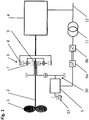
- Fig. 1 shows the principle of a differential system for a drive train using the example of a pump.
- the working machine 1 is the rotor of a pump, which is driven by a drive machine 4 via a drive shaft 2 and a differential gear 3.
- the drive machine 4 is preferably a medium-voltage three-phase machine, which is connected to a network 12, which in the example shown is a medium-voltage network due to a medium-voltage three-phase machine.
- the voltage level selected depends on the application and, above all, the performance level of the drive machine 4 and can have any desired voltage level without affecting the basic function of the system according to the invention.
- a design-specific operating speed range results in accordance with the number of pole pairs of the drive machine 4.
- the operating speed range is that speed range in which the drive machine 4 can deliver a defined or desired or required torque or, in the case of an electric drive machine, can be synchronized with the network 12.
- a planet carrier 7 is connected to the drive shaft 2, a drive machine 4 with a ring gear 8 and a sun gear 9 of the differential gear 3 with the differential drive 5.
- the core of the differential system in this embodiment is thus a simple planetary gear stage with three drives and outputs, whereby an output is connected to the drive shaft 2 of the work machine 1, a first drive is connected to the drive machine 4 and a second drive is connected to the differential drive 5.
- the drive train thus essentially consists of the drive machine 4, differential gear 3 and differential drive 5.
- an adaptation gear 10 is implemented between the sun gear 9 and the differential drive 5.
- the adaptation gear 10 can also be multi-stage, for example, or be designed as a toothed belt or chain drive and / or planetary stage or angular gear.
- a motor brake 13 is connected to the differential drive 5, which brakes the differential drive 5 if necessary.
- the differential drive 5 is electrically connected to the network 12 by means of a preferably low-voltage frequency converter consisting of a rectifier or inverter 6a on the differential drive side and a network-side inverter or rectifier 6b, and a transformer 11, depending on the operating mode as a motor or generator .
- the transformer compensates for any existing voltage differences between the network 12 and the network-side inverter or rectifier 6b and can be omitted if the voltage between the drive machine 4, the network-side inverter or rectifier 6b and the network 12 is the same.
- the rectifier or inverter 6a and the inverter or rectifier 6b are connected by a direct current intermediate circuit and can be locally separated if necessary, the rectifier or inverter 6a on the differential drive side preferably being positioned as close as possible to the differential drive 5.
- the frequency converter can also be redundant, as in the WO 2012/001138 A proposed to be executed.
- An essential advantage of a differential system is that the drive machine 4, if it is an electrical machine, can be connected directly, that is to say without power electronics, to a network 12.
- the compensation between the variable rotor speed and the fixed speed of the network-connected drive machine 4 is realized by the variable-speed differential drive 5.
- Torque Differential drive Torque drive shaft * y / x , wherein the size factor y / x is a measure of the transmission ratios in the differential gear 3 and in the matching gear 10.
- the power of the differential drive 5 is essentially proportional to the product of the percentage deviation of the pump speed from its base speed x drive shaft power. Accordingly, a large speed range basically requires a correspondingly large dimensioning of the differential drive 5. This also shows the reason why differential systems are particularly well suited for small speed ranges, but in principle any speed range can be implemented.
- Fig. 2 Figure 3 shows one embodiment of a differential system that can be used with the invention.
- the drive train shown here also shows as in Fig. 1 a drive machine 4, a differential gear 3, a differential drive 5 and a frequency converter 6a, 6b, which is connected to a network 12 by means of a transformer 11.
- a work machine 1 is driven by means of a drive shaft 2.
- the transformer compensates for existing voltage differences between the network 12 and the differential drive 5 and can be omitted if the voltages are equal.
- the engine brake 14 is in this embodiment variant (as an alternative to the position of the engine brake 13 in Fig. 1 ) positioned between differential drive 5 and sun gear 9. It is connected, for example, to a toothed wheel shaft of the adaptation gear 10, but can in principle be arranged anywhere between the sun wheel 9 and differential drive 5, depending on the structural requirements. This means that the differential drive 5 can be dismantled for any repairs that may be necessary and the differential system can still operate at a basic speed "T" ( Fig. 4 ) continue to be operated.
- any type of non-positive and / or positive locking or lock can be provided.
- This lock is either provided as standard or is used if necessary.
- frequency converters 6a, 6b are more error-prone than electrical machines and have a significantly shorter service life. For this reason, it is important for a system operator to have a solution that enables operation to continue as soon as a frequency converter is no longer operational.
- This object is achieved according to the invention in that, in the event of a fault in the frequency converter 6a, 6b, it is separated from the differential drive 5 and the differential drive 5 is connected directly (or if necessary via a transformer 11) to the network 12 via a line 15.
- two switches 16, 17 are provided with which the differential drive 5 can alternatively be switched to the frequency converter 6a, 6b or to the line 15. In this way, at least one speed-fixed operating point can be set.
- the differential drive 5 is designed as a pole-changing three-phase machine, at least two, but if necessary, several synchronous speeds can be achieved by accommodating two or more electrically separate windings in the stator of the three-phase machine. Pairings of 4 and 6 or 4 and 8 poles are common. For example, in a 50Hz network, a 4-pole three-phase machine has a synchronous speed of 1,500 rpm, a 6-pole three-phase machine has a synchronous speed of 1,000 rpm and an 8-pole three-phase machine has a synchronous speed of 750 rpm.
- two or more fixed-speed operating points for the working machine (1) can be implemented. But even if the differential drive 5 cannot be pole-changing, the drive train can still be operated with the (one) synchronous speed.
- Another fixed-speed operating point for the machine (1) is at the base speed "T". This is the operating point at which the sun gear (9) is at a standstill, for example when the brakes 13, 14 are activated.
- Fig. 3 shows another embodiment of a differential system that can be used with the invention.
- the differential system is the same as in Fig. 2 shown constructed.
- the differential drive 5 designed as a three-phase machine, can be connected to the network 12 with different rotating field directions.
- the motor terminals U2, V2 and W2 are bridged and with the right rotating field: L1 to U1, L2 to V1 and L3 to W1, or with the left rotating field: L1 to W1, L2 to V1 and L3 to U1.
- the differential drive 5 works either as a motor (power flow direction "a") or as a generator (power flow direction "b"). This results in a further fixed-speed operating point for the machine 1. If the three-phase machine is pole-changing, more additional, fixed-speed operating points are obtained accordingly.
- the line 15 symbolizes the rotating field with which the differential drive 5 rotates in the motor area and thus the power flow goes in the direction of "a”.
- only one of the two lines 15, 18 can exist and to change the direction of rotation, for example, the outer conductors can be connected as described.
- At least three speed-fixed operating points can be implemented - using a pole-changing three-phase machine at least 5.
- the frequency converter 6a, 6b can be eliminated and the machine 1 operated with several speed-fixed operating points.
- FIGS. 1 to 3 show a differential system in which the first drive is connected to a ring gear, the output is connected to a planet carrier and the second drive is connected to a sun gear.
- the second drive can be connected to the planet carrier 7
- the first drive can be connected to the ring gear 8
- the output can be connected to the sun gear 9.
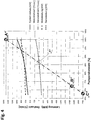
- Fig. 4 shows the speed and power parameters of a differential system according to the invention, for example for a pump.
- the illustration shows power and speed values for a pump as a work machine 1, a drive machine 4 and a differential drive 5, each plotted against the speed values of the drive shaft 2 (“pump speed”).
- the drive machine 4 is connected to the network 12 and thus its speed (“motor speed") is constant - in the example shown approx. 1,500 rpm for a four-pole three-phase machine in a 50 Hz network.
- the working speed range for the drive shaft 2 goes from 68% to 100%, with 100% being the selected nominal or maximum point of the differential system.
- the speed of the differential drive 5 (“servo speed") ranges from -2,000 1 / min to 1,500 1 / min, the speed of approx. 1,500 1 / min being the synchronous speed selected for this example (also in the example shown a 4-pole three-phase machine in the 50 Hz network) of the differential drive 5.
- the differential drive 5 delivers its nominal torque.
- the nominal torque refers to the maximum torque that a three-phase machine can permanently provide under the given ambient conditions.
- Fig. 4 shows that the differential drive 5 is operated as a generator (-) and as a motor (+). Since the maximum required power of the differential drive 5 in the generator (-) range (approx. 110kW) is less than that in the motor (+) range (approx. 160kW), the differential drive 5 can be operated permanently in the generator (-) range in the so-called field weakening range with which a higher speed (above its synchronous speed) - but with reduced torque - can be realized for the differential drive 5. In this way, the speed range for the machine 1 can be expanded in a simple manner up to the operating point "C". Is the differential system according to Fig. 3 configured, the operating points "A" and "B" can be approached by changing the rotating field.
- the frequency converter can be designed as a so-called 2Q system (2-quadrant frequency converter), as a result of which the differential system is then only designed for the motor (+) area.
- the line-side rectifier 6b can thus also be designed, for example, as a simple diode rectifier.
- the machine 1 can also be used here in the case of a direct connection according to the invention of the differential drive 5 to the network 12 (without frequency converters 6a, 6b - corresponds to an embodiment according to the invention as shown in FIG Fig. 2 described) operate at both their minimum and their maximum point.
- differential drive 5 is designed as a pole-changing three-phase machine, speeds between minimum and maximum speed can also be achieved by switching the number of pole pairs accordingly.
- the point "T” in Fig. 4 marks the so-called “basic speed” of the drive shaft 2, at which the speed of the differential drive 5 is zero. Ideally, this point will turn into a "T” Work area in which the system is operated over a large period of time.
- the motor brake 13, 14 can be activated, so that the differential drive 5 does not have to be operated and consequently losses and wear associated therewith are avoided.
- the drive is driven in parallel by the drive machine 4 and the differential drive 5. The sum of both powers is the drive power for drive shaft 2 ("system power”) minus any system losses.
- the drive machine 4 In the generator (-) range, the drive machine 4 must compensate for the output of the differential drive 5 ("servo output"), whereby the total system output (“system output”) is the drive output of the drive machine 4 ("motor output”) minus the output of the differential drive 5. This means that the motor (+) range is better in terms of efficiency.
- the power flow via the differential drive 5 is smaller and thus the overall system efficiency is higher, the closer the pump speed ("pump speed") is to the base speed "T". Since the required drive power also increases with increasing pump speed, the required size of the drive machine 4 can be reduced by the size of the differential drive 5 by the parallel drive of the drive machine 4 and the differential drive 5 compared to a drive according to the prior art.
- the individual measures described for locking or operating the differential drive 5 at the operating points described can of course be used either individually or in any combination so that, depending on the application, at least one operating point but also any number of operating points for the drive train can be implemented, even if the frequency converter or even the differential drive is out of order.
- the working machine 1 is in Figs. 1 to 3 a pump is shown symbolically as an example.
- the concept described here can, however, also be used with drives for all other types of work machines, such as compressors, fans and conveyor belts, mills, crushers, etc. or energy recovery systems and the like.
- the drive machine 4 works essentially in generator mode and consequently the power flow in the entire drive train is reversed.
- the drive machine 4 is preferably connected to the network first, while the second drive (sun shaft 9 or differential drive 5) preferably by means of a service brake 13, 14 or remains braked by means of a lock.
- the working machine 1 thus reaches the operating point “T”.
- the differential system is then either operated at this operating point or the differential drive 5 is connected to the network.
- that speed is set at the differential drive 5 which results from the selected / preset rotating field direction or number of pole pairs on the differential drive 5.
- the operating point subsequently established for the machine 1 results in accordance with the rotating field direction or number of pole pairs selected for the differential drive 5 and the transmission ratios of the differential gear 3 and the adaptation gear stage 10.
- the system can of course also be started up in any other way, for example by connecting the drive machine 4 and the differential drive 5 to the mains at the same time or that the differential drive 5 and then the drive machine 4 connected to the grid.
- the differential drive 5 can also be switched on before, at the same time with and after the drive machine.
- the working machine 1 cannot be operated continuously with variable speed.
- the work machine 1 is, for example, a conveying device in a line system, a throttle or a flap or a bypass or a valve can be arranged in the line system after the work machine 1. In this way, if necessary, the flow rate can be regulated between the likewise fixed flow rates or delivery heads which are established due to the fixed speeds of the differential system.
- the second drive of the differential system is braked. If one of the operating points "B” or “A” is to be approached, then in a further, preferably parallel step, the Differential drive 5 connected directly to the network 12. If this happens sufficiently quickly, activation of one of the delay devices described above can be dispensed with. In addition, if you do not have the option of approaching operating point "B", you save yourself a reversing contactor circuit, for example, and either preferably approach operating point "T” or alternatively operating point “A” by using differential drive 5 at the required speed Direction of rotation of the stator rotating field connects to the network 12.
- the delay device can also be used for speed-controlled network synchronization of the differential drive 5 by activating it so that the synchronous speed of the differential drive 5 is essentially set before it is connected to the network 12.
- a delay device can also be used to implement continuous, variable-speed operation in the system operating range between operating points "C" and "T". This is useful, for example, if the differential drive 5 fails or the power of the differential drive 5 or the inverter 6a, 6b is insufficient to provide the required operating torque.
- Fig. 5 shows a characteristic curve of a three-phase machine (for example, can be used as a differential drive 5) in which the rotating field is connected to a network in such a way that according to the invention according to FIG. Fig. 4 the operating point "A" (in Fig. 5 "Nominal point” of the three-phase machine) would set. In the system operating range between points "C" and "T", the three-phase machine would move along the dotted part of the characteristic curve ("countercurrent braking range"). From the representation in Fig. 5 it can be seen that the torque (M i / M iK ) that can typically be achieved by a three-phase machine in the counter-current braking range is significantly lower than its nominal torque.
- M i / M iK the torque that can typically be achieved by a three-phase machine in the counter-current braking range is significantly lower than its nominal torque.
- the torque in the countercurrent braking range can, however, be increased by, for example, a special design of the rotor bars of the three-phase machine. If this is not enough, set the differential system to a desired, fixed-speed operating point to regulate, a delay device, for example a brake already described, is preferably additionally activated. This is also preferred if the differential drive 5 in the failure of the frequency converter 6a, 6b in the system operating range above "T" (motor (+) range) in the generator (-) range of the map according to. Fig. 4 comes.
- the delay device is preferably activated in both cases until, on the one hand, the differential drive 5 is directly connected to the network and, on the other hand, the system operating speed is in the generator (-) range of the characteristic field ( ⁇ "T").
- Any operating points with a reduced delivery rate of the machine 1 between the fixed-speed operating points that can be implemented without a frequency converter 6a, 6b are regulated with a throttle device.
- This throttle device can, for example, be a throttle, a flap, a bypass or a valve, which can, for example, be positioned in the line system after the working machine 1. If the work machine 1 is, for example, a mechanical drive, the throttle device can be, for example, a brake, a retarder or the like, in order to reduce the power of the drive machine 1.
- the differential drive 5 is preferably always used to set the next higher (in the direction of higher speed or delivery rate) fixed-speed operating point ("B", "T” or "A") and, by means of the throttle device, an operating point below approached.
- the differential drive 5 is preferably either connected directly to the network 12 so that the operating point "A” is approached, or it is operating point “T” is set by braking the second drive of the differential system.
- the differential drive 5 is preferably connected directly to the network 12 in such a way that the operating point "A” is approached directly without a delay device of the second drive of the differential system has to be activated (if, as described above, the system operating speed does not fall below "T", for example).
Landscapes
- Engineering & Computer Science (AREA)
- Power Engineering (AREA)
- General Engineering & Computer Science (AREA)
- Mechanical Engineering (AREA)
- Structure Of Transmissions (AREA)
- Control Of Multiple Motors (AREA)
Description
- Die Erfindung betrifft ein Verfahren zum Betreiben eines Triebstranges mit einer Antriebswelle, einer Antriebsmaschine und mit einem Differenzialgetriebe mit drei An- bzw. Abtrieben, wobei ein Abtrieb mit der Antriebswelle ein Antrieb mit der Antriebsmaschine und ein zweiter Antrieb mit einem elektrischen Differenzialantrieb verbunden ist.
- Ein derartiges Verfahren, bei dem drehzahlstabile Betriebspunkte einerseits bei einer Drehzahl des Differenzialantriebs von Null und andererseits bei einem Übersetzungsverhältnis des Differenzialgetriebes gleich 1 möglich sind, ist aus der
WO 2014/183142 A1 bekannt. - Aus der
DE 195 02 224 C1 ist ein Hybridantrieb, insbesondere für Kraftfahrzeuge, bekannt, bei dem ein Frequenzumrichter zwischen einem Generator und einem elektrischen Antrieb für einen Notbetrieb mittels einer Umgehungsleitung überbrückt werden kann. - Eine häufig gestellte Anforderung an Arbeitsmaschinen, wie Fördereinrichtungen, z.B. Pumpen, Kompressoren und Ventilatoren, oder wie Mühlen, Brecher, Fahrzeuge, oder wie Energiegewinnungsanlagen usw., ist ein effizienter drehzahlvariabler Betrieb.
- Im Weiteren werden elektrische Maschinen als Beispiel für in diesem Zusammenhang eingesetzte Antriebsmaschinen herangezogen, das Prinzip gilt aber für alle möglichen Arten von Antriebsmaschinen, so wie z.B. für Verbrennungskraftmaschinen.
- Die am häufigsten verwendeten elektrischen Antriebe sind heutzutage Drehstrommaschinen, wie z.B. Asynchronmotore und Synchronmotore. Um diese drehzahlvariabel betreiben zu können, werden sie in Kombination mit einem Frequenzumrichter an ein Netz angebunden. Damit kann man zwar einen drehzahlvariablen Betrieb des Antriebs realisieren, die Lösung ist jedoch teuer und mit wesentlichen Wirkungsgradeinbußen verbunden.
- Eine vergleichsweise kostengünstigere und auch bezüglich Wirkungsgrad bessere Alternative ist der Einsatz von Differenzialsystemen - beispielsweise gemäß
AT 507 394 A - Frequenzumrichter sind jedoch fehleranfälliger als elektrische Maschinen und haben eine wesentlich kürzere Nutzungsdauer.
- Der Erfindung liegt daher die Aufgabe zu Grunde, ein Verfahren der eingangs genannten Art anzugeben, mit dem ein Betrieb des Triebstranges ohne Frequenzumrichter möglich ist.
- Gelöst wird diese Aufgabe mit einem Verfahren mit den Merkmalen des Anspruchs 1.
- Wenn der Differenzialantrieb alternativ über einen Frequenzumrichter und eine parallel zum Frequenzumrichter liegende Leitung an ein Netz schaltbar ist, liegt der Vorteil erfindungsgemäß darin, dass der Triebstrang wie an sich bekannt über einen Frequenzumrichter betrieben werden kann, dass aber auch wenn der Frequenzumrichter einen Defekt hat bzw. ausfällt, der Triebstrang weiter betrieben werden kann, auch wenn dessen Drehzahlvariabilität wegfällt oder eingeschränkt ist. Bevorzugte Ausführungsformen der Erfindung sind Gegenstand der Unteransprüche.
- Nachfolgend werden bevorzugte Ausführungsformen der Erfindung mit Bezug auf die angeschlossenen Zeichnungen erläutert. Es zeigt:
- Fig. 1
- das Prinzip eines Differenzialsystems für einen Antrieb einer Pumpe gemäß Stand der Technik,
- Fig. 2
- eine erste Ausführungsform eines Differenzialsystems, das bei der Erfindung verwendet werden kann,
- Fig. 3
- eine weitere Ausführungsform eines Differenzialsystems, das bei der Erfindung verwendet werden kann,
- Fig. 4
- die Drehzahl- und Leistungsparameter eines erfindungsgemäßen Differenzialsystems einer Pumpen und
- Fig. 5
- eine Kennlinie einer Drehstrommaschine.
-
Fig. 1 zeigt das Prinzip eines Differenzialsystems für einen Triebstrang am Beispiel einer Pumpe. Dabei ist die Arbeitsmaschine 1 der Rotor einer Pumpe, welcher über eine Antriebswelle 2 und ein Differenzialgetriebe 3 von einer Antriebsmaschine 4 angetrieben wird. Die Antriebsmaschine 4 ist vorzugsweise eine Mittelspannungs-Drehstrommaschine, welche an ein Netz 12, welches im gezeigten Beispiel aufgrund einer Mittelspannungs-Drehstrommaschine ein Mittelspannungsnetz ist, angeschlossen wird. Das gewählte Spannungsniveau hängt jedoch vom Einsatzfall und vor allem dem Leistungsniveau der Antriebsmaschine 4 ab und kann, ohne Einfluss auf die Grundfunktion des erfindungsgemäßen Systems, jedes gewünschte Spannungsniveau haben. Entsprechend der Polpaarzahl der Antriebsmaschine 4 ergibt sich ein bauartspezifischer Betriebsdrehzahlbereich. Der Betriebsdrehzahlbereich ist dabei jener Drehzahlbereich, in dem die Antriebsmaschine 4 ein definiertes oder gewünschtes bzw. erforderliches Drehmoment liefern kann bzw. im Falle einer elektrischen Antriebsmaschine mit dem Netz 12 synchronisiert werden kann. Ein Planetenträger 7 ist mit der Antriebswelle 2 verbunden, eine Antriebsmaschine 4 mit einem Hohlrad 8 und ein Sonnenrad 9 des Differenzialgetriebes 3 mit dem Differenzialantrieb 5. Der Kern des Differenzialsystems ist in dieser Ausführungsform somit eine einfache Planetengetriebestufe mit drei An- bzw. Abtrieben, wobei ein Abtrieb mit der Antriebswelle 2 der Arbeitsmaschine 1, ein erster Antrieb mit der Antriebsmaschine 4 und ein zweiter Antrieb mit dem Differenzialantrieb 5 verbunden ist. - Der Triebstrang besteht damit im Wesentlichen aus Antriebsmaschine 4, Differenzialgetriebe 3 und Differenzialantrieb 5.
- Um den Drehzahlbereich des Differenzialantriebs 5 optimal anpassen zu können, wird ein Anpassungsgetriebe 10 zwischen dem Sonnenrad 9 und dem Differenzialantrieb 5 implementiert. Alternativ zur gezeigten Stirnradstufe kann das Anpassungsgetriebe 10 beispielsweise auch mehrstufig sein bzw. als Zahnriemen oder Kettentrieb und/oder Planetenstufe oder Winkelgetriebe ausgeführt werden. Mit dem Anpassungsgetriebe 10 kann man darüber hinaus einen Achsversatz für den Differenzialantrieb 5 realisieren, der aufgrund der koaxialen Anordnung der Arbeitsmaschine 1 und der Antriebsmaschine 4 eine einfache Ausführung des Differenzialantriebes 5 ermöglicht. Mit dem Differenzialantrieb 5 ist eine Motorbremse 13 verbunden, welche den Differenzialantrieb 5 bei Bedarf bremst. Elektrisch ist der Differenzialantrieb 5 mittels eines vorzugsweisen Niederspannungs-Frequenzumrichters, bestehend aus einem - je nach Betriebsart als Motor oder Generator - differentialantriebsseitigen Gleich- bzw. Wechselrichter 6a und einem netzseitigen Wechsel- bzw. Gleichrichter 6b, und einem Transformator 11 an das Netz 12 angebunden. Der Transformator gleicht allfällige vorhandene Spannungsdifferenzen zwischen dem Netz 12 und dem netzseitigen Wechsel- bzw. Gleichrichter 6b aus und kann bei Spannungsgleichheit zwischen der Antriebsmaschine 4, dem netzseitigen Wechsel- bzw. Gleichrichter 6b und dem Netz 12 entfallen. Der Gleich- bzw. Wechselrichter 6a und der Wechsel- bzw. Gleichrichter 6b sind durch einen Gleichstromzwischenkreis verbunden und können bei Bedarf örtlich getrennt sein, wobei vorzugsweise der differentialantriebsseitige Gleich- bzw. Wechselrichter 6a so nah wie möglich beim Differenzialantrieb 5 positioniert ist.
- Um eine hohe Ausfallsicherheit des Gesamtsystems zu erzielen, kann der Frequenzumrichter auch redundant, wie z.B. in der
WO 2012/001138 A vorgeschlagen, ausgeführt werden. - Wesentlicher Vorteil eines Differenzialsystems ist, dass die Antriebsmaschine 4, sofern es sich um eine elektrische Maschine handelt, direkt, das heißt ohne Leistungselektronik, an ein Netz 12 angebunden werden kann. Der Ausgleich zwischen variabler Rotordrehzahl und fixer Drehzahl der netzgebundenen Antriebsmaschine 4 wird durch den drehzahlvariablen Differenzialantrieb 5 realisiert.
- Die Drehmomentgleichung für das Differenzialsystem lautet:

-
Fig. 2 zeigt eine Ausführungsform eines Differenzialsystems, das bei der Erfindung verwendet werden kann. Der gezeigte Triebstrang weist auch hier wie inFig. 1 eine Antriebsmaschine 4, ein Differenzialgetriebe 3, einen Differenzialantrieb 5 und einen Frequenzumrichter 6a, 6b auf, welcher mittels eines Transformators 11 an ein Netz 12 angeschlossen ist. Auch hier wird eine Arbeitsmaschine 1 mittels einer Antriebswelle 2 angetrieben. - Der Transformator gleicht bei Bedarf vorhandene Spannungsdifferenzen zwischen dem Netz 12 und dem Differenzialantrieb 5 aus und kann bei Spannungsgleichheit entfallen.
- Die Motorbremse 14 ist in dieser Ausführungsvariante (alternativ zur Position der Motorbremse 13 in
Fig. 1 ) zwischen Differenzialantrieb 5 und Sonnenrad 9 positioniert. Sie ist beispielhaft mit einer Zahnradwelle des Anpassungsgetriebes 10 verbunden, kann aber entsprechend den konstruktiven Erfordernissen grundsätzlich überall zwischen Sonnenrad 9 und Differenzialantrieb 5 angeordnet sein. Damit kann der Differenzialantrieb 5 für eine allfällig notwendige Reparatur abgebaut und das Differenzialsystem trotzdem mit einer Grunddrehzahl "T" (Fig. 4 ) weiter betrieben werden. - Alternativ zur Motorbremse 13 und/oder 14 kann jede Art einer kraft- und/oder formschlüssigen Arretierung bzw. Sperre vorgesehen werden. Diese Arretierung ist entweder standardmäßig vorgesehen oder wird bei Bedarf eingesetzt.
- Frequenzumrichter 6a, 6b sind jedoch, wie schon eingangs erwähnt, fehleranfälliger als elektrische Maschinen und haben eine wesentlich kürzere Nutzungsdauer. Aus diesem Grund ist es für einen Anlagenbetreiber wichtig eine Lösung zu haben, welche eine Fortsetzung des Betriebes ermöglicht, sobald ein Frequenzumrichter nicht (mehr) betriebsbereit ist.
- Gelöst wird diese Aufgabe erfindungsgemäß dadurch, dass man, im Fehlerfall des Frequenzumrichters 6a, 6b, diesen vom Differenzialantrieb 5 trennt und den Differenzialantrieb 5 direkt (oder sofern erforderlich über einen Transformator 11) über eine Leitung 15 mit dem Netz 12 verbindet. Dazu sind zwei Schalter 16, 17 vorgesehen, mit denen der Differenzialantrieb 5 alternativ an den Frequenzumrichter 6a, 6b oder an die Leitung 15 geschalten werden kann. Damit kann wenigstens ein drehzahlfester Betriebspunkt eingestellt werden.
- Wird der Differenzialantrieb 5 als polumschaltbare Drehstrommaschine ausgeführt, können mindestens zwei, jedoch bei Bedarf auch mehrere Synchrondrehzahlen realisiert werden, indem man zwei oder mehrere elektrisch getrennte Wicklungen im Stator der Drehstrommaschine unterbringt. Üblich sind Paarungen von 4 und 6 oder 4 und 8 Polen. So hat z.B. in einem 50Hz-Netz eine 4-pol Drehstrommaschine eine Synchrondrehzahl von 1.500 1/min, eine 6-pol Drehstrommaschine eine Synchrondrehzahl von 1.000 1/min und eine 8-polige Drehstrommaschine eine Synchrondrehzahl von 750 1/min.
- D.h. man kann damit, entsprechend einer implementierten Polumschaltbarkeit, zwei oder mehrere drehzahlfeste Betriebspunkte für die Arbeitsmaschine (1) realisieren. Aber auch wenn der Differenzialantrieb 5 nicht polumschaltbar ist, kann der Triebstrang immer noch mit der (einen) Synchrondrehzahl weiter betrieben werden. Ein weiterer drehzahlfester Betriebspunkt für die Arbeitsmaschine (1) liegt bei der Grunddrehzahl "T". Das ist der Betriebspunkt, bei dem das Sonnenrad (9) steht, z.B. wenn die Bremse 13, 14 aktiviert ist.
-
Fig. 3 zeigt eine weitere Ausführungsform eines Differenzialsystems, das bei der Erfindung verwendet werden kann. Grundsätzlich ist das Differenzialsystem gleich wie inFig. 2 dargestellt aufgebaut. In dieser erfindungsgemäßen Erweiterung des Systems, kann der als Drehstrommaschine ausgeführte Differenzialantrieb 5 mit unterschiedlicher Drehfeldrichtung mit dem Netz 12 verbunden werden. - Zur Änderung der Drehrichtung muss der Drehsinn des Ständerdrehfeldes geändert werden. Beim Betrieb am Drehstromnetz genügt dabei das Vertauschen zweier Außenleiter, z. B. der Außenleiter L1 und L3. Eine übliche Schaltung dazu ist die Wende-Schützschaltung.
- In der praktischen Anwendung werden die Motorklemmen U2, V2 und W2 gebrückt und beim rechten Drehfeld: L1 an U1, L2 an V1 und L3 an W1, bzw. beim linken Drehfeld: L1 an W1, L2 an V1 und L3 an U1 geschaltet. Durch die Änderung des Drehfeldes arbeitet der Differenzialantrieb 5 entweder als Motor (Leistungsflussrichtung "a") oder als Generator (Leistungsflussrichtung "b"). Damit ergibt sich für die Arbeitsmaschine 1 ein weiterer drehzahlfester Betriebspunkt. Ist die Drehstrommaschine polumschaltbar, erhält man entsprechend mehr zusätzliche drehzahlfeste Betriebspunkte.
- Bei der Ausführungsform von
Fig. 3 symbolisiert die Leitung 15 das Drehfeld, mit dem der Differenzialantrieb 5 in den motorischen Bereich dreht und somit der Leistungsfluss Richtung "a" geht. Eine weitere Leitung 18, welche mittels Schalter 19 mit dem Differenzialantrieb 5 verbunden werden kann, symbolisiert das Drehfeld, mit dem der Differenzialantrieb 5 in den generatorischen Bereich dreht und somit der Leistungsfluss Richtung "b" geht. In der Praxis kann natürlich auch nur eine der beiden Leitungen 15, 18 existieren und zur Änderung der Drehrichtung z.B. die Außenleiter wie beschrieben verschaltet werden. - D.h. in einem Differenzialsystem gem.
Fig. 3 sind zumindest drei drehzahlfeste Betriebspunkte realisierbar - unter Einsatz einer polumschaltbaren Drehstrommaschine mindestens 5. In einer vereinfachten Ausführungsform eines Differenzialsystems kann der Frequenzumrichter 6a, 6b eliminiert und die Arbeitsmaschine 1 mit mehreren drehzahlfesten Betriebspunkten betrieben werden. -
Fig. 1 bis Fig. 3 zeigen ein Differenzialsystem in dem der erste Antrieb mit einem Hohlrad, der Abtrieb mit einem Planetenträger und der zweite Antrieb mit einem Sonnenrad verbunden sind. In einer weiteren Variante kann der zweite Antrieb mit dem Planetenträger 7, der erste Antrieb mit dem Hohlrad 8 und der Abtrieb mit dem Sonnenrad 9 verbunden werden. Weitere alternative Kombinationen sind ebenfalls von der Erfindung erfasst. -
Fig. 4 zeigt die Drehzahl- und Leistungsparameter eines erfindungsgemäßen Differenzialsystems, beispielsweise für eine Pumpe. Die Darstellung zeigt Leistungs- und Drehzahlwerte für eine Pumpe als Arbeitsmaschine 1, eine Antriebsmaschine 4 und einen Differenzialantrieb 5 jeweils aufgetragen über den Drehzahlwerten der Antriebswelle 2 ("Pumpendrehzahl"). Die Antriebsmaschine 4 ist mit dem Netz 12 verbunden und damit ist ihre Drehzahl ("Motordrehzahl") konstant - in dem gezeigten Beispiel ca. 1.500 1/min für eine vierpolige Drehstrommaschine in einem 50 Hz-Netz. Der Arbeitsdrehzahlbereich für die Antriebswelle 2 geht von 68% bis 100%, wobei bei 100% der gewählte Nenn- bzw. Maximalpunkt des Differenzialsystems ist. Entsprechend dem Übersetzungsverhältnis des Differenzialsystems geht dabei die Drehzahl des Differenzialantriebes 5 ("Servodrehzahl") von -2.000 1/min bis 1.500 1/min, wobei die Drehzahl von ca. 1.500 1/min die für dieses Beispiel gewählte Synchrondrehzahl (im dargestellten Beispiel ebenfalls eine 4-polige Drehstrommaschine im 50Hz-Netz) des Differenzialantriebes 5 ist. In etwa bei dieser Synchrondrehzahl liefert der Differenzialantrieb 5 sein Nenndrehmoment. Das Nenndrehmoment bezeichnet dabei jenes maximale Drehmoment, welches eine Drehstrommaschine unter den gegebenen Umgebungsbedingungen dauerhaft zur Verfügung stellen kann. -
Fig. 4 zeigt, dass der Differenzialantrieb 5 generatorisch (-) und motorisch (+) betrieben wird. Da die maximal erforderliche Leistung des Differenzialantriebes 5 im generatorischen (-) Bereich (ca. 110kW) geringer als die im motorischen (+) Bereich (ca. 160kW) ist, kann der Differenzialantrieb 5 dauerhaft im generatorischen (-) Bereich im sogenannten Feldschwächebereich betrieben werden, womit für den Differenzialantrieb 5 eine höhere (über dessen Synchrondrehzahl liegende) Drehzahl - jedoch mit reduziertem Drehmoment - realisierbar ist. Damit kann auf einfache Weise der Drehzahlbereich für die Arbeitsmaschine 1 bis zum Betriebspunkt "C" erweitert werden. Ist das Differenzialsystem gemäßFig. 3 konfiguriert, so können durch Änderung des Drehfeldes die Arbeitspunkte "A" und "B" angefahren werden. D.h. das Differenzialsystem kann im Falle einer erfindungsgemäßen direkten Anbindung des Differenzialantriebes 5 an das Netz 12 (ohne Frequenzumrichter 6a, 6b - entspricht einer erfindungsgemäßen Ausführung wie zuFig. 3 beschrieben) Betriebspunkte über fast den gesamten Betriebsdrehzahlbereich der Arbeitsmaschine 1 realisieren. - In einer besonders einfachen Ausführungsform eines Differenzialsystems kann der Frequenzumrichter als sogenanntes 2Q-System (2-Quadranten-Frequenzumrichter) ausgelegt sein, wodurch das Differenzialsystem dann nur für den motorischen (+)Bereich konzeptioniert ist. Damit kann der netzseitige Gleichrichter 6b z.B. auch als einfacher Diodengleichrichter ausgeführt werden. In dieser Auslegungsvariante eines Differenzialsystems, kann man auch hier die Arbeitsmaschine 1 im Falle einer erfindungsgemäßen direkten Anbindung des Differenzialantriebes 5 an das Netz 12 (ohne Frequenzumrichter 6a, 6b - entspricht einer erfindungsgemäßen Ausführung wie zu
Fig. 2 beschrieben) sowohl in ihrem Minimal- als auch in ihrem Maximalpunkt betreiben. - Ist der Differenzialantrieb 5 als polumschaltbare Drehstrommaschine ausgelegt, kann man durch entsprechende Umschaltung der Polpaarzahl auch Drehzahlen zwischen Minimal- und Maximaldrehzahl realisieren.
- Der Punkt "T" in
Fig. 4 markiert die sogenannte "Grunddrehzahl" der Antriebswelle 2, bei der die Drehzahl des Differenzialantriebes 5 gleich Null ist. Idealerweise wird dieser Punkt "T" in einen Arbeitsbereich gelegt, in dem die Anlage über große Zeitanteile betrieben wird. In diesem Betriebspunkt kann die Motorbremse 13, 14 aktiviert werden, womit der Differenzialantrieb 5 nicht betrieben werden muss und in weiterer Folge damit zusammenhängende Verluste und Verschleiß vermieden werden. Im motorischen (+) Bereich des Kennfeldes wird der Antrieb parallel von der Antriebsmaschine 4 und dem Differenzialantrieb 5 angetrieben. Die Summe beider Leistungen ist die Antriebsleistung für die Antriebswelle 2 ("Systemleistung") abzüglich anfallender Systemverluste. Im generatorischen (-) Bereich muss die Antriebsmaschine 4 die Leistung des Differenzialantriebes 5 ("Servoleistung") kompensieren, wodurch die Systemgesamtleistung ("Systemleistung") die Antriebsleistung der Antriebsmaschine 4 ("Motorleistung") abzüglich der Leistung des Differenzialantriebes 5 ist. D.h., dass wirkungsgradmäßig der motorische (+) Bereich besser ist. - Grundsätzlich ist festzustellen, dass der Leistungsfluss über den Differenzialantrieb 5 umso kleiner und somit der Systemgesamtwirkungsgrad umso höher ist, je näher die Pumpendrehzahl ("Pumpendrehzahl") bei der Grunddrehzahl "T" liegt. Da mit zunehmender Pumpendrehzahl auch die erforderliche Antriebsleistung steigt, kann jedoch im Vergleich zu einem Antrieb gemäß Stand der Technik durch den parallelen Antrieb der Antriebsmaschine 4 und des Differenzialantrieb 5 die erforderliche Größe der Antriebsmaschine 4 um die Größe des Differenzialantriebes 5 reduziert werden.
- Die einzelnen beschriebenen Maßnahmen zum Sperren bzw. zum Betreiben des Differenzialantriebes 5 bei den beschriebenen Betriebspunkten können selbstverständlich entweder einzeln oder in beliebiger Kombination miteinander eingesetzt werden, sodass sich je nach Anwendungsfall wenigstens ein Betriebspunkt aber auch beliebig viele Betriebspunkte für den Triebstrang realisieren lassen, auch wenn der Frequenzumrichter oder sogar der Differenzialantrieb außer Betrieb ist.
- Während des Betriebes des Triebstranges kann auch zwischen den beschriebenen Betriebspunkten gewechselt werden, womit ein drehzahlvariabler Betrieb möglich wird. Bei diesen Betriebspunkten wird der Differenzialantrieb 5, sofern er in Betrieb ist, jeweils mit unterschiedlichen Drehzahlen betrieben, bei denen es sich aber jeweils um Synchrondrehzahlen handelt, da der Differenzialantrieb direkt bzw. gegebenenfalls nur über den Transformator 11 an das Netz 12 angeschlossen ist.
- Als Arbeitsmaschine 1 ist in
Fig. 1 bis 3 beispielhaft symbolisch eine Pumpe dargestellt. Das hier beschriebene Konzept ist jedoch auch bei Antrieben für alle anderen Arten vom Arbeitsmaschinen anwendbar, wie z.B. Kompressoren, Ventilatoren und Förderbänder, Mühlen, Brecher, etc. oder Energiegewinnungsanlagen und dergleichen. - Im Falle des Einsatzes des erfindungsgemäßen Systems bei einer Energiegewinnungsanlage arbeitet die Antriebsmaschine 4 im Wesentlichen im generatorischen Betrieb und demzufolge dreht sich der Leistungsfluss im gesamten Triebstrang um.
- Fährt man das erfindungsgemäße Differenzialsystem mit direkt (ohne Frequenzumrichter 6a, 6b) an das Netz 12 anschließbarem Differenzialantrieb 5 hoch, so wird vorzugsweise zuerst die Antriebsmaschine 4 an das Netz geschaltet, während der zweite Antrieb (Sonnenwelle 9 bzw. Differenzialantrieb 5) vorzugsweise mittels Betriebsbremse 13, 14 oder mittels Arretierung eingebremst bleibt. Damit erreicht die Arbeitsmaschine 1 den Betriebspunkt "T". Anschließend wird das Differenzialsystem entweder in diesem Betriebspunkt betrieben oder der Differenzialantrieb 5 ans Netz geschaltet. Dabei stellt sich in Folge am Differenzialantrieb 5 jene Drehzahl ein, welche sich durch die gewählte/voreingestellte Drehfeldrichtung bzw. Polpaarzahl am Differenzialantrieb 5 ergibt. Der sich in Folge für die Arbeitsmaschine 1 einstellende Betriebspunkt ergibt sich entsprechend der für den Differenzialantrieb 5 gewählten Drehfeldrichtung bzw. Polpaarzahl und den Übersetzungsverhältnissen des Differenzialgetriebes 3 und der Anpassungsgetriebestufe 10.
- Das System kann aber natürlich auch auf jede andere Weise hochgefahren werden, z.B. dadurch, dass die Antriebsmaschine 4 und der Differenzialantrieb 5 gleichzeitig ans Netz geschaltet werden oder dass zuerst der Differenzialantrieb 5 und dann die Antriebsmaschine 4 ans Netz geschaltet werden. Bei z.B. nicht elektrischen Antriebsmaschinen kann der Differenzialantrieb 5 ebenfalls vor, gleichzeitig mit und nach der Antriebsmaschine zugeschaltet werden.
- Die Arbeitsmaschine 1 kann in dieser Konfiguration, d.h. ohne Frequenzumrichter nicht kontinuierlich drehzahlvariabel betrieben werden. Wenn die Arbeitsmaschine 1 z.B. eine Fördereinrichtung in einem Leitungssystem ist, kann im Leitungssystem nach der Arbeitsmaschine 1 eine Drossel oder eine Klappe oder ein Bypass oder ein Ventil angeordnet sein. Damit kann man gegebenenfalls eine Regelung der Durchflussmenge zwischen den sich aufgrund fixer Drehzahlen des Differenzialsystems einstellenden ebenfalls fixen Durchflussmengen oder Förderhöhen realisieren.
- Für eine hohe Anlagenverfügbarkeit ist es von großem Vorteil, bei Ausfall des Frequenzumrichters 6a, 6b das Gesamtsystem ohne Unterbrechung weiter betreiben zu können. Hierbei sind jedoch folgende Randbedingungen zu beachten:
Dies ist einerseits das Systemverhalten, vor allem im System-Betriebsbereich zwischen den Betriebspunkten "B" und "C", in dem der Differenzialantrieb 5 generatorisch (-) mit hoher Drehzahl arbeitet. Fällt der Frequenzumrichter 6a, 6b in diesem Betriebsbereich aus, so wird der Differenzialantrieb 5 augenblicklich beschleunigt und läuft Gefahr, in einen schädigenden Überdrehzahlbereich zu kommen. - Dies kann mit dem erfindungsgemäßen Antriebssystem verhindert werden, indem vorzugsweise die Bremse 13, 14 oder irgendeine andere, auf die Drehzahl des zweiten Antriebs wirkende Verzögerungsvorrichtung so schnell aktiviert wird, dass diese zwar nicht unbedingt den zweiten Antrieb zum Stillstand bringt, jedoch eine systemschädigende Überdrehzahl des zweiten Antriebs des Differenzialsystems bzw. des Differenzialantriebes 5 verhindert.
- Ist es gewünscht, den Betriebspunkt "T" anzufahren, wird der zweite Antrieb des Differenzialsystems eingebremst.
Soll einer der Betriebspunkte "B" oder "A" angefahren werden, so wird in einem weiteren, vorzugsweise parallelen Schritt der Differenzialantrieb 5 direkt mit dem Netz 12 verbunden. Geschieht dies ausreichend schnell, so kann auf eine Aktivierung einer der oben beschriebenen Verzögerungsvorrichtungen verzichtet werden. Verzichtet man darüber hinaus auf die Möglichkeit, den Betriebspunkt "B" anzufahren, erspart man sich eine z.B. Wendeschütz-Schaltung und fährt gleich entweder vorzugsweise den Betriebspunkt "T" oder alternativ den Betriebspunkt "A" an, indem man den Differenzialantrieb 5 im dazu erforderlichen Drehsinn des Ständerdrehfeldes mit dem Netz 12 verbindet. - Will man den Betriebspunkt "B" anfahren, so kann man die Verzögerungseinrichtung auch zur drehzahlgeregelten Netzsynchronisation des Differenzialantriebes 5 einsetzen, indem diese so aktiviert wird, dass sich am Differenzialantrieb 5 im Wesentlichen dessen Synchrondrehzahl einstellt, bevor er mit dem Netz 12 verbunden wird.
- Mit einer Verzögerungseinrichtung kann man prinzipiell auch einen kontinuierlichen drehzahlvariablen Betrieb im System-Betriebsbereich zwischen den Betriebspunkten "C" und "T" realisieren. Dies bietet sich z.B. dann an, wenn der Differenzialantrieb 5 ausfällt, oder die Leistung des Differenzialantriebes 5 bzw. des Wechselrichters 6a, 6b nicht ausreicht ein gefordertes Betriebsdrehmoment bereitzustellen.
-
Fig. 5 zeigt eine Kennlinie einer Drehstrommaschine (beispielsweise einsetzbar als Differenzialantrieb 5) bei der das Drehfeld so an ein Netz angeschlossen ist, dass sich erfindungsgemäß gem.Fig. 4 der Betriebspunkt "A" (inFig. 5 "Nennpunkt" der Drehstrommaschine) einstellen würde. Im System-Betriebsbereich zwischen den Punkten "C" und "T" würde sich die Drehstrommaschine dabei entlang des punktierten Teils der Kennlinie ("Gegenstrom-Bremsbereich") bewegen. Aus der Darstellung inFig. 5 kann man erkennen, dass das durch eine Drehstrommaschine im Gegenstrom-Bremsbereich typischerweise realisierbare Drehmoment (Mi/MiK) wesentlich kleiner als deren NennDrehmoment ist. Das Drehmoment im Gegenstrom-Bremsbereich kann man jedoch durch z.B. eine spezielle Ausführung der Rotorstäbe der Drehstrommaschine erhöhen. Sollte dies nicht ausreichen, das Differenzialsystem auf einen gewünschten drehzahlfesten Betriebspunkt hin zu regeln, so wird vorzugsweise zusätzlich eine Verzögerungseinrichtung, beispielsweise eine bereits beschriebene Bremse, aktiviert. Dies wird auch dann bevorzugt, wenn der Differenzialantrieb 5 bei Ausfall des Frequenzumrichters 6a, 6b im System-Betriebsbereich oberhalb von "T" (motorischer (+) Bereich) in den generatorischen (-) Bereich des Kennfeldes gem.Fig. 4 kommt. Die Verzögerungseinrichtung wird in beiden Fällen vorzugsweise solange aktiviert, bis einerseits der Differenzialantrieb 5 direkt mit den Netz verbunden ist und andererseits die System-Betriebsdrehzahl sich im generatorischen (-) Bereich des Kennfeldes (≤ "T") bewegt. - Allfällige Betriebspunkte mit einer reduzierten Förderleistung der Arbeitsmaschine 1 zwischen den ohne Frequenzumrichter 6a, 6b realisierbaren drehzahlfesten Betriebspunkten mit fixer Drehzahl werden mit einer Drosseleinrichtung geregelt. Diese Drosseleinrichtung kann beispielsweise eine Drossel, eine Klappe, ein Bypass oder ein Ventil, welche z.B. im Leitungssystem nach der Arbeitsmaschine 1 positioniert sein können, geregelt. Wenn die Arbeitsmaschine 1 z.B. ein mechanischer Antrieb ist, kann die Drosseleinrichtung beispielsweise eine Bremse, ein Retarder oder dergleichen sein, um die Leistung der Antriebsmaschine 1 zu verringern.
- In diesem Fall können jedoch nur Betriebspunkte "unterhalb" (in Richtung kleinerer Drehzahl bzw. Fördermenge oder Leistung) des jeweiligen drehzahlfesten (fixen) Betriebspunktes angefahren werden. Um den gesamten Betriebsbereich des Systems wirkungsgradoptimal zu realisieren, kann erfindungsgemäß zwischen den fixen Drehzahlpunkten entsprechend den betrieblichen Erfordernissen variiert werden. Um das Gesamtsystem möglichst wirkungsgradoptimal zu betreiben, wird mit dem Differenzialantrieb 5 vorzugsweise immer der nächsthöhere (in Richtung höherer Drehzahl bzw. Fördermenge) drehzahlfeste Betriebspunkt ("B", "T" oder "A") eingestellt und mittels der Drosseleinrichtung ein darunter liegender Betriebspunkt angefahren.
- In einer bevorzugten, erfindungsgemäßen Ausführungsform wird allerdings zur betriebsbedingt geforderten Regelung von Durchflussmenge und Förderhöhe zwischen den drehzahlfesten Betriebspunkten "A", "T" und "B" gewechselt, ohne eine Drosseleinrichtung einsetzen zu müssen.
- Befindet sich das System zum Zeitpunkt des Ausfalls des Frequenzumrichters 6a, 6b in einem Betriebspunkt zwischen "B" und "T", so wird vorzugsweise der Differenzialantrieb 5 entweder direkt ans Netz 12 geschaltet, sodass der Betriebspunkt "A" angefahren wird, oder es wird durch Einbremsen des zweiten Antriebs des Differenzialsystems der Betriebspunkt "T" einstellt.
- Befindet sich das System zum Zeitpunkt des Ausfalls des Frequenzumrichters 6a, 6b in einem Betriebspunkt zwischen "T" und "A", so wird vorzugsweise der Differenzialantrieb 5 derart direkt ans Netz 12 geschaltet, dass direkt der Betriebspunkt "A" angefahren wird, ohne dass eine Verzögerungseinrichtung des zweiten Antriebs des Differenzialsystems aktiviert werden muss (sofern wie oben beschrieben die System-Betriebsdrehzahl z.B. nicht unter "T" fällt).
- Das beschriebene Regelungskonzept mit den drehzahlfesten Betriebspunkten "A", "T" und "B" ist erfindungsgemäß auch auf Systeme mit einem polschaltbaren Differenzialantrieb 5 erweiterbar, wodurch sich eine entsprechend größere Anzahl drehzahlfester Betriebspunkte ergibt, zwischen denen dann betriebsoptimal umgeschaltet werden kann.
Claims (6)
- Verfahren zum Betreiben eines Antriebsstrangs mit einer Antriebswelle (2), einer Antriebsmaschine (4) und mit einem Differenzialgetriebe (3) mit drei An- bzw. Abtrieben, wobei ein Abtrieb mit der Antriebswelle (2), ein erster Antrieb mit der Antriebsmaschine (4) und ein zweiter Antrieb mit einem elektrischen Differenzialantrieb (5) verbunden ist, der über einen Frequenzumrichter (6a, 6b) mit einem Netz (12) verbindbar ist, wobei die Antriebswelle (2) bei drehzahlfesten Betriebspunkten betrieben werden kann, dadurch gekennzeichnet, dass der Differenzialantrieb (5) über den Frequenzumrichter (6a, 6b) betrieben wird oder alternativ über eine parallel zum Frequenzumrichter (6a, 6b) liegende Leitung (15) direkt bzw. nur über einen Transformator (11) an das Netz (12) geschaltet und mit einer Synchrondrehzahl betrieben wird, dass eine Arbeitsmaschine (1) an der Antriebswelle (2) bei einem der folgenden Betriebspunkten betrieben wird:• einem drehzahlfesten Betriebspunkt mit einer Grunddrehzahl (T), wenn der zweite Antrieb, z.B. ein Sonnenrad (9), des Differenzialgetriebes (3) still steht,• durch einen polschaltbaren Differenzialantrieb (5) bei einem oder mehreren drehzahlfesten Betriebspunkten,• durch Umdrehen der Drehfeldrichtung des Differenzialantriebes (5) bei einem oder mehreren drehzahlfesten Betriebspunkten, und dass die Arbeitsmaschine (1) bei einem Ausfall des Frequenzumrichters (6a, 6b) bei einem nächsthöheren drehzahlfesten Betriebspunkt betrieben wird.
- Verfahren nach Anspruch 1, dadurch gekennzeichnet, dass der Differenzialantrieb (5) über die Leitung (15, 18) an das Netz (12) geschaltet wird, wenn der Frequenzumrichter (6a, 6b) einen Defekt hat bzw. ausfällt.
- Verfahren nach Anspruch 1 oder 2, dadurch gekennzeichnet, dass während des Betriebes zwischen den Betriebspunkten gewechselt wird.
- Verfahren nach einem der Ansprüche 1 bis 3, dadurch gekennzeichnet, dass der zweite Antrieb bei einem Ausfall des Frequenzumrichters (6a, 6b) und einem Betrieb der Arbeitsmaschine (1) unter der Grunddrehzahl (T) mittels einer Verzögerungseinrichtung, z.B. eine kraft- und/oder formschlüssige Bremse (13, 14), ein Retarder, eine Sperre oder dergleichen, die auf den zweiten Antrieb, z.B. ein Sonnenrad des Planetengetriebes (3), wirkt, gebremst wird.
- Verfahren nach einem der Ansprüche 1 bis 4, dadurch gekennzeichnet, dass bei einem Ausfall des Frequenzumrichters (6a, 6b), während der Differenzialantrieb (5) unterhalb der Grunddrehzahl (T) betrieben wird, die Verzögerungseinrichtung so lange aktiviert wird, bis der nächsthöhere drehzahlfeste Betriebspunkt oder einer der nächsthöheren drehzahlfesten Betriebspunkte erreicht ist, jedoch maximal bis zur Grunddrehzahl (T) .
- Verfahren nach einem der Ansprüche 1 bis 5, dadurch gekennzeichnet, dass die Förderleistung der Arbeitsmaschine (1) bei einem Betrieb bei einem drehzahlfesten Betriebspunkt mittels einer Drosseleinrichtung verringert wird.
Applications Claiming Priority (2)
| Application Number | Priority Date | Filing Date | Title |
|---|---|---|---|
| AT9302014 | 2014-12-22 | ||
| PCT/AT2015/000162 WO2016100991A1 (de) | 2014-12-22 | 2015-12-22 | Antriebsstrang und verfahren zum betreiben eines antriebsstranges |
Publications (2)
| Publication Number | Publication Date |
|---|---|
| EP3238337A1 EP3238337A1 (de) | 2017-11-01 |
| EP3238337B1 true EP3238337B1 (de) | 2021-04-28 |
Family
ID=55173719
Family Applications (1)
| Application Number | Title | Priority Date | Filing Date |
|---|---|---|---|
| EP15825785.7A Active EP3238337B1 (de) | 2014-12-22 | 2015-12-22 | Verfahren zum betreiben eines antriebsstranges |
Country Status (5)
| Country | Link |
|---|---|
| US (1) | US10458524B2 (de) |
| EP (1) | EP3238337B1 (de) |
| CN (1) | CN107112929B (de) |
| AT (1) | AT14813U1 (de) |
| WO (1) | WO2016100991A1 (de) |
Families Citing this family (5)
| Publication number | Priority date | Publication date | Assignee | Title |
|---|---|---|---|---|
| US10605339B2 (en) * | 2016-02-26 | 2020-03-31 | Mitsubishi Heavy Industries Compressor Corporation | Variable speed accelerator and control method for variable speed accelerator |
| US11280388B1 (en) * | 2017-07-17 | 2022-03-22 | Empower Robotics Corporation | Multiple drive variable transmission ratio system with selective actuator engagement |
| DE202018100711U1 (de) | 2018-02-09 | 2018-02-15 | Voith Patent Gmbh | Antriebsvorrichtung mit Drehzahllimitierung |
| CN108297618B (zh) * | 2018-03-13 | 2024-03-22 | 吉林大学 | 一种双联行星轮系转矩定向分配电动驱动桥 |
| CN113565939B (zh) * | 2021-08-20 | 2024-10-11 | 山西荣盛志达科技有限责任公司 | 一种全范围调速的机电一体化行星调速装置 |
Citations (5)
| Publication number | Priority date | Publication date | Assignee | Title |
|---|---|---|---|---|
| DE4308836A1 (de) | 1993-03-19 | 1994-09-22 | Abb Patent Gmbh | Verfahren zum Betrieb eines Drehfeldmotors mit einem Stromrichter veränderlicher Frequenz und Spannung |
| US20040252423A1 (en) | 2003-05-02 | 2004-12-16 | Abb Inc. | Intelligent automatic bypass for a motor control device fault |
| WO2013112553A1 (en) | 2012-01-23 | 2013-08-01 | Aci Advance Controls, Inc. | Early break inverter bypass safety switch |
| US8799698B2 (en) | 2011-05-31 | 2014-08-05 | Ericsson Modems Sa | Control of digital voltage and frequency scaling operating points |
| WO2014183139A1 (de) | 2013-05-17 | 2014-11-20 | Set Sustainable Energy | Verfahren und vorrichtung zum anfahren eines triebstranges |
Family Cites Families (18)
| Publication number | Priority date | Publication date | Assignee | Title |
|---|---|---|---|---|
| DE3510799A1 (de) * | 1985-03-25 | 1986-09-25 | Fried. Krupp Gmbh, 4300 Essen | Regelung und steuerung eines bunkerentleerungswagens fuer schlitzbunker |
| DE3741762A1 (de) * | 1987-11-11 | 1989-05-24 | Westfaelische Berggewerkschaft | Strebbetriebsmittel, insbesondere gewinnungsmaschine |
| CN1033913A (zh) * | 1987-12-26 | 1989-07-12 | 陈维静 | 变极电机组合调速装置 |
| CN88203597U (zh) * | 1988-02-15 | 1988-10-05 | 浙江省机械科学研究所 | 机电差速调速节能装置 |
| DE19502224C1 (de) * | 1995-01-25 | 1996-02-15 | Daimler Benz Ag | Serieller Hybridantrieb, insbesondere für ein Kraftfahrzeug |
| DE102004004350B3 (de) | 2004-01-29 | 2005-09-01 | Nordex Energy Gmbh | Verfahren zur Verringerung der Drehzahl eines Antriebsstranges in einer Windenergieanlage sowie Windenergieanlage mit mindestens zwei Nenndrehzahlen |
| DE102006015511A1 (de) * | 2006-03-31 | 2007-10-04 | Robert Bosch Gmbh | Windkraftanlage |
| CN101212197B (zh) | 2006-12-27 | 2010-12-08 | 比亚迪股份有限公司 | 一种电动汽车变极对数交流电动机系统 |
| AT507394B1 (de) | 2008-10-09 | 2012-06-15 | Gerald Dipl Ing Hehenberger | Windkraftanlage |
| NO332673B1 (no) * | 2008-11-24 | 2012-12-03 | Aker Engineering & Technology | Frekvensomformer |
| AT508411B1 (de) * | 2009-07-02 | 2011-06-15 | Hehenberger Gerald Dipl Ing | Differenzialgetriebe für energiegewinnungsanlage und verfahren zum betreiben |
| AT510119B1 (de) | 2010-07-01 | 2015-06-15 | Hehenberger Gerald Dipl Ing | Differenzialgetriebe für eine windkraftanlage und verfahren zum betreiben dieses differenzialgetriebes |
| CN101976998A (zh) * | 2010-10-29 | 2011-02-16 | 中国神华能源股份有限公司 | 一种变频驱动装置及其控制方法 |
| WO2013149639A1 (de) * | 2012-04-02 | 2013-10-10 | Siemens Aktiengesellschaft | Elektrische antriebsanordnung |
| DK2841766T3 (da) * | 2012-04-27 | 2021-08-30 | Siemens Gamesa Renewable Energy Service Gmbh | Vindmøllepark med fast lokal reaktiv effektstyring |
| DE102012212366A1 (de) * | 2012-07-13 | 2014-01-30 | Wobben Properties Gmbh | Verfahren zum Steuern eines elektrischen Erzeugers |
| DE102012224067A1 (de) * | 2012-12-20 | 2014-06-26 | Senvion Se | Windenergieanlage und Verfahren zum Regeln des elektrischen Moments einer Windenergieanlage bei einem Netzfehler |
| AT514589B1 (de) * | 2013-05-17 | 2015-02-15 | Gerald Dipl Ing Hehenberger | Verfahren zum Betreiben eines Triebstranges und Triebstrang |
-
2014
- 2014-12-22 AT ATGM8066/2015U patent/AT14813U1/de not_active IP Right Cessation
-
2015
- 2015-12-22 CN CN201580070130.5A patent/CN107112929B/zh not_active Expired - Fee Related
- 2015-12-22 EP EP15825785.7A patent/EP3238337B1/de active Active
- 2015-12-22 US US15/539,056 patent/US10458524B2/en active Active
- 2015-12-22 WO PCT/AT2015/000162 patent/WO2016100991A1/de not_active Ceased
Patent Citations (5)
| Publication number | Priority date | Publication date | Assignee | Title |
|---|---|---|---|---|
| DE4308836A1 (de) | 1993-03-19 | 1994-09-22 | Abb Patent Gmbh | Verfahren zum Betrieb eines Drehfeldmotors mit einem Stromrichter veränderlicher Frequenz und Spannung |
| US20040252423A1 (en) | 2003-05-02 | 2004-12-16 | Abb Inc. | Intelligent automatic bypass for a motor control device fault |
| US8799698B2 (en) | 2011-05-31 | 2014-08-05 | Ericsson Modems Sa | Control of digital voltage and frequency scaling operating points |
| WO2013112553A1 (en) | 2012-01-23 | 2013-08-01 | Aci Advance Controls, Inc. | Early break inverter bypass safety switch |
| WO2014183139A1 (de) | 2013-05-17 | 2014-11-20 | Set Sustainable Energy | Verfahren und vorrichtung zum anfahren eines triebstranges |
Non-Patent Citations (2)
| Title |
|---|
| EATON: "Product Application AP03902004E. Using an adjustable frequency drive with a soft starter bypass", 1 August 2009 (2009-08-01), pages 1 - 2, XP055889462 |
| RANDERMANN JÖRG: "Frequency Inverter DF51", HARDWARE AND ENGINEERING, MOELLER GMBH, 1 April 2007 (2007-04-01), pages 1 - 34, XP055889458, Retrieved from the Internet <URL:https://es-assets.eaton.com/DOCUMENTATION/AWB_MANUALS/h1541g.pdf> [retrieved on 20220209] |
Also Published As
| Publication number | Publication date |
|---|---|
| CN107112929A (zh) | 2017-08-29 |
| US20170343082A1 (en) | 2017-11-30 |
| EP3238337A1 (de) | 2017-11-01 |
| AT14813U1 (de) | 2016-06-15 |
| US10458524B2 (en) | 2019-10-29 |
| CN107112929B (zh) | 2020-12-22 |
| WO2016100991A1 (de) | 2016-06-30 |
Similar Documents
| Publication | Publication Date | Title |
|---|---|---|
| EP3289243B1 (de) | Triebstrang für pumpen, energieerzeugungsanlagen oder dergleichen und verfahren zum anfahren eines solchen triebstranges | |
| EP3108154B2 (de) | Verfahren zum betreiben eines triebstranges und triebstrang | |
| EP2997285B1 (de) | Verfahren und vorrichtung zum anfahren eines triebstranges | |
| EP3238337B1 (de) | Verfahren zum betreiben eines antriebsstranges | |
| EP2997284B2 (de) | Verfahren zum betreiben eines triebstranges und triebstrang | |
| EP3298685B1 (de) | Drehzahländerbares antriebssystem und verfahren zum aufstarten und/oder betreiben eines drehzahländerbaren antriebssystems | |
| WO2016091958A1 (de) | Verfahren zum betreiben eines antriebsstrangs | |
| AT516038B1 (de) | Antriebsstrang | |
| EP2986846B1 (de) | Antrieb und verfahren zum betreiben eines solchen antriebs | |
| EP3729617A1 (de) | Elektromechanisches system sowie überlagerungsgetriebe zur übertragung von rotationsenergie | |
| AT15940U1 (de) | Verfahren zum Betreiben eines Triebstranges und Triebstrang | |
| AT15388U1 (de) | Triebstrang und Verfahren zum Betreiben eines Triebstranges | |
| EP3574234A1 (de) | Verfahren zum betreiben eines antriebsstranges zum drehzahlvariablen antreiben einer arbeitsmaschine und antriebsstrang | |
| AT523332B1 (de) | Verfahren zum Verbinden einer elektrischen Asynchronmaschine eines Triebstranges mit einem elektrischen Netz | |
| EP1709727B1 (de) | Verfahren zur verringerung der drehzahl eines antriebsstrangs in einer wind-energieanlage sowie windenergieanlage mit mindestens zwei nenndrehzahlen | |
| DE231098C (de) | ||
| WO2015139063A1 (de) | Verfahren zum betreiben eines triebstranges und triebstrang | |
| WO2023078740A1 (de) | Elektrischer antrieb mit einer elektrischen maschine mit sternpunktumschaltung | |
| DE202017104637U1 (de) | Antriebsvorrichtung für ein Funktionsfahrzeug |
Legal Events
| Date | Code | Title | Description |
|---|---|---|---|
| STAA | Information on the status of an ep patent application or granted ep patent |
Free format text: STATUS: THE INTERNATIONAL PUBLICATION HAS BEEN MADE |
|
| PUAI | Public reference made under article 153(3) epc to a published international application that has entered the european phase |
Free format text: ORIGINAL CODE: 0009012 |
|
| STAA | Information on the status of an ep patent application or granted ep patent |
Free format text: STATUS: REQUEST FOR EXAMINATION WAS MADE |
|
| 17P | Request for examination filed |
Effective date: 20170622 |
|
| AK | Designated contracting states |
Kind code of ref document: A1 Designated state(s): AL AT BE BG CH CY CZ DE DK EE ES FI FR GB GR HR HU IE IS IT LI LT LU LV MC MK MT NL NO PL PT RO RS SE SI SK SM TR |
|
| AX | Request for extension of the european patent |
Extension state: BA ME |
|
| DAV | Request for validation of the european patent (deleted) | ||
| DAX | Request for extension of the european patent (deleted) | ||
| GRAP | Despatch of communication of intention to grant a patent |
Free format text: ORIGINAL CODE: EPIDOSNIGR1 |
|
| STAA | Information on the status of an ep patent application or granted ep patent |
Free format text: STATUS: GRANT OF PATENT IS INTENDED |
|
| INTG | Intention to grant announced |
Effective date: 20210112 |
|
| GRAS | Grant fee paid |
Free format text: ORIGINAL CODE: EPIDOSNIGR3 |
|
| GRAA | (expected) grant |
Free format text: ORIGINAL CODE: 0009210 |
|
| STAA | Information on the status of an ep patent application or granted ep patent |
Free format text: STATUS: THE PATENT HAS BEEN GRANTED |
|
| AK | Designated contracting states |
Kind code of ref document: B1 Designated state(s): AL AT BE BG CH CY CZ DE DK EE ES FI FR GB GR HR HU IE IS IT LI LT LU LV MC MK MT NL NO PL PT RO RS SE SI SK SM TR |
|
| REG | Reference to a national code |
Ref country code: GB Ref legal event code: FG4D Free format text: NOT ENGLISH |
|
| REG | Reference to a national code |
Ref country code: CH Ref legal event code: EP |
|
| REG | Reference to a national code |
Ref country code: DE Ref legal event code: R096 Ref document number: 502015014644 Country of ref document: DE |
|
| REG | Reference to a national code |
Ref country code: AT Ref legal event code: REF Ref document number: 1388279 Country of ref document: AT Kind code of ref document: T Effective date: 20210515 |
|
| REG | Reference to a national code |
Ref country code: IE Ref legal event code: FG4D Free format text: LANGUAGE OF EP DOCUMENT: GERMAN |
|
| REG | Reference to a national code |
Ref country code: DE Ref legal event code: R082 Ref document number: 502015014644 Country of ref document: DE Representative=s name: PATENT- UND RECHTSANWAELTE MEINKE, DABRINGHAUS, DE |
|
| REG | Reference to a national code |
Ref country code: LT Ref legal event code: MG9D |
|
| PG25 | Lapsed in a contracting state [announced via postgrant information from national office to epo] |
Ref country code: HR Free format text: LAPSE BECAUSE OF FAILURE TO SUBMIT A TRANSLATION OF THE DESCRIPTION OR TO PAY THE FEE WITHIN THE PRESCRIBED TIME-LIMIT Effective date: 20210428 Ref country code: BG Free format text: LAPSE BECAUSE OF FAILURE TO SUBMIT A TRANSLATION OF THE DESCRIPTION OR TO PAY THE FEE WITHIN THE PRESCRIBED TIME-LIMIT Effective date: 20210728 Ref country code: FI Free format text: LAPSE BECAUSE OF FAILURE TO SUBMIT A TRANSLATION OF THE DESCRIPTION OR TO PAY THE FEE WITHIN THE PRESCRIBED TIME-LIMIT Effective date: 20210428 Ref country code: LT Free format text: LAPSE BECAUSE OF FAILURE TO SUBMIT A TRANSLATION OF THE DESCRIPTION OR TO PAY THE FEE WITHIN THE PRESCRIBED TIME-LIMIT Effective date: 20210428 Ref country code: NL Free format text: LAPSE BECAUSE OF FAILURE TO SUBMIT A TRANSLATION OF THE DESCRIPTION OR TO PAY THE FEE WITHIN THE PRESCRIBED TIME-LIMIT Effective date: 20210428 |
|
| PG25 | Lapsed in a contracting state [announced via postgrant information from national office to epo] |
Ref country code: PL Free format text: LAPSE BECAUSE OF FAILURE TO SUBMIT A TRANSLATION OF THE DESCRIPTION OR TO PAY THE FEE WITHIN THE PRESCRIBED TIME-LIMIT Effective date: 20210428 Ref country code: NO Free format text: LAPSE BECAUSE OF FAILURE TO SUBMIT A TRANSLATION OF THE DESCRIPTION OR TO PAY THE FEE WITHIN THE PRESCRIBED TIME-LIMIT Effective date: 20210728 Ref country code: PT Free format text: LAPSE BECAUSE OF FAILURE TO SUBMIT A TRANSLATION OF THE DESCRIPTION OR TO PAY THE FEE WITHIN THE PRESCRIBED TIME-LIMIT Effective date: 20210830 Ref country code: RS Free format text: LAPSE BECAUSE OF FAILURE TO SUBMIT A TRANSLATION OF THE DESCRIPTION OR TO PAY THE FEE WITHIN THE PRESCRIBED TIME-LIMIT Effective date: 20210428 Ref country code: SE Free format text: LAPSE BECAUSE OF FAILURE TO SUBMIT A TRANSLATION OF THE DESCRIPTION OR TO PAY THE FEE WITHIN THE PRESCRIBED TIME-LIMIT Effective date: 20210428 Ref country code: IS Free format text: LAPSE BECAUSE OF FAILURE TO SUBMIT A TRANSLATION OF THE DESCRIPTION OR TO PAY THE FEE WITHIN THE PRESCRIBED TIME-LIMIT Effective date: 20210828 Ref country code: GR Free format text: LAPSE BECAUSE OF FAILURE TO SUBMIT A TRANSLATION OF THE DESCRIPTION OR TO PAY THE FEE WITHIN THE PRESCRIBED TIME-LIMIT Effective date: 20210729 Ref country code: LV Free format text: LAPSE BECAUSE OF FAILURE TO SUBMIT A TRANSLATION OF THE DESCRIPTION OR TO PAY THE FEE WITHIN THE PRESCRIBED TIME-LIMIT Effective date: 20210428 |
|
| REG | Reference to a national code |
Ref country code: NL Ref legal event code: MP Effective date: 20210428 |
|
| REG | Reference to a national code |
Ref country code: DE Ref legal event code: R026 Ref document number: 502015014644 Country of ref document: DE |
|
| PLBI | Opposition filed |
Free format text: ORIGINAL CODE: 0009260 |
|
| PG25 | Lapsed in a contracting state [announced via postgrant information from national office to epo] |
Ref country code: SK Free format text: LAPSE BECAUSE OF FAILURE TO SUBMIT A TRANSLATION OF THE DESCRIPTION OR TO PAY THE FEE WITHIN THE PRESCRIBED TIME-LIMIT Effective date: 20210428 Ref country code: SM Free format text: LAPSE BECAUSE OF FAILURE TO SUBMIT A TRANSLATION OF THE DESCRIPTION OR TO PAY THE FEE WITHIN THE PRESCRIBED TIME-LIMIT Effective date: 20210428 Ref country code: CZ Free format text: LAPSE BECAUSE OF FAILURE TO SUBMIT A TRANSLATION OF THE DESCRIPTION OR TO PAY THE FEE WITHIN THE PRESCRIBED TIME-LIMIT Effective date: 20210428 Ref country code: EE Free format text: LAPSE BECAUSE OF FAILURE TO SUBMIT A TRANSLATION OF THE DESCRIPTION OR TO PAY THE FEE WITHIN THE PRESCRIBED TIME-LIMIT Effective date: 20210428 Ref country code: DK Free format text: LAPSE BECAUSE OF FAILURE TO SUBMIT A TRANSLATION OF THE DESCRIPTION OR TO PAY THE FEE WITHIN THE PRESCRIBED TIME-LIMIT Effective date: 20210428 Ref country code: ES Free format text: LAPSE BECAUSE OF FAILURE TO SUBMIT A TRANSLATION OF THE DESCRIPTION OR TO PAY THE FEE WITHIN THE PRESCRIBED TIME-LIMIT Effective date: 20210428 Ref country code: RO Free format text: LAPSE BECAUSE OF FAILURE TO SUBMIT A TRANSLATION OF THE DESCRIPTION OR TO PAY THE FEE WITHIN THE PRESCRIBED TIME-LIMIT Effective date: 20210428 |
|
| PLAX | Notice of opposition and request to file observation + time limit sent |
Free format text: ORIGINAL CODE: EPIDOSNOBS2 |
|
| 26 | Opposition filed |
Opponent name: VOITH PATENT GMBH Effective date: 20220126 |
|
| PG25 | Lapsed in a contracting state [announced via postgrant information from national office to epo] |
Ref country code: IS Free format text: LAPSE BECAUSE OF FAILURE TO SUBMIT A TRANSLATION OF THE DESCRIPTION OR TO PAY THE FEE WITHIN THE PRESCRIBED TIME-LIMIT Effective date: 20210828 Ref country code: AL Free format text: LAPSE BECAUSE OF FAILURE TO SUBMIT A TRANSLATION OF THE DESCRIPTION OR TO PAY THE FEE WITHIN THE PRESCRIBED TIME-LIMIT Effective date: 20210428 |
|
| PLBB | Reply of patent proprietor to notice(s) of opposition received |
Free format text: ORIGINAL CODE: EPIDOSNOBS3 |
|
| PG25 | Lapsed in a contracting state [announced via postgrant information from national office to epo] |
Ref country code: MC Free format text: LAPSE BECAUSE OF FAILURE TO SUBMIT A TRANSLATION OF THE DESCRIPTION OR TO PAY THE FEE WITHIN THE PRESCRIBED TIME-LIMIT Effective date: 20210428 Ref country code: IT Free format text: LAPSE BECAUSE OF FAILURE TO SUBMIT A TRANSLATION OF THE DESCRIPTION OR TO PAY THE FEE WITHIN THE PRESCRIBED TIME-LIMIT Effective date: 20210428 |
|
| REG | Reference to a national code |
Ref country code: CH Ref legal event code: PL |
|
| GBPC | Gb: european patent ceased through non-payment of renewal fee |
Effective date: 20211222 |
|
| REG | Reference to a national code |
Ref country code: BE Ref legal event code: MM Effective date: 20211231 |
|
| PG25 | Lapsed in a contracting state [announced via postgrant information from national office to epo] |
Ref country code: LU Free format text: LAPSE BECAUSE OF NON-PAYMENT OF DUE FEES Effective date: 20211222 Ref country code: IE Free format text: LAPSE BECAUSE OF NON-PAYMENT OF DUE FEES Effective date: 20211222 Ref country code: GB Free format text: LAPSE BECAUSE OF NON-PAYMENT OF DUE FEES Effective date: 20211222 |
|
| PG25 | Lapsed in a contracting state [announced via postgrant information from national office to epo] |
Ref country code: FR Free format text: LAPSE BECAUSE OF NON-PAYMENT OF DUE FEES Effective date: 20211231 Ref country code: BE Free format text: LAPSE BECAUSE OF NON-PAYMENT OF DUE FEES Effective date: 20211231 |
|
| PG25 | Lapsed in a contracting state [announced via postgrant information from national office to epo] |
Ref country code: LI Free format text: LAPSE BECAUSE OF NON-PAYMENT OF DUE FEES Effective date: 20211231 Ref country code: CH Free format text: LAPSE BECAUSE OF NON-PAYMENT OF DUE FEES Effective date: 20211231 |
|
| REG | Reference to a national code |
Ref country code: AT Ref legal event code: MM01 Ref document number: 1388279 Country of ref document: AT Kind code of ref document: T Effective date: 20211222 |
|
| REG | Reference to a national code |
Ref country code: DE Ref legal event code: R100 Ref document number: 502015014644 Country of ref document: DE |
|
| PG25 | Lapsed in a contracting state [announced via postgrant information from national office to epo] |
Ref country code: AT Free format text: LAPSE BECAUSE OF NON-PAYMENT OF DUE FEES Effective date: 20211222 |
|
| PG25 | Lapsed in a contracting state [announced via postgrant information from national office to epo] |
Ref country code: HU Free format text: LAPSE BECAUSE OF FAILURE TO SUBMIT A TRANSLATION OF THE DESCRIPTION OR TO PAY THE FEE WITHIN THE PRESCRIBED TIME-LIMIT; INVALID AB INITIO Effective date: 20151222 |
|
| P01 | Opt-out of the competence of the unified patent court (upc) registered |
Effective date: 20230517 |
|
| PLCK | Communication despatched that opposition was rejected |
Free format text: ORIGINAL CODE: EPIDOSNREJ1 |
|
| PG25 | Lapsed in a contracting state [announced via postgrant information from national office to epo] |
Ref country code: CY Free format text: LAPSE BECAUSE OF FAILURE TO SUBMIT A TRANSLATION OF THE DESCRIPTION OR TO PAY THE FEE WITHIN THE PRESCRIBED TIME-LIMIT Effective date: 20210428 |
|
| PLBN | Opposition rejected |
Free format text: ORIGINAL CODE: 0009273 |
|
| STAA | Information on the status of an ep patent application or granted ep patent |
Free format text: STATUS: OPPOSITION REJECTED |
|
| 27O | Opposition rejected |
Effective date: 20230420 |
|
| REG | Reference to a national code |
Ref country code: DE Ref legal event code: R081 Ref document number: 502015014644 Country of ref document: DE Owner name: SET SUSTAINABLE ENERGY TECHNOLOGIES GMBH, AT Free format text: FORMER OWNER: HEHENBERGER, GERALD, KLAGENFURT, AT |
|
| PG25 | Lapsed in a contracting state [announced via postgrant information from national office to epo] |
Ref country code: MK Free format text: LAPSE BECAUSE OF FAILURE TO SUBMIT A TRANSLATION OF THE DESCRIPTION OR TO PAY THE FEE WITHIN THE PRESCRIBED TIME-LIMIT Effective date: 20210428 |
|
| PG25 | Lapsed in a contracting state [announced via postgrant information from national office to epo] |
Ref country code: MT Free format text: LAPSE BECAUSE OF FAILURE TO SUBMIT A TRANSLATION OF THE DESCRIPTION OR TO PAY THE FEE WITHIN THE PRESCRIBED TIME-LIMIT Effective date: 20210428 |
|
| PGFP | Annual fee paid to national office [announced via postgrant information from national office to epo] |
Ref country code: DE Payment date: 20250108 Year of fee payment: 10 |
|
| PG25 | Lapsed in a contracting state [announced via postgrant information from national office to epo] |
Ref country code: TR Free format text: LAPSE BECAUSE OF FAILURE TO SUBMIT A TRANSLATION OF THE DESCRIPTION OR TO PAY THE FEE WITHIN THE PRESCRIBED TIME-LIMIT Effective date: 20210428 |