EP3236179B1 - Ejektor für eine kälteanlage - Google Patents
Ejektor für eine kälteanlage Download PDFInfo
- Publication number
- EP3236179B1 EP3236179B1 EP17165647.3A EP17165647A EP3236179B1 EP 3236179 B1 EP3236179 B1 EP 3236179B1 EP 17165647 A EP17165647 A EP 17165647A EP 3236179 B1 EP3236179 B1 EP 3236179B1
- Authority
- EP
- European Patent Office
- Prior art keywords
- ejector
- nozzle
- conduit
- main body
- hole
- Prior art date
- Legal status (The legal status is an assumption and is not a legal conclusion. Google has not performed a legal analysis and makes no representation as to the accuracy of the status listed.)
- Active
Links
Images


Classifications
-
- F—MECHANICAL ENGINEERING; LIGHTING; HEATING; WEAPONS; BLASTING
- F04—POSITIVE - DISPLACEMENT MACHINES FOR LIQUIDS; PUMPS FOR LIQUIDS OR ELASTIC FLUIDS
- F04F—PUMPING OF FLUID BY DIRECT CONTACT OF ANOTHER FLUID OR BY USING INERTIA OF FLUID TO BE PUMPED; SIPHONS
- F04F5/00—Jet pumps, i.e. devices in which flow is induced by pressure drop caused by velocity of another fluid flow
- F04F5/44—Component parts, details, or accessories not provided for in, or of interest apart from, groups F04F5/02 - F04F5/42
- F04F5/48—Control
- F04F5/52—Control of evacuating pumps
-
- F—MECHANICAL ENGINEERING; LIGHTING; HEATING; WEAPONS; BLASTING
- F25—REFRIGERATION OR COOLING; COMBINED HEATING AND REFRIGERATION SYSTEMS; HEAT PUMP SYSTEMS; MANUFACTURE OR STORAGE OF ICE; LIQUEFACTION SOLIDIFICATION OF GASES
- F25B—REFRIGERATION MACHINES, PLANTS OR SYSTEMS; COMBINED HEATING AND REFRIGERATION SYSTEMS; HEAT PUMP SYSTEMS
- F25B41/00—Fluid-circulation arrangements
-
- F—MECHANICAL ENGINEERING; LIGHTING; HEATING; WEAPONS; BLASTING
- F04—POSITIVE - DISPLACEMENT MACHINES FOR LIQUIDS; PUMPS FOR LIQUIDS OR ELASTIC FLUIDS
- F04F—PUMPING OF FLUID BY DIRECT CONTACT OF ANOTHER FLUID OR BY USING INERTIA OF FLUID TO BE PUMPED; SIPHONS
- F04F5/00—Jet pumps, i.e. devices in which flow is induced by pressure drop caused by velocity of another fluid flow
- F04F5/14—Jet pumps, i.e. devices in which flow is induced by pressure drop caused by velocity of another fluid flow the inducing fluid being elastic fluid
- F04F5/16—Jet pumps, i.e. devices in which flow is induced by pressure drop caused by velocity of another fluid flow the inducing fluid being elastic fluid displacing elastic fluids
- F04F5/20—Jet pumps, i.e. devices in which flow is induced by pressure drop caused by velocity of another fluid flow the inducing fluid being elastic fluid displacing elastic fluids for evacuating
-
- F—MECHANICAL ENGINEERING; LIGHTING; HEATING; WEAPONS; BLASTING
- F04—POSITIVE - DISPLACEMENT MACHINES FOR LIQUIDS; PUMPS FOR LIQUIDS OR ELASTIC FLUIDS
- F04F—PUMPING OF FLUID BY DIRECT CONTACT OF ANOTHER FLUID OR BY USING INERTIA OF FLUID TO BE PUMPED; SIPHONS
- F04F5/00—Jet pumps, i.e. devices in which flow is induced by pressure drop caused by velocity of another fluid flow
- F04F5/44—Component parts, details, or accessories not provided for in, or of interest apart from, groups F04F5/02 - F04F5/42
- F04F5/46—Arrangements of nozzles
-
- F—MECHANICAL ENGINEERING; LIGHTING; HEATING; WEAPONS; BLASTING
- F25—REFRIGERATION OR COOLING; COMBINED HEATING AND REFRIGERATION SYSTEMS; HEAT PUMP SYSTEMS; MANUFACTURE OR STORAGE OF ICE; LIQUEFACTION SOLIDIFICATION OF GASES
- F25B—REFRIGERATION MACHINES, PLANTS OR SYSTEMS; COMBINED HEATING AND REFRIGERATION SYSTEMS; HEAT PUMP SYSTEMS
- F25B1/00—Compression machines, plants or systems with non-reversible cycle
- F25B1/06—Compression machines, plants or systems with non-reversible cycle with compressor of jet type, e.g. using liquid under pressure
-
- F—MECHANICAL ENGINEERING; LIGHTING; HEATING; WEAPONS; BLASTING
- F25—REFRIGERATION OR COOLING; COMBINED HEATING AND REFRIGERATION SYSTEMS; HEAT PUMP SYSTEMS; MANUFACTURE OR STORAGE OF ICE; LIQUEFACTION SOLIDIFICATION OF GASES
- F25B—REFRIGERATION MACHINES, PLANTS OR SYSTEMS; COMBINED HEATING AND REFRIGERATION SYSTEMS; HEAT PUMP SYSTEMS
- F25B2341/00—Details of ejectors not being used as compression device; Details of flow restrictors or expansion valves
- F25B2341/001—Ejectors not being used as compression device
- F25B2341/0013—Ejector control arrangements
-
- F—MECHANICAL ENGINEERING; LIGHTING; HEATING; WEAPONS; BLASTING
- F25—REFRIGERATION OR COOLING; COMBINED HEATING AND REFRIGERATION SYSTEMS; HEAT PUMP SYSTEMS; MANUFACTURE OR STORAGE OF ICE; LIQUEFACTION SOLIDIFICATION OF GASES
- F25B—REFRIGERATION MACHINES, PLANTS OR SYSTEMS; COMBINED HEATING AND REFRIGERATION SYSTEMS; HEAT PUMP SYSTEMS
- F25B2600/00—Control issues
- F25B2600/05—Refrigerant levels
Definitions
- the present invention relates to an ejector for a refrigerating machine.
- the present invention relates to an ejector for adjustment of the flow rate of refrigerant fluid in the refrigerating circuit of a refrigerating machine.
- the present invention concerns the sector of adjustable-flow ejectors for refrigerating machines.
- ejectors are known provided with a main body which has an internal conduit for passage of the refrigerant fluid, which extends between an inlet opening and an outlet opening.
- the conduit comprises an operating portion which is profiled so as to form a convergent-divergent conduit.
- a compartment is included in the main body for a nozzle, which compartment has a seating facing into the conduit of the ejector so that when the nozzle is inserted in the seating, the nozzle is able to direct a flow of refrigerant fluid into the convergent-divergent conduit.
- the compartment also has a mouth for introduction of refrigerant fluid arranged so that when the nozzle engages the seating, fluid introduced through the mouth can flow through the nozzle towards the internal conduit of the main body.
- the nozzle has a through-hole and the ejector comprises a closure member supported relative to the nozzle movably between an opening position and a closed position adjustably so as to modulate the portion of the hole that is free of the closure member and thus adjust the rate of fluid that can flow.
- this traditional ejector includes the nozzle being fixed in the main body so as to form therewith a single body.
- a support is included for guiding the closure member in movement with respect to the nozzle, which support is stably fixed to the inside of the nozzle so as also to form a single body with the nozzle and with the main body.
- the closure member is instead connected to an activating group which can be fixed to and removed from the main body.
- a problem of this traditional ejector is that both during the first mounting and in a case of maintenance, correct insertion of the closure member in its support internally of the nozzle is not easy to perform, and the eventual extraction of the nozzle from the body of the ejector is also awkward. Further, in regard to construction, tight tolerances are required, both in shape and dimensions, in order to guarantee a correct and precise position and reliability in movement of the closure member in the nozzle.
- the publication WO2015/116480A1 discloses an ejector for refrigeration systems comprising an outer housing enclosing a nozzle 242 and an actuator 134.
- the outer housing comprises two inlets 40, 42 each of which is made in a different piece of the housing itself. Also the actuator 134 and the nozzle 242 cannod be removed as a single piece from the outer housing.
- JP2005/233121 discloses an ejector for refrigerating systems comprising an actuator 25, 40, a nozzle 17 and an outer housing in its turn comprising two separate mechanical parts, an upstream body 10 and a downstream side body 21; the nozzle 17 and the radiator inlet 10a are made integrally in the upstream body 10, while the evaporator inlet 16 is made in the downstream side body 21.
- Low pressure inlets 411 b, 411 d and the high pressure 411 a are made in the main body 410-411.
- the publication US2005/0188719A1 discloses an ejector for refrigeration systems comprising an outer housing 13 containing a nozzle assembly 17.
- An evaporator duct is connected to the outer housing 13, while a radiator duct 17 a is connected to the nozzle assembly 17 and crosses the outer wall of the outer housing 13.
- the problem underpinning the present invention is the simplification of the structure of the ejector to make maintenance easier and safer.
- the main purpose of the present invention is to provide an ejector for a refrigerating machine which provides a solution to the above-mentioned problem by obviating the perceived drawbacks of the ejector for a refrigerating machine described in the foregoing.
- the present invention discloses an ejector for a refrigerating machine which maintains an efficient alignment of the closure member and the nozzle over very long periods of time.
- a further aim of the present invention is to provide an ejector for a refrigerating machine which requires simpler work operations that are also more economical to perform, while maintaining the precision of the ejectors of the prior art.
- a further aim of the invention consists in providing an ejector that is easy to assemble and disassemble so as to guarantee an effective and durable seal of the ejector.
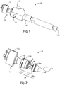
- reference numeral 10 denotes in its entirety an ejector for a refrigerating machine which, in an essentially traditional way, comprises:
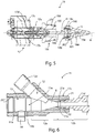
- a special feature of the ejector 10 in the present invention is that it comprises a connector element 18 which can be fixed or is fixed to the activating group 17 and to the nozzle 15 thereby forming a cartridge organ 19 that is autonomous relative to the main body 11; the ejector 10 comprising coupling means 20a, 20b able to fix and thus seal, in a removable way, the cartridge organ 19 to the main body 11.
- the connector element 18, according to present invention can be a separate part that is fixable to the activating group 17 and/or to the nozzle 15 or can be in a single piece with the activating group 17 and/or with the nozzle 15.
- an ejector 10 consists of two components, which are easy to assemble and disassemble, which are the main body of the ejector and the cartridge organ which comprises the nozzle, the closure member thereof and the activating group of the closure member.
- an autonomous product in fact enables a simpler mounting of the ejector 10, enabling first assembling the cartridge organ and subsequently installing it in the compartment 13 of the main body 11.
- the maintenance is also easier, enabling easily separating the cartridge organ and easily verifying the conformity of the closure member, the nozzle or the activating group.
- the activating group 17 preferably comprises a tubular jacket, advantageously obtained by drawing, in which the rotor of an electric stepper motor is housed, the stator of which is fixed externally of the tubular jacket.
- a screw-nut screw mechanism 17d preferably housed inside the tubular jacket 17a, connects the rotor 17b to the closure member 16, so that a rotation of the rotor is followed by a similar movement of the closure member 16 with respect to the hole 15a.
- the connector element 18 advantageously comprises:
- the connector element 18 is advantageously configured so that the connecting portion 18a has a predefined position with respect to the support portion 18b for guaranteeing a predefined geometric tolerance of alignment and coaxial attitude between the closure member 16 and the nozzle 15.
- the support portion 18b and the nozzle 15 comprise:
- the support portion 18b is advantageously discoidal with through-openings and a central seating which can be engaged by the closure member 16 so as to guide it with respect to the hole 15a.
- the support portion 18b can constructively be in a single piece with the joining portion 18c or can be fixable thereto and/or to the nozzle 15 by means of a threaded coupling.
- the connector element 18 is preferably configured so as to have a free passage which is open towards the mouth 14 and towards the hole 15a and can be crossed by refrigerant fluid originating from the mouth 14 and directed to the hole 15a of the nozzle (15).
- the activating group 17 is configured for moving the closure member 16 along an operating direction A along which the hole 15a of said nozzle 15 extends.
- the joining portion 18c comprises at least a bracket 21 which extends along the operating direction A, from the connecting portion 18a to the support portion 18b.
- the joining portion advantageously comprises two brackets 21, which are straight and positioned on opposite sides with respect to the stem 16b of the closure member 16.
- brackets 21 are advantageously located laterally to a central axis of the mouth 14, when the cartridge organ 19 is joined to the main body 11.
- the coupling means 20a, 20b advantageously comprise:
- the coupling means 20a, 20b preferably comprise centring parts provided on the main body 11 and on the cartridge organ 19 which are reciprocally combined and are configured so that when the cartridge organ 19 is assembled with the main body 11, the reciprocal position thereof is defined with a predefined tolerance both of form and of position and in general geometric.
- the external walls 18d and 18e are complementary to the internal walls 11 a and 11 b so as to define a centring constraint for the cartridge organ 19 with respect to the body of the ejector.
- seals are preferably included, preferably O-rings 100 interposed between the internal walls 11 a and 11 b and the external walls 18d and 18e, so as to guarantee the seal of the coupling of the cartridge organ 19 with the main body 11.
- the external wall 18d is preferably a part of the connecting portion 18a of the connector element 18 and is provided with a complementary threading 201 to a threading 202 made on the corresponding internal wall 11 a of the main body 11, so as to be able to couple the cartridge organ thereto by screwing.
- the threadings 201 and 202 are advantageously configured so that when the cartridge organ 19 is coupled to the main body 11 by screwing according to a predefined locking torque, the brackets 21 are lateral to the central axis of the mouth 14 and preferably lie on a perpendicular plane to the central axis so as to minimise the fluid-dynamic losses due to the passage of the refrigerant fluid from the mouth 14 to the nozzle 15.
- the main body 11 advantageously comprises:
- one of the components 11c and 11d preferably has a female connector 21 which can be coupled to a male connector 22 which is a part of the other of the components 11 c and 11 d.
- the connectors 21, 22 are configured so that, when coupled, the first part 12a and the second part 12b of said conduit 12 are aligned so as to respect a predefined geometric tolerance.
- the connectors 21 and 22 are cylindrical so as to define a centring constraint between the components 11c and 11d and are provided with threadings so as to be coupled to one another.
- the connectors 21 and 22 are advantageously fixed monolithically to one another, for example by brazing and/or by friction coupling.
- the conduit 12 comprises an operating section which consists in the second part 12b of the conduit 12 and a section of the first part 12a of said conduit 12, which extends from the seating 13a up to the second part 12b.
- This operating section extends from the seating 13a to the outlet opening 12d along a straight geometric axis which, when the ejector 10 is assembled, coincides with the operating direction A.
- the male connector 22 is preferably provided with a cylindrical collar 22a coaxial to said geometric axis and the female connector 21 is provided with a cylindrical opening 21 a able to receive as an insert the cylindrical collar 22a and coaxial with the geometric axis for defining a coaxial constraint between the portions of the operating section of the conduit 12 respectively defined in the first 11 c and the second component 11 d.
- the main body 11 is made up of components 11 c and 11 d, it is of simpler embodiment as each component can easily be made by lathing a piece of brass for example and then fixed to the other component, for example by brazing and/or friction coupling.
- the invention as it is conceived is susceptible to numerous modifications and variants, all falling within the scope of protection of the appended claims.
Landscapes
- Engineering & Computer Science (AREA)
- Physics & Mathematics (AREA)
- Mechanical Engineering (AREA)
- General Engineering & Computer Science (AREA)
- Thermal Sciences (AREA)
- Fluid Mechanics (AREA)
- Jet Pumps And Other Pumps (AREA)
- Filling Or Discharging Of Gas Storage Vessels (AREA)
Claims (10)
- Ejektor (10) für eine Kälteanlage, aufweisend:- einen Grundkörper (11), der von einer Leitung (12) für den Durchgang eines Kältemittelfluids durchquert wird und eine Kammer (13) hat, die eine Sitzfläche (13a), welche mit der Leitung (12) in Verbindung ist, und eine Mündung (14) für den Einlass des Kältemittelfluids aufweist;- eine Düse (15), die mit der Sitzfläche (13a) verbunden ist und eine Innenbohrung (15a) für den Durchgang des Kältemittelfluids hat;- ein Verschlusselement (16) mit einem Ende (16a), das in der Lage ist, sich mit der Bohrung (15a) zu verbinden, um die Bohrung (15a) zu verschließen;- eine Aktivierungsgruppe (17), die an das Verschlusselement (16) anschließbar und in der Lage ist, das Verschlusselement (16) in Bezug auf die Bohrung (15a) der Düse (15) zu verschieben, um die Bohrung (15a) mit dem Verschlusselement (16) für eine Regulierung des Durchsatzes des Kältemittelfluids einstellbar zuzumachen, das, in Gebrauch von der Mündung (14) her kommend, über die Düse (15) in die Leitung (12) des Grundkörpers (11) eingeleitet wird;
dadurch gekennzeichnet, dass er ein Verbinderelement (18) aufweist, das an der Aktivierungsgruppe (17) und an der Düse (15) befestigt werden kann oder befestigt ist, um zusammen damit ein Kartuschenorgan (19) zu bilden, das relativ zum Grundkörper (11) eigenständig ist;
wobei der Ejektor (10) Kopplungsmittel (20a, 20b) aufweist, die in der Lage sind, das Kartuschenorgan (19) am Grundkörper (11) so zu befestigen und abzudichten, dass es davon abgenommen werden kann. - Ejektor (10) nach Anspruch 1, dadurch gekennzeichnet, dass das Verbinderelement (18) aufweist:- einen Verbindungsabschnitt (18a), der in der Lage ist, sich mit der Aktivierungsgruppe (17) zu verbinden;- eine Halterungsabschnitt (18b), der in der Lage ist, das Verschlusselement (16) bezüglich der Düse (15) zentriert in Bezug auf die Bohrung (15a) zu führen;- einen Anschlussabschnitt (18c), der den Verbindungsabschnitt (18a) fest an den Halterungsabschnitt (18b) anschließt, um den Verbindungsabschnitt (18a) und den Halterungsabschnitt (18b) in einer vorbestimmten Relativposition zu halten.
- Ejektor (10) nach einem der vorhergehenden Ansprüche, dadurch gekennzeichnet, dass das Verbinderelement (18) so ausgelegt ist, dass es einen freien Durchgang hat, der zur Mündung (14) und zur Bohrung (15a) hin offen ist und von einem Kältemittelfluid durchquert werden kann, das von der Mündung (14) her kommt und zur Bohrung (15a) der Düse (15) gerichtet ist.
- Ejektor (10) nach Anspruch 3, dadurch gekennzeichnet, dass die Aktivierungsgruppe (17) dafür ausgelegt ist, das Verschlusselement (16) entlang einer Betätigungsrichtung (A) zur verschieben, entlang der sich die Bohrung (15a) der Düse (15) erstreckt; wobei das Verbinderelement (18) mindestens einen Halter (21) aufweist, der sich entlang der Betätigungsrichtung (A) vom Verbindungsabschnitt (18a) zum Halterungsabschnitt (18b) erstreckt.
- Ejektor (10) nach Anspruch 3, dadurch gekennzeichnet, dass der Anschlussabschnitt (18c) zwei Halter (21) aufweist, die geradlinig und in Bezug auf den Schaft (16b) des Verschlusselements (16) auf entgegengesetzten Seiten positioniert sind, wobei die Halter (21) seitlich relativ zu einer Mittelachse der Mündung (14) positioniert sind, wenn das Kartuschenorgan (19) an den Grundkörper (11) angefügt ist, um fluiddynamische Verluste des Kältemittelfluids zu minimieren, das in Gebrauch von der Mündung (14) zur Düse (15) strömt.
- Ejektor (10) nach einem der vorhergehenden Ansprüche, dadurch gekennzeichnet, dass die Kopplungsmittel (20a, 20b) Folgendes aufweisen:- ein erstes Kopplungsmittel (20a), das dafür ausgelegt ist, die Düse (15) an der Sitzfläche (13a) abzudichten und mit dieser zu verbinden;- ein zweites Kopplungsmittel (20b), das dafür ausgelegt ist, den Verbindungsabschnitt (18a) am Grundkörper (11) abzudichten und mit diesem zu verbinden, so dass sich die Mündung (14) in Gebrauch entlang der Betätigungsrichtung (A) in einer Position befindet, die zwischen dem Verbindungsabschnitt (18a) und der Düse (15) liegt.
- Ejektor (10) nach Anspruch 6, dadurch gekennzeichnet, dass die Kopplungsmittel (20a, 20b) Zentrierungsteile aufweisen, die am Grundkörper (11) und am Kartuschenorgan (19) vorgesehen sind, die zueinander komplementär und so ausgelegt sind, dass, wenn das Kartuschenorgan (19) mit dem Grundkörper (11) zusammengefügt ist, deren gegenseitige Position mit einer vorbestimmten Toleranz vorgegeben ist.
- Ejektor (10) nach einem der vorhergehenden Ansprüche, dadurch gekennzeichnet, dass der Grundkörper (11) aufweist:- ein erstes Bauteil (11c), in dem die Kammer (13) und ein erster Teil (12a) der Leitung (12) gebildet ist, der eine Einlassöffnung (12c) für das Kältemittelfluid aufweist;- ein zweites Bauteil (11d) mit einer abgedichteten Kopplung zum ersten Bauteil (11c), in dem ein zweiter Teil (12b) der Leitung (12) gebildet ist, und wobei der zweite Teil (12b) eine Auslassöffnung (12d) für das Kältemittelfluid aufweist.
- Ejektor (10) nach Anspruch 8, dadurch gekennzeichnet, dass eines der Bauteile (11c und 11d) ein Aufnahmeverbindungsstück (21) aufweist, das mit einem Einsteckverbindungsstück (22) verbunden werden kann, welches einen Teil des anderen der Bauteile (11c und 11d) darstellt; wobei die Verbindungsstücke (21, 22) so ausgelegt sind, dass sie bei Verbindung des ersten Teils (12a) mit dem zweiten Teil (12b) der Leitung (12) ausgerichtet sind, um vorbestimmte geometrische Toleranz einzuhalten.
- Ejektor (10) nach Anspruch 9, dadurch gekennzeichnet, dass die Leitung (12) ein Betriebsteilstück aufweist, das im zweiten Teil (12b) der Leitung (12) und einem Teilstück des ersten Teils (12a) der Leitung (12) besteht, das sich von der Sitzfläche (13a) für die Düse (15) bis zum zweiten Teil (12b) der Leitung (12) erstreckt; wobei sich das Betriebsteilstück von der Sitzfläche (13a) bis zur Auslassöffnung (12d) entlang einer geradlinigen geometrischen Achse erstreckt; wobei das Einsteckverbindungsstück (22) mit einem zylindrischen Bund (22a) versehen ist, der koaxial zur geometrischen Achse ist, und das Aufnahmeverbindungsstück (21) mit einer zylindrischen Öffnung (21a) versehen ist, die in der Lage ist, als Einsatz den zylindrischen Bund (22a) aufzunehmen, und koaxial zur geometrischen Achse ist, um eine koaxiale Zwangslage zwischen den Abschnitten des Betriebsabschnitts der Leitung (12) vorzugeben, die im ersten bzw. zweiten Bauteil (11d) gebildet sind.
Applications Claiming Priority (1)
| Application Number | Priority Date | Filing Date | Title |
|---|---|---|---|
| ITUA2016A002684A ITUA20162684A1 (it) | 2016-04-18 | 2016-04-18 | Eiettore per macchina frigorifera |
Publications (3)
| Publication Number | Publication Date |
|---|---|
| EP3236179A1 EP3236179A1 (de) | 2017-10-25 |
| EP3236179B1 true EP3236179B1 (de) | 2021-05-26 |
| EP3236179B2 EP3236179B2 (de) | 2024-08-07 |
Family
ID=56555589
Family Applications (1)
| Application Number | Title | Priority Date | Filing Date |
|---|---|---|---|
| EP17165647.3A Active EP3236179B2 (de) | 2016-04-18 | 2017-04-10 | Ejektor für eine kälteanlage |
Country Status (7)
| Country | Link |
|---|---|
| US (1) | US10900500B2 (de) |
| EP (1) | EP3236179B2 (de) |
| JP (1) | JP2017198209A (de) |
| CN (1) | CN107305073B (de) |
| CA (1) | CA2964588A1 (de) |
| DK (1) | DK3236179T4 (de) |
| IT (1) | ITUA20162684A1 (de) |
Families Citing this family (1)
| Publication number | Priority date | Publication date | Assignee | Title |
|---|---|---|---|---|
| CN110411051A (zh) * | 2018-04-27 | 2019-11-05 | 杭州三花研究院有限公司 | 热管理系统以及喷射器 |
Citations (5)
| Publication number | Priority date | Publication date | Assignee | Title |
|---|---|---|---|---|
| JP2006233807A (ja) | 2005-02-23 | 2006-09-07 | Denso Corp | エジェクタ |
| JP2008151017A (ja) | 2006-12-15 | 2008-07-03 | Denso Corp | エジェクタ装置およびその製造方法 |
| US20090311111A1 (en) | 2008-06-16 | 2009-12-17 | Denso Corporation | Ejector |
| RU2009147853A (ru) | 2009-12-22 | 2011-06-27 | Государственное образовательное учреждение высшего профессионального образования "Северо-Кавказский государственный технический ун | Регулируемый эжектор |
| WO2015116480A1 (en) | 2014-01-30 | 2015-08-06 | Carrier Corporation | Ejectors and methods of use |
Family Cites Families (8)
| Publication number | Priority date | Publication date | Assignee | Title |
|---|---|---|---|---|
| JP4273977B2 (ja) * | 2004-01-21 | 2009-06-03 | 株式会社デンソー | エジェクタサイクル |
| JP4069880B2 (ja) * | 2004-02-18 | 2008-04-02 | 株式会社デンソー | エジェクタ |
| JP4367168B2 (ja) * | 2004-02-20 | 2009-11-18 | 株式会社日本自動車部品総合研究所 | 流量可変ノズル |
| ITPD20050312A1 (it) * | 2005-10-20 | 2007-04-21 | Carel Spa | Struttura perfezionata di valvola per la regolazione della portata di fluidi in particolare frigoriferi |
| NO2691706T3 (de) * | 2011-06-27 | 2018-05-12 | ||
| WO2014094890A1 (en) * | 2012-12-21 | 2014-06-26 | Xerex Ab | Vacuum ejector nozzle with elliptical diverging section |
| JP5999050B2 (ja) * | 2013-08-29 | 2016-09-28 | 株式会社デンソー | エジェクタ式冷凍サイクルおよびエジェクタ |
| EP3099987B1 (de) * | 2014-01-30 | 2022-07-20 | Carrier Corporation | Ejektor und verfahren zur herstellung dafür |
-
2016
- 2016-04-18 IT ITUA2016A002684A patent/ITUA20162684A1/it unknown
-
2017
- 2017-04-10 EP EP17165647.3A patent/EP3236179B2/de active Active
- 2017-04-10 DK DK17165647.3T patent/DK3236179T4/da active
- 2017-04-13 CA CA2964588A patent/CA2964588A1/en not_active Abandoned
- 2017-04-17 JP JP2017081616A patent/JP2017198209A/ja active Pending
- 2017-04-18 CN CN201710253690.5A patent/CN107305073B/zh active Active
- 2017-04-18 US US15/489,797 patent/US10900500B2/en active Active
Patent Citations (5)
| Publication number | Priority date | Publication date | Assignee | Title |
|---|---|---|---|---|
| JP2006233807A (ja) | 2005-02-23 | 2006-09-07 | Denso Corp | エジェクタ |
| JP2008151017A (ja) | 2006-12-15 | 2008-07-03 | Denso Corp | エジェクタ装置およびその製造方法 |
| US20090311111A1 (en) | 2008-06-16 | 2009-12-17 | Denso Corporation | Ejector |
| RU2009147853A (ru) | 2009-12-22 | 2011-06-27 | Государственное образовательное учреждение высшего профессионального образования "Северо-Кавказский государственный технический ун | Регулируемый эжектор |
| WO2015116480A1 (en) | 2014-01-30 | 2015-08-06 | Carrier Corporation | Ejectors and methods of use |
Also Published As
| Publication number | Publication date |
|---|---|
| DK3236179T3 (da) | 2021-08-09 |
| US10900500B2 (en) | 2021-01-26 |
| CN107305073A (zh) | 2017-10-31 |
| JP2017198209A (ja) | 2017-11-02 |
| US20170298961A1 (en) | 2017-10-19 |
| EP3236179A1 (de) | 2017-10-25 |
| CA2964588A1 (en) | 2017-10-18 |
| EP3236179B2 (de) | 2024-08-07 |
| CN107305073B (zh) | 2021-07-13 |
| ITUA20162684A1 (it) | 2017-10-18 |
| DK3236179T4 (da) | 2024-08-19 |
Similar Documents
| Publication | Publication Date | Title |
|---|---|---|
| US11506315B2 (en) | Hose connector assembly, use of a hose connector assembly, and sanitary fitting | |
| KR102454733B1 (ko) | 전자 팽창 밸브 | |
| CN105276199B (zh) | 电动阀 | |
| JP6591478B2 (ja) | 制御弁およびその製造方法 | |
| EP3219858B1 (de) | Temperaturregelnder hahn | |
| EP3236179B2 (de) | Ejektor für eine kälteanlage | |
| US20170227131A1 (en) | Control or shutoff valve | |
| JP5982659B2 (ja) | 流量調節バルブのダイヤフラム弁体 | |
| JP6045368B2 (ja) | 流体機器ユニット | |
| CN109296805A (zh) | 电动阀以及冷冻循环系统 | |
| JP2013204725A5 (de) | ||
| US11920718B2 (en) | Additive manufactured liquid manifold with orifice | |
| CN100529483C (zh) | 截流阀、具有截流阀的成套器具以及膨胀阀 | |
| CN113339607A (zh) | 用于连接流体通路的组合装置 | |
| JP7190775B2 (ja) | 電磁弁一体型膨張弁 | |
| EP3892898A1 (de) | Ventilvorrichtung | |
| CN114517839B (zh) | 卫生出口单元和用于安装和/或拆卸其的方法 | |
| CN203098901U (zh) | 阀针组件以及包括该阀针组件的电子膨胀阀 | |
| JP2001032343A (ja) | シャワー水栓装置 | |
| CN204239809U (zh) | 水龙头组件 | |
| CN207945332U (zh) | 一种用于水龙头的阀体组件 | |
| CN120251716A (zh) | 一种旋转式开关机构及阀 | |
| CN118664309A (zh) | 一种喷射器的制造方法 | |
| US10323664B2 (en) | Orifice module for flow switch system | |
| CN201731200U (zh) | 水管接头 |
Legal Events
| Date | Code | Title | Description |
|---|---|---|---|
| PUAI | Public reference made under article 153(3) epc to a published international application that has entered the european phase |
Free format text: ORIGINAL CODE: 0009012 |
|
| STAA | Information on the status of an ep patent application or granted ep patent |
Free format text: STATUS: THE APPLICATION HAS BEEN PUBLISHED |
|
| AK | Designated contracting states |
Kind code of ref document: A1 Designated state(s): AL AT BE BG CH CY CZ DE DK EE ES FI FR GB GR HR HU IE IS IT LI LT LU LV MC MK MT NL NO PL PT RO RS SE SI SK SM TR |
|
| AX | Request for extension of the european patent |
Extension state: BA ME |
|
| STAA | Information on the status of an ep patent application or granted ep patent |
Free format text: STATUS: REQUEST FOR EXAMINATION WAS MADE |
|
| 17P | Request for examination filed |
Effective date: 20180424 |
|
| RBV | Designated contracting states (corrected) |
Designated state(s): AL AT BE BG CH CY CZ DE DK EE ES FI FR GB GR HR HU IE IS IT LI LT LU LV MC MK MT NL NO PL PT RO RS SE SI SK SM TR |
|
| STAA | Information on the status of an ep patent application or granted ep patent |
Free format text: STATUS: EXAMINATION IS IN PROGRESS |
|
| 17Q | First examination report despatched |
Effective date: 20200529 |
|
| GRAP | Despatch of communication of intention to grant a patent |
Free format text: ORIGINAL CODE: EPIDOSNIGR1 |
|
| STAA | Information on the status of an ep patent application or granted ep patent |
Free format text: STATUS: GRANT OF PATENT IS INTENDED |
|
| INTG | Intention to grant announced |
Effective date: 20201109 |
|
| GRAS | Grant fee paid |
Free format text: ORIGINAL CODE: EPIDOSNIGR3 |
|
| GRAA | (expected) grant |
Free format text: ORIGINAL CODE: 0009210 |
|
| STAA | Information on the status of an ep patent application or granted ep patent |
Free format text: STATUS: THE PATENT HAS BEEN GRANTED |
|
| AK | Designated contracting states |
Kind code of ref document: B1 Designated state(s): AL AT BE BG CH CY CZ DE DK EE ES FI FR GB GR HR HU IE IS IT LI LT LU LV MC MK MT NL NO PL PT RO RS SE SI SK SM TR |
|
| REG | Reference to a national code |
Ref country code: GB Ref legal event code: FG4D |
|
| REG | Reference to a national code |
Ref country code: CH Ref legal event code: EP |
|
| REG | Reference to a national code |
Ref country code: AT Ref legal event code: REF Ref document number: 1396626 Country of ref document: AT Kind code of ref document: T Effective date: 20210615 |
|
| REG | Reference to a national code |
Ref country code: DE Ref legal event code: R096 Ref document number: 602017039119 Country of ref document: DE |
|
| REG | Reference to a national code |
Ref country code: IE Ref legal event code: FG4D |
|
| REG | Reference to a national code |
Ref country code: DK Ref legal event code: T3 Effective date: 20210804 |
|
| REG | Reference to a national code |
Ref country code: LT Ref legal event code: MG9D |
|
| REG | Reference to a national code |
Ref country code: AT Ref legal event code: MK05 Ref document number: 1396626 Country of ref document: AT Kind code of ref document: T Effective date: 20210526 |
|
| PG25 | Lapsed in a contracting state [announced via postgrant information from national office to epo] |
Ref country code: HR Free format text: LAPSE BECAUSE OF FAILURE TO SUBMIT A TRANSLATION OF THE DESCRIPTION OR TO PAY THE FEE WITHIN THE PRESCRIBED TIME-LIMIT Effective date: 20210526 Ref country code: AT Free format text: LAPSE BECAUSE OF FAILURE TO SUBMIT A TRANSLATION OF THE DESCRIPTION OR TO PAY THE FEE WITHIN THE PRESCRIBED TIME-LIMIT Effective date: 20210526 Ref country code: BG Free format text: LAPSE BECAUSE OF FAILURE TO SUBMIT A TRANSLATION OF THE DESCRIPTION OR TO PAY THE FEE WITHIN THE PRESCRIBED TIME-LIMIT Effective date: 20210826 Ref country code: FI Free format text: LAPSE BECAUSE OF FAILURE TO SUBMIT A TRANSLATION OF THE DESCRIPTION OR TO PAY THE FEE WITHIN THE PRESCRIBED TIME-LIMIT Effective date: 20210526 Ref country code: LT Free format text: LAPSE BECAUSE OF FAILURE TO SUBMIT A TRANSLATION OF THE DESCRIPTION OR TO PAY THE FEE WITHIN THE PRESCRIBED TIME-LIMIT Effective date: 20210526 |
|
| REG | Reference to a national code |
Ref country code: NL Ref legal event code: MP Effective date: 20210526 |
|
| PG25 | Lapsed in a contracting state [announced via postgrant information from national office to epo] |
Ref country code: GR Free format text: LAPSE BECAUSE OF FAILURE TO SUBMIT A TRANSLATION OF THE DESCRIPTION OR TO PAY THE FEE WITHIN THE PRESCRIBED TIME-LIMIT Effective date: 20210827 Ref country code: IS Free format text: LAPSE BECAUSE OF FAILURE TO SUBMIT A TRANSLATION OF THE DESCRIPTION OR TO PAY THE FEE WITHIN THE PRESCRIBED TIME-LIMIT Effective date: 20210926 Ref country code: LV Free format text: LAPSE BECAUSE OF FAILURE TO SUBMIT A TRANSLATION OF THE DESCRIPTION OR TO PAY THE FEE WITHIN THE PRESCRIBED TIME-LIMIT Effective date: 20210526 Ref country code: SE Free format text: LAPSE BECAUSE OF FAILURE TO SUBMIT A TRANSLATION OF THE DESCRIPTION OR TO PAY THE FEE WITHIN THE PRESCRIBED TIME-LIMIT Effective date: 20210526 Ref country code: RS Free format text: LAPSE BECAUSE OF FAILURE TO SUBMIT A TRANSLATION OF THE DESCRIPTION OR TO PAY THE FEE WITHIN THE PRESCRIBED TIME-LIMIT Effective date: 20210526 Ref country code: PT Free format text: LAPSE BECAUSE OF FAILURE TO SUBMIT A TRANSLATION OF THE DESCRIPTION OR TO PAY THE FEE WITHIN THE PRESCRIBED TIME-LIMIT Effective date: 20210927 Ref country code: NO Free format text: LAPSE BECAUSE OF FAILURE TO SUBMIT A TRANSLATION OF THE DESCRIPTION OR TO PAY THE FEE WITHIN THE PRESCRIBED TIME-LIMIT Effective date: 20210826 Ref country code: PL Free format text: LAPSE BECAUSE OF FAILURE TO SUBMIT A TRANSLATION OF THE DESCRIPTION OR TO PAY THE FEE WITHIN THE PRESCRIBED TIME-LIMIT Effective date: 20210526 |
|
| PG25 | Lapsed in a contracting state [announced via postgrant information from national office to epo] |
Ref country code: NL Free format text: LAPSE BECAUSE OF FAILURE TO SUBMIT A TRANSLATION OF THE DESCRIPTION OR TO PAY THE FEE WITHIN THE PRESCRIBED TIME-LIMIT Effective date: 20210526 |
|
| PG25 | Lapsed in a contracting state [announced via postgrant information from national office to epo] |
Ref country code: SK Free format text: LAPSE BECAUSE OF FAILURE TO SUBMIT A TRANSLATION OF THE DESCRIPTION OR TO PAY THE FEE WITHIN THE PRESCRIBED TIME-LIMIT Effective date: 20210526 Ref country code: SM Free format text: LAPSE BECAUSE OF FAILURE TO SUBMIT A TRANSLATION OF THE DESCRIPTION OR TO PAY THE FEE WITHIN THE PRESCRIBED TIME-LIMIT Effective date: 20210526 Ref country code: CZ Free format text: LAPSE BECAUSE OF FAILURE TO SUBMIT A TRANSLATION OF THE DESCRIPTION OR TO PAY THE FEE WITHIN THE PRESCRIBED TIME-LIMIT Effective date: 20210526 Ref country code: EE Free format text: LAPSE BECAUSE OF FAILURE TO SUBMIT A TRANSLATION OF THE DESCRIPTION OR TO PAY THE FEE WITHIN THE PRESCRIBED TIME-LIMIT Effective date: 20210526 Ref country code: RO Free format text: LAPSE BECAUSE OF FAILURE TO SUBMIT A TRANSLATION OF THE DESCRIPTION OR TO PAY THE FEE WITHIN THE PRESCRIBED TIME-LIMIT Effective date: 20210526 Ref country code: ES Free format text: LAPSE BECAUSE OF FAILURE TO SUBMIT A TRANSLATION OF THE DESCRIPTION OR TO PAY THE FEE WITHIN THE PRESCRIBED TIME-LIMIT Effective date: 20210526 |
|
| REG | Reference to a national code |
Ref country code: DE Ref legal event code: R026 Ref document number: 602017039119 Country of ref document: DE |
|
| PLBI | Opposition filed |
Free format text: ORIGINAL CODE: 0009260 |
|
| PLAX | Notice of opposition and request to file observation + time limit sent |
Free format text: ORIGINAL CODE: EPIDOSNOBS2 |
|
| 26 | Opposition filed |
Opponent name: BITZER KUEHLMASCHINENBAU GMBH Effective date: 20220224 |
|
| PG25 | Lapsed in a contracting state [announced via postgrant information from national office to epo] |
Ref country code: IS Free format text: LAPSE BECAUSE OF FAILURE TO SUBMIT A TRANSLATION OF THE DESCRIPTION OR TO PAY THE FEE WITHIN THE PRESCRIBED TIME-LIMIT Effective date: 20210926 Ref country code: AL Free format text: LAPSE BECAUSE OF FAILURE TO SUBMIT A TRANSLATION OF THE DESCRIPTION OR TO PAY THE FEE WITHIN THE PRESCRIBED TIME-LIMIT Effective date: 20210526 |
|
| PLBB | Reply of patent proprietor to notice(s) of opposition received |
Free format text: ORIGINAL CODE: EPIDOSNOBS3 |
|
| REG | Reference to a national code |
Ref country code: CH Ref legal event code: PL |
|
| REG | Reference to a national code |
Ref country code: BE Ref legal event code: MM Effective date: 20220430 |
|
| PG25 | Lapsed in a contracting state [announced via postgrant information from national office to epo] |
Ref country code: MC Free format text: LAPSE BECAUSE OF FAILURE TO SUBMIT A TRANSLATION OF THE DESCRIPTION OR TO PAY THE FEE WITHIN THE PRESCRIBED TIME-LIMIT Effective date: 20210526 Ref country code: LU Free format text: LAPSE BECAUSE OF NON-PAYMENT OF DUE FEES Effective date: 20220410 Ref country code: LI Free format text: LAPSE BECAUSE OF NON-PAYMENT OF DUE FEES Effective date: 20220430 Ref country code: CH Free format text: LAPSE BECAUSE OF NON-PAYMENT OF DUE FEES Effective date: 20220430 |
|
| PG25 | Lapsed in a contracting state [announced via postgrant information from national office to epo] |
Ref country code: BE Free format text: LAPSE BECAUSE OF NON-PAYMENT OF DUE FEES Effective date: 20220430 |
|
| PG25 | Lapsed in a contracting state [announced via postgrant information from national office to epo] |
Ref country code: IE Free format text: LAPSE BECAUSE OF NON-PAYMENT OF DUE FEES Effective date: 20220410 |
|
| PG25 | Lapsed in a contracting state [announced via postgrant information from national office to epo] |
Ref country code: HU Free format text: LAPSE BECAUSE OF FAILURE TO SUBMIT A TRANSLATION OF THE DESCRIPTION OR TO PAY THE FEE WITHIN THE PRESCRIBED TIME-LIMIT; INVALID AB INITIO Effective date: 20170410 |
|
| PG25 | Lapsed in a contracting state [announced via postgrant information from national office to epo] |
Ref country code: MK Free format text: LAPSE BECAUSE OF FAILURE TO SUBMIT A TRANSLATION OF THE DESCRIPTION OR TO PAY THE FEE WITHIN THE PRESCRIBED TIME-LIMIT Effective date: 20210526 Ref country code: CY Free format text: LAPSE BECAUSE OF FAILURE TO SUBMIT A TRANSLATION OF THE DESCRIPTION OR TO PAY THE FEE WITHIN THE PRESCRIBED TIME-LIMIT Effective date: 20210526 |
|
| PG25 | Lapsed in a contracting state [announced via postgrant information from national office to epo] |
Ref country code: TR Free format text: LAPSE BECAUSE OF FAILURE TO SUBMIT A TRANSLATION OF THE DESCRIPTION OR TO PAY THE FEE WITHIN THE PRESCRIBED TIME-LIMIT Effective date: 20210526 |
|
| PUAH | Patent maintained in amended form |
Free format text: ORIGINAL CODE: 0009272 |
|
| STAA | Information on the status of an ep patent application or granted ep patent |
Free format text: STATUS: PATENT MAINTAINED AS AMENDED |
|
| 27A | Patent maintained in amended form |
Effective date: 20240807 |
|
| AK | Designated contracting states |
Kind code of ref document: B2 Designated state(s): AL AT BE BG CH CY CZ DE DK EE ES FI FR GB GR HR HU IE IS IT LI LT LU LV MC MK MT NL NO PL PT RO RS SE SI SK SM TR |
|
| REG | Reference to a national code |
Ref country code: DE Ref legal event code: R102 Ref document number: 602017039119 Country of ref document: DE |
|
| REG | Reference to a national code |
Ref country code: DK Ref legal event code: T4 Effective date: 20240813 |
|
| PG25 | Lapsed in a contracting state [announced via postgrant information from national office to epo] |
Ref country code: MT Free format text: LAPSE BECAUSE OF FAILURE TO SUBMIT A TRANSLATION OF THE DESCRIPTION OR TO PAY THE FEE WITHIN THE PRESCRIBED TIME-LIMIT Effective date: 20210526 |
|
| PGFP | Annual fee paid to national office [announced via postgrant information from national office to epo] |
Ref country code: DE Payment date: 20250422 Year of fee payment: 9 |
|
| PGFP | Annual fee paid to national office [announced via postgrant information from national office to epo] |
Ref country code: GB Payment date: 20250423 Year of fee payment: 9 Ref country code: DK Payment date: 20250429 Year of fee payment: 9 |
|
| PGFP | Annual fee paid to national office [announced via postgrant information from national office to epo] |
Ref country code: IT Payment date: 20250402 Year of fee payment: 9 |
|
| PGFP | Annual fee paid to national office [announced via postgrant information from national office to epo] |
Ref country code: FR Payment date: 20250425 Year of fee payment: 9 |