EP3235667A1 - Link structure for a motor vehicle, in particular trailing arm structure - Google Patents
Link structure for a motor vehicle, in particular trailing arm structure Download PDFInfo
- Publication number
- EP3235667A1 EP3235667A1 EP17167453.4A EP17167453A EP3235667A1 EP 3235667 A1 EP3235667 A1 EP 3235667A1 EP 17167453 A EP17167453 A EP 17167453A EP 3235667 A1 EP3235667 A1 EP 3235667A1
- Authority
- EP
- European Patent Office
- Prior art keywords
- coupling element
- construction
- bearing
- handlebar construction
- handlebar
- Prior art date
- Legal status (The legal status is an assumption and is not a legal conclusion. Google has not performed a legal analysis and makes no representation as to the accuracy of the status listed.)
- Granted
Links
- 230000008878 coupling Effects 0.000 claims abstract description 69
- 238000010168 coupling process Methods 0.000 claims abstract description 69
- 238000005859 coupling reaction Methods 0.000 claims abstract description 69
- 238000010276 construction Methods 0.000 claims abstract description 55
- 239000002131 composite material Substances 0.000 claims description 10
- 239000004033 plastic Substances 0.000 claims description 8
- 229920003023 plastic Polymers 0.000 claims description 8
- 229920002430 Fibre-reinforced plastic Polymers 0.000 claims description 7
- 239000011151 fibre-reinforced plastic Substances 0.000 claims description 7
- 239000000853 adhesive Substances 0.000 claims description 4
- 230000001070 adhesive effect Effects 0.000 claims description 4
- 229910052782 aluminium Inorganic materials 0.000 claims description 4
- XAGFODPZIPBFFR-UHFFFAOYSA-N aluminium Chemical compound [Al] XAGFODPZIPBFFR-UHFFFAOYSA-N 0.000 claims description 4
- 229910052751 metal Inorganic materials 0.000 claims description 4
- 239000002184 metal Substances 0.000 claims description 4
- 239000007769 metal material Substances 0.000 claims description 4
- 238000003801 milling Methods 0.000 claims description 4
- 229910000838 Al alloy Inorganic materials 0.000 claims description 3
- 238000004519 manufacturing process Methods 0.000 description 4
- 239000004918 carbon fiber reinforced polymer Substances 0.000 description 3
- 238000011161 development Methods 0.000 description 2
- 230000018109 developmental process Effects 0.000 description 2
- 239000011152 fibreglass Substances 0.000 description 2
- 230000006835 compression Effects 0.000 description 1
- 238000007906 compression Methods 0.000 description 1
- 230000001419 dependent effect Effects 0.000 description 1
- 239000000835 fiber Substances 0.000 description 1
- 238000000034 method Methods 0.000 description 1
- 238000012986 modification Methods 0.000 description 1
- 230000004048 modification Effects 0.000 description 1
Images
Classifications
-
- B—PERFORMING OPERATIONS; TRANSPORTING
- B60—VEHICLES IN GENERAL
- B60G—VEHICLE SUSPENSION ARRANGEMENTS
- B60G7/00—Pivoted suspension arms; Accessories thereof
- B60G7/001—Suspension arms, e.g. constructional features
-
- B—PERFORMING OPERATIONS; TRANSPORTING
- B60—VEHICLES IN GENERAL
- B60G—VEHICLE SUSPENSION ARRANGEMENTS
- B60G2206/00—Indexing codes related to the manufacturing of suspensions: constructional features, the materials used, procedures or tools
- B60G2206/01—Constructional features of suspension elements, e.g. arms, dampers, springs
- B60G2206/012—Hollow or tubular elements
-
- B—PERFORMING OPERATIONS; TRANSPORTING
- B60—VEHICLES IN GENERAL
- B60G—VEHICLE SUSPENSION ARRANGEMENTS
- B60G2206/00—Indexing codes related to the manufacturing of suspensions: constructional features, the materials used, procedures or tools
- B60G2206/01—Constructional features of suspension elements, e.g. arms, dampers, springs
- B60G2206/10—Constructional features of arms
- B60G2206/11—Constructional features of arms the arm being a radius or track or torque or steering rod or stabiliser end link
-
- B—PERFORMING OPERATIONS; TRANSPORTING
- B60—VEHICLES IN GENERAL
- B60G—VEHICLE SUSPENSION ARRANGEMENTS
- B60G2206/00—Indexing codes related to the manufacturing of suspensions: constructional features, the materials used, procedures or tools
- B60G2206/01—Constructional features of suspension elements, e.g. arms, dampers, springs
- B60G2206/10—Constructional features of arms
- B60G2206/16—Constructional features of arms the arm having a U profile and/or made of a plate
-
- B—PERFORMING OPERATIONS; TRANSPORTING
- B60—VEHICLES IN GENERAL
- B60G—VEHICLE SUSPENSION ARRANGEMENTS
- B60G2206/00—Indexing codes related to the manufacturing of suspensions: constructional features, the materials used, procedures or tools
- B60G2206/01—Constructional features of suspension elements, e.g. arms, dampers, springs
- B60G2206/70—Materials used in suspensions
- B60G2206/71—Light weight materials
- B60G2206/7101—Fiber-reinforced plastics [FRP]
-
- B—PERFORMING OPERATIONS; TRANSPORTING
- B60—VEHICLES IN GENERAL
- B60G—VEHICLE SUSPENSION ARRANGEMENTS
- B60G2206/00—Indexing codes related to the manufacturing of suspensions: constructional features, the materials used, procedures or tools
- B60G2206/01—Constructional features of suspension elements, e.g. arms, dampers, springs
- B60G2206/70—Materials used in suspensions
- B60G2206/71—Light weight materials
- B60G2206/7102—Aluminium alloys
Definitions
- the invention relates to a handlebar construction for a motor vehicle, preferably a trailing arm construction.
- Trailing arm designs for motor vehicles are known in the prior art in a variety of embodiments, for this purpose by way of example to the documents DE 10 2007 022 283 A1 and DE 10 2014 211 051 A1 can be referenced. From the latter document is already known to form leaf spring trailing arm made of fiber-reinforced plastic.
- An object of the invention is to provide an alternative and / or improved handlebar construction for a motor vehicle.
- the invention provides a handlebar construction for a motor vehicle, z.
- a motor vehicle z.
- a passenger car or a commercial vehicle in particular a truck or a bus.
- the link construction is preferably designed as a trailing arm construction.
- the linkage construction comprises a first bearing section (eg bearing seat), a second bearing section (eg bearing seat) and a coupling element which extends between the first bearing section and the second bearing section and for the purpose of indirectly or directly connecting the first bearing element and the second bearing element is used.
- the handlebar construction is characterized in particular by the fact that at least one slot is formed in the connecting region for connecting the first bearing section and the coupling element, whereby in particular a manufacturing tolerance compensation is made possible, expedient in the circumferential direction of the coupling element.
- the link construction is characterized in particular in that the link construction is designed in a differential construction, preferably the first bearing section and / or the second bearing section made of a metallic material (eg aluminum or an aluminum alloy). is formed and the coupling element is formed from a fiber-plastic composite (eg., Fiber-reinforced plastic, in particular CFRP or GRP).
- the handlebar construction preferably allows a compensation of manufacturing tolerances, expedient in the circumferential direction of the coupling element, a variable, adaptable to the specific application component length, the use of inexpensive standard elastomeric bearings, high weight savings, high rigidity / strength and / or use of the handlebar construction as a train - and / or compression strut.
- a clamp for the purpose of appropriate fixing of the first bearing section is arranged on the coupling element.
- the first bearing portion and the coupling element may, for. B. be pushed towards each other and / or overlap in sections, expediently in the connection area for connecting the first bearing portion and the coupling element.
- the first bearing section may in particular comprise a partial section and the partial section may preferably extend into the coupling element.
- the section is preferably formed hollow profile, z. B. round tube-shaped, rectangular hollow profile, etc.
- the slot is preferably formed in the coupling element and / or extends inwardly from an end face of the coupling element.
- the slot extends substantially parallel to the longitudinal extent of the coupling element or extends obliquely to the longitudinal extent of the coupling element.
- the clamp can z. B. serve to fix the adhesive and / or press connection.
- connection region for connecting the first bearing section and the coupling element comprises in particular an axial end and / or end side section of the coupling element.
- the coupling element can, for. B. from a fiber-reinforced plastic composite (eg., Fiber-reinforced plastic, eg., GFK or CFK) may be formed.
- a fiber-reinforced plastic composite eg., Fiber-reinforced plastic, eg., GFK or CFK
- the first bearing portion and / or the second bearing portion may be formed of metallic material, preferably of aluminum or an aluminum alloy. Thereby, the differential construction can be formed.
- the coupling element is preferably produced by pultrusion (pultrusion method).
- the clamp may be formed from a fiber-plastic composite (eg fiber-reinforced plastic), be designed as a milling component or be designed as a sheet-metal component.
- a fiber-plastic composite eg fiber-reinforced plastic
- the first storage section can, for. B. have a substantially eye-shaped (in particular annular) portion and / or z. B. wear an elastomeric bearing, preferably by means of the eye-shaped portion.
- the coupling element is preferably designed as a hollow profile element (eg round hollow profile element or rectangular hollow profile element).
- the slot can pierce the wall of the hollow profile element expedient.
- the slot bottom of the slot that is to say an axial end section of the slot, can be expediently rounded, drop-shaped and / or essentially circular or semicircular.
- the fiber plastic composite can z. B. comprise a longitudinally reinforced, substantially quasi-isotropic laminate.
- connection region for connecting the first bearing portion and the coupling element may expediently an expansion screw z. B. be arranged to reduce subsidence.
- connection region for connecting the second bearing section and the coupling element may also be formed at least one slot.
- first bearing section and the second bearing section and in particular their mounting to the coupling element are preferably of identical construction, so that the disclosure made herein for the first bearing section and its mounting to the coupling element applies accordingly to the second bearing section and its mounting to the coupling element and also claimable ,
- the at least one slot can in particular form a type of slot-ring structure, which may be substantially annular, but need not necessarily be annular.
- the at least one slot in the assembled state in which the first bearing section is mounted on the coupling element (eg pressed, glued and / or clamp-fixed), can be expediently opened at least in sections, so that the side walls of the slot at least partially spaced from each other, or at least partially closed, so that contact the side walls at least in sections.
- the coupling element is preferably designed as a hollow profile element, preferably as a round hollow profile element.
- the invention is not limited to a handlebar construction as disclosed herein, but also includes a motor vehicle having at least one such handlebar construction.
- the motor vehicle can, for. As a passenger car or a commercial vehicle, in particular a truck or a bus to be.
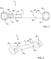
- FIG. 1 shows a partially sectioned side view of a handlebar construction 1 for a motor vehicle, in particular a trailing arm 1.
- the link construction 1 comprises a first bearing section 2a, a second bearing section 2a and a coupling element 3 designed as a round hollow profile, which extends between the first bearing section 2a and the second bearing section 2b and serves to connect the first bearing section 2a and the second bearing section 2b.
- connection region 4a for connecting the first bearing section 2a and the coupling element 3 at least one slot 5a is formed, which enables a manufacturing tolerance compensation in the circumferential direction of the coupling element 3.
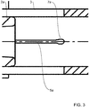
- the slot 5a is formed in the coupling element 3 and extends inwardly from an end face of the coupling element 3 substantially parallel to the longitudinal extent of the coupling element 3.
- a slot bottom 7a of the slot 5a is suitably rounded, z. B. substantially drop or semicircular.
- connection region 4 a comprises an axial end / end side section of the coupling element 3.
- the first bearing section 2a and the coupling element 3 are pushed onto one another in the connection area 4a and overlap in sections.
- the first bearing section 2 a extends with a hollow profile-shaped partial section 2 into the coupling element 3.
- the first bearing portion 2a also includes a substantially loop-shaped portion 2y for supporting an elastomeric bearing.
- the first bearing section 2a and the coupling element 3 are expediently glued together and pressed.
- a clamp 6a, in particular clamp 6a, in the connection region 4a serves to fix the adhesive and press connection.
- the clamp 6a may be formed from fiber-plastic composite, be formed as a milling component or sheet metal component.
- the handlebar construction 1 is designed in differential construction.
- the first bearing portion 2a and the second bearing portion 2b made of a metallic material, suitably aluminum, formed while the coupling element 3 is formed of a fiber-plastic composite, suitably a fiber-reinforced plastic, for.
- GFRP glass fiber reinforced plastic
- CFRP carbon fiber reinforced plastic
- the coupling element 3 is preferably produced by pultrusion.
- FIG. 1 right part of the handlebar construction 1 is designed substantially identical to that of the in FIG. 1 left part of the handlebar construction 1, so that previously made description applies mutatis mutandis to the right part of the handlebar construction 1.
- connection region 4b for connecting the second bearing section 2b and the coupling element 3 at least one slot 5b is likewise formed, which compensates for a manufacturing tolerance in the circumferential direction of the coupling element 3 allows.
- the slit 5b is likewise formed in the coupling element 3 and extends inwards from the other end face of the coupling element 3 substantially parallel to the longitudinal extension of the coupling element 3.
- a slot bottom 7b of the slot 5b is suitably rounded, z. B. substantially drop or semicircular.
- connection region 4b comprises, in particular, the other axial end / end side section of the coupling element 3.
- the second bearing section 2b and the coupling element 3 are pushed towards one another in the overlapping region 4b and overlap in sections.
- the second bearing portion 2b extends with a hollow profile-shaped portion into the coupling element 3 inside.
- the second bearing portion 2b also includes a substantially loop-shaped portion 2z for supporting an elastomeric bearing.
- the second bearing portion 2b and the coupling element 3 are also suitably glued together and pressed.
- a clamp 6b, in particular clamp 6b, in the connection area 4b serves to fix the adhesive and press connection.
- the clamp 6b may be formed from a fiber-plastic composite, be formed as a milling component or sheet metal component.
- FIG. 2 shows a perspective view of the handlebar construction 1 of FIG. 1 , but in contrast to FIG. 1 with elastomeric bearings received in the bearing sections 2a and 2b.
- FIG. 3 shows a detailed view of the slot 5a.
- the slot bottom 7a of the slot 5a is formed substantially drop-shaped.
Landscapes
- Engineering & Computer Science (AREA)
- Mechanical Engineering (AREA)
- Steering Devices For Bicycles And Motorcycles (AREA)
- Vehicle Body Suspensions (AREA)
Abstract
Die Erfindung betrifft eine Lenkerkonstruktion (1) für ein Kraftfahrzeug, vorzugsweise Längslenkerkonstruktion (1), mit einem ersten Lagerabschnitt (2a), einem zweiten Lagerabschnitt (2b) und einem Kopplungselement (3), das sich zwischen dem ersten Lagerabschnitt (2a) und dem zweiten Lagerabschnitt (2b) erstreckt und zur Verbindung des ersten Lagerabschnitts (2a) und des zweiten Lagerabschnitts (2b) dient. Die Lenkerkonstruktion (1) zeichnet sich insbesondere dadurch aus, dass im Verbindungsbereich (4a) zur Verbindung des ersten Lagerabschnitts (2a) und des Kopplungselements (3) zumindest ein Schlitz (5a) ausgebildet ist, und/oder die Lenkerkonstruktion (1) in Differentialbauweise ausgebildet istThe invention relates to a handlebar construction (1) for a motor vehicle, preferably trailing arm construction (1), comprising a first bearing section (2a), a second bearing section (2b) and a coupling element (3) located between the first bearing section (2a) and the first bearing section (2a) extends second bearing portion (2b) and for connecting the first bearing portion (2a) and the second bearing portion (2b) is used. The link construction (1) is characterized in particular in that at least one slot (5a) is formed in the connecting region (4a) for connecting the first bearing section (2a) and the coupling element (3), and / or the link construction (1) in differential construction is trained
Description
Die Erfindung betrifft eine Lenkerkonstruktion für ein Kraftfahrzeug, vorzugsweise eine Längslenkerkonstruktion.The invention relates to a handlebar construction for a motor vehicle, preferably a trailing arm construction.
Längslenkerkonstruktionen für Kraftfahrzeuge sind im Stand der Technik in den unterschiedlichsten Ausführungsformen bekannt, wobei hierzu beispielhaft auf die Dokumente
Eine Aufgabe der Erfindung ist es, eine alternative und/oder verbesserte Lenkerkonstruktion für ein Kraftfahrzeug zu schaffen.An object of the invention is to provide an alternative and / or improved handlebar construction for a motor vehicle.
Diese Aufgabe kann mit den Merkmalen des Hauptanspruchs gelöst werden. Vorteilhafte Weiterbildungen der Erfindung können den Unteransprüchen und der folgenden Beschreibung bevorzugter Ausführungsformen der Erfindung entnommen werden.This object can be achieved with the features of the main claim. Advantageous developments of the invention can be taken from the subclaims and the following description of preferred embodiments of the invention.
Die Erfindung schafft eine Lenkerkonstruktion für ein Kraftfahrzeug, z. B. einen Personenkraftwagen oder ein Nutzfahrzeug, insbesondere ein Lastkraftwagen oder ein Omnibus.The invention provides a handlebar construction for a motor vehicle, z. As a passenger car or a commercial vehicle, in particular a truck or a bus.
Die Lenkerkonstruktion ist vorzugsweise als Längslenkerkonstruktion ausgeführt.The link construction is preferably designed as a trailing arm construction.
Die Lenkerkonstruktion umfasst einen ersten Lagerabschnitt (z. B. Lageraufnahme), einen zweiten Lagerabschnitt (z. B. Lageraufnahme) und ein Kopplungselement, das sich zwischen dem ersten Lagerabschnitt und dem zweiten Lagerabschnitt erstreckt und zur zweckmäßig mittelbaren oder unmittelbaren Verbindung des ersten Lagerelements und des zweiten Lagerelements dient.The linkage construction comprises a first bearing section (eg bearing seat), a second bearing section (eg bearing seat) and a coupling element which extends between the first bearing section and the second bearing section and for the purpose of indirectly or directly connecting the first bearing element and the second bearing element is used.
Die Lenkerkonstruktion zeichnet sich insbesondere dadurch aus, dass im Verbindungsbereich zur Verbindung des ersten Lagerabschnitts und des Kopplungselements zumindest ein Schlitz ausgebildet ist, wodurch insbesondere ein Fertigungstoleranz-Ausgleich ermöglicht wird, zweckmäßig in Umfangsrichtung des Kopplungselements. Alternativ oder ergänzend zeichnet sich die Lenkerkonstruktion insbesondere dadurch aus, dass die Lenkerkonstruktion in Differentialbauweise ausgebildet ist, vorzugsweise der erste Lagerabschnitt und/oder der zweite Lagerabschnitt aus einem metallischen Material (z. B. Aluminium oder einer Aluminiumlegierung) ausgebildet ist und das Kopplungselement aus einem Faserkunststoffverbund ausgebildet ist (z. B. faserverstärkter Kunststoff, insbesondere CFK oder GFK).The handlebar construction is characterized in particular by the fact that at least one slot is formed in the connecting region for connecting the first bearing section and the coupling element, whereby in particular a manufacturing tolerance compensation is made possible, expedient in the circumferential direction of the coupling element. Alternatively or additionally, the link construction is characterized in particular in that the link construction is designed in a differential construction, preferably the first bearing section and / or the second bearing section made of a metallic material (eg aluminum or an aluminum alloy). is formed and the coupling element is formed from a fiber-plastic composite (eg., Fiber-reinforced plastic, in particular CFRP or GRP).
Die Lenkerkonstruktion ermöglicht vorzugsweise einen Ausgleich von Fertigungstoleranzen, zweckmäßig in Umfangsrichtung des Kopplungselements, eine variable, an die spezielle Anwendung anpassbare Bauteillänge, die Verwendung preiswerter Standard-Elastomerlager, eine hohe Gewichtsersparnis, eine hohe Steifigkeit/Festigkeit und/oder eine Verwendung der Lenkerkonstruktion als Zug- und/oder Druckstrebe.The handlebar construction preferably allows a compensation of manufacturing tolerances, expedient in the circumferential direction of the coupling element, a variable, adaptable to the specific application component length, the use of inexpensive standard elastomeric bearings, high weight savings, high rigidity / strength and / or use of the handlebar construction as a train - and / or compression strut.
Es ist möglich, dass im Verbindungsbereich zur Verbindung des ersten Lagerabschnitts und des Kopplungselements eine Schelle (z. B. Klemmschelle) zur zweckmäßigen Fixierung des ersten Lagerabschnitts am Kopplungselement angeordnet ist.It is possible that in the connection region for connection of the first bearing section and the coupling element, a clamp (eg clamp) for the purpose of appropriate fixing of the first bearing section is arranged on the coupling element.
Der erste Lagerabschnitt und das Kopplungselement können z. B. aufeinander geschoben sein und/oder sich abschnittsweise überlappen, zweckmäßig im Verbindungsbereich zur Verbindung des ersten Lagerabschnitts und des Kopplungselements.The first bearing portion and the coupling element may, for. B. be pushed towards each other and / or overlap in sections, expediently in the connection area for connecting the first bearing portion and the coupling element.
Der erste Lagerabschnitt kann insbesondere einen Teilabschnitt umfassen und der Teilabschnitt kann sich vorzugsweise in das Kopplungselement hinein erstrecken. Der Teilabschnitt ist vorzugsweise hohlprofilförmig ausgebildet, z. B. Rundrohr-förmig, Rechteck-Hohlprofilförmig etc..The first bearing section may in particular comprise a partial section and the partial section may preferably extend into the coupling element. The section is preferably formed hollow profile, z. B. round tube-shaped, rectangular hollow profile, etc.
Der Schlitz ist vorzugsweise im Kopplungselement ausgebildet und/oder erstreckt sich von einer Stirnseite des Kopplungselements einwärts.The slot is preferably formed in the coupling element and / or extends inwardly from an end face of the coupling element.
Es ist möglich, dass sich der Schlitz im Wesentlichen parallel zur Längserstreckung des Kopplungselements erstreckt oder sich schräg zur Längserstreckung des Kopplungselements erstreckt.It is possible that the slot extends substantially parallel to the longitudinal extent of the coupling element or extends obliquely to the longitudinal extent of the coupling element.
Es ist möglich, dass der erste Lagerabschnitt und das Kopplungselement miteinander verklebt und/oder verpresst sind. Die Schelle kann z. B. zur Fixierung der Klebe- und/oder Pressverbindung dienen.It is possible that the first bearing portion and the coupling element are glued together and / or pressed. The clamp can z. B. serve to fix the adhesive and / or press connection.
Der Verbindungsbereich zur Verbindung des ersten Lagerabschnitts und des Kopplungselements umfasst insbesondere einen axialen End- und/oder Stirnseitenabschnitt des Kopplungselements.The connection region for connecting the first bearing section and the coupling element comprises in particular an axial end and / or end side section of the coupling element.
Das Kopplungselement kann z. B. aus einem Faserkunststoffverbund (z. B. faserverstärkter Kunststoff, z. B. GFK oder CFK) ausgebildet sein. Alternativ oder ergänzend kann der erste Lagerabschnitt und/oder der zweite Lagerabschnitt aus metallischem Material ausgebildet sein, vorzugsweise aus Aluminium oder einer Aluminiumlegierung. Dadurch kann die Differentialbauweise gebildet werden.The coupling element can, for. B. from a fiber-reinforced plastic composite (eg., Fiber-reinforced plastic, eg., GFK or CFK) may be formed. Alternatively or additionally, the first bearing portion and / or the second bearing portion may be formed of metallic material, preferably of aluminum or an aluminum alloy. Thereby, the differential construction can be formed.
Das Kopplungselement ist vorzugsweise mittels Pultrusion (Strangziehverfahren) hergestellt.The coupling element is preferably produced by pultrusion (pultrusion method).
Die Schelle kann aus einem Faserkunststoffverbund (z. B. faserverstärkter Kunststoff) ausgebildet sein, als Fräsbauteil ausgebildet sein oder als Blechbauteil ausgebildet sein.The clamp may be formed from a fiber-plastic composite (eg fiber-reinforced plastic), be designed as a milling component or be designed as a sheet-metal component.
Der erste Lagerabschnitt kann z. B. einen im Wesentlichen ösenförmigen (insbesondere ringförmigen) Teilabschnitt aufweisen und/oder z. B. ein Elastomerlager tragen, vorzugsweise mittels des ösenförmigen Teilabschnitts.The first storage section can, for. B. have a substantially eye-shaped (in particular annular) portion and / or z. B. wear an elastomeric bearing, preferably by means of the eye-shaped portion.
Das Kopplungselement ist vorzugsweise als ein Hohlprofil-Element (z. B. Rund-Hohlprofil-Element oder Rechteck-Hohlprofilelement) ausgebildet. Dabei kann der Schlitz die Wandung des Hohlprofil-Elements zweckmäßig durchstoßen.The coupling element is preferably designed as a hollow profile element (eg round hollow profile element or rectangular hollow profile element). In this case, the slot can pierce the wall of the hollow profile element expedient.
Der Schlitzgrund des Schlitzes, also ein axialer Endabschnitt des Schlitzes, kann zweckmäßig abgerundet, tropfenförmig und/oder im Wesentlichen kreis- oder halbkreisförmig ausgeführt sein.The slot bottom of the slot, that is to say an axial end section of the slot, can be expediently rounded, drop-shaped and / or essentially circular or semicircular.
Der Faserkunststoffverbund kann z. B. ein längsverstärktes, im Wesentlichen quasiisotropes Laminat umfassen.The fiber plastic composite can z. B. comprise a longitudinally reinforced, substantially quasi-isotropic laminate.
Insbesondere im Verbindungsbereich zur Verbindung des ersten Lagerabschnitts und des Kopplungselements kann zweckmäßig eine Dehnschraube z. B. zur Reduzierung von Setzungserscheinungen angeordnet sein.In particular, in the connection region for connecting the first bearing portion and the coupling element may expediently an expansion screw z. B. be arranged to reduce subsidence.
Im Verbindungsbereich zur Verbindung des zweiten Lagerabschnitts und des Kopplungselements kann ebenfalls zumindest ein Schlitz ausgebildet sein.In the connection region for connecting the second bearing section and the coupling element may also be formed at least one slot.
Der erste Lagerabschnitt und der zweite Lagerabschnitt und insbesondere deren Montage an das Kopplungselement sind vorzugsweise baugleich ausgeführt, so dass die hierin gemachte Offenbarung zum ersten Lagerabschnitt und dessen Montage an das Kopplungselement entsprechend für den zweiten Lagerabschnitt und dessen Montage an das Kopplungselement gilt und ebenso beanspruchbar ist.The first bearing section and the second bearing section and in particular their mounting to the coupling element are preferably of identical construction, so that the disclosure made herein for the first bearing section and its mounting to the coupling element applies accordingly to the second bearing section and its mounting to the coupling element and also claimable ,
Im Rahmen der Erfindung kann der zumindest eine Schlitz insbesondere eine Art Schlitzring-Struktur ausbilden, die im Wesentlichen kreisringförmig sein kann, aber nicht zwingend kreisringförmig sein muss.In the context of the invention, the at least one slot can in particular form a type of slot-ring structure, which may be substantially annular, but need not necessarily be annular.
Im Rahmen der Erfindung kann im Montagezustand, in dem der erste Lagerabschnitt an das Kopplungselement montiert ist (z. B. verpresst, verklebt und/oder Schellen-fixiert), der zumindest eine Schlitz zweckmäßig zumindest abschnittsweise geöffnet sein, so dass die Seitenwandungen des Schlitzes zumindest abschnittsweise voneinander beabstandet sind, oder zumindest abschnittsweise geschlossen sein, so dass sich die Seitenwandungen zumindest abschnittsweise kontaktieren.In the context of the invention, in the assembled state in which the first bearing section is mounted on the coupling element (eg pressed, glued and / or clamp-fixed), the at least one slot can be expediently opened at least in sections, so that the side walls of the slot at least partially spaced from each other, or at least partially closed, so that contact the side walls at least in sections.
Das Kopplungselement ist vorzugsweise als Hohlprofil-Element ausgebildet, vorzugsweise als Rund-Hohlprofil-Element.The coupling element is preferably designed as a hollow profile element, preferably as a round hollow profile element.
Die Erfindung ist nicht auf eine Lenkerkonstruktion wie hierin offenbart beschränkt, sondern umfasst auch ein Kraftfahrzeug mit zumindest einer solchen Lenkerkonstruktion. Das Kraftfahrzeug kann z. B. ein Personenkraftfahrzeug oder ein Nutzfahrzeug, insbesondere ein Lastkraftwagen oder ein Omnibus, sein.The invention is not limited to a handlebar construction as disclosed herein, but also includes a motor vehicle having at least one such handlebar construction. The motor vehicle can, for. As a passenger car or a commercial vehicle, in particular a truck or a bus to be.
Die vorstehen beschriebenen bevorzugten Ausführungsformen und Merkmale der Erfindung sind miteinander kombinierbar. Andere vorteilhafte Weiterbildungen der Erfindung sind in den Unteransprüchen offenbart oder ergeben sich aus der folgenden Beschreibung bevorzugter Ausführungsformen der Erfindung in Verbindung mit den beigefügten Figuren.
Figur 1- zeigt eine zum Teil geschnittene Seitenansicht einer Lenkerkonstruktion für ein Kraftfahrzeug gemäß einer Ausführungsform der Erfindung,
- Figur 2
- zeigt eine perspektivische Ansicht der Lenkerkonstruktion der
Figur 1 Figur 3- zeigt eine Detailansicht eines Schlitzes der
Figuren 1 und 2
- FIG. 1
- shows a partially sectioned side view of a handlebar construction for a motor vehicle according to an embodiment of the invention,
- FIG. 2
- shows a perspective view of the handlebar construction of
FIG. 1 , and - FIG. 3
- shows a detail view of a slot of
Figures 1 and 2 ,
Die Lenkerkonstruktion 1 umfasst einen ersten Lagerabschnitt 2a, einen zweiten Lagerabschnitt 2a und ein als Rund-Hohlprofil ausgebildetes Kopplungselement 3, das sich zwischen dem ersten Lagerabschnitt 2a und dem zweiten Lagerabschnitt 2b erstreckt und zur Verbindung des ersten Lagerabschnitts 2a und des zweiten Lagerabschnitts 2b dient.The
Im Verbindungsbereich 4a zur Verbindung des ersten Lagerabschnitts 2a und des Kopplungselements 3 ist zumindest ein Schlitz 5a ausgebildet ist, der einen Fertigungstoleranz-Ausgleich in Umfangsrichtung des Kopplungselements 3 ermöglicht. Der Schlitz 5a ist im Kopplungselement 3 ausgebildet und erstreckt sich von einer Stirnseite des Kopplungselements 3 im Wesentlichen parallel zur Längserstreckung des Kopplungselements 3 einwärts. Ein Schlitzgrund 7a des Schlitzes 5a ist zweckmäßig abgerundet, z. B. im Wesentlichen tropfen- oder halbkreisförmig.In the
Der Verbindungsbereich 4a umfasst insbesondere einen axialen End-/Stirnseitenabschnitt des Kopplungselements 3.In particular, the
Der erste Lagerabschnitt 2a und das Kopplungselement 3 sind im Verbindungsbereich 4a aufeinander geschoben und überlappen sich abschnittsweise. So erstreckt sich der erste Lagerabschnitt 2a mit einem hohlprofilförmigen Teilabschnitt 2x in das Kopplungselement 3 hinein. Der erste Lagerabschnitt 2a umfasst ebenfalls einen im Wesentlichen ösenförmigen Teilabschnitt 2y zum Tragen eines Elastomerlagers.The
Der erste Lagerabschnitt 2a und das Kopplungselement 3 sind zweckmäßig miteinander verklebt und verpresst.The
Eine Schelle 6a, insbesondere Klemmschelle 6a, im Verbindungsbereich 4a dient zur Fixierung der Klebe- und Pressverbindung. Die Schelle 6a kann aus Faserkunststoffverbund ausgebildet sein, als Fräsbauteil oder Blechbauteil ausgebildet sein.A clamp 6a, in particular clamp 6a, in the
Die Lenkerkonstruktion 1 ist in Differentialbauweise ausgebildet. Dazu sind der erste Lagerabschnitt 2a und der zweite Lagerabschnitt 2b aus einem metallischem Material, zweckmäßig Aluminium, ausgebildet, während das Kopplungselement 3 aus einem Faserkunststoffverbund ausgebildet ist, zweckmäßig einem faserverstärkten Kunststoff, z. B. GFK (Glasfaser-verstärkter Kunststoff) oder CFK (Carbonfaser-verstärkter Kunststoff).The
Das Kopplungselement 3 ist vorzugsweise durch Pultrusion hergestellt.The
Der in
So ist im Verbindungsbereich 4b zur Verbindung des zweiten Lagerabschnitts 2b und des Kopplungselements 3 ebenfalls zumindest ein Schlitz 5b ausgebildet, der einen Fertigungstoleranz-Ausgleich in Umfangsrichtung des Kopplungselements 3 ermöglicht. Der Schlitz 5b ist ebenfalls im Kopplungselement 3 ausgebildet und erstreckt sich von der anderen Stirnseite des Kopplungselements 3 im Wesentlichen parallel zur Längserstreckung des Kopplungselements 3 einwärts. Ein Schlitzgrund 7b des Schlitzes 5b ist zweckmäßig abgerundet, z. B. im Wesentlichen tropfen- oder halbkreisförmig.Thus, in the connection region 4b for connecting the
Der Verbindungsbereich 4b umfasst insbesondere den anderen axialen End-/Stirnseitenabschnitt des Kopplungselements 3.The connection region 4b comprises, in particular, the other axial end / end side section of the
Der zweite Lagerabschnitt 2b und das Kopplungselement 3 sind im Überlappungsbereich 4b aufeinander geschoben und überlappen sich abschnittsweise. So erstreckt sich der zweite Lagerabschnitt 2b mit einem hohlprofilförmigen Teilabschnitt in das Kopplungselement 3 hinein. Der zweite Lagerabschnitt 2b umfasst ebenfalls einen im Wesentlichen ösenförmigen Teilabschnitt 2z zum Tragen eines Elastomerlagers.The
Der zweite Lagerabschnitt 2b und das Kopplungselement 3 sind ebenfalls zweckmäßig miteinander verklebt und verpresst.The
Eine Schelle 6b, insbesondere Klemmschelle 6b, im Verbindungsbereich 4b dient zur Fixierung der Klebe- und Pressverbindung. Die Schelle 6b kann aus einem Faserkunststoffverbund ausgebildet sein, als Fräsbauteil oder Blechbauteil ausgebildet sein.A
Die Erfindung ist nicht auf die oben beschriebenen bevorzugten Ausführungsformen beschränkt. Vielmehr ist eine Vielzahl von Varianten und Abwandlungen möglich, die ebenfalls von dem Erfindungsgedanken Gebrauch machen und deshalb in den Schutzbereich fallen. Darüber hinaus beansprucht die Erfindung auch Schutz für den Gegenstand und die Merkmale der Unteransprüche unabhängig von den in Bezug genommenen Merkmalen und Ansprüchen.The invention is not limited to the preferred embodiments described above. Rather, a variety of variants and modifications is possible, which also make use of the inventive idea and therefore fall within the scope. Moreover, the invention also claims protection of the subject matter and the features of the subclaims independently of the features and claims referred to.
- 11
- Lenkerkonstruktion, insbesondere LängslenkerkonstruktionHandlebar construction, in particular trailing arm construction
- 2a2a
- Erster LagerabschnittFirst storage section
- 2x2x
- Ringförmiger TeilabschnittRing-shaped section
- 2y2y
- Ösenförmiger TeilabschnittEyelet-shaped section
- 2b2 B
- Zweiter LagerabschnittSecond bearing section
- 2z2z
- Ösenförmiger TeilabschnittEyelet-shaped section
- 33
- Kopplungselementcoupling element
- 4a4a
- Verbindungsbereichconnecting area
- 4b4b
- Verbindungsbereichconnecting area
- 5a5a
- Schlitzslot
- 5b5b
- Schlitzslot
- 6a6a
- Schelle, insbesondere KlemmschelleClamp, in particular clamp
- 6b6b
- Schelle, insbesondere KlemmschelleClamp, in particular clamp
- 7a7a
- Schlitzgrundslot base
- 7b7b
- Schlitzgrundslot base
Claims (18)
Applications Claiming Priority (1)
| Application Number | Priority Date | Filing Date | Title |
|---|---|---|---|
| DE102016004833.6A DE102016004833A1 (en) | 2016-04-21 | 2016-04-21 | Handlebar construction for a motor vehicle, in particular trailing arm construction |
Publications (2)
| Publication Number | Publication Date |
|---|---|
| EP3235667A1 true EP3235667A1 (en) | 2017-10-25 |
| EP3235667B1 EP3235667B1 (en) | 2019-10-02 |
Family
ID=58632219
Family Applications (1)
| Application Number | Title | Priority Date | Filing Date |
|---|---|---|---|
| EP17167453.4A Active EP3235667B1 (en) | 2016-04-21 | 2017-04-21 | Suspension arm for a motor vehicle, in particular longitudial suspension arm |
Country Status (2)
| Country | Link |
|---|---|
| EP (1) | EP3235667B1 (en) |
| DE (1) | DE102016004833A1 (en) |
Cited By (1)
| Publication number | Priority date | Publication date | Assignee | Title |
|---|---|---|---|---|
| WO2018197136A1 (en) * | 2017-04-28 | 2018-11-01 | Zf Friedrichshafen Ag | Axle strut and method for producing an axle strut |
Families Citing this family (2)
| Publication number | Priority date | Publication date | Assignee | Title |
|---|---|---|---|---|
| DE102022212494A1 (en) | 2022-11-23 | 2024-05-23 | Zf Friedrichshafen Ag | Length-adjustable chassis component and method for pre-assembly of a length-adjustable chassis component |
| DE102022212493A1 (en) | 2022-11-23 | 2024-05-23 | Zf Friedrichshafen Ag | Length-adjustable chassis component and method for pre-assembly of a length-adjustable chassis component |
Citations (11)
| Publication number | Priority date | Publication date | Assignee | Title |
|---|---|---|---|---|
| FR2456895A1 (en) * | 1979-05-12 | 1980-12-12 | Rasmussen Gmbh | Reinforced polyamide clamp for gripping tubing onto spigot - designed to inhibit loss of grip due to creep |
| US5059053A (en) * | 1989-06-28 | 1991-10-22 | O & S Manufacturing Company | Tube clamp with locator tab |
| US20030160414A1 (en) * | 2002-02-27 | 2003-08-28 | Pincerato Neoclair Franco | Tie bar made of composite |
| WO2005039902A1 (en) * | 2003-10-15 | 2005-05-06 | Zf Friedrichshafen Ag | Motor vehicle |
| FR2862559A1 (en) * | 2003-11-24 | 2005-05-27 | Cf Gomma Spa | Motor vehicle axle suspension arm manufacturing procedure has articulated joints overmolded in polymer onto ends of rigid bar |
| DE102007022283A1 (en) | 2007-05-12 | 2008-11-13 | Volkswagen Ag | Rear axle for a motor vehicle |
| DE102010020520A1 (en) * | 2010-05-14 | 2011-11-17 | Audi Ag | Connecting rod i.e. transverse control arm, for suspension wheel of motor vehicle, has narrow elongated bridge opening aligned perpendicular to direction or perpendicular with respect to arm base that follows arm contour line |
| EP2711214A1 (en) * | 2012-09-20 | 2014-03-26 | Audi Ag | Steering device for a wheel suspension in a motor vehicle |
| CN203805653U (en) * | 2014-04-16 | 2014-09-03 | 大连安达汽车零部件有限公司 | Heavy truck pull rod assembly with rubber bushing |
| DE102013209553A1 (en) * | 2013-05-23 | 2014-11-27 | Bayerische Motoren Werke Aktiengesellschaft | Screw connection with a stretchable shaft |
| DE102014211051A1 (en) | 2014-06-10 | 2015-12-17 | Volkswagen Aktiengesellschaft | Motor vehicle rear axle |
Family Cites Families (7)
| Publication number | Priority date | Publication date | Assignee | Title |
|---|---|---|---|---|
| US4657424A (en) * | 1985-12-24 | 1987-04-14 | Ford Motor Company | Nonrotatable clamp for automotive steering linkage |
| BR0101245B1 (en) * | 2001-03-20 | 2009-05-05 | Adjustable steering bar with longitudinal locking. | |
| US7547028B1 (en) * | 2007-01-08 | 2009-06-16 | Trw Automotive U.S. Llc | Tie rod steering linkage |
| DE102008015705A1 (en) * | 2008-03-26 | 2010-01-28 | Ifc Composite Gmbh | Connecting rod for use in wheel suspension of vehicle, is formed as circular closed hollow section over entire length between end sections |
| DE102010040419A1 (en) * | 2010-09-08 | 2012-03-08 | Zf Friedrichshafen Ag | Clamp-free clamping bandage |
| DE102011084165A1 (en) * | 2011-10-07 | 2013-04-11 | Zf Friedrichshafen Ag | Connecting component for a vehicle |
| KR20150024106A (en) * | 2013-08-26 | 2015-03-06 | 주식회사 티앤지 | Tie-rod assembly |
-
2016
- 2016-04-21 DE DE102016004833.6A patent/DE102016004833A1/en not_active Withdrawn
-
2017
- 2017-04-21 EP EP17167453.4A patent/EP3235667B1/en active Active
Patent Citations (11)
| Publication number | Priority date | Publication date | Assignee | Title |
|---|---|---|---|---|
| FR2456895A1 (en) * | 1979-05-12 | 1980-12-12 | Rasmussen Gmbh | Reinforced polyamide clamp for gripping tubing onto spigot - designed to inhibit loss of grip due to creep |
| US5059053A (en) * | 1989-06-28 | 1991-10-22 | O & S Manufacturing Company | Tube clamp with locator tab |
| US20030160414A1 (en) * | 2002-02-27 | 2003-08-28 | Pincerato Neoclair Franco | Tie bar made of composite |
| WO2005039902A1 (en) * | 2003-10-15 | 2005-05-06 | Zf Friedrichshafen Ag | Motor vehicle |
| FR2862559A1 (en) * | 2003-11-24 | 2005-05-27 | Cf Gomma Spa | Motor vehicle axle suspension arm manufacturing procedure has articulated joints overmolded in polymer onto ends of rigid bar |
| DE102007022283A1 (en) | 2007-05-12 | 2008-11-13 | Volkswagen Ag | Rear axle for a motor vehicle |
| DE102010020520A1 (en) * | 2010-05-14 | 2011-11-17 | Audi Ag | Connecting rod i.e. transverse control arm, for suspension wheel of motor vehicle, has narrow elongated bridge opening aligned perpendicular to direction or perpendicular with respect to arm base that follows arm contour line |
| EP2711214A1 (en) * | 2012-09-20 | 2014-03-26 | Audi Ag | Steering device for a wheel suspension in a motor vehicle |
| DE102013209553A1 (en) * | 2013-05-23 | 2014-11-27 | Bayerische Motoren Werke Aktiengesellschaft | Screw connection with a stretchable shaft |
| CN203805653U (en) * | 2014-04-16 | 2014-09-03 | 大连安达汽车零部件有限公司 | Heavy truck pull rod assembly with rubber bushing |
| DE102014211051A1 (en) | 2014-06-10 | 2015-12-17 | Volkswagen Aktiengesellschaft | Motor vehicle rear axle |
Non-Patent Citations (1)
| Title |
|---|
| "Leichtbau in der Fahrzeugtechnik", 31 December 2014, SPRINGER FACHMEDIEN WIESBADEN, Wiesbaden, ISBN: 978-3-8348-2110-2, article UWE EGGERS ET AL: "Werkstoff- und Halbzeugtechnologien", pages: 595 - 596, XP055380495, DOI: 10.1007/978-3-8348-2110-2 * |
Cited By (2)
| Publication number | Priority date | Publication date | Assignee | Title |
|---|---|---|---|---|
| WO2018197136A1 (en) * | 2017-04-28 | 2018-11-01 | Zf Friedrichshafen Ag | Axle strut and method for producing an axle strut |
| US11279190B2 (en) | 2017-04-28 | 2022-03-22 | Zf Friedrichshafen Ag | Axle strut and method for producing an axle strut |
Also Published As
| Publication number | Publication date |
|---|---|
| EP3235667B1 (en) | 2019-10-02 |
| DE102016004833A1 (en) | 2017-10-26 |
Similar Documents
| Publication | Publication Date | Title |
|---|---|---|
| EP2996925B1 (en) | Spring support for a motor vehicle | |
| EP3235667B1 (en) | Suspension arm for a motor vehicle, in particular longitudial suspension arm | |
| DE102008057196A1 (en) | Axle carrier i.e. rear axle carrier, for car, has side parts connected with each other by two cross bridges at frame construction, where one of cross bridges includes two individual profiles formed separately from each other | |
| DE102005003945B4 (en) | Bushing bearing with circumferentially changing radial stiffness | |
| DE102012024653A1 (en) | Decoupling element for screw connection of steering gear with chassis-side structure of motor vehicle, has sleeve that includes friction-increasing surface structure coupled to chassis-side structure in form-fitting manner | |
| DE102016200307A1 (en) | Spring plate for a vibration damper | |
| DE102018128077A1 (en) | Motor vehicle driver and method for producing a motor vehicle driver | |
| DE102014105904A1 (en) | Twist-beam axle and method for producing a torsion profile | |
| EP2995483B1 (en) | Four-point-arm for connecting a vehicle axle to a vehicle chassis of a vehicle | |
| DE102007026702A9 (en) | Axle component and method for producing an axle component | |
| DE102011122046A1 (en) | Roof stick i.e. aluminum roof stick, for arranging e.g. sliding roof of motor car, has aluminum die-cast bracket positively connected to ends of aluminum extruded section, where distal end of leg of bracket is formed as supporting surface | |
| EP1769160B1 (en) | Adapter for respective connection of components and assembly produced using said adapter | |
| DE102013215323A1 (en) | Fastening element for a body part and fastening system with fastening element | |
| DE102014117063A1 (en) | Motor vehicle door | |
| DE102008036342B4 (en) | Wishbone in half-timbered construction | |
| DE102021202987A1 (en) | Portal axle arrangement and motor vehicle | |
| EP2520822A2 (en) | Spring pocket with a support spring | |
| DE102015010890A1 (en) | Connecting arrangement of a connection element to a Radlenker for a wheel suspension of a motor vehicle | |
| DE102016006808A1 (en) | vehicle component | |
| DE102015000525A1 (en) | Subframe for a motor vehicle | |
| DE102009018441A1 (en) | Body structure for a body of a vehicle | |
| DE102008008006A1 (en) | Axle guide for vehicle i.e. commercial motor vehicle, has sheet arrangement supporting vehicle axle, and stopping device comprising bearing supporting stop bolt whose mobility is limited along vehicle longitudinal direction by motion stop | |
| EP3374245B1 (en) | Car body for a passenger rail vehicle | |
| WO2009106276A1 (en) | Motor vehicle body comprising a shell-type longitudinal beam and a deep-drawn bush | |
| EP3130527A1 (en) | Support device for transferring loads on a motor vehicle |
Legal Events
| Date | Code | Title | Description |
|---|---|---|---|
| PUAI | Public reference made under article 153(3) epc to a published international application that has entered the european phase |
Free format text: ORIGINAL CODE: 0009012 |
|
| STAA | Information on the status of an ep patent application or granted ep patent |
Free format text: STATUS: THE APPLICATION HAS BEEN PUBLISHED |
|
| AK | Designated contracting states |
Kind code of ref document: A1 Designated state(s): AL AT BE BG CH CY CZ DE DK EE ES FI FR GB GR HR HU IE IS IT LI LT LU LV MC MK MT NL NO PL PT RO RS SE SI SK SM TR |
|
| AX | Request for extension of the european patent |
Extension state: BA ME |
|
| STAA | Information on the status of an ep patent application or granted ep patent |
Free format text: STATUS: REQUEST FOR EXAMINATION WAS MADE |
|
| 17P | Request for examination filed |
Effective date: 20180418 |
|
| RBV | Designated contracting states (corrected) |
Designated state(s): AL AT BE BG CH CY CZ DE DK EE ES FI FR GB GR HR HU IE IS IT LI LT LU LV MC MK MT NL NO PL PT RO RS SE SI SK SM TR |
|
| STAA | Information on the status of an ep patent application or granted ep patent |
Free format text: STATUS: EXAMINATION IS IN PROGRESS |
|
| 17Q | First examination report despatched |
Effective date: 20180713 |
|
| GRAP | Despatch of communication of intention to grant a patent |
Free format text: ORIGINAL CODE: EPIDOSNIGR1 |
|
| STAA | Information on the status of an ep patent application or granted ep patent |
Free format text: STATUS: GRANT OF PATENT IS INTENDED |
|
| RIN1 | Information on inventor provided before grant (corrected) |
Inventor name: HERRLA, FLORIAN Inventor name: RUEBSAMEN, SUSANNE Inventor name: BORNEMANN, KRINO Inventor name: ELBS, NORBERT |
|
| INTG | Intention to grant announced |
Effective date: 20190429 |
|
| RAP1 | Party data changed (applicant data changed or rights of an application transferred) |
Owner name: MAN TRUCK & BUS SE |
|
| GRAS | Grant fee paid |
Free format text: ORIGINAL CODE: EPIDOSNIGR3 |
|
| GRAA | (expected) grant |
Free format text: ORIGINAL CODE: 0009210 |
|
| STAA | Information on the status of an ep patent application or granted ep patent |
Free format text: STATUS: THE PATENT HAS BEEN GRANTED |
|
| AK | Designated contracting states |
Kind code of ref document: B1 Designated state(s): AL AT BE BG CH CY CZ DE DK EE ES FI FR GB GR HR HU IE IS IT LI LT LU LV MC MK MT NL NO PL PT RO RS SE SI SK SM TR |
|
| REG | Reference to a national code |
Ref country code: GB Ref legal event code: FG4D Free format text: NOT ENGLISH |
|
| REG | Reference to a national code |
Ref country code: CH Ref legal event code: EP Ref country code: AT Ref legal event code: REF Ref document number: 1185789 Country of ref document: AT Kind code of ref document: T Effective date: 20191015 |
|
| REG | Reference to a national code |
Ref country code: DE Ref legal event code: R096 Ref document number: 502017002425 Country of ref document: DE |
|
| REG | Reference to a national code |
Ref country code: IE Ref legal event code: FG4D Free format text: LANGUAGE OF EP DOCUMENT: GERMAN |
|
| REG | Reference to a national code |
Ref country code: SE Ref legal event code: TRGR |
|
| REG | Reference to a national code |
Ref country code: NL Ref legal event code: FP |
|
| REG | Reference to a national code |
Ref country code: LT Ref legal event code: MG4D |
|
| PG25 | Lapsed in a contracting state [announced via postgrant information from national office to epo] |
Ref country code: ES Free format text: LAPSE BECAUSE OF FAILURE TO SUBMIT A TRANSLATION OF THE DESCRIPTION OR TO PAY THE FEE WITHIN THE PRESCRIBED TIME-LIMIT Effective date: 20191002 Ref country code: LV Free format text: LAPSE BECAUSE OF FAILURE TO SUBMIT A TRANSLATION OF THE DESCRIPTION OR TO PAY THE FEE WITHIN THE PRESCRIBED TIME-LIMIT Effective date: 20191002 Ref country code: PT Free format text: LAPSE BECAUSE OF FAILURE TO SUBMIT A TRANSLATION OF THE DESCRIPTION OR TO PAY THE FEE WITHIN THE PRESCRIBED TIME-LIMIT Effective date: 20200203 Ref country code: FI Free format text: LAPSE BECAUSE OF FAILURE TO SUBMIT A TRANSLATION OF THE DESCRIPTION OR TO PAY THE FEE WITHIN THE PRESCRIBED TIME-LIMIT Effective date: 20191002 Ref country code: BG Free format text: LAPSE BECAUSE OF FAILURE TO SUBMIT A TRANSLATION OF THE DESCRIPTION OR TO PAY THE FEE WITHIN THE PRESCRIBED TIME-LIMIT Effective date: 20200102 Ref country code: GR Free format text: LAPSE BECAUSE OF FAILURE TO SUBMIT A TRANSLATION OF THE DESCRIPTION OR TO PAY THE FEE WITHIN THE PRESCRIBED TIME-LIMIT Effective date: 20200103 Ref country code: NO Free format text: LAPSE BECAUSE OF FAILURE TO SUBMIT A TRANSLATION OF THE DESCRIPTION OR TO PAY THE FEE WITHIN THE PRESCRIBED TIME-LIMIT Effective date: 20200102 Ref country code: PL Free format text: LAPSE BECAUSE OF FAILURE TO SUBMIT A TRANSLATION OF THE DESCRIPTION OR TO PAY THE FEE WITHIN THE PRESCRIBED TIME-LIMIT Effective date: 20191002 Ref country code: LT Free format text: LAPSE BECAUSE OF FAILURE TO SUBMIT A TRANSLATION OF THE DESCRIPTION OR TO PAY THE FEE WITHIN THE PRESCRIBED TIME-LIMIT Effective date: 20191002 |
|
| PG25 | Lapsed in a contracting state [announced via postgrant information from national office to epo] |
Ref country code: RS Free format text: LAPSE BECAUSE OF FAILURE TO SUBMIT A TRANSLATION OF THE DESCRIPTION OR TO PAY THE FEE WITHIN THE PRESCRIBED TIME-LIMIT Effective date: 20191002 Ref country code: HR Free format text: LAPSE BECAUSE OF FAILURE TO SUBMIT A TRANSLATION OF THE DESCRIPTION OR TO PAY THE FEE WITHIN THE PRESCRIBED TIME-LIMIT Effective date: 20191002 Ref country code: IS Free format text: LAPSE BECAUSE OF FAILURE TO SUBMIT A TRANSLATION OF THE DESCRIPTION OR TO PAY THE FEE WITHIN THE PRESCRIBED TIME-LIMIT Effective date: 20200224 Ref country code: CZ Free format text: LAPSE BECAUSE OF FAILURE TO SUBMIT A TRANSLATION OF THE DESCRIPTION OR TO PAY THE FEE WITHIN THE PRESCRIBED TIME-LIMIT Effective date: 20191002 |
|
| PG25 | Lapsed in a contracting state [announced via postgrant information from national office to epo] |
Ref country code: AL Free format text: LAPSE BECAUSE OF FAILURE TO SUBMIT A TRANSLATION OF THE DESCRIPTION OR TO PAY THE FEE WITHIN THE PRESCRIBED TIME-LIMIT Effective date: 20191002 |
|
| REG | Reference to a national code |
Ref country code: DE Ref legal event code: R097 Ref document number: 502017002425 Country of ref document: DE |
|
| PG2D | Information on lapse in contracting state deleted |
Ref country code: IS |
|
| PG25 | Lapsed in a contracting state [announced via postgrant information from national office to epo] |
Ref country code: EE Free format text: LAPSE BECAUSE OF FAILURE TO SUBMIT A TRANSLATION OF THE DESCRIPTION OR TO PAY THE FEE WITHIN THE PRESCRIBED TIME-LIMIT Effective date: 20191002 Ref country code: RO Free format text: LAPSE BECAUSE OF FAILURE TO SUBMIT A TRANSLATION OF THE DESCRIPTION OR TO PAY THE FEE WITHIN THE PRESCRIBED TIME-LIMIT Effective date: 20191002 Ref country code: DK Free format text: LAPSE BECAUSE OF FAILURE TO SUBMIT A TRANSLATION OF THE DESCRIPTION OR TO PAY THE FEE WITHIN THE PRESCRIBED TIME-LIMIT Effective date: 20191002 Ref country code: IS Free format text: LAPSE BECAUSE OF FAILURE TO SUBMIT A TRANSLATION OF THE DESCRIPTION OR TO PAY THE FEE WITHIN THE PRESCRIBED TIME-LIMIT Effective date: 20200202 |
|
| PLBE | No opposition filed within time limit |
Free format text: ORIGINAL CODE: 0009261 |
|
| STAA | Information on the status of an ep patent application or granted ep patent |
Free format text: STATUS: NO OPPOSITION FILED WITHIN TIME LIMIT |
|
| PG25 | Lapsed in a contracting state [announced via postgrant information from national office to epo] |
Ref country code: SM Free format text: LAPSE BECAUSE OF FAILURE TO SUBMIT A TRANSLATION OF THE DESCRIPTION OR TO PAY THE FEE WITHIN THE PRESCRIBED TIME-LIMIT Effective date: 20191002 Ref country code: SK Free format text: LAPSE BECAUSE OF FAILURE TO SUBMIT A TRANSLATION OF THE DESCRIPTION OR TO PAY THE FEE WITHIN THE PRESCRIBED TIME-LIMIT Effective date: 20191002 |
|
| 26N | No opposition filed |
Effective date: 20200703 |
|
| PG25 | Lapsed in a contracting state [announced via postgrant information from national office to epo] |
Ref country code: SI Free format text: LAPSE BECAUSE OF FAILURE TO SUBMIT A TRANSLATION OF THE DESCRIPTION OR TO PAY THE FEE WITHIN THE PRESCRIBED TIME-LIMIT Effective date: 20191002 Ref country code: MC Free format text: LAPSE BECAUSE OF FAILURE TO SUBMIT A TRANSLATION OF THE DESCRIPTION OR TO PAY THE FEE WITHIN THE PRESCRIBED TIME-LIMIT Effective date: 20191002 |
|
| REG | Reference to a national code |
Ref country code: CH Ref legal event code: PL |
|
| PG25 | Lapsed in a contracting state [announced via postgrant information from national office to epo] |
Ref country code: CH Free format text: LAPSE BECAUSE OF NON-PAYMENT OF DUE FEES Effective date: 20200430 Ref country code: LI Free format text: LAPSE BECAUSE OF NON-PAYMENT OF DUE FEES Effective date: 20200430 Ref country code: LU Free format text: LAPSE BECAUSE OF NON-PAYMENT OF DUE FEES Effective date: 20200421 |
|
| REG | Reference to a national code |
Ref country code: BE Ref legal event code: MM Effective date: 20200430 |
|
| PG25 | Lapsed in a contracting state [announced via postgrant information from national office to epo] |
Ref country code: BE Free format text: LAPSE BECAUSE OF NON-PAYMENT OF DUE FEES Effective date: 20200430 |
|
| PG25 | Lapsed in a contracting state [announced via postgrant information from national office to epo] |
Ref country code: IE Free format text: LAPSE BECAUSE OF NON-PAYMENT OF DUE FEES Effective date: 20200421 |
|
| GBPC | Gb: european patent ceased through non-payment of renewal fee |
Effective date: 20210421 |
|
| PG25 | Lapsed in a contracting state [announced via postgrant information from national office to epo] |
Ref country code: GB Free format text: LAPSE BECAUSE OF NON-PAYMENT OF DUE FEES Effective date: 20210421 |
|
| PG25 | Lapsed in a contracting state [announced via postgrant information from national office to epo] |
Ref country code: TR Free format text: LAPSE BECAUSE OF FAILURE TO SUBMIT A TRANSLATION OF THE DESCRIPTION OR TO PAY THE FEE WITHIN THE PRESCRIBED TIME-LIMIT Effective date: 20191002 Ref country code: MT Free format text: LAPSE BECAUSE OF FAILURE TO SUBMIT A TRANSLATION OF THE DESCRIPTION OR TO PAY THE FEE WITHIN THE PRESCRIBED TIME-LIMIT Effective date: 20191002 Ref country code: CY Free format text: LAPSE BECAUSE OF FAILURE TO SUBMIT A TRANSLATION OF THE DESCRIPTION OR TO PAY THE FEE WITHIN THE PRESCRIBED TIME-LIMIT Effective date: 20191002 |
|
| PG25 | Lapsed in a contracting state [announced via postgrant information from national office to epo] |
Ref country code: MK Free format text: LAPSE BECAUSE OF FAILURE TO SUBMIT A TRANSLATION OF THE DESCRIPTION OR TO PAY THE FEE WITHIN THE PRESCRIBED TIME-LIMIT Effective date: 20191002 |
|
| REG | Reference to a national code |
Ref country code: AT Ref legal event code: MM01 Ref document number: 1185789 Country of ref document: AT Kind code of ref document: T Effective date: 20220421 |
|
| PG25 | Lapsed in a contracting state [announced via postgrant information from national office to epo] |
Ref country code: AT Free format text: LAPSE BECAUSE OF NON-PAYMENT OF DUE FEES Effective date: 20220421 |
|
| PGFP | Annual fee paid to national office [announced via postgrant information from national office to epo] |
Ref country code: NL Payment date: 20240425 Year of fee payment: 8 |
|
| PGFP | Annual fee paid to national office [announced via postgrant information from national office to epo] |
Ref country code: DE Payment date: 20240429 Year of fee payment: 8 |
|
| PGFP | Annual fee paid to national office [announced via postgrant information from national office to epo] |
Ref country code: IT Payment date: 20240423 Year of fee payment: 8 Ref country code: FR Payment date: 20240430 Year of fee payment: 8 |
|
| PGFP | Annual fee paid to national office [announced via postgrant information from national office to epo] |
Ref country code: SE Payment date: 20240429 Year of fee payment: 8 |