EP3234966B1 - Fahrzeug-induktivladevorrichtung zum induktivladen eines fahrzeugs, fahrzeug bzw. stationäre ladestation - Google Patents
Fahrzeug-induktivladevorrichtung zum induktivladen eines fahrzeugs, fahrzeug bzw. stationäre ladestation Download PDFInfo
- Publication number
- EP3234966B1 EP3234966B1 EP15804768.8A EP15804768A EP3234966B1 EP 3234966 B1 EP3234966 B1 EP 3234966B1 EP 15804768 A EP15804768 A EP 15804768A EP 3234966 B1 EP3234966 B1 EP 3234966B1
- Authority
- EP
- European Patent Office
- Prior art keywords
- ferrite core
- vehicle
- receiving coil
- inductive charging
- coil arrangement
- Prior art date
- Legal status (The legal status is an assumption and is not a legal conclusion. Google has not performed a legal analysis and makes no representation as to the accuracy of the status listed.)
- Active
Links
Images

Classifications
-
- H—ELECTRICITY
- H01—ELECTRIC ELEMENTS
- H01F—MAGNETS; INDUCTANCES; TRANSFORMERS; SELECTION OF MATERIALS FOR THEIR MAGNETIC PROPERTIES
- H01F38/00—Adaptations of transformers or inductances for specific applications or functions
- H01F38/14—Inductive couplings
-
- B—PERFORMING OPERATIONS; TRANSPORTING
- B60—VEHICLES IN GENERAL
- B60L—PROPULSION OF ELECTRICALLY-PROPELLED VEHICLES; SUPPLYING ELECTRIC POWER FOR AUXILIARY EQUIPMENT OF ELECTRICALLY-PROPELLED VEHICLES; ELECTRODYNAMIC BRAKE SYSTEMS FOR VEHICLES IN GENERAL; MAGNETIC SUSPENSION OR LEVITATION FOR VEHICLES; MONITORING OPERATING VARIABLES OF ELECTRICALLY-PROPELLED VEHICLES; ELECTRIC SAFETY DEVICES FOR ELECTRICALLY-PROPELLED VEHICLES
- B60L53/00—Methods of charging batteries, specially adapted for electric vehicles; Charging stations or on-board charging equipment therefor; Exchange of energy storage elements in electric vehicles
- B60L53/10—Methods of charging batteries, specially adapted for electric vehicles; Charging stations or on-board charging equipment therefor; Exchange of energy storage elements in electric vehicles characterised by the energy transfer between the charging station and the vehicle
- B60L53/12—Inductive energy transfer
-
- H—ELECTRICITY
- H01—ELECTRIC ELEMENTS
- H01F—MAGNETS; INDUCTANCES; TRANSFORMERS; SELECTION OF MATERIALS FOR THEIR MAGNETIC PROPERTIES
- H01F3/00—Cores, Yokes, or armatures
- H01F2003/005—Magnetic cores for receiving several windings with perpendicular axes, e.g. for antennae or inductive power transfer
-
- Y—GENERAL TAGGING OF NEW TECHNOLOGICAL DEVELOPMENTS; GENERAL TAGGING OF CROSS-SECTIONAL TECHNOLOGIES SPANNING OVER SEVERAL SECTIONS OF THE IPC; TECHNICAL SUBJECTS COVERED BY FORMER USPC CROSS-REFERENCE ART COLLECTIONS [XRACs] AND DIGESTS
- Y02—TECHNOLOGIES OR APPLICATIONS FOR MITIGATION OR ADAPTATION AGAINST CLIMATE CHANGE
- Y02T—CLIMATE CHANGE MITIGATION TECHNOLOGIES RELATED TO TRANSPORTATION
- Y02T10/00—Road transport of goods or passengers
- Y02T10/60—Other road transportation technologies with climate change mitigation effect
- Y02T10/70—Energy storage systems for electromobility, e.g. batteries
-
- Y—GENERAL TAGGING OF NEW TECHNOLOGICAL DEVELOPMENTS; GENERAL TAGGING OF CROSS-SECTIONAL TECHNOLOGIES SPANNING OVER SEVERAL SECTIONS OF THE IPC; TECHNICAL SUBJECTS COVERED BY FORMER USPC CROSS-REFERENCE ART COLLECTIONS [XRACs] AND DIGESTS
- Y02—TECHNOLOGIES OR APPLICATIONS FOR MITIGATION OR ADAPTATION AGAINST CLIMATE CHANGE
- Y02T—CLIMATE CHANGE MITIGATION TECHNOLOGIES RELATED TO TRANSPORTATION
- Y02T10/00—Road transport of goods or passengers
- Y02T10/60—Other road transportation technologies with climate change mitigation effect
- Y02T10/7072—Electromobility specific charging systems or methods for batteries, ultracapacitors, supercapacitors or double-layer capacitors
-
- Y—GENERAL TAGGING OF NEW TECHNOLOGICAL DEVELOPMENTS; GENERAL TAGGING OF CROSS-SECTIONAL TECHNOLOGIES SPANNING OVER SEVERAL SECTIONS OF THE IPC; TECHNICAL SUBJECTS COVERED BY FORMER USPC CROSS-REFERENCE ART COLLECTIONS [XRACs] AND DIGESTS
- Y02—TECHNOLOGIES OR APPLICATIONS FOR MITIGATION OR ADAPTATION AGAINST CLIMATE CHANGE
- Y02T—CLIMATE CHANGE MITIGATION TECHNOLOGIES RELATED TO TRANSPORTATION
- Y02T90/00—Enabling technologies or technologies with a potential or indirect contribution to GHG emissions mitigation
- Y02T90/10—Technologies relating to charging of electric vehicles
- Y02T90/14—Plug-in electric vehicles
Definitions
- the present invention relates to a vehicle inductive charging device having a receiving coil arrangement for inductively charging a battery of a vehicle, in particular a traction battery of a hybrid electric / electric vehicle.
- the invention relates to a vehicle, esp. A hybrid electric / electric vehicle, with a said vehicle inductive charging device and a stationary charging station with a coil assembly, which is formed according to the receiving coil assembly of said vehicle inductive charging device.
- a publication US 2004/119576 A1 describes a non-contact coupler comprising two magnetic cores, each one have a U-shaped open magnetic path. Around the magnetic cores are wound a primary coil and a secondary coil, respectively.
- the coupler transmits alternating electrical voltage between the primary coil and the secondary coil by means of an annular closed magnetic path, which is formed in the vicinity of open end faces of the two magnetic cores.
- Another publication DE 102 55 376 A1 describes an inductive component having two, each provided with at least one air gap, frame-shaped magnetic cores. These two cores are arranged one above the other at an axial distance. The air gaps are arranged so that they are diametrically opposed in the radial direction. About the two cores a winding is wound to form a coil.
- US 2014/265555 A1 describes a system for wireless power distribution described.
- the system includes a source resonator coupled to a power source of a vehicle and generating an oscillating magnetic field at a frequency.
- An amplifier resonator is positioned near the source resonator having a resonant frequency corresponding to the frequency of the source resonator.
- the amplifier resonator ensures effective wireless energy transfer within a defined range.
- the object of the present invention is to make the inductive charging of a vehicle more efficient.
- a vehicle inductive charging device is provided with a receiving coil arrangement for inductively charging a battery of a vehicle, in particular a traction battery of a hybrid electric or electric vehicle.
- the receiving coil assembly comprises an outer ferrite core, which is formed enclosing a surface.
- the receiver coil assembly further includes an inner ferrite core physically connected to the outer ferrite core via at least one juncture and extending from that juncture substantially in the surface framed by the outer ferrite core.
- the invention is based on the idea that the efficiency in the inductive charging can be increased if the secondary or receiving coil receives the magnetic field generated by the primary or transmitting coil more efficiently and converts it into electrical current.
- the outer ferrite core surrounding a surface in which the inner ferrite core is placed, allowing both vertical and horizontal magnetic field components and thus receive a total of more of the magnetic field and convert it into electricity.
- the receiver coil assembly preferably further includes at least one air gap formed in the outer ferrite core, in the inner ferrite core, and / or between the outer and inner ferrite cores.
- the at least one air gap interrupts the outer or the inner ferrite core in its respective longitudinal direction (or longitudinal course) and thus prevents magnetic short circuits in or in the ferrite cores.
- the receiving coil assembly further comprises at least one connecting part made of a non-ferromagnetic (and preferably also electrically insulating) material that fills the at least one air gap.
- the bonding material imparts mechanical stability to the ferrite core (s) and thus the receiving coil assembly.
- the connecting material may for example consist of plastic or aluminum or contain.
- the outer ferrite core is preferably substantially annular, such as. B. annular, oval ring or elliptical ring-shaped, or polygonal, esp. With rounded edges formed.
- the inner ferrite core is preferably substantially rod-shaped.
- the inner ferrite core is substantially cross-shaped, especially spoke-shaped.
- spoke-shaped In particular, a shape is designated in which a plurality of rod-shaped sections meet or intersect at a common point. The location is in the middle or near the center of the area.
- the receiving coil assembly further includes an outer coil wound along the longitudinal direction of extension of the outer ferrite core.
- the receiver coil assembly preferably further includes an inner coil that is wound helically around at least a portion of the inner ferrite core.
- the outer and the inner coil are mutually parallel or serially switchable.
- the outer ferrite core or the inner ferrite core has at least two regions which have different degrees of magnetic permeability (magnetic conductivities).
- a vehicle is provided with a battery, in particular a hybrid electric or electric vehicle with a traction battery.
- the vehicle comprises a previously described vehicle inductive charging device with a receiving coil arrangement for inductive charging of the battery or the traction battery.
- a stationary vehicle-external charging station for inductive charging of a battery of a vehicle, in particular a traction battery of a hybrid electric or electric vehicle.
- the charging station comprises a coil arrangement which is designed in accordance with the receiving coil arrangement of the vehicle inductive charging device described above. With the aid of this charging station-side receiving coil arrangement and a vehicle-side Transmitting coil can transmit the electrical power stored in the battery from the vehicle to the charging station and fed from the charging station a (public) power grid.
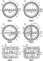
- FIG. 1 shows a schematic plan view of a receiving coil SA1 according to a first embodiment of the invention.
- the receiving coil assembly SA1 comprises an outer ferrite core FK1 and an inner ferrite core FK2 made of a ferromagnetic material.
- the outer ferrite core FK1 has an annular shape and has two air gaps LS (which are oversized for better illustration), which interrupt the outer ferrite core FK1 in its longitudinal extension direction ER1, so that the outer ferrite core FK1 is virtually divided into two C-shaped ferrite elements.
- the outer ferrite core FK1 each has a connecting part VT made of a non-ferromagnetic material, wherein the connecting parts VT fill the respective air gaps LS and are integrally formed with the two C-shaped ferrite elements.
- the two connecting parts VT connect the two ferrite elements together and hold them mechanically together.
- the outer ferrite core FK1 encloses a circular disk-shaped surface FL.
- the inner ferrite core FK2 is rod-shaped and is in the surface FL enclosed by the outer ferrite core FK1 arranged.
- the inner ferrite core FK2 is physically connected to the outer ferrite core FK1 via two connection points VS and extends along a center line of the surface FL from one connection point VS to another opposite connection point VS.
- the receiving coil assembly SA1 further includes an outer coil SP1 which is wound circumferentially along the longitudinal extension direction ER1 of the outer ferrite core FK1 and thus the outer ferrite core FK1 in the longitudinal extension direction ER1 thereof.
- the receiving coil assembly SA1 further includes an inner coil SP2 which extends along the longitudinal extension direction ER2 and over the entire length thereof and is helically wound around the inner ferrite core FK2.
- the inner coil SP2 forms a solenoid (solenoid).
- the outer and inner coils SP1, SP2 consist of one and the same copper wire with a corresponding electrical insulating layer.
- the two coils SP1, SP2 are connected in series with each other and have a common positive power connection PA and a common negative power connection NA.
- Induction currents, which under the action of one of an in FIG. 1 are shown in the outer and in the inner coil SP1, SP2 are added, added to a charging current I and supplied via the common positive power terminal PA and the common negative power connection NA, for example, a downstream traction battery of a hybrid electric vehicle.
- the receiving coil arrangement SA1 can be installed in an enveloping housing or encapsulated with an injection molding dimensions so that it can be installed in the hybrid electric vehicle in a stable and watertight manner, for example.
- the cross sections of the two ferrite cores FK1, FK2 and the mass of the ferromagnetic materials in the two ferrite cores FK1, FK2 may vary in their respective longitudinal extension directions ER1, ER2.
- outer ferrite cores FK1 which then together form an outer ferrite core group.
- the outer ferrite cores FK1 can be arranged one above the other, but also formed with different diameters and arranged coaxially with each other.
- the ferrite cores Fk1, FK2 may be deformed curved toward the transmitting coil assembly. This improves the magnetic coupling of the receiving coil arrangement SA1 to the transmitting coil arrangement.
- FIG. 2 shows a schematic plan view of a receiving coil SA2 according to a second embodiment of the invention.
- the receiving coil SA2 in FIG. 2 is different from the one in FIG. 1 shown receiving coil assembly SA1 characterized in that the outer and inner coil SP1, SP2 consist of two mutually (electrically) separate copper wires with corresponding electrical insulating layers and thus are connected in parallel to each other.
- the outer and inner coil SP1, SP2 consist of two mutually (electrically) separate copper wires with corresponding electrical insulating layers and thus are connected in parallel to each other.
- two induction currents can be generated, which are generated independently of each other by the two coils SP1, SP2 and can be supplied to the traction battery via separate electrical connections PA1, NA1 or PA2, NA2 of the two coils SP1, SP2.
- Additional (re) switches which are connected between power connections PA1, NA1, PA2, NA2, allow the two induction currents to be combined as required to form a charging current.
- FIG. 3 shows a schematic plan view of a receiving coil SA3 according to a third embodiment of the invention.
- the receiving coil SA3 in FIG. 3 is different from the one in FIG. 1 shown receiving coil assembly SA1 characterized in that the outer ferrite core FK1 is integrally formed and has no air gaps LS and no connection parts VT.
- the inner ferrite core FK2 has an air gap LS which is located in the center of the inner ferrite core FK2 and divides the inner ferrite core FK2 in its longitudinal extension direction ER2 into two ferrite elements.
- the inner ferrite core FK2 has a connecting part of a non-ferromagnetic material, which fills the air gap LS and is assembled with the two ferrite elements in one piece and mechanically fixed.
- the inner coil SP2 of the receiving coil assembly SA3 is not wound over the entire length of the inner ferrite core FK2, but only up to the air gap LS and thus only over half of the entire length of the inner ferrite core FK2.
- FIG. 4 shows a schematic plan view of a receiving coil SA4 according to a fourth embodiment of the invention.
- the receiving coil SA4 in FIG. 4 is different from the one in FIG. 1 in that the inner ferrite core FK2 is cross-shaped or has two rod-shaped ferrite elements FK21, FK22 made of the same ferromagnetic material (or also of two different ferromagnetic materials with different magnetic permeabilities) in the area framed by the outer ferrite core FK1 FL are arranged crosswise to each other and are formed integrally with each other.
- the inner coil SP2 of the receiving coil assembly SA4 is first helically wound around one of the two ferrite elements FK21 along the longitudinal extension direction ER2 thereof and over the entire length thereof. Thereafter, the inner coil SP2 is guided along the longitudinal extension direction ER1 of the outer ferrite core FK1 to a connection point VS of another ferrite element FK22. Subsequently, the inner coil SP2 is helically wound around this ferrite element FK22 along its longitudinal direction ER3 and over its entire length.
- the receiver coil arrangement SA4 has the advantage over the receiver coil arrangements SA1, SA2 and SA3 that these magnetic field components can accommodate both in three spatial directions.
- FIG. 5 shows a schematic plan view of a receiving coil SA5 according to a fifth embodiment of the invention.
- the receiving coil SA5 in FIG. 5 is different from the one in FIG. 1 shown receiving coil assembly SA1 characterized in that the outer ferrite core FK1 is not circular but square with rounded edges and thus has virtually a shape of a square ring.
- the inner coil SP1 of the receiving coil assembly SA5 is wound not only around the inner ferrite core FK2 but also helically wound around two opposite edges of the outer ferrite core FK1 extending in the longitudinal direction ER2 of the inner ferrite core FK2.
- the individual turns of the inner coil SP2 span the surface FL surrounded by the outer ferrite core FK1.
- FIG. 6 shows a schematic plan view of a receiving coil SA6 according to a sixth embodiment of the invention.
- the receiving coil SA6 in FIG. 6 is different from the one in FIG. 5 shown receive coil assembly SA5 characterized in that the inner ferrite core FK2 is assembled from three ferrite elements of different ferromagnetic materials.
- the three ferrite elements form three regions B1, B2 and B3 of the inner ferrite core FK2, which are arranged in the longitudinal direction ER2 of the inner ferrite core FK2 together and are physically connected to each other.
- FIG. 7 shows in a schematic side view one of the receiving coil arrangement shown above, wherein a winding form of the outer coil SP1 of the receiving coil assembly SA1 is exemplified.
- the outer coil SP1 is wound in this embodiment (multi-layer) helical or helical, wherein the individual windings WD1 of the outer coil SP1 in the height direction HR of the outer ferrite core FK1 considered one above the other.
- FIG. 8 shows in a schematic side view another of the receiving coil arrangement shown above, wherein a further winding form of the outer coil SP1 of the receiving coil assembly SA2 is exemplified.
- the outer coil SP1 is wound in a single layer in this embodiment in a spiral shape and thus wound away from the center of the surface FL framed by the outer ferrite core FK1, with the individual turns WD1 of the outer coil SP1 juxtaposed in the radial direction RR of the outer ferrite core FK1.
- FIG. 9 shows in a schematic side view, yet another of the receiving coil arrangement shown above, wherein a further winding form of the outer coil SP1 of the receiving coil assembly SA3 is exemplified.
- the outer coil SP1 is wound both helically and spirally in this embodiment, with individual ones Windings WD1 of the outer coil SP1 are both one above the other and next to each other.
- receiving coil arrangements SP1, SP2, SP3, SP4, SP5 and SP6 have one thing in common: they each comprise at least two ferrite cores FK1, FK2, which are shaped differently and preferably also consist of different ferromagnetic materials.
- the outer ferrite core FK1 of in FIG. 6 be shown assembled from a plurality of ferrite elements of different ferromagnetic materials receiving coil assembly SP6.
- the two ferrite cores FK1, FK2 of in FIGS. 1 to 5 Reception coil arrangement shown SP1, SP2, SP3, SP4 and SP5 also be assembled from a plurality of ferrite elements made of different ferromagnetic materials.
- a receiving coil device which comprises a plurality of receiving coil arrangements SP1, SP2, SP3, SP4, SP5 and / or SP6 described above, wherein the receiving coil arrangements SP1, SP2, SP3, SP4, SP5 and / or SP6 can also be used in mixed combination ,
- both vertical and horizontal field components of the magnetic field generated by the transmit coil assembly can be received and converted into power by the receive coil assembly SP1, SP2, SP3, SP4, SP5 or SP6 described above.
- the inner ferrite core FK2 of the receiver coil arrangement SP1, SP2, SP3, SP4, SP5 or SP6 described above can also be circular or rectangular disk-shaped and that of the respective outer ferrite core FK1 of the corresponding receiver coil arrangement Fill SP1, SP2, SP3, SP4, SP5, or SP6 bordered area FL to a circular or rectangular ring-shaped free edge area.
- Such an embodiment of the inner ferrite core FK2 has the advantage that the effective coil area of the inner coil SP2 is increased, which in turn allows more portions of the magnetic field to be received by the receiving coil array SP1, SP2, SP3, SP4, SP5 or SP6 and converted into electricity.
- the receiving coil arrangement SP1, SP2, SP3, SP4, SP5 or SP6 described above is, for example, arranged as part of a vehicle inductive charging device in an underbody of a hybrid electric vehicle and adapted to receive the magnetic field radiated by the transmitting coil arrangement of a stationary charging station arranged in the ground below the hybrid electric vehicle and convert it into electricity.
Landscapes
- Engineering & Computer Science (AREA)
- Power Engineering (AREA)
- Transportation (AREA)
- Mechanical Engineering (AREA)
- Charge And Discharge Circuits For Batteries Or The Like (AREA)
- Electric Propulsion And Braking For Vehicles (AREA)
Description
- Die vorliegende Erfindung betrifft eine Fahrzeug-Induktivladevorrichtung mit einer Empfangsspulenanordnung zum Induktivladen einer Batterie eines Fahrzeugs, insb. einer Traktionsbatterie eines Hybridelektro-/Elektrofahrzeugs.
- Ferner betrifft die Erfindung ein Fahrzeug, insb. ein Hybridelektro-/Elektrofahrzeug, mit einer genannten Fahrzeug-Induktivladevorrichtung sowie eine stationäre Ladestation mit einer Spulenanordnung, die gemäß der Empfangsspulenanordnung der genannten Fahrzeug-Induktivladevorrichtung ausgebildet ist.
- Es gibt Fahrzeuge mit Batterien, insb. Hybridelektro- oder Elektrofahrzeuge mit Traktionsbatterien, die von fahrzeugexternen Ladestationen induktiv aufgeladen werden. Das Induktivladen dieser Fahrzeuge erfolgt mittels einer ladestationsseitigen Primärspule (Sendespule) und einer fahrzeugseitigen Sekundärspule (Empfangsspule), wobei die Primärspule, welche mit Strom beaufschlagt wird, ein Magnetfeld mit einer Sendeleistung erzeugt, das von der Sekundärspule aufgenommen und in Ladestrom mit einer Ladeleistung umgewandelt wird. Umgekehrt kann auch die in der fahrzeugseitigen Batterie gespeicherte elektrische Leistung von der fahrzeugseitigen Sekundärspule, die in diesem Fall als Sendespule agiert, in Form vom Magnetfeld zu der ladestationsseitigen Primärspule, die in diesem Fall als Empfangsspule agiert, übertragen und einem öffentlichen Stromversorgungsnetz eingespeist werden.
- Eine Offenlegungsschrift
US 2004/119576 A1 beschreibt einen kontaktlosen Koppler, der zwei Magnetkerne umfasst, die jeweils einen U-förmigen offenen Magnetpfad aufweisen. Um die Magnetkerne sind jeweils eine Primärspule und eine Sekundärspule gewickelt. Der Koppler überträgt elektrische Wechselspannung zwischen der Primärspule und der Sekundärspule mittels eines ringförmigen geschlossenen magnetischen Pfades, der in der Nähe offener Stirnseiten der beiden Magnetkerne gebildet ist. - Eine weitere Offenlegungsschrift
DE 102 55 376 A1 beschreibt ein induktives Bauelement, das zwei, jeweils mit zumindest einem Luftspalt versehene, rahmenförmige Magnetkerne aufweist. Diese beiden Kerne sind in einem axialen Abstand übereinander angeordnet. Die Luftspalte sind dabei so angeordnet, dass sie sich in radialer Richtung diametral gegenüber stehen. Über die beiden Kerne ist eine Wicklung gewickelt, um eine Spule zu bilden. - Eine weitere Offenlegungsschrift
US 2014/265555 A1 beschreibt ein System zur drahtlosen Energieverteilung beschrieben. Das System umfasst einen Quellenresonator, der mit einer Energiequelle eines Fahrzeugs gekoppelt ist und ein oszillierendes Magnetfeld mit einer Frequenz erzeugt. Ein Verstärker-Resonator ist in der Nähe des Quellenresonators positioniert, der eine Resonanzfrequenz aufweist, die der Frequenz des Quellenresonators entspricht. Der Verstärker-Resonator stellt eine effektive drahtlose Energieübertragung innerhalb eines definierten Bereichs sicher. - Dabei ist bekannt, dass sich das von der Primärspule erzeugte Magnetfeld nicht nur in eine Raumrichtung, sondern in alle Himmelsrichtungen ausbreitet. Dies führt dazu, dass nur ein begrenzter Anteil der von der Primärspule generierten Sendeleistung von der Sekundärspule aufgenommen und in Ladeleistung umgewandelt werden kann. Dadurch wird der Wirkungsgrad bei dem Induktivladen beeinträchtigt.
- Damit besteht die Aufgabe der vorliegenden Erfindung darin, das Induktivladen eines Fahrzeugs effizienter zu machen.
- Diese Aufgabe wird durch Gegenstände der unabhängigen Ansprüche gelöst. Vorteilhafte Ausgestaltungen sind Gegenstand der Unteransprüche.
- Gemäß einem ersten Aspekt der Erfindung wird eine Fahrzeug-Induktivladevorrichtung mit einer Empfangsspulenanordnung zum Induktivladen einer Batterie eines Fahrzeugs, insb. einer Traktionsbatterie eines Hybridelektro- oder Elektrofahrzeugs, bereitgestellt.
- Die Empfangsspulenanordnung umfasst einen äußeren Ferritkern, der eine Fläche umschließend ausgebildet ist.
- Die Empfangsspulenanordnung umfasst ferner einen inneren Ferritkern, der über zumindest eine Verbindungsstelle mit dem äußeren Ferritkern körperlich verbunden ist und sich von dieser Verbindungsstelle aus im Wesentlichen in der von dem äußeren Ferritkern umrandeten Fläche erstreckt.
- Der Erfindung liegt der Gedanke zugrunde, dass der Wirkungsgrad bei dem Induktivladen dadurch erhöht werden kann, wenn die Sekundär- bzw. Empfangsspule das von der Primär- bzw. Sendespule erzeugte Magnetfeld effizienter empfängt und in elektrischen Strom umwandelt.
- Durch die Kombination zumindest eines äußeren Ferritkerns und zumindest eines inneren Ferritkerns mit unterschiedlichen Formen, wobei der äußere Ferritkern eine Fläche umrandet, in der der innere Ferritkern platziert ist, ist ermöglicht, sowohl vertikal verlaufende als auch horizontal verlaufende Magnetfeldkomponenten und somit insgesamt mehr Anteile von dem Magnetfeld zu empfangen und in Strom umzuwandeln.
- Damit kann mehr Sendeleistung, die von der Sendespule in Form von Magnetfeld der Empfangsspule gestrahlt wird, von der Empfangsspule bzw. der Empfangsspulenanordnung empfangen und in elektrischen Strom umgewandelt werden. Dadurch ist eine Möglichkeit bereitgestellt, eine Batterie eines Fahrzeugs effizienter induktiv zu laden.
- Die Empfangsspulenanordnung umfasst vorzugsweise ferner zumindest einen Luftspalt, der in dem äußeren Ferritkern, in dem inneren Ferritkern und/oder zwischen dem äußeren und dem inneren Ferritkern ausgebildet ist. Der zumindest eine Luftspalt unterbricht dabei den äußeren bzw. den inneren Ferritkern in dessen jeweiliger Längserstreckungsrichtung (bzw. Längsverlauf) und verhindert somit magnetische Kurzschlüsse in dem bzw. in den Ferritkernen.
- Vorzugsweise umfasst die Empfangsspulenanordnung ferner zumindest ein Verbindungsteil aus einem nicht-ferromagnetischen (und vorzugsweise auch elektrisch isolierenden) Material, das den zumindest einen Luftspalt füllt. Das Verbindungsmaterial verleiht dem bzw. den Ferritkernen und somit der Empfangsspulenanordnung mechanische Stabilität.
- Das Verbindungsmaterial kann bspw. aus Kunststoff oder Aluminium bestehen bzw. enthalten.
- Der äußere Ferritkern ist vorzugsweise im Wesentlichen ringförmig, wie z. B. kreisring-, ovalring- oder ellipsenringförmig, oder mehreckig, insb. mit abgerundeten Kanten, ausgebildet.
- Der innere Ferritkern ist vorzugsweise im Wesentlichen stabförmig ausgebildet.
- Alternativ ist der innere Ferritkern im Wesentlichen kreuzförmig, insb. speichenförmig, ausgebildet. Als "speichenförmig" wird insb. eine Form bezeichnet, bei der mehrere stabförmig verlaufende Abschnitte sich an einer gemeinsamen Stelle treffen bzw. kreuzen. Die Stelle ist in der Mitte bzw. in der Nähe der Mitte der Fläche.
- Die Empfangsspulenanordnung umfasst ferner eine äußere Spule, die entlang der Längserstreckungsrichtung des äußeren Ferritkerns gewickelt ist.
- Die Empfangsspulenanordnung umfasst vorzugsweise ferner eine innere Spule, die im Wesentlichen schrauben- bzw. helixförmig um zumindest einen Abschnitt des inneren Ferritkerns herum gewickelt ist.
- Vorzugsweise sind die äußere und die innere Spule (bspw. mittels eines Schalters) zueinander parallel oder seriell schaltbar ausgeführt.
- Vorzugsweise weist der äußere Ferritkern bzw. der innere Ferritkern zumindest zwei Bereiche auf, die unterschiedlich starke magnetische Permeabilitäten (magnetische Leitfähigkeiten) aufweisen.
- Gemäß einem weiteren Aspekt der Erfindung wird ein Fahrzeug mit einer Batterie, insb. ein Hybridelektro- oder Elektrofahrzeug mit einer Traktionsbatterie, bereitgestellt. Das Fahrzeug umfasst eine zuvor beschriebene Fahrzeug-Induktivladevorrichtung mit einer Empfangsspulenanordnung zum Induktivladen der Batterie bzw. der Traktionsbatterie.
- Gemäß noch einem weiteren Aspekt der Erfindung wird eine stationäre fahrzeugexterne Ladestation zum Induktivladen einer Batterie eines Fahrzeugs, insb. einer Traktionsbatterie eines Hybridelektro- oder Elektrofahrzeugs, bereitgestellt. Dabei umfasst die Ladestation eine Spulenanordnung, die gemäß der Empfangsspulenanordnung der zuvor beschriebenen Fahrzeug-Induktivladevorrichtung ausgebildet ist. Mithilfe dieser ladestationsseitigen Empfangsspulenanordnung und einer fahrzeugseitigen Sendespule kann die in der Batterie gespeicherte elektrische Leistung von dem Fahrzeug an die Ladestation übertragen und von der Ladestation einem (öffentlichen) Stromnetz gespeist werden.
- Vorteilhafte Ausgestaltungen der oben beschriebenen Empfangsspulenanordnung sind, soweit im Übrigen auf das oben genannte Fahrzeug oder auf die oben genannte Ladestation übertragbar, auch als vorteilhafte Ausgestaltungen des Fahrzeugs bzw. der Ladestation anzusehen.
- Im Folgenden werden beispielhafte Ausführungsformen der Erfindung bezugnehmend auf die beiliegende Zeichnung näher erläutert. Dabei zeigen:
- Figur 1
- in einer schematischen Draufsicht eine Empfangsspulenanordnung gemäß einer ersten Ausführungsform der Erfindung;
- Figur 2
- in einer schematischen Draufsicht eine Empfangsspulenanordnung gemäß einer zweiten Ausführungsform der Erfindung;
- Figur 3
- in einer schematischen Draufsicht eine Empfangsspulenanordnung gemäß einer dritten Ausführungsform der Erfindung;
- Figur 4
- in einer schematischen Draufsicht eine Empfangsspulenanordnung gemäß einer vierten Ausführungsform der Erfindung;
- Figur 5
- in einer schematischen Draufsicht eine Empfangsspulenanordnung gemäß einer fünften Ausführungsform der Erfindung;
- Figur 6
- in einer schematischen Draufsicht eine Empfangsspulenanordnung gemäß einer sechsten Ausführungsform der Erfindung;
- Figur 7
- in einer schematischen Seitensicht eine Empfangsspulenanordnung einer der in
Figuren 1 bis 6 dargestellten Ausführungsformen der Erfindung; - Figur 8
- in einer schematischen Seitensicht eine Empfangsspulenanordnung einer weiteren der in
Figuren 1 bis 6 dargestellten Ausführungsformen der Erfindung; - Figur 9
- in einer schematischen Seitensicht eine Empfangsspulenanordnung einer weiteren der in
Figuren 1 bis 6 dargestellten Ausführungsformen der Erfindung. -
Figur 1 zeigt in einer schematischen Draufsicht eine Empfangsspulenanordnung SA1 gemäß einer ersten Ausführungsform der Erfindung. - Die Empfangsspulenanordnung SA1 umfasst einen äußeren Ferritkern FK1 und einen inneren Ferritkern FK2 aus einem ferromagnetischen Material.
- Der äußere Ferritkern FK1 ist kreisringförmig ausgebildet und weist zwei Luftspalte LS (diese sind zur besseren Darstellung überdimensional dargestellt) auf, die den äußeren Ferritkern FK1 in dessen Längserstreckungsrichtung ER1 unterbrechen, so dass der äußere Ferritkern FK1 quasi in zwei C-förmigen Ferritelemente geteilt sind. In diesen Luftspalten LS weist der äußere Ferritkern FK1 jeweils ein Verbindungsteil VT aus einem nicht-ferromagnetischen Material auf, wobei die Verbindungsteile VT die jeweiligen Luftspalte LS füllen und mit den beiden C-förmigen Ferritelementen einstückig ausgebildet sind. Damit verbinden die beiden Verbindungsteile VT die beiden Ferritelemente miteinander und halten diese mechanisch fest zusammen.
- Der äußere Ferritkern FK1 umschließt eine kreisscheibenförmige Fläche FL.
- Der innere Ferritkern FK2 ist stabförmig ausgebildet und ist in der von dem äußeren Ferritkern FK1 umschlossenen Fläche FL angeordnet. Der innere Ferritkern FK2 ist über zwei Verbindungsstellen VS mit dem äußeren Ferritkern FK1 körperlich verbunden und erstreckt sich entlang einer Mittellinie der Fläche FL von einer Verbindungsstelle VS zu einer anderen gegenüberliegenden Verbindungsstelle VS.
- Die Empfangsspulenanordnung SA1 umfasst ferner eine äußere Spule SP1, die entlang der Längserstreckungsrichtung ER1 des äußeren Ferritkerns FK1 und somit den äußeren Ferritkern FK1 in dessen Längserstreckungsrichtung ER1 umlaufend gewickelt ist.
- Die Empfangsspulenanordnung SA1 umfasst ferner eine innere Spule SP2, die sich entlang dessen Längserstreckungsrichtung ER2 und über dessen gesamte Länge erstreckt und um den inneren Ferritkern FK2 herum helixförmig gewickelt ist. Damit bildet die innere Spule SP2 eine Zylinderspule (Solenoid) aus.
- Die äußere und die innere Spule SP1, SP2 bestehen aus einem und demselben Kupferdraht mit entsprechender elektrischer Isolierschicht. Damit sind die beiden Spulen SP1, SP2 zueinander in Serie geschaltet und weisen einen gemeinsamen positiven Stromanschluss PA und einen gemeinsamen negativen Stromanschluss NA auf. Induktionsströme, die unter Einwirkung von einem von einer in
Figur 1 nicht dargestellten Sendespulenanordnung ausgestrahlten Magnetfeld in der äußeren und in der inneren Spule SP1, SP2 induziert werden, werden zu einem Ladestrom I aufaddiert und über den gemeinsamen positiven Stromanschluss PA und den gemeinsamen negativen Stromanschluss NA bspw. einer nachgeschalteten Traktionsbatterie eines Hybridelektrofahrzeugs zugeführt. - Die Empfangsspulenanordnung SA1 kann in einem umhüllenden Gehäuse verbaut oder mit einer Spritzgussmaße umgossen sein, so dass diese stabil und wasserdicht bspw. in dem Hybridelektrofahrzeug verbaut werden kann.
- Die Querschnitte der beiden Ferritkerne FK1, FK2 bzw. die Masse von den ferromagnetischen Materialien in den beiden Ferritkernen FK1, FK2 können in deren jeweiligen Längserstreckungsrichtungen ER1, ER2 variieren.
- Es können auch zwei oder mehr äußere Ferritkerne FK1 vorgesehen sein, die dann zusammen eine äußere Ferritkerngruppe ausbilden. Dabei können die äußere Ferritkerne FK1 übereinander angeordnet sein, aber auch mit unterschiedlichen Durchmessern ausgebildet und zueinander koaxial angeordnet sein.
- Analog können auch zwei oder mehr innere Ferritkerne FK2 vorsehen sein, die dann in der von dem äußeren Ferritkern FK1 umrandeten Fläche FL nebeneinander, insb. zueinander parallel, angeordnet sein können.
- Ferner können die Ferritkerne Fk1, FK2 in Richtung zu der Sendespulenanordnung hin gewölbt verformt sein. Dadurch wird die magnetische Kopplung der Empfangsspulenanordnung SA1 an die Sendespulenanordnung verbessert.
-
Figur 2 zeigt in einer schematischen Draufsicht eine Empfangsspulenanordnung SA2 gemäß einer zweiten Ausführungsform der Erfindung. - Die Empfangsspulenanordnung SA2 in
Figur 2 unterscheidet sich von der inFigur 1 gezeigten Empfangsspulenanordnung SA1 dadurch, dass die äußere und die innere Spule SP1, SP2 aus zwei voneinander (elektrisch) getrennten Kupferdrähten mit entsprechenden elektrischen Isolierschichten bestehen und somit zueinander parallel geschaltet sind. Damit können zwei Induktionsströme generiert werden, die von den beiden Spulen SP1, SP2 voneinander unabhängig generiert und über voneinander elektrische getrennte Anschlüsse PA1, NA1 bzw. PA2, NA2 der beiden Spulen SP1, SP2 der Traktionsbatterie zugeführt werden können. - Durch zusätzliche (Um-)Schalter, die zwischen Stromanschlüssen PA1, NA1, PA2, NA2 angeschlossen werden, können die beiden Induktionsströme bei Bedarf zu einem Ladestrom zusammengeführt werden.
-
Figur 3 zeigt in einer schematischen Draufsicht eine Empfangsspulenanordnung SA3 gemäß einer dritten Ausführungsform der Erfindung. - Die Empfangsspulenanordnung SA3 in
Figur 3 unterscheidet sich von der inFigur 1 dargestellten Empfangsspulenanordnung SA1 dadurch, dass der äußere Ferritkern FK1 einstückig ausgebildet ist und keine Luftspalte LS bzw. keine Verbindungsteile VT aufweist. - Dagegen weist der innere Ferritkern FK2 einen Luftspalt LS, der sich in der Mitte des inneren Ferritkerns FK2 befindet und den inneren Ferritkern FK2 in dessen Längserstreckungsrichtung ER2 in zwei Ferritelemente teilt. In diesem Luftspalt LS weist der innere Ferritkern FK2 ein Verbindungsteil aus einem nicht-ferromagnetischen Material auf, das den Luftspalt LS füllt und mit den beiden Ferritelementen einstückig und mechanisch fest zusammengebaut ist.
- Zudem ist die innere Spule SP2 der Empfangsspulenanordnung SA3 nicht über die gesamte Länge des inneren Ferritkerns FK2, sondern lediglich bis zu dessen Luftspalt LS und somit nur über eine Hälfte der gesamten Länge des inneren Ferritkerns FK2 gewickelt.
-
Figur 4 zeigt in einer schematischen Draufsicht eine Empfangsspulenanordnung SA4 gemäß einer vierten Ausführungsform der Erfindung. - Die Empfangsspulenanordnung SA4 in
Figur 4 unterscheidet sich von der inFigur 1 dargestellten Empfangsspulenanordnung SA1 dadurch, dass der innere Ferritkern FK2 kreuzförmig ausgebildet ist bzw. zwei stabförmige Ferritelemente FK21, FK22 aus demselben ferromagnetischen Material (oder auch aus zwei unterschiedlichen ferromagnetischen Materialen mit unterschiedlichen magnetischen Permeabilitäten) aufweist, die in der von dem äußeren Ferritkern FK1 umrandeten Fläche FL zueinander kreuzförmig angeordnet sind und miteinander einstückig ausgebildet sind. - Die innere Spule SP2 der Empfangsspulenanordnung SA4 ist zuerst helixförmig um eins der beiden Ferritelemente FK21 herum entlang dessen Längserstreckungsrichtung ER2 und über dessen gesamten Länge gewickelt. Danach ist die innere Spule SP2 entlang der Längserstreckungsrichtung ER1 des äußeren Ferritkerns FK1 bis zu einer Verbindungsstelle VS eines anderen Ferritelements FK22 geführt. Anschließend ist die innere Spule SP2 helixförmig um dieses Ferritelement FK22 herum entlang dessen Längserstreckungsrichtung ER3 und über dessen gesamten Länge gewickelt.
- Die Empfangsspulenanordnung SA4 hat gegenüber den Empfangsspulenanordnungen SA1, SA2 und SA3 den Vorteil, dass diese Magnetfeldkomponenten sowohl in drei Raumrichtungen aufnehmen können.
-
Figur 5 zeigt in einer schematischen Draufsicht eine Empfangsspulenanordnung SA5 gemäß einer fünften Ausführungsform der Erfindung. - Die Empfangsspulenanordnung SA5 in
Figur 5 unterscheidet sich von der inFigur 1 dargestellten Empfangsspulenanordnung SA1 dadurch, dass der äußere Ferritkern FK1 nicht kreisrund sondern viereckig mit abgerundeten Kanten ausgebildet ist und somit quasi eine Form eines Viereckrings aufweist. - Die innere Spule SP1 der Empfangsspulenanordnung SA5 ist nicht nur um den inneren Ferritkern FK2 gewickelt, sondern auch um zwei gegenüberliegende Kanten des äußeren Ferritkerns FK1 helixförmig gewickelt, die sich in der Längserstreckungsrichtung ER2 des inneren Ferritkerns FK2 erstrecken. Damit überspannen die einzelnen Windungen der inneren Spule SP2 die von dem äußeren Ferritkern FK1 umrandete Fläche FL.
-
Figur 6 zeigt in einer schematischen Draufsicht eine Empfangsspulenanordnung SA6 gemäß einer sechsten Ausführungsform der Erfindung. - Die Empfangsspulenanordnung SA6 in
Figur 6 unterscheidet sich von der inFigur 5 dargestellten Empfangsspulenanordnung SA5 dadurch, dass der innere Ferritkern FK2 aus drei Ferritelementen aus unterschiedlichen ferromagnetischen Materialien zusammengebaut ist. Die drei Ferritelemente bilden drei Bereiche B1, B2 und B3 des inneren Ferritkerns FK2 aus, die in der Längserstreckungsrichtung ER2 des inneren Ferritkerns FK2 beieinander angeordnet sind und miteinander körperlich verbunden sind. -
Figur 7 zeigt in einer schematischen Seitensicht eine der oben dargestellten Empfangsspulenanordnung, wobei eine Wicklungsform der äußeren Spule SP1 der Empfangsspulenanordnung SA1 beispielhaft veranschaulicht ist. - Die äußere Spule SP1 ist in dieser Ausführungsform (mehrlagig) schrauben- oder helixförmig gewickelt, wobei die einzelnen Windungen WD1 der äußeren Spule SP1 in Höhenrichtung HR des äußeren Ferritkerns FK1 betrachtet übereinander liegen.
-
Figur 8 zeigt in einer schematischen Seitensicht eine weitere der oben dargestellten Empfangsspulenanordnung, wobei eine weitere Wicklungsform der äußeren Spule SP1 der Empfangsspulenanordnung SA2 beispielhaft veranschaulicht ist. - Die äußere Spule SP1 ist in dieser Ausführungsform einlagig spiralförmig und somit sich von dem Mittelpunkt der von dem äußeren Ferritkern FK1 umrandeten Fläche FL entfernend gewickelt, wobei die einzelnen Windungen WD1 der äußeren Spule SP1 in radialer Richtung RR des äußeren Ferritkerns FK1 betrachtet nebeneinander liegen.
-
Figur 9 zeigt in einer schematischen Seitensicht noch eine weitere der oben dargestellten Empfangsspulenanordnung, wobei eine weitere Wicklungsform der äußeren Spule SP1 der Empfangsspulenanordnung SA3 beispielhaft veranschaulicht ist. - Die äußere Spule SP1 ist in dieser Ausführungsform sowohl schraubenförmig als auch spiralförmig gewickelt, wobei einzelne Windungen WD1 der äußeren Spule SP1 sowohl übereinander als auch nebeneinander liegen.
- Die oben beschriebenen Empfangsspulenanordnungen SP1, SP2, SP3, SP4, SP5 bzw. SP6 haben eine Gemeinsamkeit, dass sie jeweils zumindest zwei Ferritkerne FK1, FK2 umfassen, die unterschiedlich geformt sind und vorzugsweise auch aus unterschiedlichen ferromagnetischen Materialien bestehen.
- Die Merkmale der oben beschriebenen Ausführungsformen können miteinander kombiniert werden, sofern sich die Kombination positiv auf den Wirkungsgrad der entsprechenden Empfangsspulenanordnung auswirkt. So kann bspw. der äußere Ferritkern FK1 der in
Figur 6 dargestellten Empfangsspulenanordnung SP6 aus mehreren Ferritelementen aus unterschiedlichen ferromagnetischen Materialien zusammengebaut sein. Analog können die beiden Ferritkerne FK1, FK2 der inFiguren 1 bis 5 dargestellten Empfangsspulenanordnung SP1, SP2, SP3, SP4 und SP5 auch aus mehreren Ferritelementen aus unterschiedlichen ferromagnetischen Materialien zusammengebaut sein. - Es kann auch eine Empfangsspulenvorrichtung vorgesehen sein, die mehrere zuvor beschriebene Empfangsspulenanordnungen SP1, SP2, SP3, SP4, SP5 und/oder SP6 umfasst, wobei die Empfangsspulenanordnungen SP1, SP2, SP3, SP4, SP5 und/oder SP6 auch gemischt kombiniert verwendet werden können.
- Durch die Kombination verschiedener Ferritkernformen mit unterschiedlich gewickelten Spulen SP1, SP2 können sowohl vertikale, als auch horizontale Feldkomponenten des von der Sendespulenanordnung erzeugten Magnetfeldes von der oben beschriebenen Empfangsspulenanordnung SP1, SP2, SP3, SP4, SP5 oder SP6 empfangen und in Strom umgewandelt werden.
- Der innere Ferritkern FK2 der oben beschriebenen Empfangsspulenanordnung SP1, SP2, SP3, SP4, SP5 oder SP6 kann auch kreis- oder rechteckscheibenförmig ausgebildet sein und die von dem jeweiligen äußeren Ferritkern FK1 der entsprechenden Empfangsspulenanordnung SP1, SP2, SP3, SP4, SP5 oder SP6 umrandeten Fläche FL bis auf einen kreis- oder rechteckringförmigen freien Randbereich vollständig füllen. Derartige Ausführung des inneren Ferritkerns FK2 hat den Vorteil, dass die effektive Spulenfläche der inneren Spule SP2 erhöht wird, wodurch wiederum mehr Anteile des magnetischen Feldes von der Empfangsspulenanordnung SP1, SP2, SP3, SP4, SP5 oder SP6 empfangen und in Strom umgewandelt werden können.
- Die zuvor beschriebene Empfangsspulenanordnung SP1, SP2, SP3, SP4, SP5 oder SP6 ist bspw. als Teil einer Fahrzeug-Induktivladevorrichtung in einem Unterboden eines Hybridelektrofahrzeugs angeordnet und eingerichtet, das von der im Boden unter dem Hybridelektrofahrzeug angeordneten Sendespulenanordnung einer stationären Ladestation ausgestrahlte Magnetfeld zu empfangen und in elektrischen Strom umzuwandeln.
Claims (11)
- Fahrzeug-Induktivladevorrichtung mit einer Empfangsspulenanordnung (SA1, SA2, SA3, SA4, SA5, SA6) zum Induktivladen eines Fahrzeugs, wobei die Empfangsspulenanordnung (SA1, SA2, SA3, SA4, SA5, SA6) umfasst:- einen äußeren Ferritkern (FK1), der eine Fläche (FL) umschließend geformt ist;- einen inneren Ferritkern (FK2), der über zumindest eine Verbindungsstelle (VS) mit dem äußeren Ferritkern (FK1) körperlich verbunden ist und sich von dieser Verbindungsstelle (VS) aus in der Fläche (FL) erstreckt,dadurch gekennzeichnet, dass- die Empfangsspulenanordnung (SA1, SA2, SA3, SA4, SA5, SA6) ferner eine äußere Spule (SP1) umfasst, die entlang einer Längserstreckungsrichtung (ER1) des äußeren Ferritkerns (FK1) um den äußeren Ferritkern (FK1) gewickelt ist.
- Fahrzeug-Induktivladevorrichtung nach Anspruch 1, wobei die Empfangsspulenanordnung (SA1, SA2, SA3, SA4, SA5, SA6) ferner zumindest einen Luftspalt (LS) aufweist, der in dem äußeren Ferritkern (FK1), in dem inneren Ferritkern (FK2), und/oder zwischen dem äußeren (FK1) und dem inneren (FK2) Ferritkern ausgebildet ist und den äußeren (FK1) bzw. den inneren (FK2) Ferritkern in dessen jeweiliger Längserstreckungsrichtung (ER1, ER2) unterbricht.
- Fahrzeug-Induktivladevorrichtung nach Anspruch 2, wobei die Empfangsspulenanordnung (SA1, SA2, SA3, SA4, SA5, SA6) ferner zumindest ein Verbindungsteil (VT) aus einem nicht-ferromagnetischen Material umfasst, das den zumindest einen Luftspalt (LS) füllt und der Empfangsspulenanordnung (SA1, SA2, SA3, SA4, SA5, SA6) mechanische Stabilität verleiht.
- Fahrzeug-Induktivladevorrichtung nach einem der vorangehenden Ansprüche, wobei der äußere Ferritkern (FK1) im Wesentlichen ringförmig oder mehreckig ausgebildet ist.
- Fahrzeug-Induktivladevorrichtung nach einem der vorangehenden Ansprüche, wobei der innere Ferritkern (FK2) im Wesentlichen stabförmig ausgebildet ist.
- Fahrzeug-Induktivladevorrichtung nach einem der Ansprüche 1 bis 4, wobei der innere Ferritkern (FK2) im Wesentlichen kreuzförmig, insb. speichenförmig, ausgebildet ist.
- Fahrzeug-Induktivladevorrichtung nach einem der vorangehenden Ansprüche, wobei die Empfangsspulenanordnung (SA1, SA2, SA3, SA4, SA5, SA6) ferner eine innere Spule (SP2) umfasst, die um zumindest einen Abschnitt des inneren Ferritkerns (FK2) herum gewickelt ist.
- Fahrzeug-Induktivladevorrichtung nach Anspruch 7, wobei die äußere (SP1) und die innere (SP2) Spule zueinander parallel oder seriell schaltbar ausgeführt sind.
- Fahrzeug-Induktivladevorrichtung nach einem der vorangehenden Ansprüche, wobei der äußere Ferritkern (FK1) bzw. der innere Ferritkern (FK2) zumindest zwei Bereiche (B1, B2, B3) aufweist, die unterschiedlich starke magnetische Permeabilitäten aufweisen.
- Fahrzeug mit einer Batterie, insb. Hybridelektro- oder Elektrofahrzeug mit einer Traktionsbatterie, umfassend eine Fahrzeug-Induktivladevorrichtung mit einer Empfangsspulenanordnung (SA1, SA2, SA3, SA4, SA5, SA6) nach einem der vorangehenden Ansprüche zum Induktivladen der Batterie.
- Stationäre Ladestation zum Induktivladen einer Batterie eines Fahrzeugs, insb. einer Traktionsbatterie eines Hybridelektro- oder Elektrofahrzeugs, umfassend eine Spulenanordnung, die gemäß der Empfangsspulenanordnung (SA1, SA2, SA3, SA4, SA5, SA6) der Fahrzeug-Induktivladevorrichtung nach einem der vorangehenden Ansprüche 1 bis 9 ausgebildet ist.
Applications Claiming Priority (2)
| Application Number | Priority Date | Filing Date | Title |
|---|---|---|---|
| DE102014225974.6A DE102014225974A1 (de) | 2014-12-16 | 2014-12-16 | Fahrzeug-Induktivladevorrichtung zum Induktivladen eines Fahrzeugs, Fahrzeug bzw. stationäre Ladestation |
| PCT/EP2015/078497 WO2016096455A1 (de) | 2014-12-16 | 2015-12-03 | Fahrzeug-induktivladevorrichtung zum induktivladen eines fahrzeugs, fahrzeug bzw. stationäre ladestation |
Publications (2)
| Publication Number | Publication Date |
|---|---|
| EP3234966A1 EP3234966A1 (de) | 2017-10-25 |
| EP3234966B1 true EP3234966B1 (de) | 2019-08-07 |
Family
ID=54782714
Family Applications (1)
| Application Number | Title | Priority Date | Filing Date |
|---|---|---|---|
| EP15804768.8A Active EP3234966B1 (de) | 2014-12-16 | 2015-12-03 | Fahrzeug-induktivladevorrichtung zum induktivladen eines fahrzeugs, fahrzeug bzw. stationäre ladestation |
Country Status (3)
| Country | Link |
|---|---|
| EP (1) | EP3234966B1 (de) |
| DE (1) | DE102014225974A1 (de) |
| WO (1) | WO2016096455A1 (de) |
Families Citing this family (2)
| Publication number | Priority date | Publication date | Assignee | Title |
|---|---|---|---|---|
| CN111775738A (zh) * | 2020-07-28 | 2020-10-16 | 重庆华创智能科技研究院有限公司 | 一种提升无人机无线充电系统抗偏移能力的耦合机构 |
| US20230253148A1 (en) * | 2022-02-09 | 2023-08-10 | Quantage, Inc. | Signal coupling device |
Family Cites Families (7)
| Publication number | Priority date | Publication date | Assignee | Title |
|---|---|---|---|---|
| WO2002065493A1 (fr) * | 2001-02-14 | 2002-08-22 | Fdk Corporation | Coupleur sans contact |
| DE10255376A1 (de) * | 2002-11-27 | 2004-06-17 | Siemens Ag | Induktives Bauelement und Vorrichtung zum induktiven Übertragen von Energie und/oder Daten |
| US20070131505A1 (en) * | 2005-07-16 | 2007-06-14 | Kim Bryan H J | Magnetic Induction Charging System for Vehicles |
| DE202012101403U1 (de) * | 2012-04-17 | 2013-07-18 | Conductix-Wampfler Gmbh | Spuleneinheit und Elektrofahrzeug |
| US10553351B2 (en) * | 2012-05-04 | 2020-02-04 | Delta Electronics (Thailand) Public Co., Ltd. | Multiple cells magnetic structure for wireless power |
| DE102013101150A1 (de) * | 2013-02-05 | 2014-08-21 | Conductix-Wampfler Gmbh | Spuleneinheit und Vorrichtung zur induktiven Übertragung elektrischer Energie |
| US20140265555A1 (en) * | 2013-03-15 | 2014-09-18 | Witricity Corporation | Series relayed wireless power transfer in a vehicle |
-
2014
- 2014-12-16 DE DE102014225974.6A patent/DE102014225974A1/de not_active Ceased
-
2015
- 2015-12-03 WO PCT/EP2015/078497 patent/WO2016096455A1/de not_active Ceased
- 2015-12-03 EP EP15804768.8A patent/EP3234966B1/de active Active
Non-Patent Citations (1)
| Title |
|---|
| None * |
Also Published As
| Publication number | Publication date |
|---|---|
| DE102014225974A1 (de) | 2016-06-16 |
| EP3234966A1 (de) | 2017-10-25 |
| WO2016096455A1 (de) | 2016-06-23 |
Similar Documents
| Publication | Publication Date | Title |
|---|---|---|
| EP2450921B1 (de) | Ladevorrichtung, Empfangsstation sowie Steckvorrichtung zur induktiven Übertragung von elektrischer Energie | |
| EP2953812B1 (de) | Vorrichtung mit wicklungsanordnung und anordnung, insbesondere ladestation, zur berührungslosen energieübertragung an ein elektro-fahrzeug, mit einer wicklungsanordnung | |
| EP2659497B1 (de) | Flachspule für kontaktlose induktive energieübertragung | |
| WO2014122121A1 (de) | Spuleneinheit und vorrichtung zur induktiven übertragung elektrischer energie | |
| DE102012209898A1 (de) | Anordnung zur induktiven drahtlosen Abgabe von Energie | |
| EP3026684B1 (de) | Sendespule für ein kontaktloses Energieübertragungssystem mit verbesserter Kopplung und verbessertem Streufeld | |
| DE112019003942T5 (de) | Drahtgebundenes/drahtloses integriertes Leistungsempfangssystem | |
| EP3545537B1 (de) | Induktives bauelement und sekundärresonatoreinrichtung zur montage an einem elektrokraftfahrzeug | |
| EP2603920B1 (de) | Spulenanordnung, insbesondere wechselstrom-transformator, verwendung und anordnung zur berührungslosen energieübertragung | |
| DE102014225974A1 (de) | Fahrzeug-Induktivladevorrichtung zum Induktivladen eines Fahrzeugs, Fahrzeug bzw. stationäre Ladestation | |
| WO2018065451A1 (de) | Spuleneinheit zum induktiven laden eines fahrzeuges | |
| WO2023186750A1 (de) | Induktive ladeeinrichtung für ein fahrzeugladesystem | |
| DE102022125039A1 (de) | Induktive Ladeeinrichtung für ein Fahrzeugladesystem | |
| DE102014116901A1 (de) | Wicklungsanordnung für ein induktives Energieübertragungssystem | |
| WO2015144619A1 (de) | Magnetischer kreis zum dynamischen laden von elektrofahrzeugen | |
| WO2018192771A1 (de) | Spule geeignet für ein induktives ladesystem mit zwei teilspulen | |
| WO2016000991A1 (de) | Vorrichtung zum induktiven laden eines elektrischen speichers | |
| EP2973622A1 (de) | Wicklungsanordnung, welche teilwicklungen aufweist, und anordnung, insbesondere ladestation, zur berührungslosen energieübertragung an ein elektro-fahrzeug, mit einer wicklungsanordnung | |
| DE102013219714A1 (de) | Anordnung einer Elektronik bei einem System zur induktiven Energieübertragung | |
| WO2017220277A1 (de) | Vorrichtung zur induktiven energieübertragung | |
| DE102013111433A1 (de) | Planare symmetrische Spule für integrierte HF-Schaltungen | |
| DE102017130471A1 (de) | Transformatorvorrichtung für eine Ladestation zum elektrischen Laden von Fahrzeugen mit wenigstens zwei Ladepunkten | |
| DE102010054848A1 (de) | Vorrichtung zur induktiven Übertragung elektrischer Energie | |
| DE102019109110B4 (de) | Spulenkörper und Vorrichtung mit Spulenkörper | |
| DE102013100175A1 (de) | Spulenanordnung zum Induzieren und Bereitstellen einer Spannung zum Aufladen eines Ladungsspeichers |
Legal Events
| Date | Code | Title | Description |
|---|---|---|---|
| STAA | Information on the status of an ep patent application or granted ep patent |
Free format text: STATUS: THE INTERNATIONAL PUBLICATION HAS BEEN MADE |
|
| PUAI | Public reference made under article 153(3) epc to a published international application that has entered the european phase |
Free format text: ORIGINAL CODE: 0009012 |
|
| STAA | Information on the status of an ep patent application or granted ep patent |
Free format text: STATUS: REQUEST FOR EXAMINATION WAS MADE |
|
| 17P | Request for examination filed |
Effective date: 20170717 |
|
| AK | Designated contracting states |
Kind code of ref document: A1 Designated state(s): AL AT BE BG CH CY CZ DE DK EE ES FI FR GB GR HR HU IE IS IT LI LT LU LV MC MK MT NL NO PL PT RO RS SE SI SK SM TR |
|
| AX | Request for extension of the european patent |
Extension state: BA ME |
|
| DAV | Request for validation of the european patent (deleted) | ||
| DAX | Request for extension of the european patent (deleted) | ||
| GRAP | Despatch of communication of intention to grant a patent |
Free format text: ORIGINAL CODE: EPIDOSNIGR1 |
|
| STAA | Information on the status of an ep patent application or granted ep patent |
Free format text: STATUS: GRANT OF PATENT IS INTENDED |
|
| RIC1 | Information provided on ipc code assigned before grant |
Ipc: B60L 53/12 20190101ALI20190207BHEP Ipc: H01F 38/14 20060101AFI20190207BHEP |
|
| INTG | Intention to grant announced |
Effective date: 20190307 |
|
| GRAS | Grant fee paid |
Free format text: ORIGINAL CODE: EPIDOSNIGR3 |
|
| GRAA | (expected) grant |
Free format text: ORIGINAL CODE: 0009210 |
|
| STAA | Information on the status of an ep patent application or granted ep patent |
Free format text: STATUS: THE PATENT HAS BEEN GRANTED |
|
| AK | Designated contracting states |
Kind code of ref document: B1 Designated state(s): AL AT BE BG CH CY CZ DE DK EE ES FI FR GB GR HR HU IE IS IT LI LT LU LV MC MK MT NL NO PL PT RO RS SE SI SK SM TR |
|
| REG | Reference to a national code |
Ref country code: GB Ref legal event code: FG4D Free format text: NOT ENGLISH |
|
| REG | Reference to a national code |
Ref country code: CH Ref legal event code: EP Ref country code: AT Ref legal event code: REF Ref document number: 1165108 Country of ref document: AT Kind code of ref document: T Effective date: 20190815 |
|
| REG | Reference to a national code |
Ref country code: DE Ref legal event code: R096 Ref document number: 502015009928 Country of ref document: DE |
|
| REG | Reference to a national code |
Ref country code: IE Ref legal event code: FG4D Free format text: LANGUAGE OF EP DOCUMENT: GERMAN |
|
| REG | Reference to a national code |
Ref country code: NL Ref legal event code: MP Effective date: 20190807 |
|
| REG | Reference to a national code |
Ref country code: LT Ref legal event code: MG4D |
|
| PG25 | Lapsed in a contracting state [announced via postgrant information from national office to epo] |
Ref country code: BG Free format text: LAPSE BECAUSE OF FAILURE TO SUBMIT A TRANSLATION OF THE DESCRIPTION OR TO PAY THE FEE WITHIN THE PRESCRIBED TIME-LIMIT Effective date: 20191107 Ref country code: SE Free format text: LAPSE BECAUSE OF FAILURE TO SUBMIT A TRANSLATION OF THE DESCRIPTION OR TO PAY THE FEE WITHIN THE PRESCRIBED TIME-LIMIT Effective date: 20190807 Ref country code: NL Free format text: LAPSE BECAUSE OF FAILURE TO SUBMIT A TRANSLATION OF THE DESCRIPTION OR TO PAY THE FEE WITHIN THE PRESCRIBED TIME-LIMIT Effective date: 20190807 Ref country code: HR Free format text: LAPSE BECAUSE OF FAILURE TO SUBMIT A TRANSLATION OF THE DESCRIPTION OR TO PAY THE FEE WITHIN THE PRESCRIBED TIME-LIMIT Effective date: 20190807 Ref country code: LT Free format text: LAPSE BECAUSE OF FAILURE TO SUBMIT A TRANSLATION OF THE DESCRIPTION OR TO PAY THE FEE WITHIN THE PRESCRIBED TIME-LIMIT Effective date: 20190807 Ref country code: PT Free format text: LAPSE BECAUSE OF FAILURE TO SUBMIT A TRANSLATION OF THE DESCRIPTION OR TO PAY THE FEE WITHIN THE PRESCRIBED TIME-LIMIT Effective date: 20191209 Ref country code: FI Free format text: LAPSE BECAUSE OF FAILURE TO SUBMIT A TRANSLATION OF THE DESCRIPTION OR TO PAY THE FEE WITHIN THE PRESCRIBED TIME-LIMIT Effective date: 20190807 Ref country code: NO Free format text: LAPSE BECAUSE OF FAILURE TO SUBMIT A TRANSLATION OF THE DESCRIPTION OR TO PAY THE FEE WITHIN THE PRESCRIBED TIME-LIMIT Effective date: 20191107 |
|
| PG25 | Lapsed in a contracting state [announced via postgrant information from national office to epo] |
Ref country code: AL Free format text: LAPSE BECAUSE OF FAILURE TO SUBMIT A TRANSLATION OF THE DESCRIPTION OR TO PAY THE FEE WITHIN THE PRESCRIBED TIME-LIMIT Effective date: 20190807 Ref country code: ES Free format text: LAPSE BECAUSE OF FAILURE TO SUBMIT A TRANSLATION OF THE DESCRIPTION OR TO PAY THE FEE WITHIN THE PRESCRIBED TIME-LIMIT Effective date: 20190807 Ref country code: RS Free format text: LAPSE BECAUSE OF FAILURE TO SUBMIT A TRANSLATION OF THE DESCRIPTION OR TO PAY THE FEE WITHIN THE PRESCRIBED TIME-LIMIT Effective date: 20190807 Ref country code: IS Free format text: LAPSE BECAUSE OF FAILURE TO SUBMIT A TRANSLATION OF THE DESCRIPTION OR TO PAY THE FEE WITHIN THE PRESCRIBED TIME-LIMIT Effective date: 20191207 Ref country code: LV Free format text: LAPSE BECAUSE OF FAILURE TO SUBMIT A TRANSLATION OF THE DESCRIPTION OR TO PAY THE FEE WITHIN THE PRESCRIBED TIME-LIMIT Effective date: 20190807 Ref country code: GR Free format text: LAPSE BECAUSE OF FAILURE TO SUBMIT A TRANSLATION OF THE DESCRIPTION OR TO PAY THE FEE WITHIN THE PRESCRIBED TIME-LIMIT Effective date: 20191108 |
|
| PG25 | Lapsed in a contracting state [announced via postgrant information from national office to epo] |
Ref country code: TR Free format text: LAPSE BECAUSE OF FAILURE TO SUBMIT A TRANSLATION OF THE DESCRIPTION OR TO PAY THE FEE WITHIN THE PRESCRIBED TIME-LIMIT Effective date: 20190807 |
|
| PG25 | Lapsed in a contracting state [announced via postgrant information from national office to epo] |
Ref country code: IT Free format text: LAPSE BECAUSE OF FAILURE TO SUBMIT A TRANSLATION OF THE DESCRIPTION OR TO PAY THE FEE WITHIN THE PRESCRIBED TIME-LIMIT Effective date: 20190807 Ref country code: RO Free format text: LAPSE BECAUSE OF FAILURE TO SUBMIT A TRANSLATION OF THE DESCRIPTION OR TO PAY THE FEE WITHIN THE PRESCRIBED TIME-LIMIT Effective date: 20190807 Ref country code: EE Free format text: LAPSE BECAUSE OF FAILURE TO SUBMIT A TRANSLATION OF THE DESCRIPTION OR TO PAY THE FEE WITHIN THE PRESCRIBED TIME-LIMIT Effective date: 20190807 Ref country code: PL Free format text: LAPSE BECAUSE OF FAILURE TO SUBMIT A TRANSLATION OF THE DESCRIPTION OR TO PAY THE FEE WITHIN THE PRESCRIBED TIME-LIMIT Effective date: 20190807 Ref country code: DK Free format text: LAPSE BECAUSE OF FAILURE TO SUBMIT A TRANSLATION OF THE DESCRIPTION OR TO PAY THE FEE WITHIN THE PRESCRIBED TIME-LIMIT Effective date: 20190807 |
|
| RAP2 | Party data changed (patent owner data changed or rights of a patent transferred) |
Owner name: VITESCO TECHNOLOGIES GMBH |
|
| PG25 | Lapsed in a contracting state [announced via postgrant information from national office to epo] |
Ref country code: SK Free format text: LAPSE BECAUSE OF FAILURE TO SUBMIT A TRANSLATION OF THE DESCRIPTION OR TO PAY THE FEE WITHIN THE PRESCRIBED TIME-LIMIT Effective date: 20190807 Ref country code: IS Free format text: LAPSE BECAUSE OF FAILURE TO SUBMIT A TRANSLATION OF THE DESCRIPTION OR TO PAY THE FEE WITHIN THE PRESCRIBED TIME-LIMIT Effective date: 20200224 Ref country code: SM Free format text: LAPSE BECAUSE OF FAILURE TO SUBMIT A TRANSLATION OF THE DESCRIPTION OR TO PAY THE FEE WITHIN THE PRESCRIBED TIME-LIMIT Effective date: 20190807 Ref country code: CZ Free format text: LAPSE BECAUSE OF FAILURE TO SUBMIT A TRANSLATION OF THE DESCRIPTION OR TO PAY THE FEE WITHIN THE PRESCRIBED TIME-LIMIT Effective date: 20190807 |
|
| REG | Reference to a national code |
Ref country code: DE Ref legal event code: R081 Ref document number: 502015009928 Country of ref document: DE Owner name: VITESCO TECHNOLOGIES GMBH, DE Free format text: FORMER OWNER: CONTINENTAL AUTOMOTIVE GMBH, 30165 HANNOVER, DE Ref country code: DE Ref legal event code: R097 Ref document number: 502015009928 Country of ref document: DE |
|
| PLBE | No opposition filed within time limit |
Free format text: ORIGINAL CODE: 0009261 |
|
| STAA | Information on the status of an ep patent application or granted ep patent |
Free format text: STATUS: NO OPPOSITION FILED WITHIN TIME LIMIT |
|
| PG2D | Information on lapse in contracting state deleted |
Ref country code: IS |
|
| REG | Reference to a national code |
Ref country code: CH Ref legal event code: PL |
|
| 26N | No opposition filed |
Effective date: 20200603 |
|
| REG | Reference to a national code |
Ref country code: BE Ref legal event code: MM Effective date: 20191231 |
|
| PG25 | Lapsed in a contracting state [announced via postgrant information from national office to epo] |
Ref country code: MC Free format text: LAPSE BECAUSE OF FAILURE TO SUBMIT A TRANSLATION OF THE DESCRIPTION OR TO PAY THE FEE WITHIN THE PRESCRIBED TIME-LIMIT Effective date: 20190807 Ref country code: SI Free format text: LAPSE BECAUSE OF FAILURE TO SUBMIT A TRANSLATION OF THE DESCRIPTION OR TO PAY THE FEE WITHIN THE PRESCRIBED TIME-LIMIT Effective date: 20190807 |
|
| GBPC | Gb: european patent ceased through non-payment of renewal fee |
Effective date: 20191203 |
|
| PG25 | Lapsed in a contracting state [announced via postgrant information from national office to epo] |
Ref country code: FR Free format text: LAPSE BECAUSE OF NON-PAYMENT OF DUE FEES Effective date: 20191231 Ref country code: IE Free format text: LAPSE BECAUSE OF NON-PAYMENT OF DUE FEES Effective date: 20191203 Ref country code: LU Free format text: LAPSE BECAUSE OF NON-PAYMENT OF DUE FEES Effective date: 20191203 Ref country code: GB Free format text: LAPSE BECAUSE OF NON-PAYMENT OF DUE FEES Effective date: 20191203 |
|
| PG25 | Lapsed in a contracting state [announced via postgrant information from national office to epo] |
Ref country code: LI Free format text: LAPSE BECAUSE OF NON-PAYMENT OF DUE FEES Effective date: 20191231 Ref country code: CH Free format text: LAPSE BECAUSE OF NON-PAYMENT OF DUE FEES Effective date: 20191231 Ref country code: BE Free format text: LAPSE BECAUSE OF NON-PAYMENT OF DUE FEES Effective date: 20191231 |
|
| PG25 | Lapsed in a contracting state [announced via postgrant information from national office to epo] |
Ref country code: CY Free format text: LAPSE BECAUSE OF FAILURE TO SUBMIT A TRANSLATION OF THE DESCRIPTION OR TO PAY THE FEE WITHIN THE PRESCRIBED TIME-LIMIT Effective date: 20190807 |
|
| PG25 | Lapsed in a contracting state [announced via postgrant information from national office to epo] |
Ref country code: MT Free format text: LAPSE BECAUSE OF FAILURE TO SUBMIT A TRANSLATION OF THE DESCRIPTION OR TO PAY THE FEE WITHIN THE PRESCRIBED TIME-LIMIT Effective date: 20190807 Ref country code: HU Free format text: LAPSE BECAUSE OF FAILURE TO SUBMIT A TRANSLATION OF THE DESCRIPTION OR TO PAY THE FEE WITHIN THE PRESCRIBED TIME-LIMIT; INVALID AB INITIO Effective date: 20151203 |
|
| REG | Reference to a national code |
Ref country code: DE Ref legal event code: R081 Ref document number: 502015009928 Country of ref document: DE Owner name: SCHAEFFLER TECHNOLOGIES AG & CO. KG, DE Free format text: FORMER OWNER: VITESCO TECHNOLOGIES GMBH, 30165 HANNOVER, DE Ref country code: DE Ref legal event code: R081 Ref document number: 502015009928 Country of ref document: DE Owner name: VITESCO TECHNOLOGIES GMBH, DE Free format text: FORMER OWNER: VITESCO TECHNOLOGIES GMBH, 30165 HANNOVER, DE |
|
| REG | Reference to a national code |
Ref country code: AT Ref legal event code: MM01 Ref document number: 1165108 Country of ref document: AT Kind code of ref document: T Effective date: 20201203 |
|
| PG25 | Lapsed in a contracting state [announced via postgrant information from national office to epo] |
Ref country code: AT Free format text: LAPSE BECAUSE OF NON-PAYMENT OF DUE FEES Effective date: 20201203 |
|
| PG25 | Lapsed in a contracting state [announced via postgrant information from national office to epo] |
Ref country code: MK Free format text: LAPSE BECAUSE OF FAILURE TO SUBMIT A TRANSLATION OF THE DESCRIPTION OR TO PAY THE FEE WITHIN THE PRESCRIBED TIME-LIMIT Effective date: 20190807 |
|
| P01 | Opt-out of the competence of the unified patent court (upc) registered |
Effective date: 20230530 |
|
| REG | Reference to a national code |
Ref country code: DE Ref legal event code: R081 Ref document number: 502015009928 Country of ref document: DE Owner name: SCHAEFFLER TECHNOLOGIES AG & CO. KG, DE Free format text: FORMER OWNER: VITESCO TECHNOLOGIES GMBH, 93055 REGENSBURG, DE |
|
| PGFP | Annual fee paid to national office [announced via postgrant information from national office to epo] |
Ref country code: DE Payment date: 20251231 Year of fee payment: 11 |