EP3234672B1 - Gehärteter glasfaserverbinder mit vorkomprimierter feder - Google Patents
Gehärteter glasfaserverbinder mit vorkomprimierter feder Download PDFInfo
- Publication number
- EP3234672B1 EP3234672B1 EP14908248.9A EP14908248A EP3234672B1 EP 3234672 B1 EP3234672 B1 EP 3234672B1 EP 14908248 A EP14908248 A EP 14908248A EP 3234672 B1 EP3234672 B1 EP 3234672B1
- Authority
- EP
- European Patent Office
- Prior art keywords
- ferrule
- connector
- fiber optic
- spring
- plug body
- Prior art date
- Legal status (The legal status is an assumption and is not a legal conclusion. Google has not performed a legal analysis and makes no representation as to the accuracy of the status listed.)
- Active
Links
- 239000000835 fiber Substances 0.000 title claims description 237
- 239000013307 optical fiber Substances 0.000 claims description 78
- 238000000034 method Methods 0.000 claims description 19
- 230000008878 coupling Effects 0.000 claims description 18
- 238000010168 coupling process Methods 0.000 claims description 18
- 238000005859 coupling reaction Methods 0.000 claims description 18
- 239000000853 adhesive Substances 0.000 claims description 11
- 230000001070 adhesive effect Effects 0.000 claims description 11
- 230000006835 compression Effects 0.000 claims description 6
- 238000007906 compression Methods 0.000 claims description 6
- 230000013011 mating Effects 0.000 description 29
- 238000005253 cladding Methods 0.000 description 7
- 238000007789 sealing Methods 0.000 description 7
- 239000004593 Epoxy Substances 0.000 description 6
- 238000003780 insertion Methods 0.000 description 6
- 230000037431 insertion Effects 0.000 description 6
- 239000000428 dust Substances 0.000 description 5
- 239000000463 material Substances 0.000 description 5
- 239000002184 metal Substances 0.000 description 5
- 230000000717 retained effect Effects 0.000 description 5
- 238000004891 communication Methods 0.000 description 4
- 230000006870 function Effects 0.000 description 4
- 238000004519 manufacturing process Methods 0.000 description 3
- 230000008569 process Effects 0.000 description 3
- 239000000356 contaminant Substances 0.000 description 2
- 230000007613 environmental effect Effects 0.000 description 2
- 230000003287 optical effect Effects 0.000 description 2
- 238000004904 shortening Methods 0.000 description 2
- 238000004873 anchoring Methods 0.000 description 1
- 239000004760 aramid Substances 0.000 description 1
- 229920003235 aromatic polyamide Polymers 0.000 description 1
- 230000008901 benefit Effects 0.000 description 1
- 238000004140 cleaning Methods 0.000 description 1
- 230000000694 effects Effects 0.000 description 1
- 230000002708 enhancing effect Effects 0.000 description 1
- 230000004927 fusion Effects 0.000 description 1
- 238000005498 polishing Methods 0.000 description 1
- 238000002360 preparation method Methods 0.000 description 1
- 230000003014 reinforcing effect Effects 0.000 description 1
- 238000007493 shaping process Methods 0.000 description 1
Images


Classifications
-
- G—PHYSICS
- G02—OPTICS
- G02B—OPTICAL ELEMENTS, SYSTEMS OR APPARATUS
- G02B6/00—Light guides; Structural details of arrangements comprising light guides and other optical elements, e.g. couplings
- G02B6/24—Coupling light guides
- G02B6/36—Mechanical coupling means
- G02B6/38—Mechanical coupling means having fibre to fibre mating means
- G02B6/3807—Dismountable connectors, i.e. comprising plugs
- G02B6/381—Dismountable connectors, i.e. comprising plugs of the ferrule type, e.g. fibre ends embedded in ferrules, connecting a pair of fibres
- G02B6/3818—Dismountable connectors, i.e. comprising plugs of the ferrule type, e.g. fibre ends embedded in ferrules, connecting a pair of fibres of a low-reflection-loss type
- G02B6/3821—Dismountable connectors, i.e. comprising plugs of the ferrule type, e.g. fibre ends embedded in ferrules, connecting a pair of fibres of a low-reflection-loss type with axial spring biasing or loading means
-
- G—PHYSICS
- G02—OPTICS
- G02B—OPTICAL ELEMENTS, SYSTEMS OR APPARATUS
- G02B6/00—Light guides; Structural details of arrangements comprising light guides and other optical elements, e.g. couplings
- G02B6/24—Coupling light guides
- G02B6/36—Mechanical coupling means
- G02B6/38—Mechanical coupling means having fibre to fibre mating means
- G02B6/3807—Dismountable connectors, i.e. comprising plugs
- G02B6/381—Dismountable connectors, i.e. comprising plugs of the ferrule type, e.g. fibre ends embedded in ferrules, connecting a pair of fibres
- G02B6/3816—Dismountable connectors, i.e. comprising plugs of the ferrule type, e.g. fibre ends embedded in ferrules, connecting a pair of fibres for use under water, high pressure connectors
-
- G—PHYSICS
- G02—OPTICS
- G02B—OPTICAL ELEMENTS, SYSTEMS OR APPARATUS
- G02B6/00—Light guides; Structural details of arrangements comprising light guides and other optical elements, e.g. couplings
- G02B6/24—Coupling light guides
- G02B6/36—Mechanical coupling means
- G02B6/38—Mechanical coupling means having fibre to fibre mating means
- G02B6/3807—Dismountable connectors, i.e. comprising plugs
- G02B6/381—Dismountable connectors, i.e. comprising plugs of the ferrule type, e.g. fibre ends embedded in ferrules, connecting a pair of fibres
- G02B6/3825—Dismountable connectors, i.e. comprising plugs of the ferrule type, e.g. fibre ends embedded in ferrules, connecting a pair of fibres with an intermediate part, e.g. adapter, receptacle, linking two plugs
-
- G—PHYSICS
- G02—OPTICS
- G02B—OPTICAL ELEMENTS, SYSTEMS OR APPARATUS
- G02B6/00—Light guides; Structural details of arrangements comprising light guides and other optical elements, e.g. couplings
- G02B6/24—Coupling light guides
- G02B6/36—Mechanical coupling means
- G02B6/38—Mechanical coupling means having fibre to fibre mating means
- G02B6/3807—Dismountable connectors, i.e. comprising plugs
- G02B6/3833—Details of mounting fibres in ferrules; Assembly methods; Manufacture
- G02B6/3847—Details of mounting fibres in ferrules; Assembly methods; Manufacture with means preventing fibre end damage, e.g. recessed fibre surfaces
- G02B6/3849—Details of mounting fibres in ferrules; Assembly methods; Manufacture with means preventing fibre end damage, e.g. recessed fibre surfaces using mechanical protective elements, e.g. caps, hoods, sealing membranes
-
- G—PHYSICS
- G02—OPTICS
- G02B—OPTICAL ELEMENTS, SYSTEMS OR APPARATUS
- G02B6/00—Light guides; Structural details of arrangements comprising light guides and other optical elements, e.g. couplings
- G02B6/24—Coupling light guides
- G02B6/36—Mechanical coupling means
- G02B6/38—Mechanical coupling means having fibre to fibre mating means
- G02B6/3807—Dismountable connectors, i.e. comprising plugs
- G02B6/3869—Mounting ferrules to connector body, i.e. plugs
- G02B6/3871—Ferrule rotatable with respect to plug body, e.g. for setting rotational position ; Fixation of ferrules after rotation
-
- G—PHYSICS
- G02—OPTICS
- G02B—OPTICAL ELEMENTS, SYSTEMS OR APPARATUS
- G02B6/00—Light guides; Structural details of arrangements comprising light guides and other optical elements, e.g. couplings
- G02B6/24—Coupling light guides
- G02B6/36—Mechanical coupling means
- G02B6/38—Mechanical coupling means having fibre to fibre mating means
- G02B6/3807—Dismountable connectors, i.e. comprising plugs
- G02B6/3887—Anchoring optical cables to connector housings, e.g. strain relief features
- G02B6/3889—Anchoring optical cables to connector housings, e.g. strain relief features using encapsulation for protection, e.g. adhesive, molding or casting resin
-
- G—PHYSICS
- G02—OPTICS
- G02B—OPTICAL ELEMENTS, SYSTEMS OR APPARATUS
- G02B6/00—Light guides; Structural details of arrangements comprising light guides and other optical elements, e.g. couplings
- G02B6/24—Coupling light guides
- G02B6/36—Mechanical coupling means
- G02B6/38—Mechanical coupling means having fibre to fibre mating means
- G02B6/3807—Dismountable connectors, i.e. comprising plugs
- G02B6/389—Dismountable connectors, i.e. comprising plugs characterised by the method of fastening connecting plugs and sockets, e.g. screw- or nut-lock, snap-in, bayonet type
- G02B6/3894—Screw-lock type
Definitions
- the present invention relates to a fiber optic connector and to a method for assembling a fiber optic connector.
- Fiber optic communication systems are becoming prevalent in part because service providers want to deliver high bandwidth communication capabilities (e.g., data and voice) to customers.
- Fiber optic communication systems employ a network of fiber optic cables to transmit large volumes of data and voice signals over relatively long distances.
- Optical fiber connectors are an important part of most fiber optic communication systems. Fiber optic connectors allow two optical fibers to be quickly optically connected together without requiring a splice, and also allow such optical fibers to be easily disconnected from one another. Fiber optic connectors can be used to optically interconnect two lengths of optical fiber. Fiber optic connectors can also be used to interconnect lengths of optical fiber to passive and active equipment.
- a typical fiber optic connector includes a ferrule assembly supported at a distal end of a connector housing.
- a spring is used to bias the ferrule assembly in a distal direction relative to the connector housing.
- the ferrule functions to support an end portion of at least one optical fiber (in the case of a multi-fiber ferrule, the ends of multiple fibers are supported).
- the ferrule has a distal end face at which a polished end of the optical fiber is located.
- the optical fibers of two connected fiber optic connectors are coaxially aligned such that the end faces of the optical fibers directly oppose one another. In this way, an optical signal can be transmitted from optical fiber to optical fiber through the aligned end faces of the optical fibers.
- alignment between two fiber optic connectors is provided through the use of an intermediate fiber optic adapter (see U.S. Patent No. 5,317,663 ) having a sleeve that receives and aligns the respective ferrules supporting the optical fibers desired to be optically coupled together.
- Ruggedized (i.e., hardened) fiber optic connection systems include fiber optic connectors and fiber optic adapters suitable for outside environmental use. These types of systems are typically environmentally sealed and include robust fastening arrangements suitable for withstanding relatively large pull loading and side loading.
- Example ruggedized fiber optic connection systems are disclosed by US. Patent Nos. 7,467,896 ; 7,744,288 and 8,556,520 . Improvements are needed in the areas of ease of assembly, manufacturability and performance.
- EP-B1-1443350 , WO-A2-2006/076061 and US-A1-2002/0118928 relate to fibre optic connectors.
- the present invention concerns to a method for assembling a fibre optic connector according to claim 1 and a fibre optic connector according to claim 11.
- FIG. 1 illustrated a hardened fiber optic connection system 20.
- the hardened fiber optic connection system 20 includes a fiber optic adapter 22 configured for coupling a non-hardened fiber optic connector 24 (e.g., an SC-type connector) to a hardened fiber optic connector 26.
- the fiber optic adapter 22 is configured to be mounted in sealed relation relative to a bulk head, panel, wall of an enclosure or other structure.
- the fiber optic adapter 22 includes a first port 28 for receiving the non-hardened fiber optic connector 24 and an opposite second port 30 for receiving the hardened fiber optic connector 26. When the hardened fiber optic connector 26 is secured within the second port 30, a sealed relationship preferably exists between the hardened fiber optic connector 26 and the fiber optic adapter 22.
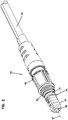
- the hardened fiber optic connector 26 can include a seal 32 that forms a radial seal within the second port 30. Additionally, the hardened fiber optic connector 26 can include a plug body 34 having a plug end 36 that is received within the second port 30. As shown at Figure 2 , the hardened fiber optic connector 26 can include a ferrule 38 that is accessible at the plug end 36.
- the plug end 36 can include a keying structure (e.g., a rail, tab, flat, non-symmetrical characteristic, etc.) that mates with a corresponding keying structure within the second port 30 to ensure that the plug end 36 is inserted into the second port 30 at a particular rotational orientation.
- the hardened fiber optic connector 26 can also include a fastening element 40 for securing the hardened fiber optic connector 26 within the second port 30.
- the fastening element 40 can have a robust configuration capable of withstanding axial loads in excess of 100 pounds.
- the fastening element 40 is rotatable relative to the plug body 34 and includes threads 42 that mate with corresponding threads 44 of the second port 30.
- the fastening element 40 of the hardened fiber optic connector has a robust configuration for mechanically coupling the hardened fiber optic connector 26 to the fiber optic adapter 22.
- the fastening element 40 is free to rotate about a central longitudinal axis of the hardened fiber optic connector 26.
- the fastening element 40 includes a coupling nut having external threads adapted to engage internal threads of the mating fiber optic adapter 22.
- the fastening element can include a coupling sleeve having internal threads that engage corresponding external threads of the mating fiber optic adapter.
- the robust coupling can be provided by a bayonet-style coupling arrangement between the fastening element and the mating fiber optic adapter.
- the interface between the hardened fiber optic connector 26 and its mating fiber optic adapter 22 is preferably environmentally sealed by a sealing arrangement configured to limit or prevent the intrusion of moisture, dust or other contaminants.
- the sealing arrangement can include one or more sealing members (e.g., O-rings, radial seals, face seals, or other gasket-type seals mounted on the plug body 34, on a shroud surrounding the plug body, or on/in the fiber optic adapter).
- the hardened fiber optic connector 26 is configured to terminate a fiber optic cable 46.
- the fiber optic cable includes an optical fiber 48 protected within a jacket 50.
- the jacket 50 can have an elongated transverse cross-section so as to have a generally "flat" configuration.
- the fiber optic cable 46 can also include one or more strength elements 52.
- the strength elements 52 are positioned on opposite sides of the optical fiber 48.
- strength elements 52 can include aramid yarn, rods made of fiber reinforced epoxy or other materials, metal members strands or braids, or other structures.
- the hardened fiber optic connector 26 includes a connector core 54 that mounts within the plug body 34.
- the hardened fiber optic connector 26 can also include a dust cap 56 that can be secured over the plug end 36 of the plug body 34 by the fastening element 40 to provide protection of the ferrule 38 when the hardened fiber optic connector 26 is not in use.
- the plug body 34 can include a main body 58 and a side cover 60.
- the hardened fiber optic connector 26 further can include a metal sleeve 62 for reinforcing the plug body 34, a shape memory sleeve 64 (e.g., a heat shrink sleeve) for providing a seal between the cable jacket 50 and the hardened fiber optic connector 26, a boot 66 for providing strain relief and bend radius protection at the interface between the fiber optic cable 46 and the back end of the hardened fiber optic connector 26, and a lanyard 68 for tethering the dust cap 56 to the hardened fiber optic connector 26.
- a metal sleeve 62 for reinforcing the plug body 34
- a shape memory sleeve 64 e.g., a heat shrink sleeve
- boot 66 for providing strain relief and bend radius protection at the interface between the fiber optic cable 46 and the back end of the hardened fiber optic connector 26
- a lanyard 68 for tethering the dust cap 56 to the hardened fiber optic connector 26.
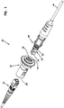
- the connector core 54 of the hardened fiber optic connector 26 includes a ferrule subassembly 70, an extension piece 72 and a cable anchor 74.
- the extension piece 72 can be mounted between the ferrule subassembly 70 and the cable anchor 74.
- the ferrule subassembly 70 attaches to a front end of the extension piece 72 by a mechanical interface such as a snap-fit connection.
- the fiber optic cable 46 can be secured to the cable anchor 74.
- the strength elements 52 and the jacket 50 can be adhesively secured within the cable anchor 74.
- the cable anchor 74 can include interlock structures 78 (e.g., teeth, tabs, ribs, etc.) that interlock with mating structures 79 on the plug body 34 to assist in axially fixing the cable anchor 74 relative to the plug body 34.
- the cable anchor 74 can connect to a rear end of the extension piece 72 by a snap-fit connection or other type of mechanical interface.
- the ferrule subassembly 70 of the connector core 54 includes the ferrule 38, a ferrule hub 80 coupled to the ferrule 38, a ferrule spring 82 and a spring retainer 84.
- the spring retainer 84 is configured to couple to the ferrule hub 80 such that the ferrule spring 82 is captured between the spring retainer 84 and the ferrule hub 80.
- the ferrule hub 80 can include tabs 86 that fit within corresponding openings 88 defined by the spring retainer 84. In certain examples, the tabs 86 fit within the openings 88 by a snap-fit connection.
- the spring retainer 84 can include an open through-slot 89 that extends through the length of the spring retainer 84 and allows the spring retainer 84 to flex open to allow the tabs 86 to snap-fit within the openings 88.
- the spring retainer 84 is configured to allow the ferrule spring 82 to be pre-compressed in an initial compressed state between the ferrule hub 80 and the spring retainer 84 (i.e., the spring holder). In this way, the ferrule spring 82 can be pre-compressed prior to loading the connector core 54 into the plug body 34. In the initial compressed state, the ferrule spring 82 is shorter than in the non-compressed state thereby allowing the pre-assembled ferrule subassembly 70 to be shorter. As described herein, shortening of the ferrule subassembly 70 by pre-compressing the ferrule spring 82 reduces the amount of excess fiber that must be pulled from the connector during the assembly process.
- the ferrule 38 and the corresponding ferrule hub 80 move together as a unit relative to the spring retainer 84.
- the ferrule 38 and the ferrune hub 80 can be referred to as a ferrule unit 91.
- the ferrule spring 82 biases the ferrule unit 91 in a forward direction relative to the spring retainer 84.
- the connection between the spring retainer 84 and the ferrule hub 80 limits the range of axial movement that is permissible between the ferrule unit 91 (i.e., the ferrule 38 and its corresponding ferrule hub 80) and the spring retainer 84.
- fiber buckling in the hardened fiber optic connector 26 can be precisely predicted, limited and controlled.
- rearward movement of the ferrule unit relative to the spring retainer 84 is limited by interference between the tabs 86 and rear ends of the openings 88.
- rearward movement of the ferrule unit relative to the spring retainer 84 can be limited by contact between a front flange 92 of the ferrule hub 80 and a forward end 94 of the spring retainer 84.
- the cable anchor 74 can be integrated directly into the extension piece 72 thereby allowing the strength elements 52 to be coupled directly to the extension piece 72 without an intermediate cable anchor piece.
- the spring retainer 84 is coupled to the ferrule hub 80 by a connection that allows the ferrule unit 91 to slide axially relative to the spring retainer 84 along a limited range of movement defined between first and second axial positions.
- the ferrule spring 82 biases the ferrule unit toward the first axial position.
- the coupling between the ferrule hub 80 and the spring retainer 84 can provide a positive stop that stops forward movement of the ferrule unit 91 relative to the spring retainer 84 at the first axial position.
- the coupling between the ferrule hub 80 and the spring retainer 84 can also provide a positive stop that stops rearward movement of the ferrule unit relative to the spring retainer 84 at the second axial position.
- the ferrule unit is rotationally keyed relative to the spring retainer 84 such that relative rotation between the ferrule unit and the spring retainer 84 is prevented.
- the first positive stop can be provided by contact between the tabs 86 and forward ends of the openings 88.
- the second positive stop can be provided by contact between the front flange 92 of the ferrule hub 80 and the forward end 94 of the spring retainer 84.
- the ferrule 38 includes a front face 96 that can be polished.
- An optical fiber stub 98 is secured within a longitudinal bore of the ferrule 38.
- the optical fiber stub 98 has a front end 100 positioned at the front face 96 of the ferrule 38 and a rear end portion 102 that projects rearwardly from a rear end of the ferrule 38.
- the rear end portion 102 of the optical fiber stub 98 can be spliced to the optical fiber 48 of the fiber optic cable 46 at a splice location 104.
- the splice location 104 can be protected within the ferrule hub 80.
- the ferrule hub 80 can include the front flange 92 that is secured to the ferrule 38 prior to splicing, and a rear hub portion 106 that can be secured to the rear end of the ferrule 38 after splicing.
- the rear hub portion 106 can include an outer shell 108 that abuts against a back side of the front flange 92.
- the outer shell 108 can include a longitudinal slot 110 that allows the outer shell 108 to be inserted over the splice location 104 after splicing.
- the outer shell 108 can define a port 112 for allowing a splice encapsulating material 113 such as adhesive to be injected into the interior of the outer shell 108 to encapsulate and protect the splice location 104.
- the tabs 86 for mechanically interfacing with the spring retainer 84 can be provided on the outer shell 108.
- the front flange 92 can be configured to mate with the interior of the plug body 34 so as to prevent relative rotation between the ferrule hub 80 and the plug body 34.
- the front flange 92 can include a plurality of flats 114 that oppose corresponding flats defined within the interior of the plug body 34 so as to prevent relative rotation between the ferrule hub 80 and the plug body 34.
- the front flange 92 can include front angled surfaces 116 that preferably seat against corresponding surfaces defined within the plug end 36 of the plug body 34 when the connector core 54 is loaded therein.
- the optical fiber 48 may be fixed relative to the hardened fiber optic connector 26 by adhesive at the cable anchor 74.
- the optical fiber 48 is prevented from pushing back into the fiber optic cable 46.
- this fiber buckling space is provided by the extension piece 72.
- the extension piece 72 is elongated and extends a majority of the length of the plug body 34.
- the ferrule subassembly 70 is configured to precisely control the range of movement of the ferrule 38 and provides positive stops for preventing the ferrule 38 from being moved rearwardly beyond a predetermined limit. Therefore, the degree of buckling that is to be accommodated within the extension piece 72 is predetermined and controlled.
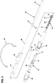
- the extension piece 72 also includes a mechanical interlock feature 120 (see Fig. 7 ) adapted to interlock or otherwise mechanically engage with the plug body 34.
- the interlock feature 120 includes a tab that fits within a corresponding opening 122 defined by the plug body 34 (see Fig. 9 ).
- the connector core 54 is preassembled prior to insertion within the plug body 34.
- the ferrule subassembly 70 is preassembled and the ferrule spring 82 is pre-compressed and retained in the initial compressed state by the spring retainer 84.
- the front angled surfaces 116 of the ferrule hub 80 abut against the corresponding surfaces provided within the plug end 36 of the plug body 34 and a secondary compression force is applied to the ferrule spring 82 as the connector core 54 is loaded into the plug body 34. This secondary compression force is sufficient to move the ferrule spring 82 from the initial compressed state to a final compressed state.
- the front angled surfaces 116 are biased firmly against the corresponding angled surfaces at the plug end 36 of the plug body 34, and the ferrule unit is forced slightly rearwardly with respect to the forward positive stop position defined by the mechanical interface between the ferrule hub 80 and the spring retainer 84.
- This secondary compression step assures that the front angled surfaces 116 are properly seated against the plug end 36 of the plug body 34, and that any tolerances in the manufacturing process have been taken up.
- the interlock feature 120 and the corresponding opening 122 are relatively positioned such that the mechanical interlock fixes the connector core 54 in the appropriate axial position relative to the plug body 34 where the ferrule spring 82 is secured and retained in the final compressed state.
- the plug body 34 generally defines the central longitudinal axis 41, and that axial movement referred to herein is made with reference to such a central longitudinal axis 41.
- the fiber optic cable 46 is initially prepared using stripping, cleaving and cleaning operations. As so prepared, an end portion of the jacket 50 is removed to expose the optical fiber 48 and end portions of the strength elements 52. After preparation of the fiber optic cable 46, the cable anchor 74 and the ferrule spring 82 can be inserted over the optical fiber 48 and the optical fiber 48 can be fusion spliced to the optical fiber stub 98 of the ferrule 38 at the splice location 104 (see Fig. 4 ).
- the outer shell 108 of the ferrule hub 80 can be laterally inserted over the splice location 104 and filled with adhesive or other encapsulating material 113 that encapsulates and protects the splice location 104 (see Fig. 5 ).
- the ferrule subassembly 70 is then assembled by sliding the ferrule spring 82 forwardly into engagement with the ferrule hub 80 and inserting the spring retainer 84 laterally over the spliced optical fiber stub 98 and optical fiber 48 via the through-slot 89 at a location behind the ferrule spring 82.
- the spring retainer 84 is then slid forwardly over the rear hub portion 106 causing the ferrule spring 82 to be axially compressed between the spring retainer 84 and the ferrule hub 80.
- the precompression of the ferrule spring 82 causes the ferrule spring 82 to be shortened and retained in an initial compressed state.
- the spring retainer 84 is moved forwardly until the tabs 86 of the ferrule hub 80 snap within the openings 88 of the spring retainer 84 such that the spring retainer 84 is effectively coupled to the ferrule hub 80.
- the ferrule spring 82 is captured and retained in the initial compressed state by the spring retainer 84 via its coupling to the ferrule hub 80.
- Figure 6 shows the preassembled ferrule subassembly 70.
- the extension piece 72 is installed between the spring retainer 84 and the cable anchor 74. Snap-fit connections may be provided between the spring retainer 84 and the front end of the extension piece 72 and between the cable anchor 74 and the rear end of the extension piece 72.
- Figure 7 shows the pre-assembled connector core 54 prior to insertion within the plug body 34. After the connector core 54 has been preassembled, the connector core is inserted axially into the plug body 34 as shown at Figure 7 .
- the connector core 54 is inserted axially into the plug body 34 until the front angled surfaces 116 at the front side of the ferrule hub 80 engage a stop structure at the inside of the plug end 36 of the plug body 34 and sufficient axial pressure is applied to the connector core 54 to move the ferrule spring 82 from the initial compressed state to a final compressed state. It will be appreciated that the interlock feature 120 of the connector core 54 snaps within the opening 122 of the plug body 34 when the connector core 54 has been inserted sufficiently within the plug body 34 for the ferrule spring 82 to move from the initial compressed state to the final compressed state.
- interlock feature 120 and the opening 122 function to secure the connector core 54 and its corresponding ferrule subassembly 70 in an axial position relative to the plug body 34 where the ferrule spring 82 is retained in the final compressed state.
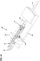
- Figures 8 and 9 show the connector core 54 fully loaded within the plug body 34.
- the assembly can be loaded into a fixture 130 having a first portion 132 that engages a forward portion of the plug body 34 and a second portion 134 that can attach (e.g., clamp) to the fiber optic cable 46.
- a spring 136 can be provided between the first and second portions 132, 134 to exert a biasing force on the second portion 134 that biases the second portion 134 in a rearward direction relative to the first portion 132. In this way, the fiber optic cable 46 is pulled rearwardly relative to the plug body 34 to cause any excess fiber length within the connector core 54 to be taken up.
- the spring 136 has a spring force that is equal to or less than a corresponding spring force of the ferrule spring 82. In this way, further compressive load is not applied to the ferrule spring 82 which would cause the ferrule spring 82 to apply tension to the optical fiber 48.
- adhesive material such as epoxy can be injected into the cable anchor 74 to secure the strength elements 52 and thus the fiber optic cable 46 at the set axial position relative to the plug body 34 where excess fiber length is not provided within the connector core 54. After curing of the adhesive, the assembly can be removed from the fixture 130 and the remainder of the assembly process can take place.
- side cover 60 of the plug body 34 can be installed on the main body 58 of the plug body 34.
- the shape memory sleeve 64 can be slid over the rear portion of the plug body 34, the heat shrink can be applied over the interface between the hardened fiber optic connector 26 and the fiber optic cable 46, the fastening element 40 can be slid over the metal sleeve 62 and the boot 66 can be installed at the rear of the plug body 34.
- components such as the boot 66, the shape memory sleeve 64, and metal sleeve 62 and the fastening element 40 can be slid over the fiber optic cable 46.
- a typical single fiber optical connector includes a ferrule having an outer cylindrical surface that functions as a reference surface when the ferrule is received within an alignment sleeve of a fiber optic adapter.
- the ferrule also defines a central axial passageway in which the optical fiber is secured.
- the optical fiber is secured in the central axial passageway with the fiber core perfectly concentric with the outer cylindrical surface of the ferrule.
- the fiber core is not typically perfectly concentric with the outer cylindrical surface.
- Fiber core eccentricity can be defined as the distance between the central longitudinal axis of the fiber core (i.e., the fiber core axis) and the central longitudinal axis defined by the ferrule outer cylindrical surface (i.e., the ferrule axis).
- the direction that the fiber core axis is offset from the ferrule axis can be referred to as the direction of core eccentricity.
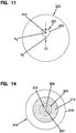
- FIG. 11 shows an end view of a ferrule 220 holding an optical fiber 221 having a fiber core 222 and a cladding 224.
- the cladding 224 typically has a different index of refraction as compared to the fiber core 222 so that light transmitted through the optical fiber 221 can be contained generally within the fiber core 222 by total internal reflection.
- the fiber core 222 is not centered relative to an outer cylindrical surface of the ferrule 220. Rather, a fiber core axis A C of the fiber core 222 is offset from a central longitudinal axis A F of the ferrule 220. In the example shown, the fiber core axis A C is offset upwardly relative to the outer cylindrical surface of the ferrule 220.
- the fiber core axis A C can be offset in any other direction relative to the outer cylindrical surface of the ferrule 220.
- the distance EC by which the fiber core axis A C is offset from the central longitudinal axis A F of the ferrule 220 corresponds to the fiber core eccentricity and is exaggerated for the purpose of illustration.
- Other fiber core eccentricities can occur due to the fiber being offset within the opening of the ferrule, even if it is centrally located in the ferrule, and/or if the core is not concentric with the cladding of the fiber.
- fiber core eccentricity Due to fiber core eccentricity, signal losses within a system can occur at the connection between two optical fibers. This is because fiber core eccentricity prevents the fiber cores of the optical fibers being optically coupled together from being perfectly co-axially aligned.
- the worst-case scenario occurs when the ferrules of two fiber optic connectors being coupled together have directions of core eccentricity that are 180 degrees out of phase with respect to each other.
- Tuning typically involves rotating the ferrule to intentionally position the direction of core eccentricity of the ferrule at a particular rotational orientation relative to one or more keyed components of the fiber optic connector.
- Example tuning techniques are disclosed at PCT Publication No. WO 02/052310 and at U.S. Patent No. 5,212,752 ).
- the hardened fiber optic connector 26 is depicted as a splice-on fiber optic connector.
- the ferrule 38 supports the optical fiber stub 98 that is spliced to the optical fiber 48 of the fiber optic cable 46.
- the front end 100 of the optical fiber stub 98 as well as the front face 96 of the ferrule 38 can be pre-processed using processing techniques such as polishing, cleaving, shaping, laser processing or other processing techniques.
- a direction of core eccentricity of the optical fiber stub 98 relative to the ferrule 38 can be determined and marked on the ferrule 38 or the front flange 92 of the ferrule hub.
- the direction of core eccentricity of the ferrule assembly can be taken into consideration. For example, tuning can be accomplished by orienting the direction of core eccentricity at a particular rotational orientation relative to the fiber optic cable 46 prior to splicing.
- the direction of core eccentricity can also be oriented at a particular orientation relative to the plug body 34 prior to splicing. In this way, after splicing, the hardened fiber optic connector 26 is tuned such that the core offset is oriented in a desired rotational orientation about the central longitudinal axis of the ferrule 38.
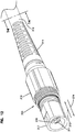
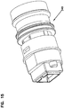
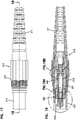
- FIGS. 12 and 13 depict another hardened fiber optic connector 310.
- the hardened fiber optic connector 310 is shown terminating a fiber optic cable 312 having an optical fiber 314 and strength members 316 surrounded by a jacket 315.
- the optical fiber 314 can include a core 307 surrounded by a cladding layer 309.
- a loose or tight buffer 305 can be provided between the optical fiber 314 and the strength members 316.
- the hardened fiber optic connector 310 includes a strain relief boot 311 that extends over the fiber optic cable 312.
- the strain relief boot 311 couples to an outer shroud 317 disposed about an inner arrangement 313 ( FIG. 13 ) including a tunable connector core 321 (see FIGS.
- a robust fastening element 319 mounts over the shroud 317 and can be rotated relative to the outer shroud 317 about a central longitudinal axis of the hardened fiber optic connector 310.
- the hardened fiber optic connector 310 directly terminates the optical fiber 314 of the fiber optic cable 312 without any intermediate splices.
- a tuning feature is integrated into the tunable connector core 321 to allow the hardened fiber optic connector 310 to be readily tuned (i.e., the fiber core eccentricity of the ferrule can be set at a desired rotational orientation relative to a keyed component of the connector such as the shroud, the plug body or both) after mounting on the optical fiber 314 to provide enhanced performance (e.g., low insertion loss).
- the outer shroud 317 has a keying feature 318 that ensures the hardened fiber optic connector 310 is loaded into a mating connecting component (e.g., a mating fiber optic adapter or a mating fiber optic connector) at a particular rotational orientation.
- FIG. 15 shows an example mating fiber optic adapter 349.
- the keying feature 318 is shown as a female structure such as a notch/slot adapted to mate with a corresponding male feature (e.g., a key, rail, projection, tab, etc.) of the mating fiber optic adapter.
- the keying feature 318 can include a male structure (e.g., one or more tabs, keys, rails, projections, etc.) that mates with a corresponding female structure of the mating fiber optic adapter.
- the robust fastening element 319 of the hardened fiber optic connector 310 is configured for mechanically coupling the hardened fiber optic connector 310 to its corresponding fiber optic adapter 349.
- the fastening element 319 mounts over the outer shroud 317 and is free to rotate about the outer shroud 317.
- the robust fastening element 319 includes coupling nut having external threads adapted to engage internal threads of the mating fiber optic adapter.
- the fastening element can include a coupling sleeve having internal threads that engage external threads of the mating fiber optic adapter.
- the robust coupling can be provided by a bayonet-style coupling arrangement between the fastening element and the mating fiber optic adapter.
- the interface between the hardened fiber optic connector 310 and its mating fiber optic adapter is preferably environmentally sealed by a sealing arrangement to limit or prevent the intrusion of moisture, dust or other contaminants.
- the sealing arrangement can include one or more sealing members (e.g., o-rings, radial seals, face seals, or other gasket-type seals) mounted on the shroud, on the connector plug body or on/in the fiber optic adapter.
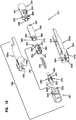
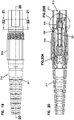
- the tunable connector core 321 of the hardened fiber optic connector 310 includes a cable anchor 320 coupled to a ferrule subassembly 381 by an elongated extension piece 340 (e.g., an extension tube).
- the ferrule subassembly 381 includes a ferrule 71 in which the optical fiber 314 is secured (e.g., an end portion of the optical fiber 314 can be secured by adhesive within the ferrule 371).
- the ferrule subassembly 381 also includes a ferrule hub 380 secured to the ferule 371, a ferrule spring 395 and a spring retainer 350 that couples to the ferrule hub 380.
- the spring retainer 350 couples to the ferrule hub 380 and the ferrule spring 395 is captured between the ferrule hub 380 and the spring retainer 350. In this way, the ferrule spring 395 is pre-compressed between the spring retainer 350 and the ferrule hub 380.
- the configuration of the ferrule subassembly 381 allows the ferrule spring 395 to be pre-compressed to an initial compressed state prior to loading the ferrule subassembly 381 into the plug body 360. As previously described, this assists in facilitating assembly operations and also allows the amount excess fiber length that must be accounted for during assembly to be reduced thereby allowing for shortening of the overall length of the fiber optic connector.
- the spring retainer 350 is configured to couple to a front end of the extension piece 340 (e.g., by a snap-fit connection or other type of mechanical connection).
- the hardened fiber optic connector 310 also includes the plug body 360 that fits over the tunable connector core 321.
- the plug body 360 includes a front plug portion 361 in which the ferule subassembly 381 is received, and a rear portion 363 that couples to the front plug portion 361.
- the rear portion 363 includes mating pieces 330a, 330b that fit over the extension piece 340 and the cable anchor 320 and that fix the front plug portion 361 relative to the cable anchor 320.
- the mating pieces 330a, 330b retain the front plug portion 361 in position over the ferrule subassembly 381.
- the outer shroud 317 fits over the plug body 360.
- the cable anchor 320 is configured to couple to a rear end of the extension piece 340 (e.g., by a snap-fit connection or other type of
- the cable anchor 320 can be filled with adhesive (e.g., epoxy) via port 421 and functions to anchor the cable strength members 316 of the fiber optic cable 312 to the tunable connector core 321 and also serves as an axial fixation location for the optical fiber 314 of the fiber optic cable 312.
- adhesive e.g., epoxy
- the optical fiber 314 can be pulled back away from ferrule subassembly 381 before applying the epoxy or before the epoxy cures to remove excess fiber length from within the tunable connector core 321.
- the extension piece 340 provides space for allowing the optical fiber 314 to buckle when the ferrule 371 is pushed back in direction 372 ( FIG. 12 ) when the hardened fiber optic connector 310 is coupled to another connector.
- the rear end of the extension piece 340 connects to the front end of the cable anchor 320 by a snap fit connection.
- tabs 398 of the cable anchor 320 snap within openings 397 of the extension piece 340 (see FIGS. 16 and 20A ).
- the extension piece 340 can include a full length longitudinal slot 373.
- the extension piece 340 can be added to the tunable cable core 321 after placement of the cable anchor 320 on the fiber optic cable 312 and after the optical fiber 314 has been secured to the ferrule 371 and the end face of the ferrule 371 has been processed (e.g., polished).
- the longitudinal slot 373 allows the extension piece 340 to be laterally inserted over the optical fiber 314.
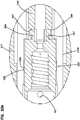
- the ferrule 371 and the ferrule hub 380 form a ferrule unit 370 that is biased forwardly relative to the spring retainer 350 by the ferrule spring 395.
- the ferrule hub 380 includes a notched circumferential flange 391 and tabs 390.
- the spring 395 is loaded into an interior 351 of the spring retainer 350 and is held therein by the ferrule unit 370.
- the ferrule spring 395 can be captured between the tabs 390 of the ferrule unit 370 and an annular spring engagement shoulder 352 of the spring retainer 350 as shown in FIG. 20B .
- the tabs 390 When assembled, the tabs 390 fit within axially elongated slots 392 of the spring retainer 350 to secure the ferrule unit 370 to the spring retainer 350 (see FIG. 20B ).
- the spring 395 biases the ferrule unit 370 in a forward direction 374 ( FIG. 12 ) and the tabs 390 can slide along the elongated slots 392 to allow relative axial movement between the ferrule unit 370 and the spring retainer 350.
- the elongated slots 392 of the spring retainer 350 are defined within flexible arms 354 that flex apart to accommodate the tabs 390 during assembly of the ferrule subassembly 381.
- the rear end of the spring retainer 350 can attach to the front end of the extension piece 340 by a snap-fit connection or other type of mechanical connection.
- tabs 396 of the extension piece 340 can snap within openings 394 of the spring retainer 350 (see FIGS. 16 and 20B ).
- the spring retainer 350 and thus the entire ferrule subassembly 381 can be rotated relative to the extension piece 340 about a central longitudinal axis of the ferrule 371 to position a core eccentricity of the optical fiber 314 within the ferrule 371 at a desired rotational position (e.g., a rotational position that aligns with a key of the hardened fiber optic connector 310 or other rotational position).
- a desired rotational position e.g., a rotational position that aligns with a key of the hardened fiber optic connector 310 or other rotational position.
- the extension piece 340 has six tabs 396 and the extension piece 340 has six corresponding openings 394 that enable the ferrule subassembly 381 to be rotated relative to the extension piece 340 to six different rotational tuning positions to tune the hardened fiber optic connector 310.
- the ferrule subassembly 381 can be initially rotated to the desired tuned rotational position and then connected to the extension piece 340 while being pre-oriented at the desired tuned rotational position. In other examples, the ferrule subassembly 381 can be initially connected to the extension piece 340 and then rotated to the desired tuned rotational position after connection to the extension piece 340.
- the front plug portion 361 fits over the ferrule subassembly 381 after the ferrule subassembly 381 has been rotated to the desired tuned position. Rails 365 within the front plug portion 361 fit within notches 401 of the notched circumferential flange 391 to further prevent relative rotation between the ferrule subassembly 381 and the front plug portion 361 once the plug body 360 has been installed over the tunable connector core 321(see FIGS. 20B and 21 ).
- Angled front surfaces 520 (see FIGS. 16 and 18A ) of the ferrule hub 380 are preferably spring biased against corresponding angled shoulder surfaces 521 (see FIG. 18A ) within the front plug portion 361. The angled shoulder surfaces 521 form a seat within the front plug portion against which the angled front surfaces 520 at the front of the ferrule hub 380 are spring biased.
- the mating pieces 330a, 330b of the rear portion 363 of the plug body 360 couple the front plug portion 361 to the cable anchor 320.
- the rear portion 363 is rotationally keyed and axially fixed relative to the cable anchor 320.
- the cable anchor 320 includes projections 323, 324 ( FIGS. 16 , 18B and 20A ) that fit within receptacles 325, 326 of the mating pieces 330a, 330b (see FIGS. 16 , 18B , and 20A ).
- the projections 323, 324 and the receptacles 325, 326 are relatively axially positioned with regard to the angled front surfaces 520 and the angled shoulder surfaces 521 such that during loading of the connector core 321 into the plug body 360, the angled front surfaces 520 of the ferrule hub 380 are forced against the angled shoulder surfaces 521 causing further compression of the ferrule spring 395 from the initial pre-compressed state to a final compressed state. In this way, mechanical tolerances are accounted for thereby ensuring that the angled front surfaces 520 seat against the angled shoulder surfaces 521.
- the front plug portion 361 is rotationally keyed and axially fixed relative to the mating pieces 330a, 330b that form the rear portion 363.
- tabs 500 FIGS. 16 and 20B
- the mating pieces 330a, 330b fit (e.g., snap-fit) within openings 502 ( FIGS. 16 and 20B ) defined in the front plug portion 363 (see FIG. 20B ).
- Rails 504 ( FIGS. 16 and 18A ) of the mating pieces 330a, 330b may fit within slots 506 ( FIGS. 16 and 18A ) defined in the front plug portion 361 (see FIG. 18A ).
- a back end 508 of the front plug portion 361 has a square transvers cross-sectional shape and fits within a square receptacle 509 of the rear portion 363 to further rotationally key and axially fix the front plug portion 361 relative to the rear portion 363 of the plug body 360.
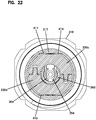
- the outer shroud 317 mounts over the plug body 360.
- the rear portion 363 of the plug body 360 is rotationally keyed relative to the outer shroud 317 by opposing flats 410, 411 of the plug body 360 and the outer shroud 317 (see FIG. 22 ).
- the longitudinal slot 373 defined through the entire length of the extension piece 340 allows it to be added, or removed, if desired.
- One advantage of making the spring retainer 350 and the extension piece 340 separate pieces is that the extension piece 340 can be added to the tunable connector core 321 after the ferrule subassembly 381 has been fully assembled, the optical fiber 314 has been secured in the ferrule 371, and the end face of the optical fiber 314 has been fully processed (e.g., polished, laser treated, laser cleaved, etc.). In this way, extra fiber length is made available to facilitate using the fiber processing equipment and enhancing fiber processing operations.
- the final fiber length within the connector is established by assembling the connector, pulling the rearwardly cable to a desired position, then anchoring the cable strength members and the cable fiber within the cable anchor with epoxy injected in the cable anchor.
- the end of the fiber optic cable 312 is first prepared by stripping the outer jacket to expose the optical fiber and strength members, and by cleaving and stripping the optical fiber as needed.
- the ferrule assembly 381 is pre-assembled thereby pre-compressing the ferrule spring 395 between the ferrule hub 380 and the spring retainer 350.
- the strain relief boot 311, the robust fastening element 319 and the outer shroud 317 can be slid over the cable jacket 315.
- the cable anchor 320 is inserted over the exposed optical fiber 314 and the strength members 316 and a portion of the jacket 315 of the fiber optic cable 312 are positioned within the cable anchor 320.
- the end of the optical fiber 314 then is secured within the ferrule 371 of the pre-assembled ferrule subassembly 381 (see FIG. 23 ).
- the end faces of the ferrule 371 and the optical fiber 314 are then polished or otherwise processed to angle, shape and/or remove imperfections from the end face of the optical fiber 314.
- a direction of core eccentricity of the fiber core relative to the ferrule 371 is determined and marked on the ferrule 371 or ferrule hub 380 to provide an indication of core eccentricity.
- the extension piece 340 is then inserted laterally over the optical fiber 314 and is mounted between the cable anchor 320 and the ferrule subassembly 381 to complete assembly of the connector core 321(see FIG. 24 ).
- the ferrule subassembly 381 is then rotated as needed relative to the extension piece 340 generally about a central longitudinal axis of the ferrule 371 to move the direction of core eccentricity to a tuned rotational position relative to the cable anchor 320. Because the cable anchor 320 is rotationally keyed relative to the plug body 360, tuning relative to the cable anchor 320 provides tuning relative to the plug body 360. After tuning, the fiber optic cable 312 can be pulled rearwardly relative to the assembled tunable connector core 321 to remove excess optical fiber from within the extension piece 340.
- adhesive can be injected into the cable anchor 320 to anchor the fiber optic cable 312 (e.g., the strength members 316 and the jacket 315) relative to the tunable connector core 321 and to provide an axial fixation location for the optical fiber 314.
- the tunable connector core 321 is loaded into the plug body 360.
- one of the mating pieces 330a, 330b is initially snapped onto the front plug portion 361.
- the front end of the connector core 321 is then inserted into front plug portion 361 through the back end of the front plug portion 361. Insertion continues causing the angled front surfaces 520 of the ferrule hub 380 to abut against the angled shoulder surfaces 521 within the front plug portion 361. Insertion continues after contact between the surfaces 520, 521 causing further compression of the ferrule spring 395.
- outer shroud 317 can be slid over the inner arrangement 313, sealing can be provided between the outer shroud 317 and the fiber optic cable 312 (e.g., with a heat shrink sleeve pre-loaded over the cable), the robust fastening element 319 can be slid over the outer shroud 317 and the strain relief boot 311 can be mounted to the rear end of the outer shroud 317.
- the fiber optic connector 310 may be a hardened connector.
- the hardened fiber optic connector 310 may also include one or more environmental seals for providing a sealed interface with an adapter port.
- the hardened fiber optic connector 310 may also include a robust fastening element 319, such as a threaded member or a bayonet style fastener, for securing the connector 310 in the adapter port.
- the tunable connector core can be used in combination with other types of plug bodies.
- the tunable connector core can be used in combination with the plug body 34 of FIG. 3 .
Landscapes
- Physics & Mathematics (AREA)
- General Physics & Mathematics (AREA)
- Optics & Photonics (AREA)
- Mechanical Coupling Of Light Guides (AREA)
Claims (19)
- Verfahren zum Zusammenbauen eines Lichtwellenleitverbinders (26), wobei der Lichtwellenleiterverbinder (26) eine Muffenunteranordnung (70) umfasst, die eine Muffe (38), eine Muffennabe (80), die an der Muffe (38) befestigt ist, einen Federhalter (84) und eine Verbinderfeder (82) umfasst, der Lichtwellenleiterverbinder (26) einen Steckerkörper (34) umfasst, in dem die Muffenunteranordnung (70) angebracht ist, der Steckerkörper (34) ein Steckerende (36) aufweist, durch das sich die Muffe (38) erstreckt, wenn die Muffenunteranordnung (70) in dem Steckerkörper (34) angebracht ist, und der Steckerkörper (34) eine zentrale Längsachse definiert, wobei das Verfahren umfasst:Vorfertigen der Muffenunteranordnung (70), sodass die Verbinderfeder (82) in einem anfänglich komprimierten Zustand zwischen der Muffennabe (80) und dem Federhalter (84) vorkomprimiert wird;Koppeln des Federhalters (84) mit der Muffennabe (80) durch eine Verbindung, die es ermöglicht, dass die Muffe (38) und die Muffennabe (80) relativ zu dem Federhalter (84) entlang eines begrenzten Bewegungsbereichs, der zwischen einer ersten und einer zweiten axialen Position definiert ist, axial zu gleiten;Einbringen der vorgefertigten Muffenunteranordnung (70) in den Steckerkörper (34) und Ausüben einer sekundären Kompressionskraft auf die Verbinderfeder (82), während die vorgefertigte Muffenunteranordnung (70) in den Steckerkörper (34) eingebracht wird, um die Verbinderfeder (82) in einen endgültigen komprimierten Zustand zu bewegen; undBefestigen der Muffenunteranordnung (70) in axialer Position relativ zu dem Steckerkörper (34), um die Verbinderfeder (82) in dem endgültigen komprimierten Zustand zu halten.
- Verfahren nach Anspruch 1, wobei die Muffenunteranordnung (70) in einen Verbinderkern (54) integriert wird, und wobei die Muffenunteranordnung (70) in axialer Position relativ zu dem Steckerkörper (34) durch mechanisches Arretieren des Verbinderkerns (54) mit dem Steckerkörper (34) befestigt wird.
- Verfahren nach Anspruch 2, wobei der Lichtwellenleiterverbinder (26) angepasst wird, an einem Ende eines Lichtwellenleiterkabels (46) befestigt zu werden, wobei das Lichtwellenleiterkabel (46) einen Lichtwellenleiter (48) umfasst, der mit der Muffe (38) gekoppelt ist, wobei der Verbinderkern (54) einen Kabelanker (74) umfasst, an dem ein Zugelement (52) des Lichtwellenleiterkabels (46) befestigt ist, und wobei vor dem Befestigen des Zugelements (52) des Kabels (46) an dem Kabelanker (74) das Kabel (46) in Bezug auf den Verbinderkern (54) zurückgezogen wird, um eine Überlänge des Lichtwellenleiters (48) aus dem Inneren des Verbinderkerns (54) zu entfernen.
- Verfahren nach Anspruch 3, wobei das Kabel (46) mit einer Kraft zurückgezogen wird, die kleiner oder gleich einer Federkraft der Verbinderfeder (82) ist.
- Verfahren nach Anspruch 3, wobei der Lichtwellenleiterverbinder (26) an einer Befestigung (130) zusammengebaut wird, und wobei die Befestigung (130) eine Befestigungsfeder (136) zum Zurückziehen des Lichtwellenleiterkabels (46) relativ zu dem Kabelkern aufweist.
- Verfahren nach Anspruch 5, wobei die Befestigungsfeder (36) eine Federkraft aufweist, die kleiner oder gleich einer Federkraft der Verbindungsfeder (82) ist.
- Verfahren nach Anspruch 3, wobei ein Lichtwellenleiterstummel (98) innerhalb der Muffe (38) befestigt wird, und wobei der Lichtwellenleiter (48) des Lichtwellenleiterkabels (46) mit dem Lichtwellenleiterstummel (98) verspleißt wird.
- Verfahren nach Anspruch 7, wobei der Lichtwellenleiterverbinder (26) vor dem Spleißen des Lichtwellenleiterstumpfes (98) mit dem Lichtwellenleiter (48) des Lichtwellenleiterkabels (46) durch Drehausrichten der Muffe (38) in einer gewünschten Drehausrichtung eingestellt wird.
- Verfahren nach Anspruch 8, ferner umfassend das Umhüllen des Spleißes mit einer mit Klebstoff gefüllten Hülle nach dem Spleißen, wobei die mit Klebstoff gefüllte Hülle einen Teil der Muffennabe (80) bildet.
- Verfahren nach Anspruch 3, wobei die Muffenunteranordnung (70) relativ zu einem Rest des Verbinderkerns (54) gedreht werden kann, um den Lichtwellenleiterverbinder (26) einzustellen.
- Lichtwellenleiterverbinder (26), umfassend:einen Steckerkörper (34) mit einem Steckerende (36);einen Verbinderkern (54), der innerhalb des Steckerkörpers (34) angebracht ist, wobei der Verbinderkern (54) eine Muffenunteranordnung (70) umfasst, die Muffenunteranordnung (70) eine Muffe (38), eine Muffennabe (80), die an der Muffe (38) angebracht ist, einen Federhalter (84) und eine Verbinderfeder (82) umfasst, wobei der Federhalter (84) mit der Muffennabe (80) durch eine Verbindung gekoppelt ist, die es ermöglicht, dass die Muffe (38) und die Muffennabe (80) relativ zu dem Federhalter (84) entlang eines begrenzten Bewegungsbereichs, der zwischen einer ersten und einer zweiten axialen Position definiert ist, axial zu gleiten, und ermöglicht, dass die Muffenunteranordnung (70) vor dem Anbringen des Verbinderkerns (54) innerhalb des Steckerkörpers mit der Verbinderfeder, die in einen anfänglichen komprimierten Zustand vorkomprimiert ist, zusammengebaut wird; undwobei der Steckerkörper (34) und der Kern derart konfiguriert sind, dass die Verbinderfeder (82) von dem anfänglich komprimierten Zustand in einen endgültig komprimierten Zustand bewegt wird, wenn der Verbinderkern in den Steckerkörper (34) eingebracht wird.
- Lichtwellenleiterverbinder nach Anspruch 11, wobei der Verbinderkern (54) mit dem Steckerkörper (34) verriegelt ist, um die Feder in dem komprimierten Endzustand zu halten.
- Lichtwellenleiterverbinder nach Anspruch 11, wobei der Verbinderkern (54) ein Verlängerungsstück (72) umfasst, und wobei die Muffenunteranordnung (70) an einem Ende des Verlängerungsstücks (72) angebracht ist.
- Lichtwellenleiterverbinder nach Anspruch 13, wobei ein Kabelanker (74) an einem gegenüberliegenden Ende des Verlängerungsstücks (72) angebracht ist.
- Lichtwellenleiterverbinder nach Anspruch 13, wobei die Muffenunteranordnung (70) in mehreren unterschiedlichen Drehpositionen relativ zu dem Verlängerungsstück (72) anbringbar ist, um ein Einstellen des Lichtwellenleiterverbinders (26) zu ermöglichen.
- Lichtwellenleiterverbinder nach Anspruch 11, wobei die Verbinderfeder (82) die Muffennabe (80) in Richtung der ersten axialen Position vorspannt und die Kopplung zwischen der Muffennabe (80) und dem Federhalter (84) einen Festanschlag bereitstellt, der eine Vorwärtsbewegung der Muffennabe (80) relativ zu dem Federhalter (84) an der ersten axialen Position stoppt.
- Lichtwellenleiterverbinder nach Anspruch 16, wobei die Kopplung zwischen der Muffennabe (80) und dem Federhalter (84) einen Festanschlag bereitstellt, der eine Rückwärtsbewegung der Muffennabe (80) relativ zu dem Federhalter (84) an der zweiten axialen Position stoppt.
- Lichtwellenleiterverbinder nach Anspruch 17, wobei der erste Festanschlag durch Kontakt zwischen Vorsprüngen (86) an der Muffennabe (80) und Vorderenden von Öffnungen (88), die durch den Federhalter (84) definiert sind, bereitgestellt wird.
- Lichtwellenleiterverbinder nach Anspruch 18, wobei der zweite Festanschlag durch Kontakt zwischen einem vorderen Flansch (92) der Muffennabe (80) und einem Vorderende (94) des Federhalters (84) bereitgestellt wird.
Applications Claiming Priority (1)
| Application Number | Priority Date | Filing Date | Title |
|---|---|---|---|
| PCT/CN2014/094391 WO2016095213A1 (en) | 2014-12-19 | 2014-12-19 | Hardened fiber optic connector with pre-compressed spring |
Publications (3)
| Publication Number | Publication Date |
|---|---|
| EP3234672A1 EP3234672A1 (de) | 2017-10-25 |
| EP3234672A4 EP3234672A4 (de) | 2018-08-22 |
| EP3234672B1 true EP3234672B1 (de) | 2021-09-08 |
Family
ID=56125673
Family Applications (1)
| Application Number | Title | Priority Date | Filing Date |
|---|---|---|---|
| EP14908248.9A Active EP3234672B1 (de) | 2014-12-19 | 2014-12-19 | Gehärteter glasfaserverbinder mit vorkomprimierter feder |
Country Status (3)
| Country | Link |
|---|---|
| US (3) | US10180541B2 (de) |
| EP (1) | EP3234672B1 (de) |
| WO (1) | WO2016095213A1 (de) |
Families Citing this family (65)
| Publication number | Priority date | Publication date | Assignee | Title |
|---|---|---|---|---|
| EP3249434B1 (de) * | 2009-09-28 | 2021-11-24 | TE Connectivity Nederland B.V. | Dichtungsgehäuse für einen verbinder an einem kabel wie z. b. einen standardisierten glasfaserverbinder |
| US10215926B2 (en) | 2011-12-14 | 2019-02-26 | Commscope Technologies Llc | Multi-fiber fiber optic connection system with flexible, insertable pins |
| EP3227736A1 (de) | 2014-12-01 | 2017-10-11 | Commscope Asia Holdings B.V. | Mehrfaseroptischer verbinder mit pivotal ausgerichteter hülse |
| EP3234672B1 (de) * | 2014-12-19 | 2021-09-08 | CommScope Telecommunications (Shanghai) Co. Ltd. | Gehärteter glasfaserverbinder mit vorkomprimierter feder |
| US9448365B2 (en) * | 2014-12-31 | 2016-09-20 | Commscope, Inc. Of North Carolina | Trunk gland adapters and related trunk gland units and methods of connecting trunk cables to fiber optic enclosures |
| EP3311207A4 (de) | 2015-06-19 | 2019-02-20 | Commscope Technologies LLC | Ferrule mit faseroptischem verbinder mit verbessertem ausrichtungsmechanismus |
| EP3317706B1 (de) * | 2015-06-30 | 2019-04-24 | Corning Optical Communications LLC | Glasfaserkabelanordnung |
| WO2017223072A1 (en) * | 2016-06-20 | 2017-12-28 | Commscope Technologies Llc | Ferrule-less fiber optic connector |
| US12271040B2 (en) | 2017-06-28 | 2025-04-08 | Corning Research & Development Corporation | Fiber optic extender ports, assemblies and methods of making the same |
| US11187859B2 (en) | 2017-06-28 | 2021-11-30 | Corning Research & Development Corporation | Fiber optic connectors and methods of making the same |
| US11668890B2 (en) | 2017-06-28 | 2023-06-06 | Corning Research & Development Corporation | Multiports and other devices having optical connection ports with securing features and methods of making the same |
| US10359577B2 (en) | 2017-06-28 | 2019-07-23 | Corning Research & Development Corporation | Multiports and optical connectors with rotationally discrete locking and keying features |
| AU2017421289B2 (en) | 2017-06-28 | 2024-04-04 | Corning Research & Development Corporation | Compact fiber optic connectors, cable assemblies and methods of making the same |
| US11300746B2 (en) | 2017-06-28 | 2022-04-12 | Corning Research & Development Corporation | Fiber optic port module inserts, assemblies and methods of making the same |
| USD1002540S1 (en) * | 2017-11-30 | 2023-10-24 | Corning Research & Development Corporation | Connector for making optical connections |
| US10324262B1 (en) * | 2017-12-07 | 2019-06-18 | Wei Min Wang | Field terminable fiber optic connectors |
| DE102018101431A1 (de) | 2018-01-23 | 2019-07-25 | Neutrik Ag | Steckverbindung |
| US11237341B2 (en) | 2018-03-06 | 2022-02-01 | Commscope Technologies Llc | Modular hardened optical fiber connector and assembly method thereof |
| WO2019194922A1 (en) | 2018-04-02 | 2019-10-10 | Senko Advanced Components, Inc | Hybrid ingress protected connector and adapter assembly |
| CN108459380B (zh) * | 2018-04-27 | 2023-09-26 | 长飞光纤光缆股份有限公司 | 一种防水型光纤连接器 |
| US10948664B2 (en) | 2018-05-08 | 2021-03-16 | Senko Advanced Components, Inc. | Ingress protected optical fiber connector having a reduced diameter with a removable retaining nut |
| US11409054B2 (en) * | 2018-05-11 | 2022-08-09 | Us Conec Ltd. | Method and apparatus for assembling uniboot fiber optic connectors |
| US11092756B2 (en) | 2018-10-10 | 2021-08-17 | Senko Advanced Components, Inc. | Ingress protected connector with an unitary orientation feature |
| US10976502B2 (en) | 2018-10-11 | 2021-04-13 | Seniko Advanced Components, Inc. | Outdoor rated assembly configured to blind mate opposing fiber optic connectors therein with a safety spring assembly |
| US11016247B2 (en) | 2018-10-11 | 2021-05-25 | Senko Advanced Components Inc | Mechanical splice protective sleeve for securing a splice area formed by splicing a plural of optical fibers |
| US10641967B1 (en) | 2018-11-16 | 2020-05-05 | Corning Research & Development Corporation | Multiport assemblies including a modular adapter support array |
| PL3887883T3 (pl) | 2018-11-29 | 2024-04-22 | Corning Research & Development Corporation | Wieloport mający porty połączeniowe z obrotowymi siłownikami |
| US10768382B2 (en) | 2018-11-29 | 2020-09-08 | Corning Research & Development Corporation | Multiport assemblies including access apertures and a release tool |
| US10761288B2 (en) * | 2018-12-06 | 2020-09-01 | Ofs Fitel, Llc | Armored fiber optic cable connector assembly |
| GB2579658A (en) * | 2018-12-11 | 2020-07-01 | Secr Defence | Fibre optic connector |
| WO2020139745A1 (en) | 2018-12-28 | 2020-07-02 | Corning Research & Development Corporation | Multiport assemblies including mounting features or dust plugs |
| US11307359B2 (en) | 2019-02-07 | 2022-04-19 | Senko Advanced Components, Inc. | Ingress protected, outdoor rated connector with integrated optical connector plug frame |
| ES2989771T3 (es) * | 2019-02-12 | 2024-11-27 | Commscope Technologies Llc | Conectores de fibra óptica y sistemas de conexión de fibra óptica |
| WO2020242847A1 (en) | 2019-05-31 | 2020-12-03 | Corning Research & Development Corporation | Multiports and other devices having optical connection ports with sliding actuators and methods of making the same |
| US11906795B2 (en) | 2019-06-19 | 2024-02-20 | Senko Advanced Components, Inc. | Fiber optic connector assembly with crimp tube subassembly and method of use |
| JP6792673B1 (ja) * | 2019-06-25 | 2020-11-25 | 日本航空電子工業株式会社 | プラグコネクタ |
| CN110542952B (zh) | 2019-07-26 | 2021-05-18 | 华为技术有限公司 | 一种光纤连接头以及光纤连接器 |
| US11294133B2 (en) | 2019-07-31 | 2022-04-05 | Corning Research & Development Corporation | Fiber optic networks using multiports and cable assemblies with cable-to-connector orientation |
| US11422318B2 (en) | 2019-08-08 | 2022-08-23 | Senko Advanced Components, Inc. | Push pull mechanism for an outdoor rated connector assembly |
| BR112022003796A2 (pt) * | 2019-08-26 | 2022-08-02 | Commscope Technologies Llc | Conectores de fibra óptica e sistemas de conexão de fibra óptica |
| US11320600B2 (en) * | 2019-09-12 | 2022-05-03 | Corning Research & Development Corporation | Fiber optic connector for hardware interiors and method of using same |
| US11487073B2 (en) | 2019-09-30 | 2022-11-01 | Corning Research & Development Corporation | Cable input devices having an integrated locking feature and assemblies using the cable input devices |
| EP3805827B1 (de) | 2019-10-07 | 2025-07-30 | Corning Research & Development Corporation | Faseroptische anschlüsse und faseroptische netzwerke mit kopplern mit variablem verhältnis |
| CN110764195B (zh) * | 2019-10-28 | 2025-05-09 | 华为技术有限公司 | 一种预连接器及通信设备 |
| US11650388B2 (en) | 2019-11-14 | 2023-05-16 | Corning Research & Development Corporation | Fiber optic networks having a self-supporting optical terminal and methods of installing the optical terminal |
| US11536921B2 (en) | 2020-02-11 | 2022-12-27 | Corning Research & Development Corporation | Fiber optic terminals having one or more loopback assemblies |
| US11585994B2 (en) * | 2020-05-20 | 2023-02-21 | Commscope Technologies Llc | Active optical cable assemblies |
| US20210382248A1 (en) | 2020-06-09 | 2021-12-09 | Senko Advanced Components, Inc. | Multiport assembly and associated compone |
| US11635576B2 (en) * | 2020-07-24 | 2023-04-25 | Senko Advanced Components, Inc. | Ferrule sub-assembly for a fiber optic connector |
| EP4204876A1 (de) * | 2020-08-31 | 2023-07-05 | Corning Research & Development Corporation | Optische steckerverbinder mit konfiguration zur verbindung mit ungleichen verbindern |
| US11604320B2 (en) | 2020-09-30 | 2023-03-14 | Corning Research & Development Corporation | Connector assemblies for telecommunication enclosures |
| WO2022094030A2 (en) | 2020-10-30 | 2022-05-05 | Corning Research & Development Corporation | Fiber optic connectors having a weatherproofing collar |
| US11686913B2 (en) | 2020-11-30 | 2023-06-27 | Corning Research & Development Corporation | Fiber optic cable assemblies and connector assemblies having a crimp ring and crimp body and methods of fabricating the same |
| US11927810B2 (en) | 2020-11-30 | 2024-03-12 | Corning Research & Development Corporation | Fiber optic adapter assemblies including a conversion housing and a release member |
| US11880076B2 (en) | 2020-11-30 | 2024-01-23 | Corning Research & Development Corporation | Fiber optic adapter assemblies including a conversion housing and a release housing |
| US11994722B2 (en) | 2020-11-30 | 2024-05-28 | Corning Research & Development Corporation | Fiber optic adapter assemblies including an adapter housing and a locking housing |
| US11762152B2 (en) | 2020-12-17 | 2023-09-19 | Senko Advanced Components, Inc. | Narrow width optical connector and optical receptacle |
| WO2022174188A1 (en) * | 2021-02-15 | 2022-08-18 | Commscope Technologies Llc | Protective packaging for splice and methods and devices for making the same |
| TWI767621B (zh) * | 2021-03-21 | 2022-06-11 | 立佳興業股份有限公司 | 防塵插座 |
| TWI759155B (zh) * | 2021-03-23 | 2022-03-21 | 劉美妙 | 光纖頭組件及其保護蓋結構 |
| US11947167B2 (en) | 2021-05-26 | 2024-04-02 | Corning Research & Development Corporation | Fiber optic terminals and tools and methods for adjusting a split ratio of a fiber optic terminal |
| USD1060249S1 (en) | 2021-08-30 | 2025-02-04 | Corning Research & Development Corporation | Multifiber connector for making optical connections |
| JPWO2023157348A1 (de) * | 2022-02-17 | 2023-08-24 | ||
| JP2024017273A (ja) * | 2022-07-27 | 2024-02-08 | 住友電気工業株式会社 | 光ファイババンドルコネクタ、及び、光ファイババンドルコネクタの製造方法 |
| EP4581413A1 (de) * | 2022-08-30 | 2025-07-09 | CommScope Technologies LLC | Faseroptische verbinder und faseroptische verbindungssysteme |
Family Cites Families (38)
| Publication number | Priority date | Publication date | Assignee | Title |
|---|---|---|---|---|
| US5212752A (en) | 1992-05-27 | 1993-05-18 | At&T Bell Laboratories | Optical fiber ferrule connector having enhanced provisions for tuning |
| US5317663A (en) | 1993-05-20 | 1994-05-31 | Adc Telecommunications, Inc. | One-piece SC adapter |
| JP3483889B2 (ja) | 1994-06-22 | 2004-01-06 | ザ ウィタカー コーポレーション | 組立性向上手段を有する光ファイバコネクタ |
| GB2359754B (en) * | 2000-03-03 | 2004-04-28 | Nmt Group Plc | Needle sheath |
| US6464402B1 (en) * | 1999-07-28 | 2002-10-15 | Fitel Usa Corp. | Optical fiber connector tuning index tool |
| US6287018B1 (en) * | 1999-07-28 | 2001-09-11 | Lucent Technologies Inc. | Tunable optical fiber connector |
| US7467896B2 (en) | 2000-05-26 | 2008-12-23 | Corning Cable Systems Llc | Fiber optic drop cables and preconnectorized assemblies |
| US6648520B2 (en) | 2001-09-28 | 2003-11-18 | Corning Cable Systems Llc | Fiber optic plug |
| US6428215B1 (en) * | 2000-12-27 | 2002-08-06 | Adc Telecommunications, Inc. | Tunable fiber optic connector and method for assembling |
| US6648521B2 (en) * | 2001-02-23 | 2003-11-18 | Fiber Systems International | Single terminus connector with preterminated fiber and fiber guide tube |
| US6663293B2 (en) * | 2001-03-16 | 2003-12-16 | Fitel Usa Corp. | Tunable optical fiber connector |
| US6579014B2 (en) | 2001-09-28 | 2003-06-17 | Corning Cable Systems Llc | Fiber optic receptacle |
| US6629782B2 (en) * | 2002-02-04 | 2003-10-07 | Adc Telecommunications, Inc. | Tuned fiber optic connector and method |
| US6789954B2 (en) * | 2002-09-13 | 2004-09-14 | Fitel Usa Corp. | Robust fiber connector |
| US6918704B2 (en) * | 2003-01-30 | 2005-07-19 | Panduit Corp. | Tunable fiber optic connector |
| US7146090B2 (en) | 2004-06-17 | 2006-12-05 | Corning Cable Systems Llc | Fiber optic cable and plug assembly |
| US20060045428A1 (en) | 2004-08-24 | 2006-03-02 | Thomas Theuerkorn | Fiber optic receptacle and plug assemblies |
| US7044650B1 (en) | 2004-10-22 | 2006-05-16 | Corning Cable Systems Llc | One-piece fiber optic receptacle having chamfer and alignment ribs |
| US7207727B2 (en) | 2004-10-22 | 2007-04-24 | Corning Cable Systems Llc | One-piece fiber optic receptacle |
| WO2006076061A2 (en) | 2005-01-12 | 2006-07-20 | Adamant Kogyo Co., Ltd. | Multi fiber optical interconnect system, with push-push type insertion/withdrawal mechanism, mt-type connector and shuttered adapter and method for using same |
| US7244066B2 (en) | 2005-02-25 | 2007-07-17 | Corning Cable Systems Llc | Fiber optic receptacle and plug assembly including alignment sleeve insert |
| US7264402B2 (en) | 2005-03-10 | 2007-09-04 | Corning Cable Systems Llc | Multi-fiber optic receptacle and plug assembly |
| US7568844B2 (en) | 2006-08-15 | 2009-08-04 | Corning Cable Systems Llc | Ruggedized fiber optic connector assembly |
| US7572065B2 (en) * | 2007-01-24 | 2009-08-11 | Adc Telecommunications, Inc. | Hardened fiber optic connector |
| GB2448935B8 (en) | 2007-05-04 | 2010-08-25 | Miniflex Ltd | Opticle fibre connector |
| US7942590B2 (en) * | 2007-12-11 | 2011-05-17 | Adc Telecommunications, Inc. | Hardened fiber optic connector and cable assembly with multiple configurations |
| EP3249434B1 (de) | 2009-09-28 | 2021-11-24 | TE Connectivity Nederland B.V. | Dichtungsgehäuse für einen verbinder an einem kabel wie z. b. einen standardisierten glasfaserverbinder |
| EP2354825B1 (de) | 2010-02-03 | 2015-07-15 | Tyco Electronics Nederland B.V. | Gehäuseanordnung für einen Verbinder, Zugentlastungselement, und Verfahren |
| EP2400351B1 (de) | 2010-06-22 | 2013-09-25 | Omega SA | Monoblock-Triebfeder für eine Uhr |
| EP2783248B1 (de) | 2011-11-23 | 2018-10-03 | ADC Telecommunications Inc. | Faseroptischer multifaserstecker |
| CN102520489B (zh) * | 2012-01-11 | 2016-04-13 | 深圳日海通讯技术股份有限公司 | 一种光纤连接器及其装配方法 |
| US9696500B2 (en) * | 2012-08-31 | 2017-07-04 | Corning Optical Communications LLC | Female hardened optical connectors for use with hybrid receptacle |
| WO2014206976A1 (en) * | 2013-06-27 | 2014-12-31 | Tyco Electronics Raychem Bvba | Fiber optic cable anchoring device for use with fiber optic connectors and methods of using the same |
| CN203688854U (zh) * | 2014-02-12 | 2014-07-02 | 泰科电子(上海)有限公司 | 光纤连接器 |
| CN203688855U (zh) * | 2014-02-14 | 2014-07-02 | 泰科电子(上海)有限公司 | 光纤连接器 |
| US10401578B2 (en) | 2014-06-23 | 2019-09-03 | CommScope Connectivity Belgium BVBA | Fiber optic connector with partial threaded portion and method of using the same |
| EP3234672B1 (de) * | 2014-12-19 | 2021-09-08 | CommScope Telecommunications (Shanghai) Co. Ltd. | Gehärteter glasfaserverbinder mit vorkomprimierter feder |
| EP3316013A4 (de) | 2015-06-23 | 2019-02-27 | ADC Telecommunications (Shanghai) Distribution Co., Ltd. | Glasfaserverbinderanordnung |
-
2014
- 2014-12-19 EP EP14908248.9A patent/EP3234672B1/de active Active
- 2014-12-19 US US15/537,259 patent/US10180541B2/en active Active
- 2014-12-19 WO PCT/CN2014/094391 patent/WO2016095213A1/en not_active Ceased
-
2018
- 2018-12-06 US US16/212,087 patent/US10451811B2/en active Active
-
2019
- 2019-09-16 US US16/571,626 patent/US10983284B2/en active Active
Also Published As
| Publication number | Publication date |
|---|---|
| US10451811B2 (en) | 2019-10-22 |
| WO2016095213A1 (en) | 2016-06-23 |
| US20200012051A1 (en) | 2020-01-09 |
| EP3234672A1 (de) | 2017-10-25 |
| US20190107677A1 (en) | 2019-04-11 |
| EP3234672A4 (de) | 2018-08-22 |
| US20170343741A1 (en) | 2017-11-30 |
| US10180541B2 (en) | 2019-01-15 |
| US10983284B2 (en) | 2021-04-20 |
Similar Documents
| Publication | Publication Date | Title |
|---|---|---|
| US10983284B2 (en) | Hardened fiber optic connector with pre-compressed spring | |
| US11573378B2 (en) | Ruggedized fiber optic connectors and connection systems | |
| US11119277B2 (en) | Splice-on fiber optic connector | |
| EP3924760B1 (de) | Faseroptische verbinder und faseroptische verbindungssysteme | |
| US20250208357A1 (en) | Fiber optic connectors and fiber optic connection systems | |
| US20160018605A1 (en) | Fiber optic connector and fiber optic cable assembly with fiber optic cable anchored to boot of fiber optic connector | |
| US20170254967A1 (en) | Optical ferrule for multi-fiber cable and hardened multi-fiber optic connector therefore | |
| US20240329312A1 (en) | Splice-on fiber optic connector assembly |
Legal Events
| Date | Code | Title | Description |
|---|---|---|---|
| STAA | Information on the status of an ep patent application or granted ep patent |
Free format text: STATUS: THE INTERNATIONAL PUBLICATION HAS BEEN MADE |
|
| PUAI | Public reference made under article 153(3) epc to a published international application that has entered the european phase |
Free format text: ORIGINAL CODE: 0009012 |
|
| STAA | Information on the status of an ep patent application or granted ep patent |
Free format text: STATUS: REQUEST FOR EXAMINATION WAS MADE |
|
| 17P | Request for examination filed |
Effective date: 20170613 |
|
| AK | Designated contracting states |
Kind code of ref document: A1 Designated state(s): AL AT BE BG CH CY CZ DE DK EE ES FI FR GB GR HR HU IE IS IT LI LT LU LV MC MK MT NL NO PL PT RO RS SE SI SK SM TR |
|
| AX | Request for extension of the european patent |
Extension state: BA ME |
|
| DAX | Request for extension of the european patent (deleted) | ||
| A4 | Supplementary search report drawn up and despatched |
Effective date: 20180725 |
|
| RIC1 | Information provided on ipc code assigned before grant |
Ipc: G02B 6/38 20060101AFI20180719BHEP |
|
| RAP1 | Party data changed (applicant data changed or rights of an application transferred) |
Owner name: COMMSCOPE CONNECTIVITY BELGIUM BVBA Owner name: COMMSCOPE ASIA HOLDINGS B.V. Owner name: COMMSCOPE TELECOMMUNICATIONS (SHANGHAI) CO. LTD. |
|
| GRAP | Despatch of communication of intention to grant a patent |
Free format text: ORIGINAL CODE: EPIDOSNIGR1 |
|
| STAA | Information on the status of an ep patent application or granted ep patent |
Free format text: STATUS: GRANT OF PATENT IS INTENDED |
|
| INTG | Intention to grant announced |
Effective date: 20210401 |
|
| GRAS | Grant fee paid |
Free format text: ORIGINAL CODE: EPIDOSNIGR3 |
|
| GRAA | (expected) grant |
Free format text: ORIGINAL CODE: 0009210 |
|
| STAA | Information on the status of an ep patent application or granted ep patent |
Free format text: STATUS: THE PATENT HAS BEEN GRANTED |
|
| AK | Designated contracting states |
Kind code of ref document: B1 Designated state(s): AL AT BE BG CH CY CZ DE DK EE ES FI FR GB GR HR HU IE IS IT LI LT LU LV MC MK MT NL NO PL PT RO RS SE SI SK SM TR |
|
| RAP3 | Party data changed (applicant data changed or rights of an application transferred) |
Owner name: COMMSCOPE ASIA HOLDINGS B.V. Owner name: COMMSCOPE CONNECTIVITY BELGIUM BVBA Owner name: COMMSCOPE TELECOMMUNICATIONS (SHANGHAI) CO. LTD. |
|
| REG | Reference to a national code |
Ref country code: GB Ref legal event code: FG4D |
|
| REG | Reference to a national code |
Ref country code: AT Ref legal event code: REF Ref document number: 1429077 Country of ref document: AT Kind code of ref document: T Effective date: 20210915 Ref country code: CH Ref legal event code: EP |
|
| REG | Reference to a national code |
Ref country code: IE Ref legal event code: FG4D |
|
| REG | Reference to a national code |
Ref country code: DE Ref legal event code: R096 Ref document number: 602014080061 Country of ref document: DE |
|
| REG | Reference to a national code |
Ref country code: LT Ref legal event code: MG9D |
|
| REG | Reference to a national code |
Ref country code: NL Ref legal event code: MP Effective date: 20210908 |
|
| PG25 | Lapsed in a contracting state [announced via postgrant information from national office to epo] |
Ref country code: HR Free format text: LAPSE BECAUSE OF FAILURE TO SUBMIT A TRANSLATION OF THE DESCRIPTION OR TO PAY THE FEE WITHIN THE PRESCRIBED TIME-LIMIT Effective date: 20210908 Ref country code: RS Free format text: LAPSE BECAUSE OF FAILURE TO SUBMIT A TRANSLATION OF THE DESCRIPTION OR TO PAY THE FEE WITHIN THE PRESCRIBED TIME-LIMIT Effective date: 20210908 Ref country code: SE Free format text: LAPSE BECAUSE OF FAILURE TO SUBMIT A TRANSLATION OF THE DESCRIPTION OR TO PAY THE FEE WITHIN THE PRESCRIBED TIME-LIMIT Effective date: 20210908 Ref country code: LT Free format text: LAPSE BECAUSE OF FAILURE TO SUBMIT A TRANSLATION OF THE DESCRIPTION OR TO PAY THE FEE WITHIN THE PRESCRIBED TIME-LIMIT Effective date: 20210908 Ref country code: BG Free format text: LAPSE BECAUSE OF FAILURE TO SUBMIT A TRANSLATION OF THE DESCRIPTION OR TO PAY THE FEE WITHIN THE PRESCRIBED TIME-LIMIT Effective date: 20211208 Ref country code: NO Free format text: LAPSE BECAUSE OF FAILURE TO SUBMIT A TRANSLATION OF THE DESCRIPTION OR TO PAY THE FEE WITHIN THE PRESCRIBED TIME-LIMIT Effective date: 20211208 Ref country code: ES Free format text: LAPSE BECAUSE OF FAILURE TO SUBMIT A TRANSLATION OF THE DESCRIPTION OR TO PAY THE FEE WITHIN THE PRESCRIBED TIME-LIMIT Effective date: 20210908 Ref country code: FI Free format text: LAPSE BECAUSE OF FAILURE TO SUBMIT A TRANSLATION OF THE DESCRIPTION OR TO PAY THE FEE WITHIN THE PRESCRIBED TIME-LIMIT Effective date: 20210908 |
|
| REG | Reference to a national code |
Ref country code: AT Ref legal event code: MK05 Ref document number: 1429077 Country of ref document: AT Kind code of ref document: T Effective date: 20210908 |
|
| PG25 | Lapsed in a contracting state [announced via postgrant information from national office to epo] |
Ref country code: LV Free format text: LAPSE BECAUSE OF FAILURE TO SUBMIT A TRANSLATION OF THE DESCRIPTION OR TO PAY THE FEE WITHIN THE PRESCRIBED TIME-LIMIT Effective date: 20210908 Ref country code: GR Free format text: LAPSE BECAUSE OF FAILURE TO SUBMIT A TRANSLATION OF THE DESCRIPTION OR TO PAY THE FEE WITHIN THE PRESCRIBED TIME-LIMIT Effective date: 20211209 |
|
| PG25 | Lapsed in a contracting state [announced via postgrant information from national office to epo] |
Ref country code: AT Free format text: LAPSE BECAUSE OF FAILURE TO SUBMIT A TRANSLATION OF THE DESCRIPTION OR TO PAY THE FEE WITHIN THE PRESCRIBED TIME-LIMIT Effective date: 20210908 |
|
| PG25 | Lapsed in a contracting state [announced via postgrant information from national office to epo] |
Ref country code: IS Free format text: LAPSE BECAUSE OF FAILURE TO SUBMIT A TRANSLATION OF THE DESCRIPTION OR TO PAY THE FEE WITHIN THE PRESCRIBED TIME-LIMIT Effective date: 20220108 Ref country code: SM Free format text: LAPSE BECAUSE OF FAILURE TO SUBMIT A TRANSLATION OF THE DESCRIPTION OR TO PAY THE FEE WITHIN THE PRESCRIBED TIME-LIMIT Effective date: 20210908 Ref country code: SK Free format text: LAPSE BECAUSE OF FAILURE TO SUBMIT A TRANSLATION OF THE DESCRIPTION OR TO PAY THE FEE WITHIN THE PRESCRIBED TIME-LIMIT Effective date: 20210908 Ref country code: RO Free format text: LAPSE BECAUSE OF FAILURE TO SUBMIT A TRANSLATION OF THE DESCRIPTION OR TO PAY THE FEE WITHIN THE PRESCRIBED TIME-LIMIT Effective date: 20210908 Ref country code: PT Free format text: LAPSE BECAUSE OF FAILURE TO SUBMIT A TRANSLATION OF THE DESCRIPTION OR TO PAY THE FEE WITHIN THE PRESCRIBED TIME-LIMIT Effective date: 20220110 Ref country code: PL Free format text: LAPSE BECAUSE OF FAILURE TO SUBMIT A TRANSLATION OF THE DESCRIPTION OR TO PAY THE FEE WITHIN THE PRESCRIBED TIME-LIMIT Effective date: 20210908 Ref country code: NL Free format text: LAPSE BECAUSE OF FAILURE TO SUBMIT A TRANSLATION OF THE DESCRIPTION OR TO PAY THE FEE WITHIN THE PRESCRIBED TIME-LIMIT Effective date: 20210908 Ref country code: EE Free format text: LAPSE BECAUSE OF FAILURE TO SUBMIT A TRANSLATION OF THE DESCRIPTION OR TO PAY THE FEE WITHIN THE PRESCRIBED TIME-LIMIT Effective date: 20210908 Ref country code: CZ Free format text: LAPSE BECAUSE OF FAILURE TO SUBMIT A TRANSLATION OF THE DESCRIPTION OR TO PAY THE FEE WITHIN THE PRESCRIBED TIME-LIMIT Effective date: 20210908 Ref country code: AL Free format text: LAPSE BECAUSE OF FAILURE TO SUBMIT A TRANSLATION OF THE DESCRIPTION OR TO PAY THE FEE WITHIN THE PRESCRIBED TIME-LIMIT Effective date: 20210908 |
|
| REG | Reference to a national code |
Ref country code: DE Ref legal event code: R097 Ref document number: 602014080061 Country of ref document: DE |
|
| PLBE | No opposition filed within time limit |
Free format text: ORIGINAL CODE: 0009261 |
|
| STAA | Information on the status of an ep patent application or granted ep patent |
Free format text: STATUS: NO OPPOSITION FILED WITHIN TIME LIMIT |
|
| PG25 | Lapsed in a contracting state [announced via postgrant information from national office to epo] |
Ref country code: MC Free format text: LAPSE BECAUSE OF FAILURE TO SUBMIT A TRANSLATION OF THE DESCRIPTION OR TO PAY THE FEE WITHIN THE PRESCRIBED TIME-LIMIT Effective date: 20210908 Ref country code: DK Free format text: LAPSE BECAUSE OF FAILURE TO SUBMIT A TRANSLATION OF THE DESCRIPTION OR TO PAY THE FEE WITHIN THE PRESCRIBED TIME-LIMIT Effective date: 20210908 |
|
| REG | Reference to a national code |
Ref country code: CH Ref legal event code: PL |
|
| 26N | No opposition filed |
Effective date: 20220609 |
|
| PG25 | Lapsed in a contracting state [announced via postgrant information from national office to epo] |
Ref country code: SI Free format text: LAPSE BECAUSE OF FAILURE TO SUBMIT A TRANSLATION OF THE DESCRIPTION OR TO PAY THE FEE WITHIN THE PRESCRIBED TIME-LIMIT Effective date: 20210908 |
|
| REG | Reference to a national code |
Ref country code: BE Ref legal event code: MM Effective date: 20211231 |
|
| PG25 | Lapsed in a contracting state [announced via postgrant information from national office to epo] |
Ref country code: LU Free format text: LAPSE BECAUSE OF NON-PAYMENT OF DUE FEES Effective date: 20211219 Ref country code: IE Free format text: LAPSE BECAUSE OF NON-PAYMENT OF DUE FEES Effective date: 20211219 |
|
| PG25 | Lapsed in a contracting state [announced via postgrant information from national office to epo] |
Ref country code: FR Free format text: LAPSE BECAUSE OF NON-PAYMENT OF DUE FEES Effective date: 20211231 Ref country code: BE Free format text: LAPSE BECAUSE OF NON-PAYMENT OF DUE FEES Effective date: 20211231 |
|
| PG25 | Lapsed in a contracting state [announced via postgrant information from national office to epo] |
Ref country code: LI Free format text: LAPSE BECAUSE OF NON-PAYMENT OF DUE FEES Effective date: 20211231 Ref country code: CH Free format text: LAPSE BECAUSE OF NON-PAYMENT OF DUE FEES Effective date: 20211231 |
|
| PG25 | Lapsed in a contracting state [announced via postgrant information from national office to epo] |
Ref country code: IT Free format text: LAPSE BECAUSE OF FAILURE TO SUBMIT A TRANSLATION OF THE DESCRIPTION OR TO PAY THE FEE WITHIN THE PRESCRIBED TIME-LIMIT Effective date: 20210908 |
|
| PG25 | Lapsed in a contracting state [announced via postgrant information from national office to epo] |
Ref country code: HU Free format text: LAPSE BECAUSE OF FAILURE TO SUBMIT A TRANSLATION OF THE DESCRIPTION OR TO PAY THE FEE WITHIN THE PRESCRIBED TIME-LIMIT; INVALID AB INITIO Effective date: 20141219 |
|
| PG25 | Lapsed in a contracting state [announced via postgrant information from national office to epo] |
Ref country code: CY Free format text: LAPSE BECAUSE OF FAILURE TO SUBMIT A TRANSLATION OF THE DESCRIPTION OR TO PAY THE FEE WITHIN THE PRESCRIBED TIME-LIMIT Effective date: 20210908 |
|
| P01 | Opt-out of the competence of the unified patent court (upc) registered |
Effective date: 20230530 |
|
| PG25 | Lapsed in a contracting state [announced via postgrant information from national office to epo] |
Ref country code: MK Free format text: LAPSE BECAUSE OF FAILURE TO SUBMIT A TRANSLATION OF THE DESCRIPTION OR TO PAY THE FEE WITHIN THE PRESCRIBED TIME-LIMIT Effective date: 20210908 |
|
| PG25 | Lapsed in a contracting state [announced via postgrant information from national office to epo] |
Ref country code: TR Free format text: LAPSE BECAUSE OF FAILURE TO SUBMIT A TRANSLATION OF THE DESCRIPTION OR TO PAY THE FEE WITHIN THE PRESCRIBED TIME-LIMIT Effective date: 20210908 |
|
| PG25 | Lapsed in a contracting state [announced via postgrant information from national office to epo] |
Ref country code: MT Free format text: LAPSE BECAUSE OF FAILURE TO SUBMIT A TRANSLATION OF THE DESCRIPTION OR TO PAY THE FEE WITHIN THE PRESCRIBED TIME-LIMIT Effective date: 20210908 |
|
| PGFP | Annual fee paid to national office [announced via postgrant information from national office to epo] |
Ref country code: GB Payment date: 20241227 Year of fee payment: 11 |
|
| PGFP | Annual fee paid to national office [announced via postgrant information from national office to epo] |
Ref country code: DE Payment date: 20241227 Year of fee payment: 11 |