EP3234665B1 - A photonic crystal fiber, a method of production thereof and a supercontinuum light source - Google Patents
A photonic crystal fiber, a method of production thereof and a supercontinuum light source Download PDFInfo
- Publication number
- EP3234665B1 EP3234665B1 EP15869379.6A EP15869379A EP3234665B1 EP 3234665 B1 EP3234665 B1 EP 3234665B1 EP 15869379 A EP15869379 A EP 15869379A EP 3234665 B1 EP3234665 B1 EP 3234665B1
- Authority
- EP
- European Patent Office
- Prior art keywords
- msf
- pcf
- inclusions
- core
- cladding region
- Prior art date
- Legal status (The legal status is an assumption and is not a legal conclusion. Google has not performed a legal analysis and makes no representation as to the accuracy of the status listed.)
- Active
Links
Images



Classifications
-
- G—PHYSICS
- G02—OPTICS
- G02B—OPTICAL ELEMENTS, SYSTEMS OR APPARATUS
- G02B6/00—Light guides; Structural details of arrangements comprising light guides and other optical elements, e.g. couplings
- G02B6/02—Optical fibres with cladding with or without a coating
- G02B6/036—Optical fibres with cladding with or without a coating core or cladding comprising multiple layers
- G02B6/03694—Multiple layers differing in properties other than the refractive index, e.g. attenuation, diffusion, stress properties
-
- C—CHEMISTRY; METALLURGY
- C03—GLASS; MINERAL OR SLAG WOOL
- C03B—MANUFACTURE, SHAPING, OR SUPPLEMENTARY PROCESSES
- C03B37/00—Manufacture or treatment of flakes, fibres, or filaments from softened glass, minerals, or slags
- C03B37/01—Manufacture of glass fibres or filaments
- C03B37/02—Manufacture of glass fibres or filaments by drawing or extruding, e.g. direct drawing of molten glass from nozzles; Cooling fins therefor
- C03B37/025—Manufacture of glass fibres or filaments by drawing or extruding, e.g. direct drawing of molten glass from nozzles; Cooling fins therefor from reheated softened tubes, rods, fibres or filaments, e.g. drawing fibres from preforms
- C03B37/027—Fibres composed of different sorts of glass, e.g. glass optical fibres
- C03B37/02781—Hollow fibres, e.g. holey fibres
-
- C—CHEMISTRY; METALLURGY
- C03—GLASS; MINERAL OR SLAG WOOL
- C03B—MANUFACTURE, SHAPING, OR SUPPLEMENTARY PROCESSES
- C03B37/00—Manufacture or treatment of flakes, fibres, or filaments from softened glass, minerals, or slags
- C03B37/01—Manufacture of glass fibres or filaments
- C03B37/02—Manufacture of glass fibres or filaments by drawing or extruding, e.g. direct drawing of molten glass from nozzles; Cooling fins therefor
- C03B37/025—Manufacture of glass fibres or filaments by drawing or extruding, e.g. direct drawing of molten glass from nozzles; Cooling fins therefor from reheated softened tubes, rods, fibres or filaments, e.g. drawing fibres from preforms
- C03B37/027—Fibres composed of different sorts of glass, e.g. glass optical fibres
- C03B37/0279—Photonic crystal fibres or microstructured optical fibres other than holey optical fibres
-
- C—CHEMISTRY; METALLURGY
- C03—GLASS; MINERAL OR SLAG WOOL
- C03B—MANUFACTURE, SHAPING, OR SUPPLEMENTARY PROCESSES
- C03B37/00—Manufacture or treatment of flakes, fibres, or filaments from softened glass, minerals, or slags
- C03B37/10—Non-chemical treatment
-
- C—CHEMISTRY; METALLURGY
- C03—GLASS; MINERAL OR SLAG WOOL
- C03C—CHEMICAL COMPOSITION OF GLASSES, GLAZES OR VITREOUS ENAMELS; SURFACE TREATMENT OF GLASS; SURFACE TREATMENT OF FIBRES OR FILAMENTS MADE FROM GLASS, MINERALS OR SLAGS; JOINING GLASS TO GLASS OR OTHER MATERIALS
- C03C13/00—Fibre or filament compositions
- C03C13/04—Fibre optics, e.g. core and clad fibre compositions
- C03C13/045—Silica-containing oxide glass compositions
-
- C—CHEMISTRY; METALLURGY
- C03—GLASS; MINERAL OR SLAG WOOL
- C03C—CHEMICAL COMPOSITION OF GLASSES, GLAZES OR VITREOUS ENAMELS; SURFACE TREATMENT OF GLASS; SURFACE TREATMENT OF FIBRES OR FILAMENTS MADE FROM GLASS, MINERALS OR SLAGS; JOINING GLASS TO GLASS OR OTHER MATERIALS
- C03C13/00—Fibre or filament compositions
- C03C13/04—Fibre optics, e.g. core and clad fibre compositions
- C03C13/045—Silica-containing oxide glass compositions
- C03C13/046—Multicomponent glass compositions
-
- C—CHEMISTRY; METALLURGY
- C03—GLASS; MINERAL OR SLAG WOOL
- C03C—CHEMICAL COMPOSITION OF GLASSES, GLAZES OR VITREOUS ENAMELS; SURFACE TREATMENT OF GLASS; SURFACE TREATMENT OF FIBRES OR FILAMENTS MADE FROM GLASS, MINERALS OR SLAGS; JOINING GLASS TO GLASS OR OTHER MATERIALS
- C03C25/00—Surface treatment of fibres or filaments made from glass, minerals or slags
- C03C25/10—Coating
- C03C25/104—Coating to obtain optical fibres
- C03C25/106—Single coatings
- C03C25/1061—Inorganic coatings
-
- C—CHEMISTRY; METALLURGY
- C03—GLASS; MINERAL OR SLAG WOOL
- C03C—CHEMICAL COMPOSITION OF GLASSES, GLAZES OR VITREOUS ENAMELS; SURFACE TREATMENT OF GLASS; SURFACE TREATMENT OF FIBRES OR FILAMENTS MADE FROM GLASS, MINERALS OR SLAGS; JOINING GLASS TO GLASS OR OTHER MATERIALS
- C03C25/00—Surface treatment of fibres or filaments made from glass, minerals or slags
- C03C25/10—Coating
- C03C25/104—Coating to obtain optical fibres
- C03C25/106—Single coatings
- C03C25/1061—Inorganic coatings
- C03C25/1062—Carbon
-
- C—CHEMISTRY; METALLURGY
- C03—GLASS; MINERAL OR SLAG WOOL
- C03C—CHEMICAL COMPOSITION OF GLASSES, GLAZES OR VITREOUS ENAMELS; SURFACE TREATMENT OF GLASS; SURFACE TREATMENT OF FIBRES OR FILAMENTS MADE FROM GLASS, MINERALS OR SLAGS; JOINING GLASS TO GLASS OR OTHER MATERIALS
- C03C25/00—Surface treatment of fibres or filaments made from glass, minerals or slags
- C03C25/10—Coating
- C03C25/104—Coating to obtain optical fibres
- C03C25/1065—Multiple coatings
- C03C25/1068—Inorganic coatings
-
- C—CHEMISTRY; METALLURGY
- C03—GLASS; MINERAL OR SLAG WOOL
- C03C—CHEMICAL COMPOSITION OF GLASSES, GLAZES OR VITREOUS ENAMELS; SURFACE TREATMENT OF GLASS; SURFACE TREATMENT OF FIBRES OR FILAMENTS MADE FROM GLASS, MINERALS OR SLAGS; JOINING GLASS TO GLASS OR OTHER MATERIALS
- C03C25/00—Surface treatment of fibres or filaments made from glass, minerals or slags
- C03C25/60—Surface treatment of fibres or filaments made from glass, minerals or slags by diffusing ions or metals into the surface
- C03C25/607—Surface treatment of fibres or filaments made from glass, minerals or slags by diffusing ions or metals into the surface in the gaseous phase
-
- G—PHYSICS
- G02—OPTICS
- G02B—OPTICAL ELEMENTS, SYSTEMS OR APPARATUS
- G02B6/00—Light guides; Structural details of arrangements comprising light guides and other optical elements, e.g. couplings
- G02B6/02—Optical fibres with cladding with or without a coating
- G02B6/02295—Microstructured optical fibre
- G02B6/02314—Plurality of longitudinal structures extending along optical fibre axis, e.g. holes
- G02B6/02342—Plurality of longitudinal structures extending along optical fibre axis, e.g. holes characterised by cladding features, i.e. light confining region
- G02B6/02347—Longitudinal structures arranged to form a regular periodic lattice, e.g. triangular, square, honeycomb unit cell repeated throughout cladding
-
- G—PHYSICS
- G02—OPTICS
- G02B—OPTICAL ELEMENTS, SYSTEMS OR APPARATUS
- G02B6/00—Light guides; Structural details of arrangements comprising light guides and other optical elements, e.g. couplings
- G02B6/02—Optical fibres with cladding with or without a coating
- G02B6/02295—Microstructured optical fibre
- G02B6/02314—Plurality of longitudinal structures extending along optical fibre axis, e.g. holes
- G02B6/02342—Plurality of longitudinal structures extending along optical fibre axis, e.g. holes characterised by cladding features, i.e. light confining region
- G02B6/02357—Property of longitudinal structures or background material varies radially and/or azimuthally in the cladding, e.g. size, spacing, periodicity, shape, refractive index, graded index, quasiperiodic, quasicrystals
-
- G—PHYSICS
- G02—OPTICS
- G02B—OPTICAL ELEMENTS, SYSTEMS OR APPARATUS
- G02B6/00—Light guides; Structural details of arrangements comprising light guides and other optical elements, e.g. couplings
- G02B6/02—Optical fibres with cladding with or without a coating
- G02B6/02295—Microstructured optical fibre
- G02B6/02314—Plurality of longitudinal structures extending along optical fibre axis, e.g. holes
- G02B6/02342—Plurality of longitudinal structures extending along optical fibre axis, e.g. holes characterised by cladding features, i.e. light confining region
- G02B6/02361—Longitudinal structures forming multiple layers around the core, e.g. arranged in multiple rings with each ring having longitudinal elements at substantially the same radial distance from the core, having rotational symmetry about the fibre axis
-
- G—PHYSICS
- G02—OPTICS
- G02B—OPTICAL ELEMENTS, SYSTEMS OR APPARATUS
- G02B6/00—Light guides; Structural details of arrangements comprising light guides and other optical elements, e.g. couplings
- G02B6/02—Optical fibres with cladding with or without a coating
- G02B6/02395—Glass optical fibre with a protective coating, e.g. two layer polymer coating deposited directly on a silica cladding surface during fibre manufacture
-
- G—PHYSICS
- G02—OPTICS
- G02B—OPTICAL ELEMENTS, SYSTEMS OR APPARATUS
- G02B6/00—Light guides; Structural details of arrangements comprising light guides and other optical elements, e.g. couplings
- G02B6/10—Light guides; Structural details of arrangements comprising light guides and other optical elements, e.g. couplings of the optical waveguide type
- G02B6/14—Mode converters
-
- G—PHYSICS
- G02—OPTICS
- G02F—OPTICAL DEVICES OR ARRANGEMENTS FOR THE CONTROL OF LIGHT BY MODIFICATION OF THE OPTICAL PROPERTIES OF THE MEDIA OF THE ELEMENTS INVOLVED THEREIN; NON-LINEAR OPTICS; FREQUENCY-CHANGING OF LIGHT; OPTICAL LOGIC ELEMENTS; OPTICAL ANALOGUE/DIGITAL CONVERTERS
- G02F1/00—Devices or arrangements for the control of the intensity, colour, phase, polarisation or direction of light arriving from an independent light source, e.g. switching, gating or modulating; Non-linear optics
- G02F1/35—Non-linear optics
- G02F1/365—Non-linear optics in an optical waveguide structure
-
- C—CHEMISTRY; METALLURGY
- C03—GLASS; MINERAL OR SLAG WOOL
- C03B—MANUFACTURE, SHAPING, OR SUPPLEMENTARY PROCESSES
- C03B2201/00—Type of glass produced
- C03B2201/02—Pure silica glass, e.g. pure fused quartz
-
- C—CHEMISTRY; METALLURGY
- C03—GLASS; MINERAL OR SLAG WOOL
- C03B—MANUFACTURE, SHAPING, OR SUPPLEMENTARY PROCESSES
- C03B2201/00—Type of glass produced
- C03B2201/06—Doped silica-based glasses
- C03B2201/08—Doped silica-based glasses doped with boron or fluorine or other refractive index decreasing dopant
- C03B2201/12—Doped silica-based glasses doped with boron or fluorine or other refractive index decreasing dopant doped with fluorine
-
- C—CHEMISTRY; METALLURGY
- C03—GLASS; MINERAL OR SLAG WOOL
- C03B—MANUFACTURE, SHAPING, OR SUPPLEMENTARY PROCESSES
- C03B2201/00—Type of glass produced
- C03B2201/06—Doped silica-based glasses
- C03B2201/20—Doped silica-based glasses doped with non-metals other than boron or fluorine
- C03B2201/21—Doped silica-based glasses doped with non-metals other than boron or fluorine doped with molecular hydrogen
-
- C—CHEMISTRY; METALLURGY
- C03—GLASS; MINERAL OR SLAG WOOL
- C03B—MANUFACTURE, SHAPING, OR SUPPLEMENTARY PROCESSES
- C03B2201/00—Type of glass produced
- C03B2201/06—Doped silica-based glasses
- C03B2201/20—Doped silica-based glasses doped with non-metals other than boron or fluorine
- C03B2201/22—Doped silica-based glasses doped with non-metals other than boron or fluorine doped with deuterium
-
- C—CHEMISTRY; METALLURGY
- C03—GLASS; MINERAL OR SLAG WOOL
- C03B—MANUFACTURE, SHAPING, OR SUPPLEMENTARY PROCESSES
- C03B2203/00—Fibre product details, e.g. structure, shape
- C03B2203/10—Internal structure or shape details
- C03B2203/14—Non-solid, i.e. hollow products, e.g. hollow clad or with core-clad interface
-
- C—CHEMISTRY; METALLURGY
- C03—GLASS; MINERAL OR SLAG WOOL
- C03B—MANUFACTURE, SHAPING, OR SUPPLEMENTARY PROCESSES
- C03B2203/00—Fibre product details, e.g. structure, shape
- C03B2203/10—Internal structure or shape details
- C03B2203/22—Radial profile of refractive index, composition or softening point
- C03B2203/23—Double or multiple optical cladding profiles
-
- C—CHEMISTRY; METALLURGY
- C03—GLASS; MINERAL OR SLAG WOOL
- C03B—MANUFACTURE, SHAPING, OR SUPPLEMENTARY PROCESSES
- C03B2203/00—Fibre product details, e.g. structure, shape
- C03B2203/42—Photonic crystal fibres, e.g. fibres using the photonic bandgap PBG effect, microstructured or holey optical fibres
-
- C—CHEMISTRY; METALLURGY
- C03—GLASS; MINERAL OR SLAG WOOL
- C03C—CHEMICAL COMPOSITION OF GLASSES, GLAZES OR VITREOUS ENAMELS; SURFACE TREATMENT OF GLASS; SURFACE TREATMENT OF FIBRES OR FILAMENTS MADE FROM GLASS, MINERALS OR SLAGS; JOINING GLASS TO GLASS OR OTHER MATERIALS
- C03C2201/00—Glass compositions
- C03C2201/02—Pure silica glass, e.g. pure fused quartz
-
- C—CHEMISTRY; METALLURGY
- C03—GLASS; MINERAL OR SLAG WOOL
- C03C—CHEMICAL COMPOSITION OF GLASSES, GLAZES OR VITREOUS ENAMELS; SURFACE TREATMENT OF GLASS; SURFACE TREATMENT OF FIBRES OR FILAMENTS MADE FROM GLASS, MINERALS OR SLAGS; JOINING GLASS TO GLASS OR OTHER MATERIALS
- C03C2201/00—Glass compositions
- C03C2201/06—Doped silica-based glasses
- C03C2201/20—Doped silica-based glasses containing non-metals other than boron or halide
- C03C2201/21—Doped silica-based glasses containing non-metals other than boron or halide containing molecular hydrogen
-
- C—CHEMISTRY; METALLURGY
- C03—GLASS; MINERAL OR SLAG WOOL
- C03C—CHEMICAL COMPOSITION OF GLASSES, GLAZES OR VITREOUS ENAMELS; SURFACE TREATMENT OF GLASS; SURFACE TREATMENT OF FIBRES OR FILAMENTS MADE FROM GLASS, MINERALS OR SLAGS; JOINING GLASS TO GLASS OR OTHER MATERIALS
- C03C2201/00—Glass compositions
- C03C2201/06—Doped silica-based glasses
- C03C2201/20—Doped silica-based glasses containing non-metals other than boron or halide
- C03C2201/22—Doped silica-based glasses containing non-metals other than boron or halide containing deuterium
-
- G—PHYSICS
- G02—OPTICS
- G02B—OPTICAL ELEMENTS, SYSTEMS OR APPARATUS
- G02B6/00—Light guides; Structural details of arrangements comprising light guides and other optical elements, e.g. couplings
- G02B6/02—Optical fibres with cladding with or without a coating
- G02B6/02295—Microstructured optical fibre
- G02B6/02314—Plurality of longitudinal structures extending along optical fibre axis, e.g. holes
- G02B6/02342—Plurality of longitudinal structures extending along optical fibre axis, e.g. holes characterised by cladding features, i.e. light confining region
- G02B6/02366—Single ring of structures, e.g. "air clad"
-
- G—PHYSICS
- G02—OPTICS
- G02F—OPTICAL DEVICES OR ARRANGEMENTS FOR THE CONTROL OF LIGHT BY MODIFICATION OF THE OPTICAL PROPERTIES OF THE MEDIA OF THE ELEMENTS INVOLVED THEREIN; NON-LINEAR OPTICS; FREQUENCY-CHANGING OF LIGHT; OPTICAL LOGIC ELEMENTS; OPTICAL ANALOGUE/DIGITAL CONVERTERS
- G02F1/00—Devices or arrangements for the control of the intensity, colour, phase, polarisation or direction of light arriving from an independent light source, e.g. switching, gating or modulating; Non-linear optics
- G02F1/35—Non-linear optics
- G02F1/3528—Non-linear optics for producing a supercontinuum
Definitions
- the invention relates to a photonic crystal fiber (PCF), a method of producing the PCF and a supercontinuum light source comprising such PCF, microstructured optical fiber and to a source of optical supercontinuum radiation.
- PCF photonic crystal fiber
- a supercontinuum light source comprising such PCF, microstructured optical fiber and to a source of optical supercontinuum radiation.
- Photonic crystal fibers in the following referred to as PCF or microstructured optical fibers (MSF), are fibers having a core surrounded by a cladding region having a plurality of inclusions (sometimes called cladding features or microstructures) arranged in a background material, typically in a regular array.
- the inclusion may be gas, liquid, or solid inclusion.
- the inclusions could be void, but in practice the voids will normally comprise some gas molecules Fibers of this types are well known in the art and are for example described in US2012195554 , US8406594 , US2011116283 and US2012195554
- the microstructured fiber may for example be of silica glass. Other materials may be added to the silica glass in order to alter the refractive index thereof or to provide effects, such as amplification of light, sensitivity, etc.
- the center-to-center spacing between the cladding inclusions is defined as the pitch ( ⁇ ).
- the PCFs are usually at least partly characterized by the size of the core and the ratio of the size of the inclusions to their spacing or pitch ( ⁇ ).
- ZDW zero dispersion wavelength
- Photonic crystal fibers are in general suitable for use in high power light sources. Guiding of relatively high powers in an optical fiber may have relevance for several commercial applications such as such as guiding of surgical and/or therapeutic light, optical sensing, and materials processing. Among such applications is transport of optical energy and utilizing of non-linear effects in the fiber which are commonly more pronounced with higher optical power inside the fiber.
- the optical power may be continuous wave (CW), pulsed or a mixture thereof.
- High optical power inside a fiber may be particularly pronounced with pulsed light where a high peak power may be obtainable even while having a relatively modest average power.
- the damage threshold of the fiber is the damage threshold of the fiber.
- the PCF is applied for supercontinuum generation where high power light is fed to the PCF via a launching end (sometimes called an input end) of the PCF
- launching end sometimes called an input end
- the PCF degrades over time in dependence on the peak power of the fed light.
- a fiber section adjacent to or close to the launching end is more exposed to degradation than longer from the launching end.
- US8145023 describes a method of alleviating the degradation caused by the high power light fed to the PCF by loading the core material and optionally the cladding material with hydrogen and/or deuterium. This loading was found to result in some increase in the lifetime of the fiber. In US2011116283 the method was further improved by subjecting the PCF to an annealing and/or to a high power irradiation after the hydrogen and/or deuterium loading.
- US 6661957 B1 describes how a diffusion barrier attached to the cladding layer prevents significant diffusion of a Raman active gas out of the holes in a holey fiber or photonic band gap fiber.
- WO 2005/010583 A1 describes an optical fiber including a glass fiber having a glass core and a cladding which contains voids spaced apart from the core. The voids act as trapping sites for ingressing molecules from the surrounding environment, thereby reducing the effect of such molecules on the fiber's light transmission properties.
- An object of the present invention is to provide a PCF, equivalently MSF, suitable for supercontinuum generation, which PCF is very resistant against degradation.
- a further object is to provide a supercontinuum light source comprising a PCF with a high resistance against degradation as well as preferred applications of such supercontinuum light source.
- Photonic Crystal Fiber (PCF), equivalently microstructured optical fiber (MSF), of the invention has a longitudinal axis and comprises a core extending along the length of the longitudinal axis and a cladding region surrounding the core. At least the cladding region comprises a plurality of microstructures in the form of inclusions extending along the longitudinal axis of the PCF in at least a microstructured length section.
- the PCF has a degradation resistant length section which may be the entire length of the PCF or merely a length section thereof.
- degradation resistant length section is used to indicate that the fiber length section has a very high degradation resistance over time relative to other prior art fiber length sections.
- the PCF in at least the degradation resistant length section of said microstructured length section comprises hydrogen and/or deuterium and the PCF in at least the degradation resistant length section further comprises a main coating surrounding the cladding region, which main coating is hermetic for said hydrogen and/or deuterium at a temperature below T h , wherein T h is at least about 50 °C.
- T h is at least about the maximal expected temperature of the PCF when in use. Thereby a minimum of the hydrogen and/or deuterium is diffused out of the fiber over time and/or during use.
- T h is as follows: 50 °C ⁇ Th ⁇ 250 °C. In an embodiment T h is up to about 150 °C.
- the term 'hermetic' is herein used to mean that any diffusion of the hydrogen atoms and/or deuterium atoms through the coating which is less than about 1 % per day measured e.g. using Raman spectroscopy and at the relevant temperature at atmosphere condition (i.e. the fiber is arranged at 1 bar in air) or by IR spectroscopy by measuring the absorption line of H2 (or D2) at around 1240 nm or around 1870 nm for H2 or around 1715 nm for D2.
- the hermetic coating allows a diffusion of less than 0.5 %, such as less than about 0.1 % per day, such as less than about 0.01% per day.
- inclusions means inclusions in a background material, wherein an inclusion has another refractive index than that of the background material surrounding it.
- the inclusions may e.g. be gas inclusions, such as of air, nitrogen or any other gas; solid inclusions, such of another glass type than the background material and/or a doped material (index changing materials such as F, Ge, P, B,), a vacuum inclusion or any combinations thereof.
- gas inclusions may act as hydrogen/and or deuterium depots where the inclusions are closed on either side of the degradation resistant length section.
- radial distance means distance determined in radial direction from the longitudinal axis.
- the cladding region may have a homogeneous background material or it may have several regions with respective background materials which differ from each other.
- the background material is advantageously silica optionally doped
- the cladding region comprises an inner cladding region and an outer cladding region surrounding the inner cladding region wherein the background material of the inner cladding region differs from the background material of the outer cladding region e.g. as described in US8600207 .
- the cladding region comprises an inner cladding region and an outer cladding region surrounding the inner cladding region wherein the background material of the inner cladding region has the same refractive index as the background material of the outer cladding region.
- the inner cladding region and the outer cladding region have the same background material.
- the difference between the inner and the outer cladding region is for example a difference of the size, type and/or number of inclusions.
- the cladding region confines the light to the core, and advantageously the inclusions are arranged to influence the average refractive index which results in the confining of the light.
- the inclusions should be relatively close to the core, and preferably at least some of the inclusions should have a center-to-center distance to the core of up to about 50 ⁇ m, preferably up to about 40 ⁇ m, such as up to about 30 ⁇ m, such as up to about 15 ⁇ m.
- the amount of hydrogen and/or deuterium is not included as part of the material.
- the background material of the cladding region and the core material is substantially pure silica.
- the background material of the cladding region and the core material is silica doped with fluoride.
- the content of hydrogen and/or deuterium in the form of H2 or D2 in the core of at least the degradation resistant length section comprises at least about 0.001 ppm, such as at least about 0.01 ppm, such as from about 0.1 to about 10000 ppm.
- the amount of hydrogen and/or deuterium can e.g. be determined by determining the resulting absorption at respective hydrogen or deuterium absorption peaks as explained above.
- the degradation resistant length section may have any length.
- the degradation resistant length section extends from an end of the PCF.
- the degradation resistant length section extends from the launching end of the PCF.
- the launching end is the end which is optically coupled or is adapted to be coupled to a pump laser for feeding light to the PCF.
- the degradation resistant length section can be positioned where the high power light is to be fed to the PCF. It has been observed that the major damage to the prior art PFC occurs close to a launching end of the PCF. By ensuring a sufficient load of hydrogen and/or deuterium at the launching end of the PCF, the PCF has a much increased resistance against damage due to loading stress, which further prolongs the lifetime for the whole PCF.
- ring of inclusions refers to the cladding inclusions typically having substantially equal distance to the core and being aligned in a circular or non-circular ring surrounding the core.
- a ring of inclusions is not fully circular, but rather shaped with a number of soft angles, such as in a hexagonal shape.
- all the inclusions of a ring of inclusions are of substantially the same size and preferably of same material.
- the plurality of inclusions in the cladding region are arranged in a pattern comprising at least two rings of inclusions surrounding the core.
- the center-to-center distance (also referred to as the pitch A) is advantageously at least about 1 ⁇ m, such as from about 1.5 ⁇ m to about 5 ⁇ m or larger.
- the inclusion diameter (d) is advantageously at least about: 0.5 ⁇ m, such as from about 1 ⁇ m to about 3 ⁇ m.
- the relative diameter/pitch d/ ⁇ is preferably from about 0.4 to about 0.85.
- the inclusion diameter or the diameter of the inclusion is also referred to as the characteristic diameter of the inclusion.
- the phrase "characteristic diameter" is a measure of the size of an inclusion (also called a cladding feature). If the cladding feature is circular, the characteristic diameter is the diameter of the circle of the cladding feature. In case the cladding feature is not circular, the characteristic diameter is in an embodiment determined as the average of the maximum and the minimum extent of the cladding feature or in another embodiment the characteristic diameter is the diameter of a circle having an area corresponding to a calculated or measured area of the cladding feature in question.
- the inclusions may have equal or different diameters and the inclusion diameter of the respective inclusions may as mentioned be equal or differ along the length of the fiber.
- PA 2014 70146 discloses preferred embodiments of the PCF of the invention with the difference that at least a length section of the PCF disclosed in PA 2014 70146 is modified to be or comprise a degradation resistant length section comprising hydrogen and/or deuterium and a hermetic coating as described herein.
- the inclusion diameter (d) of the respective inclusions is equal along the length of the fiber. In an embodiment the inclusion diameter (d) of the respective inclusions differs along at least a section of the length of the fiber - e.g. along a tapered section.
- inclusions may - as indicated above - in principle comprise or consist of any kind of material, usually comprising material having a different refractive index than the background material in which the respective inclusion is embedded or comprised. Examples of suitable inclusion materials are disclosed above.
- the inclusions comprise gas inclusions, such as air holes - e.g. air holes with air at low or at surrounding (atmosphere pressure).
- gas inclusions are closed on both sides of said degradation resistant length section.
- the degradation resistant length section is the whole length of the PCF optionally with exception of closed ends of the PCF.
- the ends of the PCF may for example be closed by collapsing the PCF in a short end section or by fusing a short solid silica length section to the respective ends.
- the closed ends each have a relatively short length along the length of the PCF in order to reduce any risk of losing light.
- the closed ends each have a length of the PCF of up to about 3 mm, such as up to about 2 mm, such as up to about 1 mm, such as up to about 0.5 mm, such as up to about 0.3 mm, such as up to about 0.2 mm.
- the plurality of inclusions in the cladding region of at least the degradation resistant length section comprise an inner cladding region comprising inner inclusions and an outer cladding region comprising outer inclusions.
- This embodiment has found to provide a very good PCF for supercontinuum generation.
- the inner inclusions are larger than the outer inclusions.
- the inner inclusion has a diameter d inner which is at least about 15 % larger than a diameter d outer of the outer inclusions, such as at least about 20%, such as at least about 25%, such as at least about 30 %.
- d inner is preferably at least about 1.5 ⁇ m, such as from about 1.8 to about 4 ⁇ m, such as from about 2 to about 2.5 ⁇ m.
- d outer is preferably at less than about 2.5 ⁇ m, such as from about 0.8 to about 2 ⁇ m, such as from about 1 to about 1.8 ⁇ .
- the background material of the inner cladding region and the background material of the outer cladding region are identical and optionally are also identical with the core material.
- the background material of the inner cladding region and the background material of the outer cladding region and optionally the core material are substantially pure silica or optionally silica doped with fluorine.
- the outer cladding region comprises at least three rings of outer inclusions.
- DK PA 2014 70146 for example as described and shown in figures 2a and 3a of DK PA 2014 70146 wherein the PCF is modified to be or comprises a degradation resistant length section comprising hydrogen and/or deuterium and a hermetic coating as described herein.
- the cladding region in at least the degradation resistant length section comprises an inner cladding region comprising the inclusions and an outer cladding region surrounding the inner cladding region wherein the radial distance between an outermost inclusion of the inner cladding region and the main coating is at least about 10 ⁇ m.
- the material between the inner cladding region and the main coating forms a reservoir for hydrogen and/or deuterium.
- a large area may form a reservoir for hydrogen and/or deuterium which gradually can diffuse to the core as the hydrogen and/or deuterium is consumed in the core, thereby maintaining a relatively stable and sufficient concentration of hydrogen and/or deuterium in the core.
- the material between the inner cladding region and the main coating forms a reservoir for hydrogen and/or deuterium e.g. the reservoir for hydrogen is porous silica.
- the reservoir for hydrogen between the inner cladding region and the main coating comprises glass or plastic with a higher adsorption capacity for hydrogen and/or deuterium than the material of the inner cladding region background material.
- the core may in principle have any size.
- the larger the core the higher power can be fed to the PCF, however, if the core becomes too large it may become difficult to broaden the band width to a desired degree.
- the core has a diameter of at least about 1 ⁇ m and preferably at least about 2 ⁇ m. Thereby it is ensured that the optical fiber is able to withstand the power necessary for supercontinuum generation and/or high power in general.
- the core in at least the degradation resistant length section has a core diameter of about 10 ⁇ m or less, such as about 8 ⁇ m or less, such as about 6 ⁇ m or less. In an embodiment the core diameter is in the range of from about 3 ⁇ m, such as about 3 ⁇ m to about 7 ⁇ m.
- the core is defined by the inclusions - i.e. the inclusions surrounding the core have a different refractive index which thereby forms the core.
- the PCF is made from silica optionally doped as described above.
- the material of the core and/or of the cladding region is doped.
- an innermost inclusion in at least the degradation resistant length section has a center-to-center distance to the core of less than about 50 ⁇ m, preferably less than about 40 ⁇ m, such as less than about 30 ⁇ m, such as less than about 10 ⁇ m.
- the core is a solid core.
- solid core means that the core is of solid material substantially without gas comprising voids.
- the core is a microstructured core.
- the core is a solid core optionally comprising solid microstructures.
- the core is in an embodiment substantially pure silica.
- the zero dispersion wavelength (ZDW) of the fiber may be tailored.
- the PCF has anomalous dispersion for at least one wavelength between 1000 nm and 1100 nm.
- the PCF has an anomalous dispersion at about 1030 nm or 1064 nm.
- the core of the PCF is single mode at the pump wavelength.
- the core of the PCF is spatially single mode at 1064 nm.
- Spatially single mode means that higher order modes have a loss which is at least 19.3 dB higher than the fundamental mode for a fiber with a length of 2 m. This can e.g. be measured using the SA 2 method, see “ Spatially and spectrally resolved imaging of modal content in large mode-area fibers", J. W. Nicholson et al, Optics Express, vol. 16, Issue 10, page 7233, 2008 .
- the core of the PCF is single mode at 1030 nm.
- the core of the PCF is multi-mode at the pump wavelength, such as at 1064 nm or at 1030.
- the core of the PCF is essentially free of Germanium. It has been found that Germanium may result in certain structural defects within silica and therefore it is desired that the Germanium content is as low as possible.
- the hydrogen and/or deuterium has been found also to increase the resistance against Germanium induced structural defects and therefore where the PCF comprises Germanium the loading of hydrogen and/or deuterium may be increased.
- the entire PCF is essentially free of Germanium. In an embodiment the entire PCF is essentially undoped silica. In an embodiment at least a part of the PCF is doped with Fluorine e.g. at a level of above 1000 ppm.
- the phrase "essentially free of Germanium” means that the concentration of germanium is less than about 10 ppm including zero.
- the phrase "essentially undoped" means that the concentration of index-changing dopants, such as Ge, B, F, P, Al and/or active materials, such as the rare-earth elements Er or Yb, is at a level below 1000 ppm. In an embodiment the level of dopant is even lower such as about 1 ppm or less.
- At least the core of the PCF is essentially free of active material, such as rare earth ions.
- the entire PCF is free of active ions.
- the phrase "essentially free of active material” means that the concentration of active materials, such as the rare-earth elements Er or Yb, is at a level below 1000 ppm. Preferable the level of active material is even lower such as about 1 ppm or less.
- the main coating may be of any material which provides a hermetic coating as defined above.
- suitable materials for the main coating are materials comprising nitride (such as carbon nitride, silicon nitride, boron nitride, silicon nitride and/or siliconoxy nitride), carbon, aluminum, metallic glass or a combination comprising one or more of the before mentioned.
- nitride such as carbon nitride, silicon nitride, boron nitride, silicon nitride and/or siliconoxy nitride
- carbon aluminum, metallic glass or a combination comprising one or more of the before mentioned.
- a particularly preferred material for the main coating is carbon.
- the thickness of the main coating is determined in dependence of the type of material. Generally it is desired to select material for the main coating which is hermetic at relatively low thickness thereby ensuring a high flexibility and bendability of the PCF without any substantial risk of formation of cracks.
- the main coating has a thickness of from about 5 nm to about 10 ⁇ m, such as from 10 nm to about 5 ⁇ m, such as from about 20 nm to about 1 ⁇ m.
- the main coating has a thickness of about 30 nm.
- the thickness is advantageously between 15 ⁇ m and 60 ⁇ m.
- the main coating is diffusion open for hydrogen and/or deuterium at a temperature above T o' where T o is larger than T h .
- the hydrogen and/or deuterium can be loaded into the PCF after the coating has been applied.
- This provides a preferred embodiment of producing the PCF since the main coating protects the fiber during handling both mechanically and against dust.
- a more homogeneous and accurate content of hydrogen and/or deuterium can be loaded. It has been found that immediately after loading a PCF without the main coating will immediately start to lose the loaded hydrogen and/or deuterium and in practice an undesired large amount of hydrogen and/or deuterium may be lost prior to application of the main coating. Where the main coating is applied after the loading it is therefore desired that a larger amount of hydrogen and/or deuterium initially is loaded into the PCF.
- T o is at least about 25°C, preferably T o is in the interval from about 50 °C to about 300 °C, such as at least about 70 °C, such as at least about 100 °C. In an embodiment T o is determined at 1 bar. In an embodiment T o is determined at 100 bars.
- T o is larger than the temperature (or the expected temperature) of the PCF in use.
- T o should advantageously not increase the softening temperature of the material with the risk of deforming the material.
- the PCF may advantageously comprise one or more additional coatings above or below the main coating.
- Such additional coating may have the purpose of providing additional mechanical protection, of reducing any risk of cracks in the main coating and/or of providing an outermost appearance and/or touch.
- the additional coating is preferably a polymer coating advantageously comprising acrylate, polyimide, polyurethane, silicone or any combinations thereof.
- the main coating is carbon an additional coating of metal, such as aluminum, gold, cobber, nickel, metallic glass or a combination or an alloy comprising at least one of the mentioned metals.
- metal such as aluminum, gold, cobber, nickel, metallic glass or a combination or an alloy comprising at least one of the mentioned metals.
- the PCF comprises at least one tapered length section wherein the core in a first end of the tapered length section has a core diameter D1 and the core in a second end of the tapered length section has a core diameter D2, wherein D1 is larger than D2, preferably D2 is up to about 0.95 times D1, such as from about 0.1 to about 0.9 times D1.
- the first end is the launching end.
- the supercontinuum generation properties of the PCF may be increased e.g. as described in PCT/DK2014/050205 .
- the PCF is as described in PCT/DK2014/050205 with the difference that the PCF is modified to be or to comprise a degradation resistant length section comprising hydrogen and/or deuterium and a hermetic coating as described herein.
- the first end of the tapered length section is at a launching end of the fiber or up to 5 cm along the length from the launching end of the fiber, preferably the first end of the tapered length section is adjacent to or comprised in the degradation resistant length section.
- the PCF does not comprise any splicing.
- the PCF comprises two or more spliced fiber length sections, wherein at least one spliced fiber length section is or comprises the degradation resistant length section.
- a fiber comprising fiber length sections with different properties may be advantageous e.g. as described in PCT/DK2014/050206 .
- the PCF comprises a first length section comprising or consisting of the degradation resistant length section and a second length section spliced to the first length section wherein the second length section has a lower content of hydrogen and/or deuterium than the degradation resistant length section.
- One or more of the length sections of fiber may be tapered.
- the PCF of the invention is as described in PCT/DK2014/050206 with the difference that at least a length section of the PCF disclosed in PCT/DK2014/050206 is modified to be a degradation resistant length section comprising hydrogen and/or deuterium and a hermetic coating as described herein.
- PCF comprises a mode-adaptor extending along the length of the PCF in at least a mode-field adapting length section extending from a launching end of the PCF or up to about 5 cm from the launching end of the PCF.
- the mode-field adapting length section has a length of at least about 5 cm, such as at least about 10 cm, such as at least about 20 cm.
- the mode-field adapting length section is partly or fully comprised in the degradation resistant length section.
- the invention also comprises a method of producing the PCF comprising
- the degradation resistant length section is the whole length of the PCF optionally with exception of the closed ends of the PCF.
- the closed ends are as described above.
- the method comprises subjecting the PCF to hydrogen and/or deuterium loading prior to application of the main coating.
- the hydrogen and/or deuterium loading comprises placing the PCF in a chamber containing hydrogen and/or deuterium at a pressure of at least about P1 and temperature of at least about T1 for a duration of at least t1.
- the temperature and optionally the pressure are advantageously raised.
- T1 is preferably at least 40 °C, such as from about 50 °C to about 250 °C, such as from about 100 °C to about 800 °C, such as up to about 500 °C, such as up to about 200 °C.
- the material of the PCF sets the upper limit for the temperature T1.
- the loading time t1 is preferably at least about 1 hour, such as from about 2 hours to about 200 hours, such as from about 24 hours to about 96 hours.
- the loading pressure P1 is preferably from about 1 bar, such as from above 1 bar to about 250 bars, such as from about 50 bars to about 200 bars, such as from about 100 bars to about 200 bars.
- the main coating is applied within a few hours of the loading because otherwise much of the loaded hydrogen and/or deuterium may diffuse out of the fiber.
- the main coating is applied to the PCF within about 5 hours, such as within about 2 hours of termination of the loading.
- the method comprises subjecting the PCF to hydrogen and/or deuterium loading after application of the main coating.
- the loaded hydrogen and/or deuterium will almost not diffuse out of the PCF after loading and as described above the quality of the PCF may be increased. Further the amount of hydrogen and/or deuterium loaded may be lower which may result in a lower loading time.
- the method comprises
- the cooling may be performed by passive cooling (just letting the PCF cool down e.g. at room temperature) or an active cooling e.g. blowing the PCF using cold air.
- loading preferably comprises placing the PCF in a chamber containing hydrogen and/or deuterium at a pressure of at least about P2 and temperature of at least about T2> T o for a duration of at least t2.
- T2 is preferably at least 50 °C, such as from about 75 °C to about 250 °C, such as from about 100 °C to about 200 °C or higher.
- the material of the main coating or any additional coating(s) which may have been applied sets the upper limit for the temperature T2, which means that for some types of main coatings the temperature T2 may be up to about 500 °C or even up to about 800 °C.
- the loading time T2 is preferably at least about 1 hour, such as from about 2 hours to about 200 hours, such as from about 24 hours to about 96 hours.
- the loading pressure P2 is preferably from about 1 bar, such as from above 1 bar to about 250 bars, such as from about 50 bars to about 200 bars, such as from about 100 bars to about 200 bars.
- the method of producing the PCF preferably comprises closing the gas inclusions on either side of the degradation resistant length section.
- the method preferably comprises closing the gas inclusions in both ends de of the PCF.
- the method comprises closing the gas inclusions prior to subjecting the PCF to hydrogen and/or deuterium loading thereby reducing the risk of hydrogen and/or deuterium out-diffusion via the inclusions.
- the method comprises subjecting the PCF to hydrogen and/or deuterium loading prior to closing the gas inclusions at the ends of the fiber.
- the loading may comprise loading via the not closed gas inclusion followed by closing the gas inclusions at the ends of the fiber.
- the main coating may be applied prior to loading.
- the material of the main coating as well as the thickness thereof may be as described above.
- the main coating is applied to the PCF by chemical vapor deposition (CVD) or similar or modified deposition methods.
- CVD chemical vapor deposition
- the main coating is a carbon coating and the method comprises applying the main carbon coating by a chemical vapor deposition process.
- the CVD process comprises pulling the fiber through a reactor chamber of a reactor and subjecting the fiber in the reactor chamber to a reactor gas at a temperature of at least about 700 °C.
- the temperature is in the interval of about 700 °C to about 1100 °C, such as about 700 °C to about 900 °C.
- a temperature above 900 °C may lead to formation of a carbon coating with a diamond like structure.
- the method of carbon coating the fiber may e.g. be as described in US5000541 .
- the reactor gas may advantageously comprise carbonaceous composition, preferably comprising alkyn (C n H 2n-2 ), such as acetylene (C 2 H 2 ) and/or alkene (C n H 2n+2 ), such as ethane (C 2 H 6 ), where n is 2 to 10, such as 2 to 4.
- the reactor gas is substantially free of oxygen.
- the fiber is reheated to the reaction temperature.
- the reaction temperature in the reaction chamber is advantageously at least about 700 °C, such as from about 800 °C to about 1100 °C.
- the reactor is an integrated part of the drawing tower, preferably such that the fiber is pulled through the reactor chamber for application of the carbon coating prior to being coiled - i.e. in an in-line process.
- the method comprises applying an additional coating onto the carbon coating.
- the additional coating is preferably a polymer coating or a metal coating such as described above.
- the additional coating is preferably applied onto the carbon coating in the drawing tower prior to coiling the fiber.
- the main coating is a metal coating and the method comprises applying the main metal coating by pulling the fiber through a liquid metal melt, where the temperature of the fiber as it enters the melt is lower than the temperature of the metal melt.
- the temperature of the metal melt depends on the type of metal.
- the metal coating is applied to the fiber in the drawing tower after the fiber is drown and at least partially cooled down and preferably in an in-line process prior to coiling the fiber.
- the method comprises application of at least one additional coating e.g. outside the main coating.
- the invention also comprises a supercontinuum light source comprising the PCF as described above, and a pump source arranged to feed pump pulses to a launching end of the PCF.
- the PCF is arranged to generate a supercontinuum light with a broadened band width relative to the bandwidth of the pump pulses.
- the PCF is arranged to generate a supercontinuum light with a band width relative to the bandwidth of the pump pulses which is broadened with at least about 100%, such as at least about 200%.
- the generated supercontinuum has a band width spanning at least an octave.
- the pump source can be any kind of pump source capable of providing pump pulses of sufficiently high energy e.g. a mode locked pump source such as a MOPA with or without pulse picker (gating means).
- a mode locked pump source such as a MOPA with or without pulse picker (gating means).
- the pump pulses preferable have a relative high peak power.
- pump pulses generated by the pulse source are high peak power pulses having a peak power at the launching end of the PCF of at least about 5 kW, such as at least about 10kW, such as at least about 15 kW, such as at least about 20 kW.
- the pump pulses generated by the pulse source have a pulse duration of up to about 200 ps, such as up to about 100 ps, such as up to about 50 ps, such as up to about 30 ps, such as up to about 10 ps, such as up to about 8 ps, such as up to about 5 ps, such as up to about 3 ps, such as up to about 1 ps.
- the pump pulses generated by the pulse source have a pulse duration of at least about 200 fs, such as of at least about 1 ps, such as of at least about 5 ps.
- the pump pulses generated by the pulse source have a repetition rate of at least about 100 kHz, least about 10 kHz, such as of at least about 1 MHz, the repetition rate is preferably tunable e.g. using an EOM (electro-optic modulator), an AOM (acousto-optic modulator) or an AOTF (acousto-optic tunable filter) which simultaneously acts as a wavelength filter.
- EOM electro-optic modulator
- AOM acousto-optic modulator
- AOTF acousto-optic tunable filter
- the pump pulses generated by the pulse source have a wavelength of from about 900 nm to about 1100 nm, such as about 1030 or about 1064 nm.
- the supercontinuum light source has an average output power of at least about 1 W, such as at least about 5 W, such as at least about 10 W, such as at least about 20 W, such as at least about 50 W, such as at least about 100 W or even at least about 500 W.
- the degradation resistant length section of the PCF of the invention it has become possible to provide a high power supercontinuum light source with a desired high output power which simultaneously has a surprisingly long life time.
- the supercontinuum light source has an output comprising wavelengths less than about 600 nm, such as less than about 550 nm, such as less than about 450 nm, such as less than about 420 nm, such as less than about 410 nm, such as less than about 400 nm, such as less than about 380 nm, such as less than about 360 nm.
- the supercontinuum light source has an output comprising wavelengths more than about 1800 nm, such as more than about 2000 nm such as more than about 2200 nm.
- the supercontinuum light source further comprises a spectral filtering unit, arranged to filter the output of the supercontinuum source to a filtered SC output having a central wavelength of ⁇ 1 and an output bandwidth BW1, wherein at least one of the central wavelength of ⁇ 1 and the output bandwidth BW1 is tunable.
- the output bandwidth BW1 is advantageously (at least in one tuning) less than about 5 nm.
- the spectral filtering unit e.g. comprises an AOTF.
- the PCF shown in Figure 1 has a core 1 and a cladding region 2, 3 surrounding the core 1.
- the PCF has a not shown length and a longitudinal axis which in the shown embodiment is coincident with the center axis of the core.
- the cladding region comprises an inner cladding region 2 and an outer cladding region 3.
- the inner cladding region comprises a plurality of microstructures in the form of inclusions extending along the longitudinal axis of the PCF.
- the inclusions can comprise any material, but are advantageously gas inclusions, such as air inclusions.
- the inclusions are collapsed at one or more positions along the length of the fiber such as at each end of a degradation resistant length section which in one embodiment is substantially the whole length of the PCF as described above.
- the cross sectional view of the PCF is a cross sectional view in the degradation resistant length section of the PCF, which as mentioned may comprise the whole length of the PCF or only a part of the length of the PCF.
- the PCF is loaded with not shown hydrogen and/or deuterium preferably in the form of hydrogen molecules and/or deuterium molecules (H2/D2).
- the hydrogen and/or deuterium will usually be in both the core 1 and the cladding region 2, 3.
- the PCF comprises a main coating 4 which is hermetic for hydrogen and/or deuterium at a temperature below T h . Different types of preferred main coatings are described above.
- the PCF comprises an additional coating 5 for mechanical protection and optionally for providing the PCF with a desired appearance and/or texture.
- the light may cause defects in the core material. This effects, which are believed to be caused by different chemical reactions are sometimes called photo induced degradation or photodarkning.
- the hydrogen and/or deuterium has been found to mitigate the degradation by binding to the material e.g. to terminate free radicals.
- the hydrogen and/or deuterium in the core 1 is/are spent, fresh hydrogen and/or deuterium migrates to the core 1 from the cladding region 2, 3. Due to the main coating 4 which is hermetic for hydrogen and/or deuterium when the PCF is in use or stored prior to use, the required amount of hydrogen and/or deuterium can be relatively low and/or the PCF is protected against excessive degradation for a long time, such as up to several years e.g. 3, 4 or even 5 years or longer.
- the PCF is advantageously of silica e.g. doped as described above.
- the PCF shown in figure 2 has a core 11 and a cladding region 12 surrounding the core 11.
- the PCF has a not shown length and a longitudinal axis which in the shown embodiment is coincident with the center axis of the core 11.
- the cladding region 12 comprises a plurality of microstructures 12a in the form of inclusions in the cladding background material 12b.
- the inclusions 12a extend along the longitudinal axis of the PCF.
- the inclusions can comprise any material, but are advantageously gas inclusions, such as air inclusions.
- the inclusions are collapsed at one or more positions along the length of the fiber such as at each end of a degradation resistant length section which in one embodiment is substantially the whole length of the PCF as described above.
- the plurality of inclusions 12a is arranged in the cladding region in a pattern comprising several rings of inclusions surrounding the core.
- the innermost ring of inclusions surrounding the core is marked with the dotted ring 12c.
- the cross sectional view of the PCF is a cross sectional view in the degradation resistant length section of the PCF, which as mentioned may comprise the whole length of the PCF or only a part of the length of the PCF.
- the PCF comprises a main coating 14 which is hermetic for hydrogen and/or deuterium at a temperature below T h .
- a main coating 14 which is hermetic for hydrogen and/or deuterium at a temperature below T h .
- Different types of preferred main coatings are described above.
- the PCF comprises an additional material layer 16 which is sufficiently far from the core 11 to have any effect as a cladding (i.e. the refractive index of the material of the material layer 16 does not influence the light guiding of the core).
- the radial distance 17 between an outermost of the inclusions 12a of the cladding region and the main coating 14 is at least about 10 ⁇ m.
- the additional material layer 16 may be of the same or of a different material than the cladding background material 12b.
- the additional material layer 16 is advantageously selected to have a high capacity for hydrogen and/or deuterium to thereby act as a reservoir for hydrogen and/or deuterium.
- the PCF is loaded with not shown hydrogen and/or deuterium as described above.
- the hydrogen and/or deuterium will usually be in both the core 11 and the cladding region 12 as well as in the additional material layer 16
- the PCF In use when the PCF is subjected to high peak power of light, such as described above, and as the hydrogen and/or deuterium in the core 11 is/are spent fresh hydrogen and/or deuterium migrated to the core 11 from the cladding region 12 and the material layer 16. Due to the main coating 14 which is hermetic for hydrogen and/or deuterium when the PCF is in use or stored prior to use, the required amount of hydrogen and/or deuterium can be relatively low and/or the PCF is protected against excessive degradation for long time, such as up to several years e.g. 3, 4 or even 5 years or longer.
- the PCF is advantageously of silica e.g. doped as described above.
- the PCF shown in figure 3 has a core 21 and a cladding region 22, 23 surrounding the core 21.
- the PCF has a not shown length and a longitudinal axis which in the shown embodiment is coincident with the center axis of the core 21.
- the cladding region comprises an inner cladding region 22 and an outer cladding region 23.
- the inner cladding region 22 comprises inner inclusions 22a in the inner cladding background material 22b.
- the outer cladding region 23 comprises outer inclusions 23a in the outer cladding background material 22b.
- the inner inclusions 22a comprise two rings of inner inclusions and the outer inclusions 23a comprise 5 rings of outer inclusions.
- the inclusions 22a, 23a extend along the longitudinal axis of the PCF.
- the inclusions can comprise any material, but are advantageously gas inclusions, such as air inclusions.
- the inclusions are collapsed at one or more positions along the length of the fiber such as at each end of a degradation resistant length section which in one embodiment is substantially the whole length of the PCF as described above.
- the background material 22b of the inner cladding region 22 and the background material 23b of the outer cladding region 23 and optionally the core material are advantageously of the same material such as of silica optionally doped with fluorine.
- the cross sectional view of the PCF is a cross sectional view in the degradation resistant length section of the PCF, which as mentioned may comprise the whole length of the PCF or only a part of the length of the PCF.
- the PCF comprises a main coating 24 which is hermetic for hydrogen and/or deuterium at a temperature below T h .
- a main coating 24 which is hermetic for hydrogen and/or deuterium at a temperature below T h .
- Different types of preferred main coatings are described above.
- the PCF comprises an additional material layer 26 which is sufficiently far from the core 21 to have any effect as a cladding.
- the additional material layer 26 is in this embodiment the same as the cladding background material 23b.
- the radial distance 27 between an outermost of the inner inclusions 22a of the inner cladding region and the main coating 24 is at least about 10 ⁇ m.
- the PCF is loaded with not shown hydrogen and/or deuterium as described above.
- the hydrogen and/or deuterium will usually be in both the core 21 and the cladding region 22, 23 as well as in the additional material layer 26
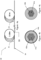
- Figures 4a, 4b and 4c show an embodiment of a PCF 30 which comprises two spliced fiber length sections, wherein at least one spliced fiber length section is or comprises a degradation resistant length section as described above.
- This type of fiber is also called a spliced cascaded optical fiber.
- Figure 4b is a cross sectional view of a first length section 31
- figure 4c is a cross sectional view of a second 32 length section spliced to the first length section.
- at least the first length section 31 of the PCF is a degradation resistant length section as described above.
- the PCF 30 is arranged for generating supercontinuum light upon feeding of light having a first wavelength ⁇ 1 e.g. from about 900 nm to about 1100 nm into the launching end 34 of the PCF 30,
- the optical fiber 30 comprises a first length section 31, a second length section 32 and a splicing 33 between the first and second length sections 32, 33.
- the optical fiber 30 may optionally include a not shown end cap to close the inclusions.
- the first length section 31 has a core 41a with a first core diameter W 1 and a cladding region 32a with a first pitch ⁇ 1 , a first inclusion diameter d 1 and a first relative size of inclusions ⁇ 1 /d 1 .
- the first length section comprises a main coating 44a which is hermetic for hydrogen and/or deuterium at a temperature below T h . Different types of preferred main coatings are described above. At least the first length section is loaded with hydrogen and/or deuterium.
- the second length section 32 has a core 41b with a second core diameter W 2 and a cladding region 42b with a second pitch ⁇ 2, a second inclusion diameter d 2 and a second relative size of inclusions ⁇ 2 /d 2 .
- At least one of the dimensions the first core diameter W 1 , the first pitch ⁇ 1 , the first inclusion diameter d 1 and the first relative size of inclusions ⁇ 1 /d 1 differs from the corresponding dimension the second core diameter W 2 , the second pitch ⁇ 2 , the second inclusion diameter d 2 and the second relative size of inclusions ⁇ 2 /d 2 of the second length section 32.
- the dimensions of the fiber are substantially constant and throughout the second length section 32 dimensions of the fiber are substantially constant.
- the respective lengths of the first and the second length section 31, 32 are in this embodiment respectively 1-10m and 10 m. However, it should be understood that these lengths are only given as example and the fiber length sections may in principle have any other lengths.
- FIG. 5 is a schematic representation of a supercontinuum light source.
- the supercontinuum light source 50 comprises a PCF 54 comprising a degradation resistant length section as described above and a pump source 52.
- the PCF has two ends: a launching end 55 and an output end 56.
- the launching end 55 of the PCF 54 has or is optically connected to a mode adaptor 58 for adapting the mode of the pump pulses from the pump source 52.
- the mode adaptor 58 is shown as if it is larger than the optical fiber 54; however, this is only for illustrative purpose and in practice the mode adaptor may have any suitable outer dimensions e.g. outer dimensions similar to those of the optical fiber 54.
- the output end 56 of the optical fiber 54 is shown as if it is a free end, the output end could have an end cap, or it could be spliced to further equipment.
- the pump light source 52 has an output 53 arranged to feed light into the PCF 54 via a delivery fiber 57 and via the mode adaptor 58 and a supercontinuum spectrum is generated in the PCF and output from the output end 56 of the PCF.
- the delivery fiber 57 may e.g. be omitted or replaced e.g. by an optical element such as a lens.
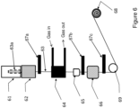
- the drawing tower shown in figure 6 is in the process of drawing a PCF 63 from a preform 63a.
- the preform is enclosed in a pressure control chamber 61 comprising one or more pressure chambers for controlling the pressure of gas inclusions in the PCF.
- a bottom part extends into a furnace 62, where the bottom part of the preform is heated to enable drawing the PCF 63.
- the velocity of the PCF and thereby the PCF diameter is controlled by the drawing wheel 69 pulling the PCF through the various stations of the drawing towers.
- the velocity of the PCF 63 is adjustable and by adjusting the temperature of the furnace 62 and the velocity of the PCF 63 the diameter of the fiber may be adjusted.
- the PCF is passed through a monitoring station 67a where the diameter of the PCFfrom the furnace 62 is monitored in-line.
- the PCF 63 is passed to the coating station for application of a main carbon coating.
- the PCF 63 is passed through the reactor chamber of the reactor 64 and as indicated with the arrows a reaction is introduced and withdrawn in a continuous flow to keep a substantially constant amount of fresh gas in the reactor.
- the reactor is positioned relatively close to where the PCF 63 leaves the furnace 62.
- an oven may be positioned prior to the reactor for preheat the PCF 63, however the latter alternative embodiment is not preferred due to the additional cost of the oven.
- the thickness of the carbon layer may be adjusted e.g. by adjusting the concentration of the reactive carbonaceous gas in the reaction gas or by changing the PCF velocity.
- the carbon coated PCF passes to an additional coating station for application of an additional coating, which in the shown embodiment is a polymer coating station 65. From the coating station the coated PCF is passed to a concentricity monitor 67b and further to a curing station 66 where the polymer coating is cured by light.
- the coated PCF is passed further to an additional monitor 67 c for monitoring the fiber diameter. From the drawing wheel 69 the coated PCF 63 passed to spooling onto a spool 68.
- the coated PCF 63 may advantageous be hydrogen or deuterium loaded on the spool by subjection the coated PCF on the spool 68 to the hydrogen and/or deuterium in a loading chamber.
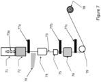
- the drawing tower shown in figure 7 is in the process of drawing a PCF 73 from a preform 73a.
- the preform is enclosed in a pressure control chamber 71 comprising one or more pressure chambers for controlling the pressure of gas inclusions in the PCF.
- a bottom part extends into a furnace 72, where the bottom part of the preform is heated and the fiber 73 is drawn to a desired thickness.
- the velocity of the fiber is controlled by the drawing wheel 79 pulling the PCF 73 through the various stations of the drawing towers. From the furnace 72 the fiber is passed through a monitoring station 77a where the diameter of the fiber is monitored in-line.
- the PCF 73 is passed to the coating station 74 for application of a main metal coating.
- the coating station 74 comprises a liquid metal melt at a relatively high temperature, but to ensure an even coating layer the fiber should have a temperature below the temperature of the melt.
- a blower or similar cooling means may be applied prior to the coating station 74 to blow cool air 70 to cool the PCF 73.
- Suitable melt temperatures are listed in table 1 Table 1 Metal Melt temperatures (°C) Aluminum 660 Aluminum Alloy 400 - 671 Gold, 24K Pure 1063 Cobber 1063 Alloys of Cobber and/or Gold 550-1063
- the PCF 73 is passed through the metal melt at a desired velocity equal to the fiber drawing velocity.
- the thickness of the metal coating may be adjusted e.g. by adjusting the amount of melt in the melt chamber of the coating station 74 or the fiber velocity.
- the metal coated PCF is passed further to an additional coating station 75 for application of an additional coating, which in the shown embodiment is a polymer coating station 75.
- an additional coating which in the shown embodiment is a polymer coating station 75.
- the coated PCF is passed to a concentricity monitor 77b and further to a curing station 76 where the polymer coating is cured by light.
- the coated PCF is passed further to an additional monitor 77 c for monitoring the fiber diameter. From the drawing wheel 79 the coated PCF is passed to spooling onto a spool 78.
Landscapes
- Chemical & Material Sciences (AREA)
- Physics & Mathematics (AREA)
- Life Sciences & Earth Sciences (AREA)
- Engineering & Computer Science (AREA)
- Materials Engineering (AREA)
- Geochemistry & Mineralogy (AREA)
- Organic Chemistry (AREA)
- Optics & Photonics (AREA)
- General Life Sciences & Earth Sciences (AREA)
- General Physics & Mathematics (AREA)
- Chemical Kinetics & Catalysis (AREA)
- General Chemical & Material Sciences (AREA)
- Nonlinear Science (AREA)
- Inorganic Chemistry (AREA)
- Manufacturing & Machinery (AREA)
- Crystallography & Structural Chemistry (AREA)
- Lasers (AREA)
- Optical Fibers, Optical Fiber Cores, And Optical Fiber Bundles (AREA)
- Surface Treatment Of Glass Fibres Or Filaments (AREA)
- Glass Compositions (AREA)
- Optical Modulation, Optical Deflection, Nonlinear Optics, Optical Demodulation, Optical Logic Elements (AREA)
- Optical Couplings Of Light Guides (AREA)
Description
- The invention relates to a photonic crystal fiber (PCF), a method of producing the PCF and a supercontinuum light source comprising such PCF, microstructured optical fiber and to a source of optical supercontinuum radiation.
- Photonic crystal fibers, in the following referred to as PCF or microstructured optical fibers (MSF), are fibers having a core surrounded by a cladding region having a plurality of inclusions (sometimes called cladding features or microstructures) arranged in a background material, typically in a regular array. The inclusion may be gas, liquid, or solid inclusion. In principle the inclusions could be void, but in practice the voids will normally comprise some gas molecules Fibers of this types are well known in the art and are for example described in
US2012195554 ,US8406594 ,US2011116283 andUS2012195554 - The microstructured fiber may for example be of silica glass. Other materials may be added to the silica glass in order to alter the refractive index thereof or to provide effects, such as amplification of light, sensitivity, etc.
- The center-to-center spacing between the cladding inclusions is defined as the pitch (Λ). The PCFs are usually at least partly characterized by the size of the core and the ratio of the size of the inclusions to their spacing or pitch (Λ). By tailoring the size and pitch of the cladding inclusions, the zero dispersion wavelength (ZDW) of the fiber may be tailored.
- Photonic crystal fibers are in general suitable for use in high power light sources. Guiding of relatively high powers in an optical fiber may have relevance for several commercial applications such as such as guiding of surgical and/or therapeutic light, optical sensing, and materials processing. Among such applications is transport of optical energy and utilizing of non-linear effects in the fiber which are commonly more pronounced with higher optical power inside the fiber. The optical power may be continuous wave (CW), pulsed or a mixture thereof. High optical power inside a fiber may be particularly pronounced with pulsed light where a high peak power may be obtainable even while having a relatively modest average power.
- One limitation of the average power/spectral density carried by an optical fiber is the damage threshold of the fiber. In particular where the PCF is applied for supercontinuum generation where high power light is fed to the PCF via a launching end (sometimes called an input end) of the PCF, it has been found that the PCF degrades over time in dependence on the peak power of the fed light. Further it has been found that a fiber section adjacent to or close to the launching end is more exposed to degradation than longer from the launching end.
-
US8145023 describes a method of alleviating the degradation caused by the high power light fed to the PCF by loading the core material and optionally the cladding material with hydrogen and/or deuterium. This loading was found to result in some increase in the lifetime of the fiber. InUS2011116283 the method was further improved by subjecting the PCF to an annealing and/or to a high power irradiation after the hydrogen and/or deuterium loading. -
US 6661957 B1 describes how a diffusion barrier attached to the cladding layer prevents significant diffusion of a Raman active gas out of the holes in a holey fiber or photonic band gap fiber. -
WO 2005/010583 A1 describes an optical fiber including a glass fiber having a glass core and a cladding which contains voids spaced apart from the core. The voids act as trapping sites for ingressing molecules from the surrounding environment, thereby reducing the effect of such molecules on the fiber's light transmission properties. - The invention is defined in the appended set of claims.
- An object of the present invention is to provide a PCF, equivalently MSF, suitable for supercontinuum generation, which PCF is very resistant against degradation.
- In an embodiment it is an object to provide a PCF suitable for supercontinuum generation, which PCF has a long life time even when used for supercontinuum generation.
- A further object is to provide a supercontinuum light source comprising a PCF with a high resistance against degradation as well as preferred applications of such supercontinuum light source.
- These and other objects have been solved by the invention or embodiments thereof as defined in the claims and as described herein below.
- It has been found that the invention or embodiments thereof have a number of additional advantages which will be clear to the skilled person from the following description.
- Photonic Crystal Fiber (PCF), equivalently microstructured optical fiber (MSF), of the invention has a longitudinal axis and comprises a core extending along the length of the longitudinal axis and a cladding region surrounding the core. At least the cladding region comprises a plurality of microstructures in the form of inclusions extending along the longitudinal axis of the PCF in at least a microstructured length section. The PCF has a degradation resistant length section which may be the entire length of the PCF or merely a length section thereof.
- The phrase "degradation resistant length section" is used to indicate that the fiber length section has a very high degradation resistance over time relative to other prior art fiber length sections.
- The PCF in at least the degradation resistant length section of said microstructured length section comprises hydrogen and/or deuterium and the PCF in at least the degradation resistant length section further comprises a main coating surrounding the cladding region, which main coating is hermetic for said hydrogen and/or deuterium at a temperature below Th, wherein Th is at least about 50 °C. Advantageously Th is at least about the maximal expected temperature of the PCF when in use. Thereby a minimum of the hydrogen and/or deuterium is diffused out of the fiber over time and/or during use. Preferably Th is as follows: 50 °C< Th < 250 °C. In an embodiment Th is up to about 150 °C.
- The term 'hermetic' is herein used to mean that any diffusion of the hydrogen atoms and/or deuterium atoms through the coating which is less than about 1 % per day measured e.g. using Raman spectroscopy and at the relevant temperature at atmosphere condition (i.e. the fiber is arranged at 1 bar in air) or by IR spectroscopy by measuring the absorption line of H2 (or D2) at around 1240 nm or around 1870 nm for H2 or around 1715 nm for D2. Preferably the hermetic coating allows a diffusion of less than 0.5 %, such as less than about 0.1 % per day, such as less than about 0.01% per day.
- The term "inclusions" means inclusions in a background material, wherein an inclusion has another refractive index than that of the background material surrounding it. The inclusions may e.g. be gas inclusions, such as of air, nitrogen or any other gas; solid inclusions, such of another glass type than the background material and/or a doped material (index changing materials such as F, Ge, P, B,), a vacuum inclusion or any combinations thereof. Advantageously at least some of the inclusions are gas - or vacuum inclusions. It has been found that gas inclusions may act as hydrogen/and or deuterium depots where the inclusions are closed on either side of the degradation resistant length section.
- The phrase "radial distance" means distance determined in radial direction from the longitudinal axis.
- The term "substantially" should herein be taken to mean that ordinary product variances and tolerances are comprised.
- It should be noted that the cladding region may have a homogeneous background material or it may have several regions with respective background materials which differ from each other. The background material is advantageously silica optionally doped In an embodiment the cladding region comprises an inner cladding region and an outer cladding region surrounding the inner cladding region wherein the background material of the inner cladding region differs from the background material of the outer cladding region e.g. as described in
US8600207 . - In an embodiment the cladding region comprises an inner cladding region and an outer cladding region surrounding the inner cladding region wherein the background material of the inner cladding region has the same refractive index as the background material of the outer cladding region. In this embodiment it is advantageous that the inner cladding region and the outer cladding region have the same background material. The difference between the inner and the outer cladding region is for example a difference of the size, type and/or number of inclusions. The cladding region confines the light to the core, and advantageously the inclusions are arranged to influence the average refractive index which results in the confining of the light. This means that the inclusions should be relatively close to the core, and preferably at least some of the inclusions should have a center-to-center distance to the core of up to about 50 µm, preferably up to about 40 µm, such as up to about 30 µm, such as up to about 15 µm.
- When describing the material of cladding region, inclusions and core, the amount of hydrogen and/or deuterium is not included as part of the material.
- In an embodiment the background material of the cladding region and the core material is substantially pure silica.
- In an embodiment the background material of the cladding region and the core material is silica doped with fluoride.
- It has been found that where the core material is doped with fluoride in at least the degradation resistant length section, an even higher resistance against photo induced degradations can be achieved.
- Advantageously the content of hydrogen and/or deuterium in the form of H2 or D2 in the core of at least the degradation resistant length section comprises at least about 0.001 ppm, such as at least about 0.01 ppm, such as from about 0.1 to about 10000 ppm. The amount of hydrogen and/or deuterium can e.g. be determined by determining the resulting absorption at respective hydrogen or deuterium absorption peaks as explained above.
- The degradation resistant length section may have any length. Advantageously the degradation resistant length section extends from an end of the PCF. In an embodiment the degradation resistant length section extends from the launching end of the PCF. The launching end is the end which is optically coupled or is adapted to be coupled to a pump laser for feeding light to the PCF. Thereby the degradation resistant length section can be positioned where the high power light is to be fed to the PCF. It has been observed that the major damage to the prior art PFC occurs close to a launching end of the PCF. By ensuring a sufficient load of hydrogen and/or deuterium at the launching end of the PCF, the PCF has a much increased resistance against damage due to loading stress, which further prolongs the lifetime for the whole PCF.
- In the context of the present application, the phrase "ring of inclusions" refers to the cladding inclusions typically having substantially equal distance to the core and being aligned in a circular or non-circular ring surrounding the core. Typically, a ring of inclusions is not fully circular, but rather shaped with a number of soft angles, such as in a hexagonal shape. Preferably all the inclusions of a ring of inclusions are of substantially the same size and preferably of same material.
- The plurality of inclusions in the cladding region are arranged in a pattern comprising at least two rings of inclusions surrounding the core.
- To obtain a PCF which is very good for supercontinuum generation - the center-to-center distance (also referred to as the pitch A) is advantageously at least about 1 µm, such as from about 1.5 µm to about 5 µm or larger. The inclusion diameter (d) is advantageously at least about: 0.5 µm, such as from about 1 µm to about 3 µm. The relative diameter/pitch d/Λ is preferably from about 0.4 to about 0.85.
- The inclusion diameter or the diameter of the inclusion is also referred to as the characteristic diameter of the inclusion. The phrase "characteristic diameter" is a measure of the size of an inclusion (also called a cladding feature). If the cladding feature is circular, the characteristic diameter is the diameter of the circle of the cladding feature. In case the cladding feature is not circular, the characteristic diameter is in an embodiment determined as the average of the maximum and the minimum extent of the cladding feature or in another embodiment the characteristic diameter is the diameter of a circle having an area corresponding to a calculated or measured area of the cladding feature in question.
- The inclusions may have equal or different diameters and the inclusion diameter of the respective inclusions may as mentioned be equal or differ along the length of the fiber.
- Embodiments of different and preferred combinations of inclusions and diameters thereof are disclosed in co-pending application
DK PA 2014 70146 PA 2014 70146 PA 2014 70146 - In an embodiment the inclusion diameter (d) of the respective inclusions is equal along the length of the fiber. In an embodiment the inclusion diameter (d) of the respective inclusions differs along at least a section of the length of the fiber - e.g. along a tapered section.
- The inclusions may - as indicated above - in principle comprise or consist of any kind of material, usually comprising material having a different refractive index than the background material in which the respective inclusion is embedded or comprised. Examples of suitable inclusion materials are disclosed above.
- In an embodiment the inclusions comprise gas inclusions, such as air holes - e.g. air holes with air at low or at surrounding (atmosphere pressure). Preferably the gas inclusions are closed on both sides of said degradation resistant length section.
- In an embodiment the degradation resistant length section is the whole length of the PCF optionally with exception of closed ends of the PCF.
- By closing the ends of the PCF any diffusion of hydrogen and/or deuterium out of the PCF is further reduced which has been found also to add to the degradation resistance and thereby the lifetime of the whole PCF.
- The ends of the PCF may for example be closed by collapsing the PCF in a short end section or by fusing a short solid silica length section to the respective ends.
- Advantageously the closed ends each have a relatively short length along the length of the PCF in order to reduce any risk of losing light. Advantageously the closed ends each have a length of the PCF of up to about 3 mm, such as up to about 2 mm, such as up to about 1 mm, such as up to about 0.5 mm, such as up to about 0.3 mm, such as up to about 0.2 mm.
- In an embodiment the plurality of inclusions in the cladding region of at least the degradation resistant length section comprise an inner cladding region comprising inner inclusions and an outer cladding region comprising outer inclusions. This embodiment has found to provide a very good PCF for supercontinuum generation. Advantageously the inner inclusions are larger than the outer inclusions. In an embodiment more preferably the inner inclusion has a diameter dinner which is at least about 15 % larger than a diameter douter of the outer inclusions, such as at least about 20%, such as at least about 25%, such as at least about 30 %. Thereby a PCF for supercontinuum generation with a high stability even in the blue light range is provided. Further due to the degradation resistant length section the PCF will have a long life time even where operating at very high power.
- In an embodiment dinner is preferably at least about 1.5 µm, such as from about 1.8 to about 4 µm, such as from about 2 to about 2.5 µm.
- In an embodiment douter is preferably at less than about 2.5 µm, such as from about 0.8 to about 2 µm, such as from about 1 to about 1.8 µ.
- Advantageously the background material of the inner cladding region and the background material of the outer cladding region are identical and optionally are also identical with the core material. Advantageously the background material of the inner cladding region and the background material of the outer cladding region and optionally the core material are substantially pure silica or optionally silica doped with fluorine.
- Advantageously, the outer cladding region comprises at least three rings of outer inclusions.
- The structure and the arrangement of the inclusions are in an embodiment as described in co-pending application
DK PA 2014 70146 DK PA 2014 70146 - The cladding region in at least the degradation resistant length section comprises an inner cladding region comprising the inclusions and an outer cladding region surrounding the inner cladding region wherein the radial distance between an outermost inclusion of the inner cladding region and the main coating is at least about 10 µm. Optionally the material between the inner cladding region and the main coating forms a reservoir for hydrogen and/or deuterium.
- By having a relatively large radial distance between the outermost inclusion of the inner cladding region and the main coating a large area may form a reservoir for hydrogen and/or deuterium which gradually can diffuse to the core as the hydrogen and/or deuterium is consumed in the core, thereby maintaining a relatively stable and sufficient concentration of hydrogen and/or deuterium in the core.
- In an embodiment the material between the inner cladding region and the main coating forms a reservoir for hydrogen and/or deuterium e.g. the reservoir for hydrogen is porous silica.
- In an embodiment the reservoir for hydrogen between the inner cladding region and the main coating comprises glass or plastic with a higher adsorption capacity for hydrogen and/or deuterium than the material of the inner cladding region background material.
- The skilled person will be able to find a suitable material by a few hydrogen and/or deuterium loading tests.
- The core may in principle have any size. The larger the core, the higher power can be fed to the PCF, however, if the core becomes too large it may become difficult to broaden the band width to a desired degree. In order to provide a broad and stable supercontinuum light it is advantageous that the core has a diameter of at least about 1 µm and preferably at least about 2 µm. Thereby it is ensured that the optical fiber is able to withstand the power necessary for supercontinuum generation and/or high power in general.
- In an embodiment the core in at least the degradation resistant length section has a core diameter of about 10 µm or less, such as about 8 µm or less, such as about 6 µm or less. In an embodiment the core diameter is in the range of from about 3 µm, such as about 3 µm to about 7 µm.
- In an embodiment the core is defined by the inclusions - i.e. the inclusions surrounding the core have a different refractive index which thereby forms the core.
- Advantageously the PCF is made from silica optionally doped as described above.
- In an embodiment the material of the core and/or of the cladding region is doped.
- In an embodiment an innermost inclusion in at least the degradation resistant length section has a center-to-center distance to the core of less than about 50 µm, preferably less than about 40 µm, such as less than about 30 µm, such as less than about 10 µm.
- The core is a solid core.
- The term "solid core" means that the core is of solid material substantially without gas comprising voids. In an embodiment the core is a microstructured core.
- Advantageously the core is a solid core optionally comprising solid microstructures.
- The core is in an embodiment substantially pure silica.
- As mentioned above a very beneficial property of a PCF is that by tailoring the size and pitch of the cladding inclusions, the zero dispersion wavelength (ZDW) of the fiber may be tailored.
- In an embodiment the PCF has anomalous dispersion for at least one wavelength between 1000 nm and 1100 nm. Preferably the PCF has an anomalous dispersion at about 1030 nm or 1064 nm.
- In an embodiment the core of the PCF is single mode at the pump wavelength.
- Advantageously the core of the PCF is spatially single mode at 1064 nm.
- Spatially single mode means that higher order modes have a loss which is at least 19.3 dB higher than the fundamental mode for a fiber with a length of 2 m. This can e.g. be measured using the
SA 2 method, see "Spatially and spectrally resolved imaging of modal content in large mode-area fibers", J. W. Nicholson et al, Optics Express, vol. 16, . - In an embodiment the core of the PCF is single mode at 1030 nm.
- In an embodiment the core of the PCF is multi-mode at the pump wavelength, such as at 1064 nm or at 1030.
- Advantageously at least the core of the PCF is essentially free of Germanium. It has been found that Germanium may result in certain structural defects within silica and therefore it is desired that the Germanium content is as low as possible. The hydrogen and/or deuterium has been found also to increase the resistance against Germanium induced structural defects and therefore where the PCF comprises Germanium the loading of hydrogen and/or deuterium may be increased.
- In an embodiment the entire PCF is essentially free of Germanium. In an embodiment the entire PCF is essentially undoped silica. In an embodiment at least a part of the PCF is doped with Fluorine e.g. at a level of above 1000 ppm.
- In the context of the present invention, the phrase "essentially free of Germanium" means that the concentration of germanium is less than about 10 ppm including zero.
- In the context of the present invention, the phrase "essentially undoped " means that the concentration of index-changing dopants, such as Ge, B, F, P, Al and/or active materials, such as the rare-earth elements Er or Yb, is at a level below 1000 ppm. In an embodiment the level of dopant is even lower such as about 1 ppm or less.
- In an embodiment at least the core of the PCF is essentially free of active material, such as rare earth ions.
- In an embodiment the entire PCF is free of active ions.
- In the context of the present invention, the phrase "essentially free of active material" means that the concentration of active materials, such as the rare-earth elements Er or Yb, is at a level below 1000 ppm. Preferable the level of active material is even lower such as about 1 ppm or less.
- The main coating may be of any material which provides a hermetic coating as defined above.
- Examples of suitable materials for the main coating are materials comprising nitride (such as carbon nitride, silicon nitride, boron nitride, silicon nitride and/or siliconoxy nitride), carbon, aluminum, metallic glass or a combination comprising one or more of the before mentioned.
- A particularly preferred material for the main coating is carbon.
- The thickness of the main coating is determined in dependence of the type of material. Generally it is desired to select material for the main coating which is hermetic at relatively low thickness thereby ensuring a high flexibility and bendability of the PCF without any substantial risk of formation of cracks.
- In an embodiment the main coating has a thickness of from about 5 nm to about 10 µm, such as from 10 nm to about 5 µm, such as from about 20 nm to about 1 µm.
- In an embodiment the main coating has a thickness of about 30 nm.
- For a metallic main coating the thickness is advantageously between 15 µm and 60 µm.
- In an embodiment the main coating is diffusion open for hydrogen and/or deuterium at a temperature above To' where To is larger than Th. Thereby the hydrogen and/or deuterium can be loaded into the PCF after the coating has been applied. This provides a preferred embodiment of producing the PCF since the main coating protects the fiber during handling both mechanically and against dust. Furthermore a more homogeneous and accurate content of hydrogen and/or deuterium can be loaded. It has been found that immediately after loading a PCF without the main coating will immediately start to lose the loaded hydrogen and/or deuterium and in practice an undesired large amount of hydrogen and/or deuterium may be lost prior to application of the main coating. Where the main coating is applied after the loading it is therefore desired that a larger amount of hydrogen and/or deuterium initially is loaded into the PCF.
- Preferably To is at least about 25°C, preferably To is in the interval from about 50 °C to about 300 °C, such as at least about 70 °C, such as at least about 100 °C. In an embodiment To is determined at 1 bar. In an embodiment To is determined at 100 bars.
- In general it is desired that To is larger than the temperature (or the expected temperature) of the PCF in use. On the other hand To should advantageously not increase the softening temperature of the material with the risk of deforming the material.
- The PCF may advantageously comprise one or more additional coatings above or below the main coating.
- Such additional coating may have the purpose of providing additional mechanical protection, of reducing any risk of cracks in the main coating and/or of providing an outermost appearance and/or touch.
- The additional coating is preferably a polymer coating advantageously comprising acrylate, polyimide, polyurethane, silicone or any combinations thereof.
- In an embodiment where the main coating is carbon an additional coating of metal, such as aluminum, gold, cobber, nickel, metallic glass or a combination or an alloy comprising at least one of the mentioned metals.
- In an embodiment the PCF comprises at least one tapered length section wherein the core in a first end of the tapered length section has a core diameter D1 and the core in a second end of the tapered length section has a core diameter D2, wherein D1 is larger than D2, preferably D2 is up to about 0.95 times D1, such as from about 0.1 to about 0.9 times D1. Advantageously the first end is the launching end.
- It has been found that by tapering the PCF the supercontinuum generation properties of the PCF may be increased e.g. as described in
PCT/DK2014/050205 PCT/DK2014/050205 - Preferably the first end of the tapered length section is at a launching end of the fiber or up to 5 cm along the length from the launching end of the fiber, preferably the first end of the tapered length section is adjacent to or comprised in the degradation resistant length section.
- Thereby the PCF is in particular protected against degradation where the peak power is very high.
- In an embodiment the PCF does not comprise any splicing.
- In an embodiment the PCF comprises two or more spliced fiber length sections, wherein at least one spliced fiber length section is or comprises the degradation resistant length section.
- In order to provide an optimal supercontinuum it has been found that a fiber comprising fiber length sections with different properties may be advantageous e.g. as described in
PCT/DK2014/050206 - In an embodiment the PCF comprises a first length section comprising or consisting of the degradation resistant length section and a second length section spliced to the first length section wherein the second length section has a lower content of hydrogen and/or deuterium than the degradation resistant length section.
- In an embodiment the PCF comprises
- a first length section with a first length L1, wherein the inclusions of the optical fiber at least at a first cross-section through the first length section perpendicularly to the longitudinal axis have a first pitch Λ1, a first inclusion diameter d1 and a first relative size d1/Λ1 of inclusions,
- a second length section with a second length L2, wherein the microstructure elements of the optical fiber at least at a second cross-section through the second length section perpendicularly to the longitudinal axis have a second pitch Λ2, a second inclusion diameter d2 and a second relative size d2/Λ2 of inclusions,
- at least one of the first length L1 and the second length L2 comprises or consists of the degradation resistant length section.
- One or more of the length sections of fiber may be tapered.
- In an embodiment the PCF of the invention is as described in
PCT/DK2014/050206 PCT/DK2014/050206 - In an embodiment PCF comprises a mode-adaptor extending along the length of the PCF in at least a mode-field adapting length section extending from a launching end of the PCF or up to about 5 cm from the launching end of the PCF. Preferably the mode-field adapting length section has a length of at least about 5 cm, such as at least about 10 cm, such as at least about 20 cm. Advantageously the mode-field adapting length section is partly or fully comprised in the degradation resistant length section.
- The invention also comprises a method of producing the PCF comprising
- producing a preform comprising a preform structure for the core and the cladding region of the PCF,
- drawing the preform to obtain the core and cladding region of the PCF,
- subjecting at least the degradation resistant length section of the PCF to hydrogen and/or deuterium loading, and
- applying the main coating to at least the degradation resistant length section of the PCF.
- Preferably the degradation resistant length section is the whole length of the PCF optionally with exception of the closed ends of the PCF. Advantageously the closed ends are as described above.
- In an embodiment the method comprises subjecting the PCF to hydrogen and/or deuterium loading prior to application of the main coating.
- Where the hydrogen and/or deuterium loading is performed prior to application of the main coating the hydrogen and/or deuterium loading comprises placing the PCF in a chamber containing hydrogen and/or deuterium at a pressure of at least about P1 and temperature of at least about T1 for a duration of at least t1.
- To provide a relatively fast loading of hydrogen and/or deuterium the temperature and optionally the pressure are advantageously raised.
- In an embodiment T1 is preferably at least 40 °C, such as from about 50 °C to about 250 °C, such as from about 100 °C to about 800 °C, such as up to about 500 °C, such as up to about 200 °C. In practice the material of the PCF sets the upper limit for the temperature T1.
- The loading time t1 is preferably at least about 1 hour, such as from about 2 hours to about 200 hours, such as from about 24 hours to about 96 hours.
- The loading pressure P1 is preferably from about 1 bar, such as from above 1 bar to about 250 bars, such as from about 50 bars to about 200 bars, such as from about 100 bars to about 200 bars.
- In this embodiment it is desired that the main coating is applied within a few hours of the loading because otherwise much of the loaded hydrogen and/or deuterium may diffuse out of the fiber. Preferably the main coating is applied to the PCF within about 5 hours, such as within about 2 hours of termination of the loading.
- In a preferred embodiment the method comprises subjecting the PCF to hydrogen and/or deuterium loading after application of the main coating.
- Thereby the loaded hydrogen and/or deuterium will almost not diffuse out of the PCF after loading and as described above the quality of the PCF may be increased. Further the amount of hydrogen and/or deuterium loaded may be lower which may result in a lower loading time.
- Preferably the method comprises
- producing a preform comprising a preform structure for the core and the cladding region of the PCF,
- drawing the preform to obtain the core and cladding region of the PCF,
- applying the main coating to the PCF,
- subjecting the PCF to hydrogen and/or deuterium at a temperature of at least about To, and
- cooling the PCF to Th or less.
- The cooling may be performed by passive cooling (just letting the PCF cool down e.g. at room temperature) or an active cooling e.g. blowing the PCF using cold air.
- In an embodiment where the main coating is applied prior to loading the hydrogen and/or deuterium, loading preferably comprises placing the PCF in a chamber containing hydrogen and/or deuterium at a pressure of at least about P2 and temperature of at least about T2> To for a duration of at least t2.
- In an embodiment T2 is preferably at least 50 °C, such as from about 75 °C to about 250 °C, such as from about 100 °C to about 200 °C or higher. In practice the material of the main coating or any additional coating(s) which may have been applied sets the upper limit for the temperature T2, which means that for some types of main coatings the temperature T2 may be up to about 500 °C or even up to about 800 °C.
- The loading time T2 is preferably at least about 1 hour, such as from about 2 hours to about 200 hours, such as from about 24 hours to about 96 hours.
- The loading pressure P2 is preferably from about 1 bar, such as from above 1 bar to about 250 bars, such as from about 50 bars to about 200 bars, such as from about 100 bars to about 200 bars.
- Where the PCF comprises gas inclusions, the method of producing the PCF preferably comprises closing the gas inclusions on either side of the degradation resistant length section. The method preferably comprises closing the gas inclusions in both ends de of the PCF.
- In an embodiment the method comprises closing the gas inclusions prior to subjecting the PCF to hydrogen and/or deuterium loading thereby reducing the risk of hydrogen and/or deuterium out-diffusion via the inclusions.
- In an embodiment the method comprises subjecting the PCF to hydrogen and/or deuterium loading prior to closing the gas inclusions at the ends of the fiber. In an embodiment the loading may comprise loading via the not closed gas inclusion followed by closing the gas inclusions at the ends of the fiber. In this embodiment the main coating may be applied prior to loading.
- The material of the main coating as well as the thickness thereof may be as described above.
- In an embodiment the main coating is applied to the PCF by chemical vapor deposition (CVD) or similar or modified deposition methods.
- In an embodiment the main coating is a carbon coating and the method comprises applying the main carbon coating by a chemical vapor deposition process. Advantageously the CVD process comprises pulling the fiber through a reactor chamber of a reactor and subjecting the fiber in the reactor chamber to a reactor gas at a temperature of at least about 700 °C. Preferably the temperature is in the interval of about 700 °C to about 1100 °C, such as about 700 °C to about 900 °C. A temperature above 900 °C may lead to formation of a carbon coating with a diamond like structure.
- The method of carbon coating the fiber may e.g. be as described in
US5000541 . - The reactor gas may advantageously comprise carbonaceous composition, preferably comprising alkyn (CnH2n-2), such as acetylene (C2H2) and/or alkene (CnH2n+2), such as ethane (C2H6), where n is 2 to 10, such as 2 to 4. Preferably the reactor gas is substantially free of oxygen.
- It has been found to be very effective to applying the main carbon coating immediately after drawing the fiber in a drawing tower. Thereby it is ensured that the surface of the fiber is not contaminated prior to application of the main coating and further it has been found that by applying the main carbon coating immediately after drawing the fiber without cooling down of the fiber to below a reaction temperature for the reactor gas prior to application of the carbon coating, the fiber need not being reheated prior to the carbon coating. In an alternative embodiment the fiber is reheated to the reaction temperature. The reaction temperature in the reaction chamber is advantageously at least about 700 °C, such as from about 800 °C to about 1100 °C.
- Advantageously the reactor is an integrated part of the drawing tower, preferably such that the fiber is pulled through the reactor chamber for application of the carbon coating prior to being coiled - i.e. in an in-line process.
- In an embodiment the method comprises applying an additional coating onto the carbon coating. The additional coating is preferably a polymer coating or a metal coating such as described above. The additional coating is preferably applied onto the carbon coating in the drawing tower prior to coiling the fiber.
- In an embodiment the main coating is a metal coating and the method comprises applying the main metal coating by pulling the fiber through a liquid metal melt, where the temperature of the fiber as it enters the melt is lower than the temperature of the metal melt.
- The temperature of the metal melt depends on the type of metal. In an embodiment the metal coating is applied to the fiber in the drawing tower after the fiber is drown and at least partially cooled down and preferably in an in-line process prior to coiling the fiber.
- In an embodiment the method comprises application of at least one additional coating e.g. outside the main coating.
- The invention also comprises a supercontinuum light source comprising the PCF as described above, and a pump source arranged to feed pump pulses to a launching end of the PCF.
- In an embodiment the PCF is arranged to generate a supercontinuum light with a broadened band width relative to the bandwidth of the pump pulses.
- Advantageously the PCF is arranged to generate a supercontinuum light with a band width relative to the bandwidth of the pump pulses which is broadened with at least about 100%, such as at least about 200%.
- In an embodiment the generated supercontinuum has a band width spanning at least an octave.
- The pump source can be any kind of pump source capable of providing pump pulses of sufficiently high energy e.g. a mode locked pump source such as a MOPA with or without pulse picker (gating means).
- The pump pulses preferable have a relative high peak power. In an embodiment pump pulses generated by the pulse source are high peak power pulses having a peak power at the launching end of the PCF of at least about 5 kW, such as at least about 10kW, such as at least about 15 kW, such as at least about 20 kW.
- In an embodiment the pump pulses generated by the pulse source have a pulse duration of up to about 200 ps, such as up to about 100 ps, such as up to about 50 ps, such as up to about 30 ps, such as up to about 10 ps, such as up to about 8 ps, such as up to about 5 ps, such as up to about 3 ps, such as up to about 1 ps.
- Advantageously the pump pulses generated by the pulse source have a pulse duration of at least about 200 fs, such as of at least about 1 ps, such as of at least about 5 ps.
- Preferably the pump pulses generated by the pulse source have a repetition rate of at least about 100 kHz, least about 10 kHz, such as of at least about 1 MHz, the repetition rate is preferably tunable e.g. using an EOM (electro-optic modulator), an AOM (acousto-optic modulator) or an AOTF (acousto-optic tunable filter) which simultaneously acts as a wavelength filter.
- In an embodiment the pump pulses generated by the pulse source have a wavelength of from about 900 nm to about 1100 nm, such as about 1030 or about 1064 nm.
- In an embodiment the supercontinuum light source has an average output power of at least about 1 W, such as at least about 5 W, such as at least about 10 W, such as at least about 20 W, such as at least about 50 W, such as at least about 100 W or even at least about 500 W. Generally it has been found that because of the degradation resistant length section of the PCF of the invention it has become possible to provide a high power supercontinuum light source with a desired high output power which simultaneously has a surprisingly long life time.
- In an embodiment the supercontinuum light source has an output comprising wavelengths less than about 600 nm, such as less than about 550 nm, such as less than about 450 nm, such as less than about 420 nm, such as less than about 410 nm, such as less than about 400 nm, such as less than about 380 nm, such as less than about 360 nm.
- In an embodiment the supercontinuum light source has an output comprising wavelengths more than about 1800 nm, such as more than about 2000 nm such as more than about 2200 nm.
- In an embodiment the supercontinuum light source further comprises a spectral filtering unit, arranged to filter the output of the supercontinuum source to a filtered SC output having a central wavelength of λ1 and an output bandwidth BW1, wherein at least one of the central wavelength of λ1 and the output bandwidth BW1 is tunable. The output bandwidth BW1 is advantageously (at least in one tuning) less than about 5 nm. The spectral filtering unit e.g. comprises an AOTF.
- The above and/or additional objects, features and advantages of the present invention will be further elucidated by the following illustrative and nonlimiting description of embodiments of the present invention, with reference to the appended drawings.
-
Figure 1 is a cross-sectional view of a PCF of an embodiment of the invention. -
Figure 2 is a cross-sectional view of a PCF of another embodiment of the invention. -
Figure 3 is a cross-sectional view of a PCF of yet another embodiment of the invention. -
Figures 4a, 4b and 4c show respectively a side view of a PCF according to an embodiment of the invention and cross-sections through a first and second length section thereof. -
Figure 5 is a schematic representation of an embodiment of a supercontinuum light source of radiation according to the invention. -
Figure 6 is a schematic drawing of a drawing tower where the main coating and an additional coating is applied in an in-line process and where the drawing tower comprises a coating station comprising a reactor for application of a carbon coating. -
Figure 7 is a schematic drawing of a drawing tower where the main coating and an additional coating is applied in an in-line process and where the drawing tower comprises a coating station application of a metal coating. - The figures are schematic and may be simplified for clarity. Throughout, the same reference numerals are used for identical or corresponding parts.
- Further scope of applicability of the present invention will become apparent from the description given hereinafter. However, it should be understood that the detailed description and specific examples, while indicating preferred embodiments of the invention, are given by way of illustration only, since various changes and modifications within the spirit and scope of the invention will become apparent to those skilled in the art from this detailed description.
- The PCF shown in
Figure 1 has a core 1 and acladding region inner cladding region 2 and anouter cladding region 3. The inner cladding region comprises a plurality of microstructures in the form of inclusions extending along the longitudinal axis of the PCF. As described above the inclusions can comprise any material, but are advantageously gas inclusions, such as air inclusions. Advantageously the inclusions are collapsed at one or more positions along the length of the fiber such as at each end of a degradation resistant length section which in one embodiment is substantially the whole length of the PCF as described above. - As it can be seen the cross sectional view of the PCF is a cross sectional view in the degradation resistant length section of the PCF, which as mentioned may comprise the whole length of the PCF or only a part of the length of the PCF.
- The PCF is loaded with not shown hydrogen and/or deuterium preferably in the form of hydrogen molecules and/or deuterium molecules (H2/D2). The hydrogen and/or deuterium will usually be in both the core 1 and the
cladding region main coating 4 which is hermetic for hydrogen and/or deuterium at a temperature below Th. Different types of preferred main coatings are described above. - The PCF comprises an
additional coating 5 for mechanical protection and optionally for providing the PCF with a desired appearance and/or texture. - In use when the PCF is subjected to high peak power of light, such as described above, the light may cause defects in the core material. This effects, which are believed to be caused by different chemical reactions are sometimes called photo induced degradation or photodarkning. The hydrogen and/or deuterium has been found to mitigate the degradation by binding to the material e.g. to terminate free radicals.
- As the hydrogen and/or deuterium in the core 1 is/are spent, fresh hydrogen and/or deuterium migrates to the core 1 from the
cladding region main coating 4 which is hermetic for hydrogen and/or deuterium when the PCF is in use or stored prior to use, the required amount of hydrogen and/or deuterium can be relatively low and/or the PCF is protected against excessive degradation for a long time, such as up to several years e.g. 3, 4 or even 5 years or longer. - The PCF is advantageously of silica e.g. doped as described above.
- The PCF shown in
figure 2 has acore 11 and acladding region 12 surrounding thecore 11. The PCF has a not shown length and a longitudinal axis which in the shown embodiment is coincident with the center axis of thecore 11. Thecladding region 12 comprises a plurality ofmicrostructures 12a in the form of inclusions in thecladding background material 12b. Theinclusions 12a extend along the longitudinal axis of the PCF. As described above the inclusions can comprise any material, but are advantageously gas inclusions, such as air inclusions. Advantageously the inclusions are collapsed at one or more positions along the length of the fiber such as at each end of a degradation resistant length section which in one embodiment is substantially the whole length of the PCF as described above. - The plurality of
inclusions 12a is arranged in the cladding region in a pattern comprising several rings of inclusions surrounding the core. The innermost ring of inclusions surrounding the core is marked with thedotted ring 12c. - As it can be seen the cross sectional view of the PCF is a cross sectional view in the degradation resistant length section of the PCF, which as mentioned may comprise the whole length of the PCF or only a part of the length of the PCF.
- The PCF comprises a
main coating 14 which is hermetic for hydrogen and/or deuterium at a temperature below Th. Different types of preferred main coatings are described above. - The PCF comprises an
additional material layer 16 which is sufficiently far from the core 11 to have any effect as a cladding (i.e. the refractive index of the material of thematerial layer 16 does not influence the light guiding of the core). - The
radial distance 17 between an outermost of theinclusions 12a of the cladding region and themain coating 14 is at least about 10 µm. - The
additional material layer 16 may be of the same or of a different material than thecladding background material 12b. Theadditional material layer 16 is advantageously selected to have a high capacity for hydrogen and/or deuterium to thereby act as a reservoir for hydrogen and/or deuterium. - The PCF is loaded with not shown hydrogen and/or deuterium as described above. The hydrogen and/or deuterium will usually be in both the
core 11 and thecladding region 12 as well as in theadditional material layer 16 - In use when the PCF is subjected to high peak power of light, such as described above, and as the hydrogen and/or deuterium in the
core 11 is/are spent fresh hydrogen and/or deuterium migrated to the core 11 from thecladding region 12 and thematerial layer 16. Due to themain coating 14 which is hermetic for hydrogen and/or deuterium when the PCF is in use or stored prior to use, the required amount of hydrogen and/or deuterium can be relatively low and/or the PCF is protected against excessive degradation for long time, such as up to several years e.g. 3, 4 or even 5 years or longer. - The PCF is advantageously of silica e.g. doped as described above.
- The PCF shown in
figure 3 has acore 21 and acladding region core 21. The PCF has a not shown length and a longitudinal axis which in the shown embodiment is coincident with the center axis of thecore 21. - The cladding region comprises an
inner cladding region 22 and anouter cladding region 23. Theinner cladding region 22 comprisesinner inclusions 22a in the inner cladding background material 22b. Theouter cladding region 23 comprisesouter inclusions 23a in the outer cladding background material 22b. - The
inner inclusions 22a comprise two rings of inner inclusions and theouter inclusions 23a comprise 5 rings of outer inclusions. - The
inclusions - The background material 22b of the
inner cladding region 22 and the background material 23b of theouter cladding region 23 and optionally the core material are advantageously of the same material such as of silica optionally doped with fluorine. - As it can be seen the cross sectional view of the PCF is a cross sectional view in the degradation resistant length section of the PCF, which as mentioned may comprise the whole length of the PCF or only a part of the length of the PCF.
- The PCF comprises a
main coating 24 which is hermetic for hydrogen and/or deuterium at a temperature below Th. Different types of preferred main coatings are described above. - The PCF comprises an additional material layer 26 which is sufficiently far from the core 21 to have any effect as a cladding.
- The additional material layer 26 is in this embodiment the same as the cladding background material 23b.
- The
radial distance 27 between an outermost of theinner inclusions 22a of the inner cladding region and themain coating 24 is at least about 10 µm. - The PCF is loaded with not shown hydrogen and/or deuterium as described above. The hydrogen and/or deuterium will usually be in both the
core 21 and thecladding region - In use when the PCF is subjected to high peak power of light, such as described above, and as the hydrogen and/or deuterium in the
core 21 is/are spent, fresh hydrogen and/or deuterium migrate to the core 21 from thecladding region -
Figures 4a, 4b and 4c show an embodiment of aPCF 30 which comprises two spliced fiber length sections, wherein at least one spliced fiber length section is or comprises a degradation resistant length section as described above. This type of fiber is also called a spliced cascaded optical fiber.Figure 4b is a cross sectional view of afirst length section 31 andfigure 4c is a cross sectional view of a second 32 length section spliced to the first length section. Preferably at least thefirst length section 31 of the PCF is a degradation resistant length section as described above. - The
PCF 30 is arranged for generating supercontinuum light upon feeding of light having a first wavelength λ1 e.g. from about 900 nm to about 1100 nm into the launchingend 34 of thePCF 30, - Along its length the
optical fiber 30 comprises afirst length section 31, asecond length section 32 and asplicing 33 between the first andsecond length sections optical fiber 30 may optionally include a not shown end cap to close the inclusions. - The
first length section 31 has acore 41a with a first core diameter W1 and a cladding region 32a with a first pitch Λ1, a first inclusion diameter d1 and a first relative size of inclusions Λ1/d1. The first length section comprises amain coating 44a which is hermetic for hydrogen and/or deuterium at a temperature below Th. Different types of preferred main coatings are described above. At least the first length section is loaded with hydrogen and/or deuterium. - The
second length section 32 has a core 41b with a second core diameter W2 and acladding region 42b with a second pitch Λ2, a second inclusion diameter d2 and a second relative size of inclusions Λ2/d2. - Advantageously at least one of the dimensions the first core diameter W1, the first pitch Λ1, the first inclusion diameter d1 and the first relative size of inclusions Λ1/d1 differs from the corresponding dimension the second core diameter W2, the second pitch Λ2, the second inclusion diameter d2 and the second relative size of inclusions Λ2/d2 of the
second length section 32. - Throughout the
first length section 31 the dimensions of the fiber are substantially constant and throughout thesecond length section 32 dimensions of the fiber are substantially constant. - The respective lengths of the first and the
second length section -
Figure 5 is a schematic representation of a supercontinuum light source. Thesupercontinuum light source 50 comprises aPCF 54 comprising a degradation resistant length section as described above and apump source 52. The PCF has two ends: a launchingend 55 and anoutput end 56. Infigure 5 , the launchingend 55 of thePCF 54 has or is optically connected to amode adaptor 58 for adapting the mode of the pump pulses from thepump source 52. Infigure 5 , themode adaptor 58 is shown as if it is larger than theoptical fiber 54; however, this is only for illustrative purpose and in practice the mode adaptor may have any suitable outer dimensions e.g. outer dimensions similar to those of theoptical fiber 54. Even though theoutput end 56 of theoptical fiber 54 is shown as if it is a free end, the output end could have an end cap, or it could be spliced to further equipment. - The
pump light source 52 has an output 53 arranged to feed light into thePCF 54 via adelivery fiber 57 and via themode adaptor 58 and a supercontinuum spectrum is generated in the PCF and output from theoutput end 56 of the PCF. Thedelivery fiber 57 may e.g. be omitted or replaced e.g. by an optical element such as a lens. - The drawing tower shown in
figure 6 is in the process of drawing aPCF 63 from apreform 63a. The preform is enclosed in apressure control chamber 61 comprising one or more pressure chambers for controlling the pressure of gas inclusions in the PCF. A bottom part extends into afurnace 62, where the bottom part of the preform is heated to enable drawing thePCF 63. The velocity of the PCF and thereby the PCF diameter is controlled by thedrawing wheel 69 pulling the PCF through the various stations of the drawing towers. The velocity of thePCF 63 is adjustable and by adjusting the temperature of thefurnace 62 and the velocity of thePCF 63 the diameter of the fiber may be adjusted. The PCF is passed through amonitoring station 67a where the diameter of the PCFfrom thefurnace 62 is monitored in-line. - From the
monitoring station 67a thePCF 63 is passed to the coating station for application of a main carbon coating. - The
PCF 63 is passed through the reactor chamber of thereactor 64 and as indicated with the arrows a reaction is introduced and withdrawn in a continuous flow to keep a substantially constant amount of fresh gas in the reactor. - To ensure that the
PCF 63 has a sufficiently high temperature when entering thereactor 64, it is desired that the reactor is positioned relatively close to where thePCF 63 leaves thefurnace 62. Alternatively an oven may be positioned prior to the reactor for preheat thePCF 63, however the latter alternative embodiment is not preferred due to the additional cost of the oven. - The thickness of the carbon layer may be adjusted e.g. by adjusting the concentration of the reactive carbonaceous gas in the reaction gas or by changing the PCF velocity.
- From the reactor the carbon coated PCF passes to an additional coating station for application of an additional coating, which in the shown embodiment is a
polymer coating station 65. From the coating station the coated PCF is passed to aconcentricity monitor 67b and further to a curingstation 66 where the polymer coating is cured by light. - From the curing
station 66 the coated PCF is passed further to anadditional monitor 67 c for monitoring the fiber diameter. From thedrawing wheel 69 thecoated PCF 63 passed to spooling onto aspool 68. - The
coated PCF 63 may advantageous be hydrogen or deuterium loaded on the spool by subjection the coated PCF on thespool 68 to the hydrogen and/or deuterium in a loading chamber. - The drawing tower shown in
figure 7 is in the process of drawing aPCF 73 from apreform 73a. The preform is enclosed in apressure control chamber 71 comprising one or more pressure chambers for controlling the pressure of gas inclusions in the PCF. A bottom part extends into afurnace 72, where the bottom part of the preform is heated and thefiber 73 is drawn to a desired thickness. The velocity of the fiber is controlled by thedrawing wheel 79 pulling thePCF 73 through the various stations of the drawing towers. From thefurnace 72 the fiber is passed through amonitoring station 77a where the diameter of the fiber is monitored in-line. - From the
monitoring station 77a thePCF 73 is passed to thecoating station 74 for application of a main metal coating. - The
coating station 74 comprises a liquid metal melt at a relatively high temperature, but to ensure an even coating layer the fiber should have a temperature below the temperature of the melt. A blower or similar cooling means may be applied prior to thecoating station 74 to blowcool air 70 to cool thePCF 73. - Suitable melt temperatures are listed in table 1
Table 1 Metal Melt temperatures (°C) Aluminum 660 Aluminum Alloy 400 - 671 Gold, 24K Pure 1063 Cobber 1063 Alloys of Cobber and/or Gold 550-1063 - The
PCF 73 is passed through the metal melt at a desired velocity equal to the fiber drawing velocity. The thickness of the metal coating may be adjusted e.g. by adjusting the amount of melt in the melt chamber of thecoating station 74 or the fiber velocity. - From the
coating station 74 the metal coated PCF is passed further to anadditional coating station 75 for application of an additional coating, which in the shown embodiment is apolymer coating station 75. From thecoating station 75 the coated PCF is passed to aconcentricity monitor 77b and further to a curingstation 76 where the polymer coating is cured by light. - From the curing
station 76 the coated PCF is passed further to anadditional monitor 77 c for monitoring the fiber diameter. From thedrawing wheel 79 the coated PCF is passed to spooling onto aspool 78.
Claims (16)
- A microstructured optical fiber (MSF) comprising a solid core extending along the length of a longitudinal axis of the MSF and a cladding region surrounding the core, wherein at least the cladding region comprises a plurality of microstructures in the form of inclusions extending along the longitudinal axis of the MSF in at least a degradation resistant microstructured length section, wherein the degradation resistant microstructured length section comprises hydrogen and/or deuterium, said MSF in at least said degradation resistant microstructured length section further comprises a coating surrounding the cladding region, wherein the coating is hermetic for said hydrogen and/or deuterium at a temperature below Th, wherein Th is at least 50 °C, preferably 50 °C< Th < 250 °C, wherein the cladding region in at least said degradation resistant microstructured length section comprises an inner cladding region comprising the plurality of inclusions and an outer cladding region surrounding the inner cladding region and wherein the radial distance between an outermost inclusion of the inner cladding region and the coating is at least 10 µm and wherein the inner cladding region comprises at least two rings of inclusions.
- The MSF of claim 1, wherein the plurality of inclusions in the cladding region of at least said degradation resistant microstructured length section comprises an inner cladding region comprising inner inclusions and an outer cladding region comprising outer inclusions wherein the inner inclusions are larger than the outer inclusions, preferably the inner inclusions comprise at least one ring of inclusions and the outer inclusions comprise at least one ring of outer inclusions, more preferably at least one of the inner inclusions has a diameter dinner which is at least 15 % larger than a diameter douter of the outer inclusions, such as at least 20%, such as at least 25%, such as at least 30 %.
- The MSF of any one of the preceding claims, wherein an innermost inclusion in at least said degradation resistant microstructured length section has a center-to-center distance to the core of less than 50 µm, preferably less than 40 µm, such as less than 30 µm, such as less than 10 µm.
- The MSF of any one of the preceding claims, wherein at least the core of the MSF is essentially free of Germanium, preferably at least the core is essentially undoped silica or fluorine doped silica, more preferably at least the core of the MSF is essentially free of active material, such as rare earth ions.
- The MSF of any one of the preceding claims, wherein the coating comprises nitride, carbon, aluminum, gold, copper, nickel, metallic glass or a combination or an alloy comprising one or more of the before mentioned.
- The MSF of any one of the preceding claims, wherein the MSF comprises at least one tapered length section wherein said core in a first end of the tapered length section has a core diameter D1 and said core in a second end of the tapered length section has a core diameter D2, wherein D1 is larger than D2, preferably D2 is up to 0.95 times D1, such as from 0.1 to 0.9 times D1.
- The MSF of any one of the preceding claims, wherein the MSF comprises at least two spliced fiber length sections, wherein at least one spliced fiber length section is or comprises said degradation resistant microstructured length section.
- The MSF of any one of the preceding claims, wherein the MSF comprises a mode-adaptor extending along the length of the MSF in at least a mode-field adapting length section extending from a launching end of the MSF or up to 5 cm from the launching end of the MSF, wherein said mode-field adapting length section has a length of at least 5 cm, such as at least 10 cm, such as at least 20 cm, advantageously said mode-field adapting length section is partly or fully comprised in said degradation resistant microstructured length section.
- A method of producing a MSF as claimed in any one of the preceding claims, wherein the method comprises• producing a preform comprising a preform structure for the core and the cladding region of the MSF,• drawing the preform to obtain the core and cladding region of the MSF,• subjecting at least the degradation resistant microstructured length section of the MSF to hydrogen and/or deuterium loading, and• applying the coating to at least said degradation resistant microstructured length section of the MSF,preferably said degradation resistant microstructured length section is the whole length of the MSF optionally with exception of closed ends of the MSF, said closed ends each have a length along the length of the MSF of up to 3 mm, such as up to 2 mm, such as up to 1 mm, such as up to 0.5 mm, such as up to 0.3 mm, such as up to 0.2 mm.
- The method of claim 9, wherein the method comprises subjecting the MSF to hydrogen and/or deuterium loading prior to application of the coating.
- The method of claim 9, wherein the method comprises subjecting the MSF to hydrogen and/or deuterium loading after application of the coating, preferably the method comprises• producing a preform comprising a preform structure for the core and the cladding region of the MSF,• drawing the preform to obtain the core and cladding region of the MSF,• applying the coating to the MSF,• subjecting the MSF to hydrogen and/or deuterium at a temperature of at least about To, and• cooling the MSF to Th or less.
- A supercontinuum light source comprising the MSF of any one of claims 1-8, and a pump source arranged to feed pump pulses with a peak power of at least 5kW to a launching end of said MSF, preferably said MSF is arranged to generate a supercontinuum light with a broadened band width relative to the bandwidth of said pump pulses.
- The supercontinuum light source of claim 12, wherein the pump pulses generated by said pulse source have a pulse duration of up to 200 ps, such as up to 100 ps, such as up to 50 ps, such as up to 30 ps, such as up to 10 ps, such as up to 8 ps, such as up to 5 ps, such as up to 3 ps, such as up to 1 ps.
- The supercontinuum light source of any one of claims 12-13, wherein the pump pulses generated by said pulse source have a repetition rate of at least 10 kHz, such as of at least 100 kHz, such as at least 1 MHz, said repetition rate is preferably tunable.
- The supercontinuum light source of any one of claims 12-14, wherein the supercontinuum light source has an average output power of at least 1 W, such as at least 5 W, such as at least 50 W, such as at least 500 W, preferably the supercontinuum light source has an output comprising wavelengths less than 600 nm, such as less than 450 nm, such as less than 400 nm.
- The supercontinuum light source of any one of claims 12-15, wherein the supercontinuum light source further comprises a spectral filtering unit, arranged to filter the output of said supercontinuum source to a filtered supercontinuum output having a central wavelength of λ1 and an output bandwidth BW1, wherein at least one of the central wavelength of λ1 and the output bandwidth BW1 is tunable, said output bandwidth BW1 is advantageously less than 5 nm.
Applications Claiming Priority (2)
| Application Number | Priority Date | Filing Date | Title |
|---|---|---|---|
| DKPA201470800 | 2014-12-18 | ||
| PCT/DK2015/050395 WO2016095923A1 (en) | 2014-12-18 | 2015-12-15 | A photonic crystal fiber, a method of production thereof and a supercontinuum light source |
Publications (3)
| Publication Number | Publication Date |
|---|---|
| EP3234665A1 EP3234665A1 (en) | 2017-10-25 |
| EP3234665A4 EP3234665A4 (en) | 2018-08-08 |
| EP3234665B1 true EP3234665B1 (en) | 2024-08-21 |
Family
ID=56125969
Family Applications (1)
| Application Number | Title | Priority Date | Filing Date |
|---|---|---|---|
| EP15869379.6A Active EP3234665B1 (en) | 2014-12-18 | 2015-12-15 | A photonic crystal fiber, a method of production thereof and a supercontinuum light source |
Country Status (9)
| Country | Link |
|---|---|
| US (7) | US10228510B2 (en) |
| EP (1) | EP3234665B1 (en) |
| JP (4) | JP7244205B2 (en) |
| KR (2) | KR102663955B1 (en) |
| CN (3) | CN107209323A (en) |
| HK (1) | HK1243186A1 (en) |
| IL (2) | IL291919B2 (en) |
| SG (1) | SG11201704974TA (en) |
| WO (1) | WO2016095923A1 (en) |
Families Citing this family (19)
| Publication number | Priority date | Publication date | Assignee | Title |
|---|---|---|---|---|
| IL247885B2 (en) | 2014-03-25 | 2024-04-01 | Nkt Photonics As | A fiber with a tiny structure and a super wideband light source |
| HK1243186A1 (en) | 2014-12-18 | 2018-07-06 | Nkt光子学有限公司 | A photonic crystal fiber, a method of production thereof and a supercontinuum light source |
| CN106785839A (en) * | 2016-12-16 | 2017-05-31 | 中国电子科技集团公司电子科学研究院 | A kind of optical fiber laser with super continuous spectrum |
| GB201711849D0 (en) | 2017-07-24 | 2017-09-06 | Nkt Photonics As | Reducing light-induced loss in optical fibre |
| US10989868B1 (en) * | 2017-09-14 | 2021-04-27 | Apple Inc. | Fabric items with thermally imprinted light-emitting regions |
| US11401196B2 (en) | 2018-06-01 | 2022-08-02 | Corning Incorporated | Microstructured glass articles with at least 100 core elements and methods for forming the same |
| CN109861065A (en) * | 2018-12-12 | 2019-06-07 | 江苏师范大学 | Visible light-enhanced supercontinuum light source based on suspended core fiber |
| CN113631999B (en) | 2019-03-25 | 2023-05-16 | Asml荷兰有限公司 | Frequency widening device and method |
| CA3053149A1 (en) | 2019-05-01 | 2020-11-01 | National Research Council Of Canada | Boron nitride nanotube coated optical waveguide and uses thereof |
| CN110445002B (en) * | 2019-07-23 | 2021-08-06 | 南京邮电大学 | A device and method for generating supercontinuum from low-pump few-mode photonic crystal fiber |
| CN112094052B (en) * | 2019-09-16 | 2022-01-28 | 中国科学院上海光学精密机械研究所 | Radiation-resistant quartz optical fiber preform core rod and preparation method thereof |
| US10983269B1 (en) * | 2019-10-02 | 2021-04-20 | Verrillon, Inc. | Optical fibers with two metal coatings surrounding the cladding |
| DK3832363T3 (en) | 2019-12-03 | 2025-02-10 | Asml Netherlands Bv | A device and method for connecting a fiber preform to a pressure supply system |
| EP4090636A1 (en) | 2020-01-17 | 2022-11-23 | Corning Incorporated | Reduced coating diameter chlorine-doped silica optical fibers with low loss and microbend sensitivity |
| EP3904954B1 (en) * | 2020-04-27 | 2023-08-23 | NKT Photonics A/S | Optical source and supercontinuum light generation apparatus |
| CN111443422B (en) * | 2020-06-03 | 2021-03-05 | 中国科学院物理研究所 | Topological photonic crystal fiber, fiber preform, and manufacturing method thereof |
| WO2022161703A1 (en) * | 2021-01-27 | 2022-08-04 | Asml Netherlands B.V. | Hollow-core photonic crystal fiber |
| JP7607269B2 (en) * | 2022-10-18 | 2024-12-27 | 学校法人近畿大学 | Zero-dispersion and dispersion-flattened photonic crystal fiber |
| CN116413849B (en) * | 2023-03-20 | 2023-09-19 | 浙江大学 | Single polarization single mode PCF, parameter determination method and performance analysis method |
Family Cites Families (98)
| Publication number | Priority date | Publication date | Assignee | Title |
|---|---|---|---|---|
| JPS6090852A (en) | 1983-10-22 | 1985-05-22 | Furukawa Electric Co Ltd:The | Treatment of glass for optical fiber |
| US4606608A (en) * | 1985-02-04 | 1986-08-19 | Hughes Aircraft Company | Process and apparatus for preparing glass fibers coated with amorphous metallic alloy, and fibers coated thereby |
| US5000541A (en) | 1987-09-18 | 1991-03-19 | At&T Bell Laboratories | Hermetically sealed optical fibers |
| JP2644018B2 (en) * | 1988-12-13 | 1997-08-25 | 株式会社フジクラ | Optical fiber manufacturing method |
| JPH0459630A (en) | 1990-06-27 | 1992-02-26 | Sumitomo Electric Ind Ltd | Optical fiber manufacturing method |
| US5152817A (en) * | 1991-01-15 | 1992-10-06 | Corning Incorporated | Reactor for coating optical fibers |
| US5256177A (en) | 1991-01-15 | 1993-10-26 | Corning Incorporated | Method for coating optical fibers |
| US5235659A (en) | 1992-05-05 | 1993-08-10 | At&T Bell Laboratories | Method of making an article comprising an optical waveguide |
| US5267343A (en) | 1992-09-03 | 1993-11-30 | The United States Of America As Represented By The United States Department Of Energy | Enhanced radiation resistant fiber optics |
| US5621843A (en) | 1994-06-09 | 1997-04-15 | Ceramoptec Industries, Inc. | Silica lightguide for UV applications |
| JP3719776B2 (en) * | 1996-05-23 | 2005-11-24 | ヘレウス・クアルツグラース・ゲゼルシャフト・ミット・ベシュレンクテル・ハフツング | Optical fiber for ultraviolet transmission, manufacturing method thereof, and transmission line using the same |
| EP0780707A1 (en) | 1995-12-21 | 1997-06-25 | Heraeus Quarzglas GmbH | Element for UV high energy radiation transmission and method of fabrication of such an element and its utilisation |
| EP0810453B1 (en) * | 1996-05-31 | 2001-10-10 | Lucent Technologies Inc. | Article comprising a micro-structured optical fiber, and method of making such fiber |
| US5802236A (en) | 1997-02-14 | 1998-09-01 | Lucent Technologies Inc. | Article comprising a micro-structured optical fiber, and method of making such fiber |
| US6763686B2 (en) | 1996-10-23 | 2004-07-20 | 3M Innovative Properties Company | Method for selective photosensitization of optical fiber |
| US6311524B1 (en) | 2000-07-14 | 2001-11-06 | 3M Innovative Properties Company | Accelerated method for increasing the photosensitivity of a glassy material |
| JP2000203856A (en) | 1999-01-12 | 2000-07-25 | Sumitomo Electric Ind Ltd | Quartz glass article and method for producing the same |
| JP3456449B2 (en) | 1997-05-16 | 2003-10-14 | 住友電気工業株式会社 | Quartz glass article and method for producing the same |
| JP2980094B2 (en) | 1997-05-16 | 1999-11-22 | 住友電気工業株式会社 | Quartz glass article and method for producing the same |
| US5901264A (en) | 1997-06-12 | 1999-05-04 | Fiberguide Industries | Solar resistant optical fiber and method |
| JPH11189438A (en) * | 1997-12-26 | 1999-07-13 | Furukawa Electric Co Ltd:The | Manufacturing method of radiation resistant optical fiber |
| US6130981A (en) | 1998-03-20 | 2000-10-10 | Polymicro Technologies, Llc | Gamma radiation sterilized fiber optic UV delivery systems |
| US6404961B1 (en) * | 1998-07-23 | 2002-06-11 | Weatherford/Lamb, Inc. | Optical fiber cable having fiber in metal tube core with outer protective layer |
| JP3517129B2 (en) | 1998-10-30 | 2004-04-05 | 日本電信電話株式会社 | Short pulse light source |
| US6243522B1 (en) | 1998-12-21 | 2001-06-05 | Corning Incorporated | Photonic crystal fiber |
| JP2000258810A (en) | 1999-03-08 | 2000-09-22 | Shin Etsu Chem Co Ltd | Secondary optical non-linear glass material and method of manufacturing the same |
| AUPP961299A0 (en) | 1999-04-07 | 1999-05-06 | Metal Storm Limited | Projectile launching apparatus |
| US6334017B1 (en) | 1999-10-26 | 2001-12-25 | Corning Inc | Ring photonic crystal fibers |
| US6496627B1 (en) | 2000-07-14 | 2002-12-17 | Tyco Telecommunications (Us) Inc. | Device and method for improved long term signal attenuation performance of fiber optic cable and apparatus interfaces |
| JP3393120B2 (en) | 2001-01-16 | 2003-04-07 | 科学技術振興事業団 | Optical fiber for ultraviolet light transmission and method of manufacturing the same |
| US6944380B1 (en) | 2001-01-16 | 2005-09-13 | Japan Science And Technology Agency | Optical fiber for transmitting ultraviolet ray, optical fiber probe, and method of manufacturing the optical fiber probe |
| US6496634B1 (en) * | 2001-07-17 | 2002-12-17 | Marc David Levenson | Holey fibers filled with raman active fluid |
| US6661957B1 (en) * | 2001-07-17 | 2003-12-09 | Marc David Levenson | Diffusion barriers for holey fibers |
| US6856713B2 (en) | 2001-08-20 | 2005-02-15 | Polymicro Technologies, Llc | Optical component and method of making the same |
| JP3892724B2 (en) | 2001-12-25 | 2007-03-14 | 三菱電線工業株式会社 | Manufacturing method of optical fiber for ultraviolet transmission |
| AU2003226893A1 (en) | 2002-03-18 | 2003-09-29 | Crystal Fibre A/S | Preform, method of its production, and use thereof in production of microstructured optical fibres |
| JP3910486B2 (en) | 2002-05-17 | 2007-04-25 | 株式会社フジクラ | Optical fiber and optical transmission line |
| US6847771B2 (en) | 2002-06-12 | 2005-01-25 | Corning Incorporated | Microstructured optical fibers and preforms and methods for fabricating microstructured optical fibers |
| US6775447B2 (en) | 2002-09-20 | 2004-08-10 | Fitel Usa Corp. | All fiber low noise supercontinuum source |
| WO2004049025A1 (en) | 2002-11-23 | 2004-06-10 | Crystal Fibre A/S | Splicing and connectorization of photonic crystal fibres |
| JP2004177817A (en) | 2002-11-28 | 2004-06-24 | Sumitomo Electric Ind Ltd | Optical fiber and optical module |
| JP4116479B2 (en) | 2003-03-17 | 2008-07-09 | 三菱電線工業株式会社 | Tapered photonic crystal fiber, manufacturing method thereof, and connection method of photonic crystal fiber |
| US20040223694A1 (en) | 2003-04-04 | 2004-11-11 | Dower William V. | Method and apparatus for the photosensitization of optical fiber |
| JP2004345919A (en) | 2003-05-23 | 2004-12-09 | Fujikura Ltd | Optical fiber manufacturing method |
| JP2004361526A (en) * | 2003-06-03 | 2004-12-24 | Mitsubishi Cable Ind Ltd | Optical fiber and manufacturing method for fiber grating using the same |
| WO2005010583A1 (en) * | 2003-07-17 | 2005-02-03 | Verrillon, Incorporated | Optical fibers with improved resistance to ingressing molecules |
| JP2005037570A (en) * | 2003-07-18 | 2005-02-10 | Sumiden High Precision Co Ltd | Optical fiber splicing adapter and its manufacturing method |
| JP2005112690A (en) * | 2003-10-10 | 2005-04-28 | Furukawa Electric Co Ltd:The | Manufacturing method of optical waveguide |
| WO2005054144A1 (en) | 2003-12-03 | 2005-06-16 | Lg Cable Ltd. | Fabrication method of optical fiber preform and optical fiber containing few hydroxyl groups |
| JP4579710B2 (en) | 2004-02-20 | 2010-11-10 | フルカワ エレクトリック ノース アメリカ インコーポレーテッド | Modification, enhancement and adjustment of light generation in highly nonlinear fibers by post-processing |
| JP2006030655A (en) | 2004-07-16 | 2006-02-02 | Furukawa Electric Co Ltd:The | Optical fiber and its evaluation method and manufacturing method |
| JP3917613B2 (en) * | 2004-08-11 | 2007-05-23 | 日本電信電話株式会社 | Photonic crystal optical fiber |
| CN101010607A (en) | 2004-08-25 | 2007-08-01 | 科赫拉斯公司 | A method of inducing refractive index structures in a micro-structured fiber, a micro-structured fiber and an article |
| JP5255838B2 (en) * | 2004-08-25 | 2013-08-07 | ケーエルエー−テンカー コーポレイション | Fiber amplifier based light source for semiconductor inspection |
| CN1259581C (en) * | 2004-11-18 | 2006-06-14 | 上海大学 | Magneto-optic effect photon crystal fiber and manufacturing method thereof |
| JP2006221031A (en) | 2005-02-14 | 2006-08-24 | Tomoegawa Paper Co Ltd | Optical connection structure |
| US7266276B2 (en) | 2005-02-18 | 2007-09-04 | Verrilon, Inc. | Optical fibers with improved resistance to ingressing molecules |
| CA2541735C (en) | 2005-04-06 | 2011-03-15 | Weatherford/Lamb, Inc. | Conditioning optical fibers for improved ionizing radiation response |
| JP2007025087A (en) * | 2005-07-14 | 2007-02-01 | Nippon Telegr & Teleph Corp <Ntt> | Photonic crystal fiber and optical transmission system using the same |
| JP2007071950A (en) * | 2005-09-05 | 2007-03-22 | Fujikura Ltd | Double clad holey fiber, fiber amplifier and fiber laser |
| EP1925975A4 (en) | 2006-01-20 | 2010-04-28 | Sumitomo Electric Industries | DEVICE WITH LIGHT SOURCE |
| US8718411B2 (en) | 2006-07-07 | 2014-05-06 | The University Of Sydney | Tunable optical supercontinuum enhancement |
| EP2056135B1 (en) | 2006-11-21 | 2015-06-10 | The Furukawa Electric Co., Ltd. | Optical fiber and light guide |
| EP2111564B1 (en) | 2007-01-12 | 2018-04-25 | NKT Photonics A/S | Lifetime extending and performance improvements of micro-structured fibres via high temperature loading |
| CA2677014C (en) * | 2007-02-15 | 2013-11-12 | Institut National D'optique | Archimedean-lattice microstructured optical fiber |
| CA2579828C (en) * | 2007-02-23 | 2014-06-03 | Her Majesty In Right Of Canada As Represented By The Minister Of Industry, Through The Communications Research Centre Canada | Method of changing the refractive index in a region of a core of a photonic crystal fiber using a laser |
| US7493009B2 (en) | 2007-05-25 | 2009-02-17 | Baker Hughes Incorporated | Optical fiber with tin doped core-cladding interface |
| JP5366222B2 (en) | 2007-06-11 | 2013-12-11 | コリア・インスティテュート・オブ・オーシャン・サイエンス・アンド・テクノロジー | Algicidal active proteolytic enzyme, gene encoding the same, and algicidal preparation containing the same |
| CN103246014B (en) * | 2007-09-26 | 2015-12-23 | Imra美国公司 | Glass large-core optical fibers |
| JP2009175271A (en) * | 2008-01-22 | 2009-08-06 | Ntt Advanced Technology Corp | Optical fiber end shape and optical fiber end processing method |
| JP2009188094A (en) | 2008-02-05 | 2009-08-20 | Fujikura Ltd | Optical fiber for optical amplification and optical fiber laser |
| WO2009107260A1 (en) * | 2008-02-29 | 2009-09-03 | 古河電気工業株式会社 | Optical fiber |
| EP2307915A2 (en) * | 2008-07-11 | 2011-04-13 | NKT Photonics A/S | Lifetime extending and performance improvements of optical fibers via loading |
| DK2321678T3 (en) | 2008-08-18 | 2019-03-11 | Nkt Photonics As | Optical fiber with resonant structure of casing connected to a light receiver |
| JP2010135501A (en) | 2008-12-03 | 2010-06-17 | Elpida Memory Inc | Method of manufacturing semiconductor device |
| FR2939522B1 (en) | 2008-12-08 | 2011-02-11 | Draka Comteq France | OPTICAL FIBER AMPLIFIER RESISTANT TO IONIZING RADIATION |
| EP2369380A4 (en) | 2008-12-24 | 2014-04-16 | Furukawa Electric Co Ltd | OPTICAL FIBER AT MULTIPLE |
| JP2010169965A (en) | 2009-01-23 | 2010-08-05 | Asahi Glass Co Ltd | Photonic crystal fiber and manufacturing method of the same |
| US11402572B2 (en) * | 2009-03-04 | 2022-08-02 | Nkt Photonics A/S | Microstructured hollow core optical fiber using low chlorine concentration |
| JP5363172B2 (en) * | 2009-04-08 | 2013-12-11 | 三菱電線工業株式会社 | Optical fiber |
| US8218928B2 (en) * | 2009-04-23 | 2012-07-10 | Ofs Fitel, Llc | Spatial filtering of higher order modes in multimode fibers |
| WO2011018094A1 (en) | 2009-08-14 | 2011-02-17 | Nkt Photonics A/S | Improvements relating to splicing and connectorization of photonic crystal fibers |
| JP5329347B2 (en) * | 2009-08-27 | 2013-10-30 | 湖北工業株式会社 | Optical fiber for ultraviolet transmission and method for manufacturing the same |
| DK2612184T3 (en) | 2010-08-30 | 2022-12-12 | Nkt Photonics As | TAPERED, OPTICAL FIBER FOR GENERATION OF A SUPER CONTINUUM |
| US10564412B2 (en) | 2010-12-10 | 2020-02-18 | Nkt Photonics A/S | Tunable filter including an angular dispersive element for a broad band source |
| CN102147496A (en) * | 2011-03-23 | 2011-08-10 | 华中科技大学 | Ionization-irradiation-resistant active optical fiber for space |
| JP2012233977A (en) * | 2011-04-28 | 2012-11-29 | Mitsubishi Cable Ind Ltd | Metal coated optical fiber and method for manufacturing the same |
| JP5888966B2 (en) | 2011-12-16 | 2016-03-22 | 古河電気工業株式会社 | Photonic band gap fiber manufacturing method |
| FR2987905B1 (en) * | 2012-03-08 | 2015-03-20 | Commissariat Energie Atomique | DEVICE FOR CONVERTING THE TRANSVERSE SPATIAL PROFILE OF INTENSITY OF A LUMINOUS BEAM, PREFERABLY USING A MICROSTRUCTURED OPTICAL FIBER |
| CN103022867A (en) * | 2012-12-18 | 2013-04-03 | 中国人民解放军国防科学技术大学 | High-power high-efficiency supercontinuum source |
| GB2511043B (en) * | 2013-02-20 | 2016-03-23 | Fianium Ltd | A supercontinuum source |
| US9353001B2 (en) | 2013-03-14 | 2016-05-31 | Ofs Fitel, Llc | Fiber bragg gratings in carbon-coated optical fibers and techniques for making same |
| JP6104835B2 (en) * | 2013-03-14 | 2017-03-29 | オーエフエス ファイテル,エルエルシー | Fiber Bragg gratings in carbon-coated optical fibers and techniques for their manufacture. |
| FR3008194B1 (en) * | 2013-07-05 | 2015-08-07 | Ixfiber | METHOD FOR MANUFACTURING A RADIATION-RESISTANT OPTICAL FIBER, RADIATION-RESISTANT OPTICAL FIBER, AND DEVICE COMPRISING SUCH A FIBER |
| DK3019899T3 (en) | 2013-07-10 | 2021-10-11 | Nkt Photonics As | SUPERCONTINUUM FORMATION IN MICROSTRUCTURED OPTICAL FIBERS BY TAPPING AND ADJUSTING NON-DISPERGER WAVE LENGTH (S) |
| WO2015003715A1 (en) | 2013-07-10 | 2015-01-15 | Nkt Photonics A/S | Microstructured optical fiber, supercontinuum light source comprising microstructured optical fiber and use of such light source |
| IL247885B2 (en) | 2014-03-25 | 2024-04-01 | Nkt Photonics As | A fiber with a tiny structure and a super wideband light source |
| HK1243186A1 (en) | 2014-12-18 | 2018-07-06 | Nkt光子学有限公司 | A photonic crystal fiber, a method of production thereof and a supercontinuum light source |
-
2015
- 2015-12-15 HK HK18102705.2A patent/HK1243186A1/en unknown
- 2015-12-15 WO PCT/DK2015/050395 patent/WO2016095923A1/en not_active Ceased
- 2015-12-15 KR KR1020177020107A patent/KR102663955B1/en active Active
- 2015-12-15 CN CN201580075601.1A patent/CN107209323A/en active Pending
- 2015-12-15 KR KR1020247014605A patent/KR20240064049A/en active Pending
- 2015-12-15 IL IL291919A patent/IL291919B2/en unknown
- 2015-12-15 CN CN202210516366.9A patent/CN114879300B/en active Active
- 2015-12-15 SG SG11201704974TA patent/SG11201704974TA/en unknown
- 2015-12-15 JP JP2017532646A patent/JP7244205B2/en active Active
- 2015-12-15 CN CN202210516426.7A patent/CN114879301B/en active Active
- 2015-12-15 EP EP15869379.6A patent/EP3234665B1/en active Active
- 2015-12-15 US US15/537,005 patent/US10228510B2/en active Active
-
2017
- 2017-06-15 IL IL252963A patent/IL252963B/en unknown
-
2019
- 2019-01-23 US US16/254,884 patent/US10557987B2/en active Active
-
2020
- 2020-02-10 US US16/786,027 patent/US10928584B2/en active Active
- 2020-10-30 JP JP2020182910A patent/JP2021039360A/en active Pending
-
2021
- 2021-02-22 US US17/181,963 patent/US11409033B2/en active Active
-
2022
- 2022-07-01 US US17/856,415 patent/US11719881B2/en active Active
- 2022-12-14 JP JP2022199398A patent/JP2023027275A/en active Pending
-
2023
- 2023-06-19 US US18/337,144 patent/US12169303B2/en active Active
-
2024
- 2024-09-26 JP JP2024166883A patent/JP2025000771A/en active Pending
- 2024-11-13 US US18/945,756 patent/US20250067924A1/en active Pending
Also Published As
Similar Documents
| Publication | Publication Date | Title |
|---|---|---|
| US11409033B2 (en) | Photonic crystal fiber, a method of production thereof and a supercontinuum light source | |
| EP3367161B1 (en) | Lifetime extending and performance improvements of micro-structured fibres via high temperature loading | |
| US20050074215A1 (en) | Fabrication of high air fraction photonic band gap fibers | |
| EP2332892B1 (en) | Lifetime extending and performance improvements of optical fibers via loading with hydrogen or deuterium | |
| TW201235719A (en) | Photodarkening resistant optical fibers and fiber lasers incorporating the same | |
| EP3305735B1 (en) | Optical fiber production method | |
| EP3198313B1 (en) | Optical fiber with microstructured core | |
| Wang et al. | Design of a microstructure fibre for slope-matched dispersion compensation | |
| Buczyński et al. | Supercontinuum generation in microstructured fibers made of heavy metal oxide glass | |
| Jelínek et al. | Experimental investigation of high power picosecond 1.06 um pulse propagation in Bragg fibers | |
| Khudyakov et al. | Fiber with off-center core for SBS suppression | |
| HK1260268B (en) | Lifetime extending and performance improvements of micro-structured fibres via high temperature loading | |
| HK1260268A1 (en) | Lifetime extending and performance improvements of micro-structured fibres via high temperature loading | |
| Laurent et al. | Single mode Holey Fiber in GeGaSbS chalcogenide glass |
Legal Events
| Date | Code | Title | Description |
|---|---|---|---|
| STAA | Information on the status of an ep patent application or granted ep patent |
Free format text: STATUS: THE INTERNATIONAL PUBLICATION HAS BEEN MADE |
|
| PUAI | Public reference made under article 153(3) epc to a published international application that has entered the european phase |
Free format text: ORIGINAL CODE: 0009012 |
|
| STAA | Information on the status of an ep patent application or granted ep patent |
Free format text: STATUS: REQUEST FOR EXAMINATION WAS MADE |
|
| 17P | Request for examination filed |
Effective date: 20170711 |
|
| AK | Designated contracting states |
Kind code of ref document: A1 Designated state(s): AL AT BE BG CH CY CZ DE DK EE ES FI FR GB GR HR HU IE IS IT LI LT LU LV MC MK MT NL NO PL PT RO RS SE SI SK SM TR |
|
| AX | Request for extension of the european patent |
Extension state: BA ME |
|
| RIN1 | Information on inventor provided before grant (corrected) |
Inventor name: THOMSEN, CARSTEN, L. Inventor name: JAKOBSEN, CHRISTIAN Inventor name: BYG, CASPER LAUR Inventor name: ALKESKJOLD, THOMAS TANGGAARD Inventor name: MAACK, MARTIN DYBENDAL Inventor name: PEDERSEN, MARTIN ERLAND VESTERGAARD Inventor name: LYNGSOEE, JENS KRISTIAN Inventor name: JOHANSEN, JEPPE Inventor name: JESPERSEN, KIM G. |
|
| DAV | Request for validation of the european patent (deleted) | ||
| DAX | Request for extension of the european patent (deleted) | ||
| A4 | Supplementary search report drawn up and despatched |
Effective date: 20180709 |
|
| RIC1 | Information provided on ipc code assigned before grant |
Ipc: C03C 25/106 20180101ALI20180703BHEP Ipc: C03B 37/027 20060101ALI20180703BHEP Ipc: G02B 6/14 20060101ALI20180703BHEP Ipc: C03C 13/04 20060101ALI20180703BHEP Ipc: C03B 37/10 20060101ALI20180703BHEP Ipc: C03C 25/1065 20180101ALI20180703BHEP Ipc: G02F 1/365 20060101ALI20180703BHEP Ipc: G02B 6/036 20060101ALI20180703BHEP Ipc: C03B 37/012 20060101ALI20180703BHEP Ipc: G02F 1/35 20060101ALI20180703BHEP Ipc: C03C 25/607 20180101ALI20180703BHEP Ipc: G02B 6/02 20060101AFI20180703BHEP |
|
| STAA | Information on the status of an ep patent application or granted ep patent |
Free format text: STATUS: EXAMINATION IS IN PROGRESS |
|
| 17Q | First examination report despatched |
Effective date: 20190722 |
|
| GRAP | Despatch of communication of intention to grant a patent |
Free format text: ORIGINAL CODE: EPIDOSNIGR1 |
|
| STAA | Information on the status of an ep patent application or granted ep patent |
Free format text: STATUS: GRANT OF PATENT IS INTENDED |
|
| INTG | Intention to grant announced |
Effective date: 20231204 |
|
| GRAJ | Information related to disapproval of communication of intention to grant by the applicant or resumption of examination proceedings by the epo deleted |
Free format text: ORIGINAL CODE: EPIDOSDIGR1 |
|
| STAA | Information on the status of an ep patent application or granted ep patent |
Free format text: STATUS: EXAMINATION IS IN PROGRESS |
|
| GRAP | Despatch of communication of intention to grant a patent |
Free format text: ORIGINAL CODE: EPIDOSNIGR1 |
|
| STAA | Information on the status of an ep patent application or granted ep patent |
Free format text: STATUS: GRANT OF PATENT IS INTENDED |
|
| INTC | Intention to grant announced (deleted) | ||
| INTG | Intention to grant announced |
Effective date: 20240419 |
|
| GRAS | Grant fee paid |
Free format text: ORIGINAL CODE: EPIDOSNIGR3 |
|
| GRAA | (expected) grant |
Free format text: ORIGINAL CODE: 0009210 |
|
| STAA | Information on the status of an ep patent application or granted ep patent |
Free format text: STATUS: THE PATENT HAS BEEN GRANTED |
|
| AK | Designated contracting states |
Kind code of ref document: B1 Designated state(s): AL AT BE BG CH CY CZ DE DK EE ES FI FR GB GR HR HU IE IS IT LI LT LU LV MC MK MT NL NO PL PT RO RS SE SI SK SM TR |
|
| P01 | Opt-out of the competence of the unified patent court (upc) registered |
Free format text: CASE NUMBER: APP_41572/2024 Effective date: 20240715 |
|
| REG | Reference to a national code |
Ref country code: GB Ref legal event code: FG4D |
|
| REG | Reference to a national code |
Ref country code: CH Ref legal event code: EP |
|
| REG | Reference to a national code |
Ref country code: IE Ref legal event code: FG4D Ref country code: NL Ref legal event code: FP |
|
| REG | Reference to a national code |
Ref country code: DE Ref legal event code: R096 Ref document number: 602015089631 Country of ref document: DE |
|
| REG | Reference to a national code |
Ref country code: LT Ref legal event code: MG9D |
|
| PG25 | Lapsed in a contracting state [announced via postgrant information from national office to epo] |
Ref country code: NO Free format text: LAPSE BECAUSE OF FAILURE TO SUBMIT A TRANSLATION OF THE DESCRIPTION OR TO PAY THE FEE WITHIN THE PRESCRIBED TIME-LIMIT Effective date: 20241121 |
|
| REG | Reference to a national code |
Ref country code: AT Ref legal event code: MK05 Ref document number: 1716049 Country of ref document: AT Kind code of ref document: T Effective date: 20240821 |
|
| PG25 | Lapsed in a contracting state [announced via postgrant information from national office to epo] |
Ref country code: FI Free format text: LAPSE BECAUSE OF FAILURE TO SUBMIT A TRANSLATION OF THE DESCRIPTION OR TO PAY THE FEE WITHIN THE PRESCRIBED TIME-LIMIT Effective date: 20240821 Ref country code: GR Free format text: LAPSE BECAUSE OF FAILURE TO SUBMIT A TRANSLATION OF THE DESCRIPTION OR TO PAY THE FEE WITHIN THE PRESCRIBED TIME-LIMIT Effective date: 20241122 Ref country code: PT Free format text: LAPSE BECAUSE OF FAILURE TO SUBMIT A TRANSLATION OF THE DESCRIPTION OR TO PAY THE FEE WITHIN THE PRESCRIBED TIME-LIMIT Effective date: 20241223 Ref country code: PL Free format text: LAPSE BECAUSE OF FAILURE TO SUBMIT A TRANSLATION OF THE DESCRIPTION OR TO PAY THE FEE WITHIN THE PRESCRIBED TIME-LIMIT Effective date: 20240821 |
|
| PG25 | Lapsed in a contracting state [announced via postgrant information from national office to epo] |
Ref country code: BG Free format text: LAPSE BECAUSE OF FAILURE TO SUBMIT A TRANSLATION OF THE DESCRIPTION OR TO PAY THE FEE WITHIN THE PRESCRIBED TIME-LIMIT Effective date: 20240821 |
|
| PG25 | Lapsed in a contracting state [announced via postgrant information from national office to epo] |
Ref country code: LV Free format text: LAPSE BECAUSE OF FAILURE TO SUBMIT A TRANSLATION OF THE DESCRIPTION OR TO PAY THE FEE WITHIN THE PRESCRIBED TIME-LIMIT Effective date: 20240821 |
|
| PG25 | Lapsed in a contracting state [announced via postgrant information from national office to epo] |
Ref country code: AT Free format text: LAPSE BECAUSE OF FAILURE TO SUBMIT A TRANSLATION OF THE DESCRIPTION OR TO PAY THE FEE WITHIN THE PRESCRIBED TIME-LIMIT Effective date: 20240821 Ref country code: IS Free format text: LAPSE BECAUSE OF FAILURE TO SUBMIT A TRANSLATION OF THE DESCRIPTION OR TO PAY THE FEE WITHIN THE PRESCRIBED TIME-LIMIT Effective date: 20241221 |
|
| PG25 | Lapsed in a contracting state [announced via postgrant information from national office to epo] |
Ref country code: HR Free format text: LAPSE BECAUSE OF FAILURE TO SUBMIT A TRANSLATION OF THE DESCRIPTION OR TO PAY THE FEE WITHIN THE PRESCRIBED TIME-LIMIT Effective date: 20240821 |
|
| PG25 | Lapsed in a contracting state [announced via postgrant information from national office to epo] |
Ref country code: RS Free format text: LAPSE BECAUSE OF FAILURE TO SUBMIT A TRANSLATION OF THE DESCRIPTION OR TO PAY THE FEE WITHIN THE PRESCRIBED TIME-LIMIT Effective date: 20241121 Ref country code: ES Free format text: LAPSE BECAUSE OF FAILURE TO SUBMIT A TRANSLATION OF THE DESCRIPTION OR TO PAY THE FEE WITHIN THE PRESCRIBED TIME-LIMIT Effective date: 20240821 |
|
| PG25 | Lapsed in a contracting state [announced via postgrant information from national office to epo] |
Ref country code: RS Free format text: LAPSE BECAUSE OF FAILURE TO SUBMIT A TRANSLATION OF THE DESCRIPTION OR TO PAY THE FEE WITHIN THE PRESCRIBED TIME-LIMIT Effective date: 20241121 Ref country code: PT Free format text: LAPSE BECAUSE OF FAILURE TO SUBMIT A TRANSLATION OF THE DESCRIPTION OR TO PAY THE FEE WITHIN THE PRESCRIBED TIME-LIMIT Effective date: 20241223 Ref country code: PL Free format text: LAPSE BECAUSE OF FAILURE TO SUBMIT A TRANSLATION OF THE DESCRIPTION OR TO PAY THE FEE WITHIN THE PRESCRIBED TIME-LIMIT Effective date: 20240821 Ref country code: NO Free format text: LAPSE BECAUSE OF FAILURE TO SUBMIT A TRANSLATION OF THE DESCRIPTION OR TO PAY THE FEE WITHIN THE PRESCRIBED TIME-LIMIT Effective date: 20241121 Ref country code: LV Free format text: LAPSE BECAUSE OF FAILURE TO SUBMIT A TRANSLATION OF THE DESCRIPTION OR TO PAY THE FEE WITHIN THE PRESCRIBED TIME-LIMIT Effective date: 20240821 Ref country code: IS Free format text: LAPSE BECAUSE OF FAILURE TO SUBMIT A TRANSLATION OF THE DESCRIPTION OR TO PAY THE FEE WITHIN THE PRESCRIBED TIME-LIMIT Effective date: 20241221 Ref country code: HR Free format text: LAPSE BECAUSE OF FAILURE TO SUBMIT A TRANSLATION OF THE DESCRIPTION OR TO PAY THE FEE WITHIN THE PRESCRIBED TIME-LIMIT Effective date: 20240821 Ref country code: GR Free format text: LAPSE BECAUSE OF FAILURE TO SUBMIT A TRANSLATION OF THE DESCRIPTION OR TO PAY THE FEE WITHIN THE PRESCRIBED TIME-LIMIT Effective date: 20241122 Ref country code: FI Free format text: LAPSE BECAUSE OF FAILURE TO SUBMIT A TRANSLATION OF THE DESCRIPTION OR TO PAY THE FEE WITHIN THE PRESCRIBED TIME-LIMIT Effective date: 20240821 Ref country code: ES Free format text: LAPSE BECAUSE OF FAILURE TO SUBMIT A TRANSLATION OF THE DESCRIPTION OR TO PAY THE FEE WITHIN THE PRESCRIBED TIME-LIMIT Effective date: 20240821 Ref country code: BG Free format text: LAPSE BECAUSE OF FAILURE TO SUBMIT A TRANSLATION OF THE DESCRIPTION OR TO PAY THE FEE WITHIN THE PRESCRIBED TIME-LIMIT Effective date: 20240821 Ref country code: AT Free format text: LAPSE BECAUSE OF FAILURE TO SUBMIT A TRANSLATION OF THE DESCRIPTION OR TO PAY THE FEE WITHIN THE PRESCRIBED TIME-LIMIT Effective date: 20240821 |
|
| PG25 | Lapsed in a contracting state [announced via postgrant information from national office to epo] |
Ref country code: DK Free format text: LAPSE BECAUSE OF FAILURE TO SUBMIT A TRANSLATION OF THE DESCRIPTION OR TO PAY THE FEE WITHIN THE PRESCRIBED TIME-LIMIT Effective date: 20240821 Ref country code: RO Free format text: LAPSE BECAUSE OF FAILURE TO SUBMIT A TRANSLATION OF THE DESCRIPTION OR TO PAY THE FEE WITHIN THE PRESCRIBED TIME-LIMIT Effective date: 20240821 Ref country code: SM Free format text: LAPSE BECAUSE OF FAILURE TO SUBMIT A TRANSLATION OF THE DESCRIPTION OR TO PAY THE FEE WITHIN THE PRESCRIBED TIME-LIMIT Effective date: 20240821 |
|
| PG25 | Lapsed in a contracting state [announced via postgrant information from national office to epo] |
Ref country code: EE Free format text: LAPSE BECAUSE OF FAILURE TO SUBMIT A TRANSLATION OF THE DESCRIPTION OR TO PAY THE FEE WITHIN THE PRESCRIBED TIME-LIMIT Effective date: 20240821 |
|
| PG25 | Lapsed in a contracting state [announced via postgrant information from national office to epo] |
Ref country code: CZ Free format text: LAPSE BECAUSE OF FAILURE TO SUBMIT A TRANSLATION OF THE DESCRIPTION OR TO PAY THE FEE WITHIN THE PRESCRIBED TIME-LIMIT Effective date: 20240821 |
|
| PG25 | Lapsed in a contracting state [announced via postgrant information from national office to epo] |
Ref country code: SK Free format text: LAPSE BECAUSE OF FAILURE TO SUBMIT A TRANSLATION OF THE DESCRIPTION OR TO PAY THE FEE WITHIN THE PRESCRIBED TIME-LIMIT Effective date: 20240821 Ref country code: IT Free format text: LAPSE BECAUSE OF FAILURE TO SUBMIT A TRANSLATION OF THE DESCRIPTION OR TO PAY THE FEE WITHIN THE PRESCRIBED TIME-LIMIT Effective date: 20240821 |
|
| REG | Reference to a national code |
Ref country code: DE Ref legal event code: R097 Ref document number: 602015089631 Country of ref document: DE |
|
| PLBE | No opposition filed within time limit |
Free format text: ORIGINAL CODE: 0009261 |
|
| STAA | Information on the status of an ep patent application or granted ep patent |
Free format text: STATUS: NO OPPOSITION FILED WITHIN TIME LIMIT |
|
| PG25 | Lapsed in a contracting state [announced via postgrant information from national office to epo] |
Ref country code: MC Free format text: LAPSE BECAUSE OF FAILURE TO SUBMIT A TRANSLATION OF THE DESCRIPTION OR TO PAY THE FEE WITHIN THE PRESCRIBED TIME-LIMIT Effective date: 20240821 |
|
| 26N | No opposition filed |
Effective date: 20250522 |
|
| REG | Reference to a national code |
Ref country code: CH Ref legal event code: PL |
|
| PG25 | Lapsed in a contracting state [announced via postgrant information from national office to epo] |
Ref country code: LU Free format text: LAPSE BECAUSE OF NON-PAYMENT OF DUE FEES Effective date: 20241215 |
|
| PG25 | Lapsed in a contracting state [announced via postgrant information from national office to epo] |
Ref country code: SE Free format text: LAPSE BECAUSE OF FAILURE TO SUBMIT A TRANSLATION OF THE DESCRIPTION OR TO PAY THE FEE WITHIN THE PRESCRIBED TIME-LIMIT Effective date: 20240821 |
|
| REG | Reference to a national code |
Ref country code: BE Ref legal event code: MM Effective date: 20241231 |
|
| PG25 | Lapsed in a contracting state [announced via postgrant information from national office to epo] |
Ref country code: BE Free format text: LAPSE BECAUSE OF NON-PAYMENT OF DUE FEES Effective date: 20241231 |
|
| PG25 | Lapsed in a contracting state [announced via postgrant information from national office to epo] |
Ref country code: CH Free format text: LAPSE BECAUSE OF NON-PAYMENT OF DUE FEES Effective date: 20241231 |
|
| PG25 | Lapsed in a contracting state [announced via postgrant information from national office to epo] |
Ref country code: IE Free format text: LAPSE BECAUSE OF NON-PAYMENT OF DUE FEES Effective date: 20241215 |
|
| PGFP | Annual fee paid to national office [announced via postgrant information from national office to epo] |
Ref country code: NL Payment date: 20251016 Year of fee payment: 11 |
|
| PGFP | Annual fee paid to national office [announced via postgrant information from national office to epo] |
Ref country code: DE Payment date: 20251118 Year of fee payment: 11 |
|
| PGFP | Annual fee paid to national office [announced via postgrant information from national office to epo] |
Ref country code: GB Payment date: 20251015 Year of fee payment: 11 |
|
| PGFP | Annual fee paid to national office [announced via postgrant information from national office to epo] |
Ref country code: FR Payment date: 20251014 Year of fee payment: 11 |