EP3234635B1 - Aspekte von sonarsystemen oder anderen akustischen bildgebungssystemen - Google Patents
Aspekte von sonarsystemen oder anderen akustischen bildgebungssystemen Download PDFInfo
- Publication number
- EP3234635B1 EP3234635B1 EP15813553.3A EP15813553A EP3234635B1 EP 3234635 B1 EP3234635 B1 EP 3234635B1 EP 15813553 A EP15813553 A EP 15813553A EP 3234635 B1 EP3234635 B1 EP 3234635B1
- Authority
- EP
- European Patent Office
- Prior art keywords
- analogue
- array
- circuitry
- receive
- receive array
- Prior art date
- Legal status (The legal status is an assumption and is not a legal conclusion. Google has not performed a legal analysis and makes no representation as to the accuracy of the status listed.)
- Active
Links
Images


Classifications
-
- G—PHYSICS
- G01—MEASURING; TESTING
- G01S—RADIO DIRECTION-FINDING; RADIO NAVIGATION; DETERMINING DISTANCE OR VELOCITY BY USE OF RADIO WAVES; LOCATING OR PRESENCE-DETECTING BY USE OF THE REFLECTION OR RERADIATION OF RADIO WAVES; ANALOGOUS ARRANGEMENTS USING OTHER WAVES
- G01S7/00—Details of systems according to groups G01S13/00, G01S15/00, G01S17/00
- G01S7/52—Details of systems according to groups G01S13/00, G01S15/00, G01S17/00 of systems according to group G01S15/00
- G01S7/523—Details of pulse systems
- G01S7/526—Receivers
-
- B—PERFORMING OPERATIONS; TRANSPORTING
- B06—GENERATING OR TRANSMITTING MECHANICAL VIBRATIONS IN GENERAL
- B06B—METHODS OR APPARATUS FOR GENERATING OR TRANSMITTING MECHANICAL VIBRATIONS OF INFRASONIC, SONIC, OR ULTRASONIC FREQUENCY, e.g. FOR PERFORMING MECHANICAL WORK IN GENERAL
- B06B1/00—Methods or apparatus for generating mechanical vibrations of infrasonic, sonic, or ultrasonic frequency
- B06B1/02—Methods or apparatus for generating mechanical vibrations of infrasonic, sonic, or ultrasonic frequency making use of electrical energy
- B06B1/06—Methods or apparatus for generating mechanical vibrations of infrasonic, sonic, or ultrasonic frequency making use of electrical energy operating with piezoelectric effect or with electrostriction
- B06B1/0688—Methods or apparatus for generating mechanical vibrations of infrasonic, sonic, or ultrasonic frequency making use of electrical energy operating with piezoelectric effect or with electrostriction with foil-type piezoelectric elements, e.g. PVDF
-
- G—PHYSICS
- G01—MEASURING; TESTING
- G01S—RADIO DIRECTION-FINDING; RADIO NAVIGATION; DETERMINING DISTANCE OR VELOCITY BY USE OF RADIO WAVES; LOCATING OR PRESENCE-DETECTING BY USE OF THE REFLECTION OR RERADIATION OF RADIO WAVES; ANALOGOUS ARRANGEMENTS USING OTHER WAVES
- G01S15/00—Systems using the reflection or reradiation of acoustic waves, e.g. sonar systems
- G01S15/02—Systems using the reflection or reradiation of acoustic waves, e.g. sonar systems using reflection of acoustic waves
- G01S15/06—Systems determining the position data of a target
- G01S15/08—Systems for measuring distance only
- G01S15/10—Systems for measuring distance only using transmission of interrupted, pulse-modulated waves
-
- G—PHYSICS
- G01—MEASURING; TESTING
- G01S—RADIO DIRECTION-FINDING; RADIO NAVIGATION; DETERMINING DISTANCE OR VELOCITY BY USE OF RADIO WAVES; LOCATING OR PRESENCE-DETECTING BY USE OF THE REFLECTION OR RERADIATION OF RADIO WAVES; ANALOGOUS ARRANGEMENTS USING OTHER WAVES
- G01S15/00—Systems using the reflection or reradiation of acoustic waves, e.g. sonar systems
- G01S15/02—Systems using the reflection or reradiation of acoustic waves, e.g. sonar systems using reflection of acoustic waves
- G01S15/06—Systems determining the position data of a target
- G01S15/08—Systems for measuring distance only
- G01S15/32—Systems for measuring distance only using transmission of continuous waves, whether amplitude-, frequency-, or phase-modulated, or unmodulated
-
- G—PHYSICS
- G01—MEASURING; TESTING
- G01S—RADIO DIRECTION-FINDING; RADIO NAVIGATION; DETERMINING DISTANCE OR VELOCITY BY USE OF RADIO WAVES; LOCATING OR PRESENCE-DETECTING BY USE OF THE REFLECTION OR RERADIATION OF RADIO WAVES; ANALOGOUS ARRANGEMENTS USING OTHER WAVES
- G01S15/00—Systems using the reflection or reradiation of acoustic waves, e.g. sonar systems
- G01S15/88—Sonar systems specially adapted for specific applications
- G01S15/89—Sonar systems specially adapted for specific applications for mapping or imaging
-
- G—PHYSICS
- G01—MEASURING; TESTING
- G01S—RADIO DIRECTION-FINDING; RADIO NAVIGATION; DETERMINING DISTANCE OR VELOCITY BY USE OF RADIO WAVES; LOCATING OR PRESENCE-DETECTING BY USE OF THE REFLECTION OR RERADIATION OF RADIO WAVES; ANALOGOUS ARRANGEMENTS USING OTHER WAVES
- G01S7/00—Details of systems according to groups G01S13/00, G01S15/00, G01S17/00
- G01S7/52—Details of systems according to groups G01S13/00, G01S15/00, G01S17/00 of systems according to group G01S15/00
- G01S7/52003—Techniques for enhancing spatial resolution of targets
-
- G—PHYSICS
- G01—MEASURING; TESTING
- G01S—RADIO DIRECTION-FINDING; RADIO NAVIGATION; DETERMINING DISTANCE OR VELOCITY BY USE OF RADIO WAVES; LOCATING OR PRESENCE-DETECTING BY USE OF THE REFLECTION OR RERADIATION OF RADIO WAVES; ANALOGOUS ARRANGEMENTS USING OTHER WAVES
- G01S7/00—Details of systems according to groups G01S13/00, G01S15/00, G01S17/00
- G01S7/52—Details of systems according to groups G01S13/00, G01S15/00, G01S17/00 of systems according to group G01S15/00
- G01S7/521—Constructional features
Definitions
- Embodiments of the present invention relate to sonar systems or other acoustic imaging systems and components thereof. More particularly, some aspects of the present invention relate to receive circuitry for a sonar system or other acoustic imaging system. Other aspects of the present invention relate to a transmit array and transmitter drive circuitry of a sonar system or other acoustic imaging system.
- Sonar (Sound Navigation And Ranging) systems were developed in the early 1900s and active sonar systems are now commonly used for detecting objects underwater - for example, for performing underwater surveys, locating fish or submarines, and for general range finding as part of a navigation system.
- An active sonar system operates by outputting a pulsed sound wave into a body of water from a transmitter of the system.
- the sound wave travels through the water as a compressional wave - i.e. a series of pressure fronts.
- the wave travels through the body of water until it encounters a change in the body of water, that change may be for example an object (such as the seabed if the body of water is the sea, fish, a submarine, etc).
- a portion of the sound wave will be reflected, a portion will be transmitted into the object, and a portion of the sound wave will be scattered generally in all directions.
- the energy of the sound wave will dissipate as the distance the wave has travelled increases.
- Modern sonar systems use transmitters and receivers which are in the form of an array of transmitters and receivers.
- the arrays of transmitters allow beamforming techniques to be used such that the sound waves output by the array of transmitters comprise a number of narrow beams or lobes, which are created by the constructive and destructive interference of the sound waves from the transmitters in the array.
- the array of receivers can also be used to receive reflected sound waves within narrow beams.
- Existing transmitter arrays often use arrays of lead zirconate titanate (PZT) piezoelectric devices, among others, to generate a sound wave.
- PZT lead zirconate titanate
- These arrays are designed, i.e. pre-configured, to produce a specific sound pulse shape for the type of sonar system in which they are used. For example, a broad and narrow pulse is used in bathymetry (e.g. 0.5°x100°), whilst a broad but wider pulse is used for sector scanning (e.g. 15°x100°), and a broad and narrow pulse is used to sidescan (e.g. 0.5° ⁇ 90°).
- these transmit arrays are typically limited to a specific type of sonar system.
- many existing transmit array devices have limited bandwidth and this can cause distortion of the sound output by the array or constrain the use of the transmit array to specific frequencies or frequency ranges.
- US2009240152 discloses an ultrasound imaging system having a transducer array and receive circuitry comprising multiplexers and analog-to-digital converters, ADCs, before a digital beamformer.
- ADCs analog-to-digital converters
- one ADC converts multiplexed analog signals from one or more transducer elements, or several ADCs convert an analog signal from one transducer element.
- lowest cost ADCs can be used which are always operated close to their maximum sampling frequency.
- the ADCs' sampling frequency is adjusted based on the RF-bandwidth of the analog channels.
- US2005086013 discloses an ultrasonic fluid level measurement device including a sampling circuit that samples a signal at a frequency determined by a sample frequency generator wherein the sample frequency is selected so as to provide appropriate resolution for determining the time of travel of the signal. Once sampled, the analog result is digitized by an analog-to-digital converter.
- the present invention seeks to ameliorate one or more problems associated with the prior art.
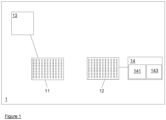
- embodiments of the present invention include a sonar system 1.
- the sonar system 1 includes a transmitter (which may be a plurality of transmitter devices or elements which may be arranged in an array (known as a transmit array 11)) and an array of receivers (known as a receive array 12).
- the receive array 12 and the transmit array 11 may be provided by the same array of transmitter-receiver devices or elements, or the receive array 12 and transmit array 11 may be separate and distinct arrays of devices or elements.
- the receive array 12 and/or the transmit array 11 (or the combined receive-and-transmit array) may be an FxG device of element array, wherein F and G are both greater than one and, in some embodiments, F may be equal to G (such that the array is a square array). Therefore, discussion herein as to the number of elements or devices in the receive 12 or transmit arrays 11 may apply, in some embodiments, to other of the receive 12 or transmit arrays 11 as well.
- the receive array 12 may be positioned in a grid-like formation with the receivers in a first plane and the transmitter (e.g. the transmit array 11) in a second plane (in some embodiments, the first and second planes are the same plane).
- Such an array may be referred to as a 2D array because the receivers are in a common plane.
- the transmitter e.g. the transmit array 11
- the first and second planes may be 5-10cm (e.g. 8-10cm) apart in some embodiments.
- one or both of the first and second planes is substantially flat but in other embodiments is curved.
- the receive array 12 comprises a forty eight by forty eight array of receivers giving a total of two thousand three hundred and four receivers in the receive array 12.
- Each receiver in the receive array 12 may be referred to as a receive element and may be a polyvinylidene difluoride (PVDF) piezoelectric device.
- PVDF polyvinylidene difluoride
- Other sizes of array are envisaged; however, for ease of explanation, a forty eight by forty eight receive array 12 is used herein as an example.
- the receive array 12 has a width of about 20cm and a height of about 20cm. It will be appreciated that the explanation of the operation of aspects of the invention will apply to other sizes of receive array 12 with appropriate scaled modifications to the calculations and hardware requirements.
- the transmitter e.g. the transmit array 11
- the receive array 12 is configured to receive the sound wave (reflected from an object).
- the transmitter (e.g. the transmit array 11) and receive array 12 are generally spaced apart from each other.
- the transmitter (e.g. the transmit array 11) and receive array 12 are housed as a single unit in one housing (for example, in a transducer head of the sonar system 1).
- the transmitter (e.g. the transmit array 11) and the receive array 12 may be generally located close to each other to reduce parallax errors.
- the transmit array 11 and receive array 12 are the same array.
- a plurality of transmitters e.g. transmit arrays 11
- receive arrays 12 may be provided.
- the pluralities may be in respective transmitter-receive array 11,12 pairs - each pair being housed in one housing, for example, but not necessarily the same housing as another pair (which may be in a separate housing).
- the sonar system 1 is configured such that the transmitter (e.g. the transmit array 11) transmits sound waves into a body of water and the receive array 12 receives reflected sound waves from the body of water.
- the transmitter e.g. the transmit array 11
- the transmitter may be configured to transmit sound waves in the form of a chirp signal (i.e. using chirp modulation or linear frequency modulation).
- the transmitter e.g. the transmit array 11
- the sonar system 1 is configured to be at least partially submerged in the body of water during use.
- at least part of the sonar system 1 e.g. the transmitter 11 and receive array 12
- a vessel i.e. a ship, boat, or submarine - or may be towed behind such a vessel.
- Other parts of the sonar system 1 may be located separately - e.g. at a sonar station within the vessel or at a remote location (which may be another vessel or a land-based facility).
- At least part of the sonar system 1 may be provided as part of an installation which may be part of a vessel or which may be a land-based installation or which may be located in an aircraft, for example.
- the transmitter e.g. the transmit array 11
- the receive array 12 may be coupled in electrical communication with receive array circuitry 14.
- the transmitter circuitry 13 is configured to drive the operation of the transmitter or transmitters (e.g. the transmit array or arrays 11) to output a sound wave in a predetermined manner - for example, as a series of pulses or pings.
- the or each transmitter e.g. the transmit array 11
- the or each transmitter is driven to output an acoustic signal with an operating frequency (i.e. a carrier frequency) which may be an operating frequency of about 375kHz (or any other suitable operating frequency).
- the operating frequency is between about 10 and about 1000 kHz.
- the operating frequency is between about 20 and about 500 kHz.
- the operating frequency is between about 80 and about 500 kHz.
- the transmitter circuitry 13 may be configured to drive the operation of the transmitter or transmitters (e.g. the transmit array or arrays 11) to output sound in the form of a chirp signal (i.e. using chirp modulation or linear frequency modulation) or a continuous waveform signal.
- the transmitter may, as described herein, be an array (the transmit array 11) and, in some embodiments, each transmitter device or element in the transmit array 11 may comprise a PVDF piezoelectric device (or at least one of the transmitters 11 is a PVDF piezoelectric device).
- PVDF piezoelectric devices have a high bandwidth and, therefore, are capable of outputting the acoustic signal which is less distorted than may be the case with conventional devices. This, in turn, means that the operation of the array of transmitter devices or elements can be controlled accurately.
- each transmitter device or element of the transmit array 11 may each comprise a respective disc of conductive material, such as copper, over which there may be provided a PVDF film (which may be around 100 ⁇ m thick).
- the disc of conductive material may be provided on a substrate - such as a printed circuit board.
- the PVDF film may cover a plurality of discs of conductive material which may each, therefore, define a respective transmitter 11.
- each conductive disc may form both a receive element and a transmitter device or element.
- the transmitter circuitry 13 is configured to control the operation of the transmitter devices or elements (i.e. of the transmit array 11) in order to generate different shapes and/or directions of acoustic beam of acoustic signal. Therefore, in some embodiments, consecutive pulses of acoustic signal output by the transmitter devices or elements (i.e. by the (e.g. the transmit array 11) may form a beam of a different shape and/or direction.
- a first beam pulse shape output by the transmitter devices or elements is a pulse suitable for one of bathymetry, sector scanning, and side scan sonar.
- a second beam pulse shape output by the transmitter devices or elements immediately after the first beam pulse, is a pulse suitable for another one of bathymetry, sector scanning, and side scan sonar.
- the transmitter devices or elements are controlled by the transmitter circuitry 13 to output an acoustic signal which forms a beam in the form of a cone, which may be a 50° cone. In some embodiments, the transmitter devices or elements (i.e. the transmit array 11) are controlled by the transmitter circuitry 13 to output an acoustic signal which forms a beam in the form of a column or spotlight-like beam. In some embodiments, the transmitter devices or elements (i.e. the transmit array 11) are controlled by the transmitter circuitry 13 to output an acoustic signal in the form of parametric pulses - which may be used for seabed penetration (e.g. sub-bottom profiling (SBP)).
- SBP sub-bottom profiling
- the transmitter devices or elements are controlled by the transmitter circuitry 13 to output an acoustic signal in the form pulses which are usable for measuring the speed of motion of the sonar system 1 and, therefore, in some embodiments, the vessel to which the sonar system 1 is mounted - these may include Doppler velocity log (DVL) and correlation velocity log pulses.
- DVD Doppler velocity log
- the transmit array 11 comprises an array of 5632 transmitter devices or elements.
- PVDF piezoelectric devices Compared to some conventional transmitter devices or elements, PVDF piezoelectric devices require a relatively high voltage to drive their operation for a given power of output of acoustic signal (i.e. acoustic sonar signal).
- acoustic signal i.e. acoustic sonar signal
- the transmitter devices or elements of the transmit array 11 may, in some embodiments, be coupled to a transmitter drive circuit 131 of the transmitter circuit 13 (see figure 6 , for example).
- the transmitter drive circuit 131 may include one or more digital-to-analog converters 132 (or, for example, a direct digital synthesiser (DDS), such as the AD9837 device from Analog Electronics) which are configured to drive the operation of one or more of the transmitter devices or elements.
- DDS direct digital synthesiser
- the transmitter drive circuit 131 is configured to drive the operation of each of the transmitter devices or elements of the transmit array 11 independently.
- the transmitter drive circuit 131 is configured to drive the operation of one or more groups of transmitter devices or elements of the transmit array 11 in unison - with each transmitter device or element of each respective group being driven together.
- each transmitter device or element is coupled to be driven by a respective digital-to-analog converter 132 of the transmitter drive circuit 131 and, in some embodiments, a single digital-to-analog converter 132 is configured to drive a group of transmitter devices or elements.
- the or each digital-to-analog converter 132 may be configured to output a respective transmit analog signal to a respective amplifier 133 of the transmitter drive circuit 131.
- the transmitter drive circuit 131 may include one or more amplifiers 133 which are configured to receive respective transmit analog signals from the analog-to-digital converter or converters 132 and to output respective amplified transmit signals to the or each transmitter device or element of the transmit array 11 to drive the operation thereof.
- the or each digital-to-analog converter 132 is configured to receive a transmit digital signal and to convert the transmit digital signal into an transmit analog signal output.
- the transmit digital signal may be received from a controller 15 of the sonar system 1, which may be a controller 15 of the transmitter circuitry 13 (e.g. of the transmitter drive circuit 131).
- the controller 15 may include one or more processors (e.g. microprocessors) which are configured to output one or more transmit digital signals to the or each digital-to-analog converter 132.
- the controller 15 may be configured to control one or more aspects of the operation of the receive array circuitry 14. In some embodiments, the controller 15 may be configured to operate the transmitter drive circuit 131 asynchronously with respect to the receive array circuitry 14.
- the controller 15 may be configured to disconnect one or more parts of the receive array circuitry 14 from the receive array 12 when the transmit array 11 is transmitting (e.g. when the transmitter drive circuit 131 is outputting a signal or signals (which may be the amplified transmit signal or signals) to drive the operation of the transmitter devices or elements of the transmit array 11.
- channel circuitry 141 and/or beamforming circuitry 143 of the receive array circuitry 14 is the one or more parts which are disconnected. In this sense, 'disconnection' means disconnection from electrical communication.
- the disconnection of at least part of the receive array circuitry 14 in this manner helps to reduce the risk of damage to the receive array circuitry 14 when the relatively high voltage signal(s) to drive the transmit array 11 is output to the transmitter devices or elements.
- the disconnection of at least part of the receive array circuitry 14 allows close placement of the receive array 13 and the transmit array 11, with reduced risk of damage to the receive array circuitry 14. Indeed, the disconnection may allow, as described herein, the receive array 13 and transmit array 11 to be provided as the same array of devices or elements.
- Disconnection of at least part of the receive array circuitry 14 may be achieved by the use of one or more isolation switch devices 142, which may form part of the receive array circuitry 14 and/or the transmitter drive circuit 131.
- the isolation switch devices 142 may include a respective isolation switch device 142 associated with each receive element of the receive array 12 or, in some embodiments, a respective isolation switch device 142 may be associated with a group of receive elements of the receive array 12. Accordingly, the or each isolation switch device 142 may be configured to couple, selectively, the associated receive element(s) of the receive array 12 with the one or more parts of the receive array circuitry 14 - as described herein.
- the isolation switch devices 142 may include a respective isolation switch device 142 associated with each transmitter device or element of the transmit array 11 or, in some embodiments, a respective isolation switch device 142 may be associated with a group of transmitter devices or elements of the transmit array 11. Accordingly, the or each isolation switch device 142 may be configured to couple, selectively, the associated transmitter device or element of the transmit array 11 with the one or more parts of the transmitter drive circuitry 131. The or each isolation switch 142 associated with at least one transmitter device or element may be operated asynchronously with respect to the operation of the or each isolation switch 142 associated with at least one receive element of the receive array 12. This operation of the or each isolation switch 142 may be controlled by the controller 15.
- the or each isolation switch 142 includes a respective active switch device - such as a field effect transistor.
- the or each isolation switch 142 is a discrete electronic component (e.g. instead of multiple isolation switches 142 being provided in a single integrated circuit).
- the or each isolation switch 142 is provided on the opposing side of a substrate (as described above) to the transmitter(s) 11 and/or receive elements. This may provide a compact construction.
- each element of the receive array 12 is also an element of the transmit array 11.
- the receive array circuitry 14 is configured to receive one or more signals from the receivers of the receive array 12 and to pre-process those signals - either for use in their pre-processed form or for further processing to occur.
- the one or more signals from the receivers are generated by the receivers in response to detected sound waves at the receivers. Accordingly, each of the one or more signals is representative of a sound wave detected by a receiver of the receive array 12.
- receive array data Collectively, the information carried by the one or more signals is referred to herein as receive array data.
- the one or more signals from the receive array 12 are typically each analogue signals.
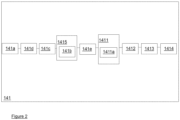
- the receive array circuitry 14 includes channel circuitry 141 and beamforming circuitry 143 for pre-processing the receive array data.
- the or each analogue signal is provided to the channel circuitry (or channel 'boards') 141 which may, in turn, comprise various filters, amplifiers, and other circuit elements including an analogue-to-digital converter 1411.
- the circuit elements of the channel circuitry 141 form channels for the or each signal on which they act.
- the analogue-to-digital converter 1411 may comprise an array of analogue-to-digital converter devices 1411a such that the or each analogue signal may be converted by a respective analogue-to-digital converter device 1411a into a respective digital signal.
- Each analogue-to-digital converter device 1411a may form part of a respective channel, as mentioned above. As such each digital signal may be described as 'channel data' on which further processing is performed.
- the I/Q demodulator 1412 may operate on a first set of samples of signals from the receive array 12 to determine the in-phase component, 'I', and a second set of samples of signals from the receive array 12 to determine the quadrature component, 'Q'.
- the demodulated channel data may then be passed to a low pass filter 1413 and then may be passed to a decimator 1414 which decimates (or subsamples) the channel data to reduce the effective sampling rate - to reduce computational overheads in the beamforming circuitry 143 and later processing stages (if applicable).
- the digital output signals from the channel circuitry 141 may be provided from the channel circuitry 141 to the beamforming circuitry 143 (or beamforming 'boards').
- the beamforming circuitry 143 is configured to process the digital data it receives from the channel circuitry 141 in accordance with conventional beamforming techniques so as to identify data within the received data which relates to specific narrow beams within the receive array data. This data can then be analysed to determine the location of one or more objects with respect to the sonar system 1 or a part thereof (for example, the seabed, a vessel, or fish).
- the beamforming circuitry 143 may be configured to process the digital data it receives from the channel circuitry 141 to identify data which relates to a one hundred and twenty eight by one hundred and twenty eight array of beams - although other array sizes are possible in other embodiments.
- a minimum sampling frequency would be understood to be 1.5M samples/s (i.e. for each of the samples for the in-phase and quadrature components, a sampling rate of 750kHz would be used).
- there is oversampling in order to allow for additional filtering to be performed or to accommodate the possibility of higher operating frequencies (e.g. a rate of 2M samples/s allows an operating frequency as high as 500kHz).
- the samples are converted by a similar analogue-to-digital converter to output digital words of 12-bit length at a rate of 55.3GBits/s for a forty eight by forty eight receive array 12 (which collects one set of samples for determining the in-phase component and another set of samples for determining the quadrature component), for example.
- This sampled data is then I/Q demodulated with an effective sampling frequency of 1MHz (which is the Nyquist sampling rate for a signal with a frequency of 500kHz).
- This data is then low-pass filtered and sub-sampled by a factor of 12 to provide an effective sampling frequency of 75kHz (which is the Nyquist sampling rate for a signal with a frequency of 37.5kHz).
- an output from the channel circuitry may be in the form of 12-bit digital words output at a rate of 75k samples/s for each data channel (i.e. 2.07Gbits/s for a forty eight by forty eight receive array 12).
- This provides a range resolution of 2cm (e.g. for a continuous wave signal or may be greater for a chirp signal).
- the data output by the channel circuitry is just 1/13 of the data available after the initial sampling and digitisation.
- outputs from the receive array 12 would need to be sampled at, at least, the Nyquist sampling rate (i.e. double the maximum frequency of the analogue signal (i.e. the operating frequency)). So, for example, a sampling rate of 750kHz would be required for a 375kHz operating frequency.
- some conventional versions of the present technology may use a substantially conventional sampling technique - sampling the outputs from the receive array 12 at, at least, the Nyquist sampling rate
- some such conventional, modified, or novel sonar systems achieve identical or substantially identical results with a sampling frequency which is determined by the bandwidth of the analogue signal.
- the bandwidth relates only to the required range resolution. Therefore, for a range resolution of 1cm with a 375kHz operating frequency, there is a required bandwidth of 75kHz and so a Nyquist sampling rate of 150kHz, where the bandwidth required for that range resolution is c/(2d), wherein 'c' is the speed of sound in water (about 1500m/s) and 'd' is the range resolution in metres.
- a sampling rate for the outputs from the receive array 12 of 150kHz would be sufficient to provide substantially all the useful data to the beamforming circuitry 143 (although, in some embodiments, elements such as the decimator 1414 could be omitted as sub-sampling is not necessarily needed in accordance with embodiments).
- the analogue-to-digital converter 1411 may include one or more multiplexed analogue-to-digital converter devices 1411a which are each configured to convert more than one analogue signal (of the receive array data) into respective corresponding digital signals (the channel data). As such, there may be fewer analogue-to-digital converter devices 1411a than the number of receivers in the receive array 12.
- the channel circuitry 141 may include an array of pre-amplifiers 141a which are each configured to amplify a respective one of the analogue signals.
- the channel circuitry 141 may further include an array of switch devices 141b (such as FET switch based devices) which are each configured to provide selectively one of two or more of the analogue signals to one of the analogue-to-digital converter devices 1411a. Accordingly, the array of switch devices 141b provide multiplexing circuitry 1415 configured to provide a plurality of the analogue signals selectively to a single of the analogue-to-digital converter device 1411a.
- switch devices 141b such as FET switch based devices
- each of the forty eight receive elements in each row of the receive array 12 may be sampled in turn, from one end of the array to the opposing end of the array - working up (or down) the columns of the receive array 12.
- Each column in such an example, may be provided with its own analogue-to-digital converter device 1411a.
- such an arrangement is provided but there are a different number of rows and columns of receive elements in the receive array 12.
- sampling is performed in a sequence from the centre of the receive array 12 outwards instead.
- the channel circuitry 141 may further include an array of band pass filters 141c which is connected between the pre-amplifiers 141a and the switch devices 141b.
- Each of the band pass filters 141c is configured to receive a one of the analogue signals (of the receive array data) and to apply a band pass function on that signal which is then passed towards a switch device 141b of the multiplexing circuitry 1415.
- the positioning of the band pass filters 141c between the pre-amplifiers 141a and the switch devices 141b may help to reduce the risk of propagation delays through the band pass filters 141c meaning that there is insufficient setup time for the analogue-to-digital converter devices 1411a - which would lead to interference of the samples and inaccurate digital signals being output by the analogue-to-digital converter devices 1411a.
- each band pass filter 141c may include a plurality of filters arranged in series.
- the further switch devices 141d may be used, in some embodiments, to schedule the outputs of the relatively slow band pass filters 141c to the analogue-to-digital converter devices 1411a. As will be appreciated, in embodiments with further switch devices 141d, there may be fewer band pass filters 141c compared to the number of pre-amplifiers 141a.
- the receive array 12 may be configured as a grid of receivers arranged in rows and columns - as discussed above.
- the multiplexing may be achieved by sampling the analogue signals from the columns of receivers simultaneously but sampling each the analogue signals from each row of all columns slightly later than the previous one.
- the sampling may start at the centre of the receive array 12 and proceed in an outward direction with successive samples.
- the sampling may be performed by rows or columns instead - in a similar manner to the sampling described above by the multiplexing circuitry 1415. Two successive samples provided to the same band pass filter 141c would be selected to ensure that the propagation delay from the receiver to the further switch devices 141d is greater than the propagation delay (or group delay) through the band pass filters 141c.
- the multiplex circuitry 1415 and further switch devices 141d may operate independently of each other.
- the channel circuitry 141 may further include an array of time varying gain (TVG) amplifiers 141e.
- the TVG amplifiers 141e may be located (i.e. connected) between the switch devices 141b (i.e. the multiplexing circuitry 1415) and the analogue-to-digital converter devices 1411a (i.e. the analogue-to-digital converter 1411). Therefore, as will be appreciated, there may be fewer TVG amplifiers 141e than the number of receivers in the receive array 12 (as achieved by the multiplexing described above).
- the TVG amplifiers 141e are configured to compensate for the attenuation of a sound signal as it passes through the body of water.
- the TVG amplifiers 141e may, therefore, be configured to receive a user input to fine tune the gain of the TVG amplifiers 141e to accommodate different attenuations when in use.
- variable gain amplifier such as the AD8338 device, by Analog Devices, Inc, is one possible example of a device which could be used to implement each TVG amplifier 141e.
- the array of TVG amplifiers 141e may be connected between receive array 12 and the multiplexing circuitry 1415, instead of between the multiplexing circuitry 1415 and the analogue-to-digital converter 1411.
- the array of TVG amplifiers 141e may be connected to receive signals from the band pass filters 141c (or other component connected between the band pass filters 141c and the array of TVG amplifiers 141e) or may be connected to send signals to the band pass filters 141c (or other component connected between the array of TVG amplifier 141e and the band pass filter 141c).
- the array of pre-amplifiers 141a may be connected between the multiplexing circuitry 1415 and the analogue-to-digital converter 1411 instead of between receive array 12 and the multiplexing circuitry 1415.
- the two stages of multiplexing may be useful in embodiments in which the TVG amplifiers 141e constrain the number of multiplexed signals that can be handled.
- TVG amplifiers 141e allow echoes (i.e. reflected sound signals) from distant objects to be amplified more than echoes from closer objects.
- fixed gain amplifiers may be used instead of TVG amplifiers 141e, connected in much the same manner (see 141e in figure 2 , for example).
- the fixed gain amplifiers may be connected between the switch devices 141b (i.e. the multiplexing circuitry 1415) and the analogue-to-digital converter devices 1411a (i.e. the analogue-to-digital converter 1411) or between the receive array 12 and the multiplexing circuitry 1415.
- Each of the fixed gain amplifiers may be configured to receive a signal from the switch devices 141b or receive array 12, as the case may be, in succession.
- Each of the fixed gain amplifiers may be configured to amplify each received signal in accordance with a fixed gain for that fixed gain amplifier.
- the fixed gain amplifiers may be configured to output a plurality of amplified signals for each received signal, each of the plurality of amplified signals having been amplified by a predetermined amount, i.e. gain, according to which of the fixed gain amplifiers output generated the amplified signal.
- the analogue-to-digital converter 1411 may be configured to determine which of the amplified signals to use based on the operating range of the analogue-to-digital converter 1411 (e.g. the range of signal voltage that the analogue-to-digital converter 1411 can convert).
- the analogue-to-digital converter 1411 may be further configured to output, with the digital signals, an indication of which amplifier of the fixed gain amplifiers was used.
- This output may be in the form of a scaling factor, which may be a digital word (e.g. a byte) associated with the digital signal or a part of the signal.
- Unused amplified signals from the fixed gain amplifiers may be discarded.
- the dynamic ranges of the fixed gain amplifiers may overlap.
- the analogue-to-digital converter devices 1411a may, in some embodiments, output a digital signal with an effectively larger dynamic range and number of bits.
- the dynamic range may be about 96dB. Therefore, in the above example the ranges of the digital signals output by the fixed gain amplifiers with 82dB and 154dB gains will overlap for 10dB (approximately 2 bits). Similarly, the ranges of the digital signals output by the fixed gain amplifiers with 10dB and 82dB gains will overlap by 24dB (approximately 4 bits). Effectively, the 16 bit analogue-to-digital converter device 1411a has been used to create a 42 bit, 250dB digital signal.
- each analogue-to-digital converter device 1411a may be associated with (i.e. configured to receive an amplified signal directly or indirectly from) a plurality of fixed gain amplifiers with respective different gains (i.e. a group of fixed gain amplifiers). In some embodiments, each analogue-to-digital converter device 1411a is associated with three such fixed gain amplifiers. The gains of each group of fixed gain amplifiers for a particular analogue-to-digital converter device 1411a may have the same gains as each other group of fixed gain amplifiers.
- multiplexing as used herein is a reference to the sequencing of the delivery of the analogue signals to another circuit component - be it the analogue-to-digital converter 1411 for sampling or to the band pass filters 141c.
- the multiplexing (or sequencing) is in accordance with a predetermined scheme - as discussed above.
- the I/Q demodulator 1412 may operate, in some embodiments, by using signals from the receive array 12 which are sampled (and converted into digital signals) by the analogue-to-digital converter 1411 at a sampling frequency which is twice the bandwidth of the analogue signal or twice (or more) of the operating frequency of the sonar system 1 - depending on the sampling technique used, as described herein.
- the I/Q demodulator 1412 may obtain a cosine and a sine component of the output sound wave from the transmitter 11 at substantially the moment (i.e. instant) each sample is taken by the analogue-to-digital converter 141.
- the digital signal output by the analogue-to-digital converter 141 is then used by the I/Q demodulator to determine a value for the in-phase and quadrature components of the signal by multiplying the digital signal by the cosine component of the sound wave to give the in-phase component and by the -sine component of the sound wave to give the quadrature component.
- the I/Q demodulator determines a value for the in-phase and quadrature components of the signal by multiplying the digital signal by the cosine component of the sound wave to give the in-phase component and by the -sine component of the sound wave to give the quadrature component.
- the beamforming circuitry 143 may include a processor 1431 which is configured to perform one or more operations on the digital channel data received from the channel circuitry 141.
- the processor 1431 may be a dedicated or general purpose processor and may be a Field Programmable Gate Array device or other programmable logic device.
- the beamforming circuitry 143 may be configured to use spectral decomposition of the aperture field (SDAF) techniques to generate image data from the digital channel data received from the channel circuitry 141.
- SDAF aperture field
- the SDAF technique is an example of a pseudo-inverse technique and embodiments of the invention could employ pseudo-inverse techniques other than the SDAF technique.
- multiplexing in the manner described means that not all samples are simultaneously collected.
- which samples are collected simultaneously as part of the multiplexing process e.g. all column of receivers being simultaneously sampled but each row of all columns being sampled later than the preceding row
- the effect of the delays can be predicted, quantified, and (if necessary) compensatory action can be taken accordingly.
- the effect of the delays will be as if the pitch of the receive array 12 had been altered.
- 'c' is the data representing the image of the object which has reflected the sound waves and is what the beamforming circuitry 143 seeks to determine (i.e. a vector of the scattering elements' reflectivity of size Mx1).
- 's' is what is measured by the receive array 12 and 'U' is known from the design of the sonar system 1.
- the vector 's' is composed of N Fourier transforms of the digital channel data. In some instances neither matrix 'U' nor vector 's' are required - for example, in embodiments in which a fixed frequency pulse is being transmitted and I/Q demodulation of the received waveform has been performed.
- c ⁇ U H UU H + s
- H the complex conjugate and transpose
- + the pseudo-inverse
- the propagation matrix elements comprise the Fourier transform of the outgoing sound pulse, and the Fourier transform of the delay incurred by its travel to and from the reflector (in the range cell being sensed).
- the delay caused by the multiplexing process can, therefore, be taken into account within this equation by adjusting the distance
- UU H the pseudoinverse (UU H ) + does not need to be calculated as the product of U and U H is a Hermitian matrix. Therefore, the inverse of UU H can be taken to be the diagonal eigenvalue matrix of UU H , where each eigenvalue has been inverted.
- the multiplexing and the introduced delay also has the effect of decreasing the grating lobe performance - the receivers in the receive array 12 appear further apart and the grating lobes, therefore, are closer together.
- the multiplexing is designed carefully - e.g. in accordance with the technique described above - then the effect is limited to the rows of receivers. To compensate, therefore, the rows of receivers may be positioned closer together in the receive array 12.
- the sample rate may be greater than twice the desired bandwidth of the signal for a given range resolution.
- the signal bandwidth has been restricted to 37.5kHz to achieve the desired range resolution, so the Nyquist sampling rate to avoid spatial aliasing would be 75kHz.
- some embodiments of the present invention may allow a sampling frequency to be used which is substantially equal to or greater than the required bandwidth of the analogue signals (for the desired range resolution) but which is less than twice the carrier frequency (i.e. the operating frequency) of the sonar system 1.
- the sampling frequency may be equal to or greater than twice the operating frequency of the sonar system 1.
- the degree of multiplexing which is possible will depend on the desired range resolution - a greater range resolution will mean more bandwidth is required and the degree of multiplexing must be lower, for a given maximum sampling rate.
- the above described I/Q demodulator 1412 may be a FIR Hilbert Transform filter - configured to demodulate the digital channel data into digital output signals which include both complex and real parts.
- the FIR Hilbert Transform filter (compared to the conventional I/Q demodulator) would allow further reductions in the sampling frequency. This is because both the in-phase and quadrature components can be determined, using the FIR Hilbert Transform filter, from a single set of samples - it is not necessary to obtain a first set to determine the in-phase component and a second set to determine the quadrature component.
- multiplications by cosine and sine that are part of conventional I/Q demodulation may be avoided.
- elements for the channel circuitry 14 may be provided as on a printed circuit board 21 on which the receiver array 12 is mounted. These elements may include, for example, the pre-amplifiers 141a, and the switches 141b.
- the analogue-to-digital converter 141 may be provided on a separate printed circuit board 22 and the beamforming circuitry 13 may also be provided on a separate printed circuit board 23.
- the circuit boards 21,22,23 may be arranged in a sandwich formation, with the circuit board 22 carrying the analogue-to-digital converter 141 mounted between the circuit board 21 carrying the receiver array 12 and the circuit board 23 carrying the beamforming circuitry 13. This provides a very compact construction. These circuit boards 21,22,23 may then be placed in a single housing 30.
- Such housings 30 are conventionally filled with a liquid (such as Fluorinert(RTM)) to provide desirable heat transfer characteristics between the housed components and the housing 30 - to allow heat to be dissipated quickly.
- a liquid such as Fluorinert(RTM)
- RTM Fluorinert
- liquids may be used for this purpose which have lower heat transfer performance - such as vegetable oils or hydraulic fluid.
- the housing 30 may be generally cylindrical. In some embodiments, a height of the housing 30 may be less than about 30cm (e.g. about 20cm) and the housing 30 may have a diameter of less than about 30cm (e.g. about 20cm). In some embodiments, the housing is formed of aluminium. In some embodiments, the receive 11 and/or transmit 12 arrays (or combined array) may be coated in a urethane layer.
- a method of retrofitting aspects of the invention to an existing sonar system 1 may include the replacement of printed circuit boards of the existing sonar system 1 (or other circuitry) with printed circuit boards 21,22,23 (or other circuitry) according to embodiments of the invention.
- the channel circuitry of an existing sonar system 1 may be replaced with the above described channel circuitry 14.
- the modified circuitry could then be housed in the housing 30 of the existing sonar system 1.
- the band pass filters 141c may be replaced by respective low pass filters - which may provide sufficient filtering for some applications.
- the above description is to be read accordingly and relates equally to such embodiments.
- the multiplexing (and therefore delaying) of the signals from the receive array 12 uses a generalisation that each part of the sound wave pulse is reflected exactly the same by any target element - changes in phase caused by a delay may be accommodated during I/Q demodulation.
- the transmitter circuitry 13 may be configured to drive the operation of the transmitter 11 or transmitters 11 to output a sequence of pulses or pings. Accordingly, the or each transmitter 11 may be configured to output a sequence of pulses or pings.
- the sequence of pulses or pings comprises groups of pulses or pings, with each group may include one or more pulses or pings.
- at least one group includes at least one pulse or ping which is of a different length (i.e. duration). Accordingly, one group may be different to another group. The difference in groups allows the receive array circuitry 14 to distinguish one group from another group of pulses or pings which are received by the receive array 12.
- the use of different groups of pulses or pings enables consecutive groups of pulses and pings to be output by the transmitter 11 or transmitters 11 (and/or driven by the transmitter circuitry 13) at a higher rate than would otherwise be possible because the receive array 12 and receive array circuitry 14 can distinguish one group from another group. This, in turn, allows a better range resolution to be achieved.
- a first group of pulses or pings may comprise a first pulse or ping of half the length normally used for the desired range resolution (a short pulse or ping), followed by a gap of the same length, followed by a pulse or ping of the length normally required for the desired range resolution (a long pulse or ping).
- a second of the group of pulses or pings may comprise a single pulse of the length required for the desired range resolution.
- the receive array 12 may receive pulses or pings reflected from one or more objects.
- the receive array circuitry 14 may be further configured to analyse the received pulses or pings. If the first received group comprises two pulses or pings with a gap therebetween, then this is determined to be the first group of pulses or pings.
- the second received group may comprise a single pulse or ping which is determined to be the second group of pulses or pings. Receipt of the first group of pulses or pings will mean that the range resolution for the range determined by the time of flight (i.e. the time between transmission and reception) will be the range resolution associated with the first group of pulses or pings. Receipt of the second group of pulses or pings gives a time of flight at a higher range resolution than the first group.
- the time between the transmission of the first and second groups of pulses or pings is known (for example, equal to the length of time required for the pulse or ping to travel one metre in water), and only one of the groups is received (e.g. the second group), then this implies that the other group (e.g. the first group) has not been received. If the received group is the second group, then the range resolution may be better than would otherwise be the case even though the first group was not received.
- the time (i.e. gap) between the initial short pulse or ping and the later long pulse or ping of the first group, along with the length of the short and long pulse may be varied to achieve different range resolutions for a given sample rate.
- the first pulse or ping may be the long pulse or ping and the subsequent pulse or ping may be the short pulse or ping.
- the receive array circuitry 14 may be configured to monitor the time between received pings or pulses, the duration of each received ping or pulse, and sequence of received pings or pulses.
- the receive array circuitry 14 may be configured to distinguish one group of pulses or pings from another group of pulses or pings based on one or more of the time between received pings or pulses, the duration of each received pulse or ping, and the sequence of the received pulses or pings.
- an object from which a group of pings or pulses are reflected is at a range such that a second or subsequent pulse or ping of the group is not detected (i.e. it is reflected but falls between samples), then this gives information about the range of the object.
- a sample from which a first pulse or ping of the group may be detected could be a sample of that pulse or ping at any point along the length of the pulse or ping. Whether or not the second or subsequent pulse or ping is detected may allow, in some embodiments, the point of detection along the length of the first pulse or ping to be determined or inferred with greater accuracy - thus giving more information about the range of the object.
- the use of a group of pulses or pings may allow not only the time of flight between transmission of a first pulse/ping and the receipt of the reflected first pulse/ping to be used to determine range of an object, but the subsequent pulse(s) or ping(s) may be used to make the measured time of flight to be more accurate (and hence also to refine the determined range) - by determining to a greater accuracy when the first pulse or ping of the group was, in fact, received.
- the receive array circuitry 14 and the transmitter circuitry 13 may be configured to communicate such that the receive array circuitry 14 is provided with information identifying the groups of pings or pulses being transmitted - this information may include, for example, transmission times, pulse or ping duration, gap duration, and sequence information for the pulses or pings of each group.
- the groups of pings or pulses are selected substantially at random. In embodiments, the groups of pings or pulses are not predefined - in such embodiments, one or more of the duration of each ping or pulse, the duration of the gap between each ping or pulse, and the sequence of pings or pulses, is varied from group to group by the transmitter circuitry 13.
- a particular group may suffer from distortion to a greater extent on reflection from a particular object than another group (e.g. because of the form of the object).
- a 3D instantaneous sonar system 1 is provided.
- Many conventional sonar systems are advertised as '3D'; however, many such conventional sonar systems are, in fact, 2D sonar systems which use sophisticated post-processing software to create 3D scene representations. This may be conventionally achieved by, for example, combining successive 2D scans - usually beams that are very narrow in the along-track direction, but wide in the across-track direction.
- the collection of 2D scan data sets can be combined by means of conventional postprocessing to give a 3D data set. If the conventional sonar system were mounted on a vessel that moved at a constant speed without pitch, roll or heading variations, this would be reasonably easy.
- Some embodiments of the present invention may provide an instantaneous 3D sonar system 1 which may cover a 50° ⁇ 50° area with each ping or pulse. Therefore, for a 125m depth, there would be a footprint of 100m ⁇ 100m. Accordingly, in some embodiments, to cover 100m ⁇ 100m of seafloor, one ping or pulse is all that would be required.
- far fewer pings or pulses would be used over a given period (e.g. to obtain an accurate bathymetry dataset).
- some embodiments may provide images of an area of interest substantially instantly, rather than taking several minutes, or hours, to obtain and then longer to process. This may be an advantage in situations which are dynamic - e.g. inspecting the underside of a moving vessel, or the quick inspection of a harbour wall from a vessel moving at 10 or 15 knots.
- Some embodiments of the invention may be configured to provide images from ahead of the current vessel position (unlike may conventional sonar systems which look straight down and survey the path taken by the vessel).
- approximately half the image data is from in front of the vessel, and around half from behind the vessel. This may be advantageous in monitoring the movement of a target of interest - such as divers, porpoises, or autonomous underwater vehicles.
- any change that takes place within the volume covered by the pings or pulses, over several pings/pulses will be more obvious to the user in real time.
- use of a sonar system 1 as described herein may reduce the requirement for complex equipment to be provided to determine the movement of the vessel during operation.
- the user may not require such a high skill or training level compared to operation of conventional sonar systems (because of the instantaneous operation of some embodiments).
- Embodiments of the present invention have been described with reference to a sonar system 1. However, it will be appreciated that these embodiments may also be applied to other acoustic imaging systems including, for example, ultrasound imaging systems.
- the vessel as described above would, in the case of an ultrasound imaging system, be the carrier of the ultrasound imaging system - which may be a wand or other handheld device, or which could take a number of different forms.
- the carrier of such embodiments may carry the receive and transmit arrays 11,12 and may be coupled to a base unit (through a wired or wireless connection) which may include one or more other components of the acoustic imaging system.
- some embodiments of the present invention relate to sonar systems, and/or to acoustic imaging systems including sonar systems, ultrasound imaging systems, and other acoustic imaging systems, and/or acoustic imaging systems not including sonar systems.
- bandwidth is a reference to the difference between the maximum and minimum frequencies between which information is required to be acquired or transmitted - in other words, the "passband bandwidth”.
Landscapes
- Engineering & Computer Science (AREA)
- Radar, Positioning & Navigation (AREA)
- Remote Sensing (AREA)
- Physics & Mathematics (AREA)
- Computer Networks & Wireless Communication (AREA)
- General Physics & Mathematics (AREA)
- Acoustics & Sound (AREA)
- Mechanical Engineering (AREA)
- Measurement Of Velocity Or Position Using Acoustic Or Ultrasonic Waves (AREA)
Claims (10)
- Eine Empfangs-Anordnungs-Schaltung (14) für ein System zur akustischen Bildgebung, das Folgendes umfasst: eine Vielzahl von Eingängen, wobei jeder Eingang so konfiguriert ist, dass er ein analoges Signal von einer Empfangseinheit einer akustischen Bildempfangsfeldanordnung (12) empfängt;einen Analog-Digital-Wandler (1411), der so konfiguriert ist, dass er analoge Signale abtastet und in entsprechende digitale Signale umwandelt; undeine Strahlformungsschaltung (143), die so konfiguriert ist, dass sie die digitalen Signale von dem Analog-Digital-Wandler (1411) empfängt und ein akustisches Bild aus den digitalen Signalen erzeugt, wobei der Analog-Digital-Wandler (1411) so konfiguriert ist, dass er eine vom Benutzer ausgewählte Bereichsauflösung empfängt und die analogen Signale mit einer Abtastrate abtastet, die auf der Grundlage einer vorgegebenen erforderlichen Bandbreite des analogen Signals bestimmt wird, wobei die vorgegebene erforderliche Bandbreite des analogen Signals auf der Grundlage der vom Benutzer ausgewählten Bereichsauflösung für das System zur akustischen Bildgebung ausgewählt wird.
- Empfangs-Anordnungs-Schaltung (14) nach Anspruch 1, wobei die Abtastrate im Wesentlichen gleich oder größer ist als das Doppelte der vorgegebenen Bandbreite des analogen Signals.
- Empfangs-Anordnungs-Schaltung (14) nach Anspruch 1 oder 2, wobei die Abtastrate weniger als das Doppelte einer Betriebsfrequenz des Systems zur akustischen Bildgebung beträgt, wobei die Betriebsfrequenz die Trägerfrequenz des analogen Signals ist.
- Empfangs-Anordnungs-Schaltung (14) nach Anspruch 3, wobei die Abtastrate ein Bruchteil der Betriebsfrequenz des Systems zur akustischen Bildgebung ist.
- Empfangs-Anordnungs-Schaltung (14) nach einem der Ansprüche 1 bis 4, die ferner einen I/Q-Demodulator (1412) umfasst, der so konfiguriert ist, dass er die digitalen Signale von dem Analog-Digital-Wandler empfängt, eine I/Q-Demodulation durchführt und die I/Qdemodulierten digitalen Signale an die Strahlformungsschaltung (143) weiterleitet.
- Empfangs-Anordnungs-Schaltung (14) nach Anspruch 5, wobei der I/Q-Demodulator einen FIR-Hilbert-Transformationsfilter verwendet.
- Empfangs-Anordnungs-Schaltung (14) nach einem der Ansprüche 1 bis 6, die ferner eine Multiplexing-Schaltung umfasst, die so konfiguriert ist, dass sie die Lieferung einer Vielzahl der analogen Signale an den Analog-Digital-Wandler (1411) gemäß einem Multiplexing-Schema sequenziert, und wobei die Strahlformungsschaltung (143) so konfiguriert ist, dass sie relative Verzögerungen zwischen Abtastungen kompensiert, die von dem Analog-Digital-Wandler (1411) erfasst werden.
- System zur akustischen Bildgebung (1) mit einer Empfangs-Anordnungs-Schaltung (14) nach einem der Ansprüche 1 bis 7.
- System zur akustischen Bildgebung (1) nach Anspruch 8, das ferner eine Empfangsanordnung (12) umfasst.
- Gefäß mit einem System zur akustischen Bildgebung (1) nach Anspruch 8 oder 9.
Applications Claiming Priority (3)
| Application Number | Priority Date | Filing Date | Title |
|---|---|---|---|
| US201462092975P | 2014-12-17 | 2014-12-17 | |
| GB1422690.6A GB2533388B (en) | 2014-12-17 | 2014-12-18 | Aspects of a sonar system |
| PCT/GB2015/054062 WO2016097747A1 (en) | 2014-12-17 | 2015-12-17 | Aspects of sonar systems or other acoustic imaging systems |
Publications (3)
| Publication Number | Publication Date |
|---|---|
| EP3234635A1 EP3234635A1 (de) | 2017-10-25 |
| EP3234635B1 true EP3234635B1 (de) | 2024-07-17 |
| EP3234635C0 EP3234635C0 (de) | 2024-07-17 |
Family
ID=57142731
Family Applications (1)
| Application Number | Title | Priority Date | Filing Date |
|---|---|---|---|
| EP15813553.3A Active EP3234635B1 (de) | 2014-12-17 | 2015-12-17 | Aspekte von sonarsystemen oder anderen akustischen bildgebungssystemen |
Country Status (6)
| Country | Link |
|---|---|
| US (1) | US11300669B2 (de) |
| EP (1) | EP3234635B1 (de) |
| AU (2) | AU2015365600A1 (de) |
| GB (1) | GB2533388B (de) |
| WO (1) | WO2016097747A1 (de) |
| ZA (1) | ZA201704258B (de) |
Families Citing this family (19)
| Publication number | Priority date | Publication date | Assignee | Title |
|---|---|---|---|---|
| EP3836539B1 (de) | 2007-10-10 | 2024-03-13 | Gerard Dirk Smits | Bildprojektor mit verfolgung von reflektiertem licht |
| US12025807B2 (en) | 2010-10-04 | 2024-07-02 | Gerard Dirk Smits | System and method for 3-D projection and enhancements for interactivity |
| US9946076B2 (en) | 2010-10-04 | 2018-04-17 | Gerard Dirk Smits | System and method for 3-D projection and enhancements for interactivity |
| US9377533B2 (en) | 2014-08-11 | 2016-06-28 | Gerard Dirk Smits | Three-dimensional triangulation and time-of-flight based tracking systems and methods |
| JP6854828B2 (ja) | 2015-12-18 | 2021-04-07 | ジェラルド ディルク スミッツ | 物体のリアルタイム位置検知 |
| EP3532863A4 (de) * | 2016-10-31 | 2020-06-03 | Gerard Dirk Smits | Schnell abtastender lidar mit dynamischer voxel-sondierung |
| WO2018125850A1 (en) | 2016-12-27 | 2018-07-05 | Gerard Dirk Smits | Systems and methods for machine perception |
| JP7246322B2 (ja) | 2017-05-10 | 2023-03-27 | ジェラルド ディルク スミッツ | 走査ミラーシステム及び方法 |
| GB2566437B (en) * | 2017-07-26 | 2022-12-07 | Sezanne Marine Ltd | Systems and methods for acoustic and/or electromagnetic imaging |
| WO2019079750A1 (en) | 2017-10-19 | 2019-04-25 | Gerard Dirk Smits | METHODS AND SYSTEMS FOR NAVIGATING A VEHICLE EQUIPPED WITH A NEW MILITARY MARKER SYSTEM |
| WO2019148214A1 (en) | 2018-01-29 | 2019-08-01 | Gerard Dirk Smits | Hyper-resolved, high bandwidth scanned lidar systems |
| US11733377B2 (en) * | 2018-05-07 | 2023-08-22 | Texas Instruments Incorporated | Time of flight and code signature detection for coded ultrasonic transmission |
| US11644555B2 (en) | 2018-07-27 | 2023-05-09 | Texas Instruments Incorporated | Threshold generation for coded ultrasonic sensing |
| US11378686B2 (en) | 2018-12-26 | 2022-07-05 | Texas Instruments Incorporated | Ultrasonic echo processing in presence of Doppler shift |
| US12372643B2 (en) | 2019-01-11 | 2025-07-29 | Texas Instruments Incorporated | Coded ultrasonic sensing with staggered bursts |
| FR3106416B1 (fr) | 2020-01-17 | 2022-02-18 | Ixblue | Échosondeur paramétrique dépointable, et procédé de caractérisation d’une partie du sous-sol d’un milieu subaquatique |
| US11372320B2 (en) | 2020-02-27 | 2022-06-28 | Gerard Dirk Smits | High resolution scanning of remote objects with fast sweeping laser beams and signal recovery by twitchy pixel array |
| CN111721672B (zh) * | 2020-05-29 | 2023-02-21 | 浙江理工大学 | 基于多普勒和声呐图像技术的多相测试方法 |
| US11520042B1 (en) | 2022-02-11 | 2022-12-06 | Mythos AI Inc | Apparatus and methods for artificial intelligence bathymetry |
Citations (2)
| Publication number | Priority date | Publication date | Assignee | Title |
|---|---|---|---|---|
| US20050086013A1 (en) * | 2003-09-04 | 2005-04-21 | Couch Philip R. | Analysis of ultrasonic reflections to measure distance |
| US20090240152A1 (en) * | 2005-02-09 | 2009-09-24 | Angelsen Bjorn A J | Digital Ultrasound Beam Former with Flexible Channel and Frequency Range Reconfiguration |
Family Cites Families (36)
| Publication number | Priority date | Publication date | Assignee | Title |
|---|---|---|---|---|
| FR2109443A6 (de) * | 1970-10-16 | 1972-05-26 | Thomson Csf | |
| FR2478822A1 (fr) * | 1980-03-18 | 1981-09-25 | Thomson Csf | Systeme de detection active au moyen d'emissions multiples simultanees |
| NL8200728A (nl) * | 1982-02-24 | 1983-09-16 | Hollandse Signaalapparaten Bv | Stoorsignaalonderdrukkingseenheid voor een sonarapparaat. |
| US4821038A (en) * | 1987-11-03 | 1989-04-11 | Megapulse Incorporated | Method of and apparatus for Loran-C message communication with reduced skywave navigation location errors and the like |
| US5197037A (en) * | 1991-10-31 | 1993-03-23 | Hewlett-Packard Company | Method and apparatus for the simultaneous performance of the beam formation and scan conversion in a phased array system |
| US5482044A (en) * | 1992-01-14 | 1996-01-09 | Diasonics Ultrasound, Inc. | Direct demodulation in ultrasound instruments |
| US5230340A (en) * | 1992-04-13 | 1993-07-27 | General Electric Company | Ultrasound imaging system with improved dynamic focusing |
| KR950013122B1 (ko) * | 1993-05-24 | 1995-10-25 | 주식회사메디슨 | 초음파신호의 디지탈집속방법 및 그 장치 |
| US5793701A (en) * | 1995-04-07 | 1998-08-11 | Acuson Corporation | Method and apparatus for coherent image formation |
| US5675554A (en) * | 1994-08-05 | 1997-10-07 | Acuson Corporation | Method and apparatus for transmit beamformer |
| JPH10507936A (ja) * | 1994-08-05 | 1998-08-04 | アキュソン コーポレイション | 送信ビーム生成器システムのための方法及び装置 |
| US6356555B1 (en) * | 1995-08-25 | 2002-03-12 | Terayon Communications Systems, Inc. | Apparatus and method for digital data transmission using orthogonal codes |
| GB2329072A (en) * | 1997-09-09 | 1999-03-10 | Secr Defence | Processing of signals incident on an array |
| NO307014B1 (no) | 1998-06-19 | 2000-01-24 | Omnitech As | Fremgangsmåte for frembringelse av et 3D-bilde |
| GB9814093D0 (en) | 1998-07-01 | 1998-08-26 | Coda Technologies Ltd | Subsea positioning system and apparatus |
| GB2355529B (en) * | 1999-07-28 | 2004-01-28 | Furuno Electric Co | Signal processing method and apparatus,and sonar systems |
| US7035166B2 (en) * | 2002-10-21 | 2006-04-25 | Farsounder, Inc. | 3-D forward looking sonar with fixed frame of reference for navigation |
| US6922145B2 (en) * | 2002-05-29 | 2005-07-26 | Gregory Hubert Piesinger | Intrusion detection, tracking, and identification method and apparatus |
| US6661739B1 (en) | 2002-05-31 | 2003-12-09 | The United States Of America As Represented By The Secretary Of The Navy | Filigree electrode pattern apparatus for steering parametric mode acoustic beams |
| AU2004258175B2 (en) * | 2003-07-11 | 2009-09-17 | Teledyne Reson A/S | Systems and methods implementing frequency-steered acoustic arrays for 2D and 3D imaging |
| US8220334B2 (en) * | 2006-11-10 | 2012-07-17 | Penrith Corporation | Transducer array imaging system |
| US8499634B2 (en) * | 2006-11-10 | 2013-08-06 | Siemens Medical Solutions Usa, Inc. | Transducer array imaging system |
| US8312771B2 (en) * | 2006-11-10 | 2012-11-20 | Siemens Medical Solutions Usa, Inc. | Transducer array imaging system |
| US8656783B2 (en) * | 2006-11-10 | 2014-02-25 | Siemens Medical Solutions Usa, Inc. | Transducer array imaging system |
| RU2009145693A (ru) * | 2007-05-10 | 2011-06-20 | Астриум Лимитед (Gb) | Система обработки сигналов |
| US8295326B1 (en) | 2008-06-12 | 2012-10-23 | University Of South Florida | Digital coding scheme for data transmission |
| EP2318860A4 (de) * | 2008-08-11 | 2012-07-04 | Marport Canada Inc | Phasengesteuertes softwaredefiniertes breitband-multifunktionssonarsystem und verfahren |
| US8570405B2 (en) * | 2010-08-11 | 2013-10-29 | Inview Technology Corporation | Determining light level variation in compressive imaging by injecting calibration patterns into pattern sequence |
| WO2012049124A2 (en) * | 2010-10-11 | 2012-04-19 | B-K Medical Aps | Methods and systems for producing compounded ultrasound images |
| US8952764B2 (en) * | 2012-03-09 | 2015-02-10 | Raytheon Company | High-frequency, high-speed precision digital bi-phase modulator and method for bi-phase modulation |
| US9194945B2 (en) * | 2012-07-24 | 2015-11-24 | Laufer Wind Group Llc | Open loop power oscillator doppler radar |
| WO2014057234A1 (en) * | 2012-10-08 | 2014-04-17 | Mbda Uk Limited | Improvements in and relating to radar receivers |
| EP2741103B1 (de) * | 2012-12-06 | 2018-04-11 | Technion Research & Development Foundation Ltd. | Strahlformung im Frequenzbereich |
| US9577773B2 (en) * | 2014-05-06 | 2017-02-21 | Verizon Patent And Licensing Inc. | Station assisted interference measurement |
| US10209353B2 (en) * | 2015-05-19 | 2019-02-19 | Src, Inc. | Bandwidth enhancement beamforming |
| JP6909023B2 (ja) * | 2017-03-14 | 2021-07-28 | パナソニック株式会社 | レーダ装置及びレーダ方法 |
-
2014
- 2014-12-18 GB GB1422690.6A patent/GB2533388B/en active Active
-
2015
- 2015-12-17 AU AU2015365600A patent/AU2015365600A1/en not_active Abandoned
- 2015-12-17 EP EP15813553.3A patent/EP3234635B1/de active Active
- 2015-12-17 WO PCT/GB2015/054062 patent/WO2016097747A1/en not_active Ceased
- 2015-12-17 US US15/537,159 patent/US11300669B2/en active Active
-
2017
- 2017-06-22 ZA ZA2017/04258A patent/ZA201704258B/en unknown
-
2020
- 2020-04-14 AU AU2020202507A patent/AU2020202507B2/en active Active
Patent Citations (2)
| Publication number | Priority date | Publication date | Assignee | Title |
|---|---|---|---|---|
| US20050086013A1 (en) * | 2003-09-04 | 2005-04-21 | Couch Philip R. | Analysis of ultrasonic reflections to measure distance |
| US20090240152A1 (en) * | 2005-02-09 | 2009-09-24 | Angelsen Bjorn A J | Digital Ultrasound Beam Former with Flexible Channel and Frequency Range Reconfiguration |
Non-Patent Citations (1)
| Title |
|---|
| GUIDI G ET AL: "Application of autoregressive methods to multigate spectral analysis", ULTRASOUND IN MEDICINE AND BIOLOGY, NEW YORK, NY, US, vol. 26, no. 4, 1 May 2000 (2000-05-01), pages 585 - 592, XP004295600, ISSN: 0301-5629, DOI: 10.1016/S0301-5629(00)00145-9 * |
Also Published As
| Publication number | Publication date |
|---|---|
| EP3234635A1 (de) | 2017-10-25 |
| US20170363724A1 (en) | 2017-12-21 |
| WO2016097747A1 (en) | 2016-06-23 |
| AU2020202507A1 (en) | 2020-05-07 |
| AU2020202507B2 (en) | 2021-06-10 |
| AU2015365600A1 (en) | 2017-07-13 |
| GB2533388B (en) | 2021-01-06 |
| US11300669B2 (en) | 2022-04-12 |
| GB2533388A (en) | 2016-06-22 |
| ZA201704258B (en) | 2018-11-28 |
| EP3234635C0 (de) | 2024-07-17 |
Similar Documents
| Publication | Publication Date | Title |
|---|---|---|
| AU2020202507B2 (en) | Aspects of sonar systems or other acoustic imaging systems | |
| US20250123393A1 (en) | Sonar data compression | |
| US6130641A (en) | Imaging methods and apparatus using model-based array signal processing | |
| EP2053420B1 (de) | Verfahren zum Entfernen des Einflusses von Nebenkeulen beim Bilden eines synthetischen Ultraschallbilds durch Bewegungsabschätzung und Kompensierung | |
| EP2010939B1 (de) | Mehrdimensionales cmut-array mit integrierter strahlformung | |
| WO2008105932A2 (en) | System and method for forward looking sonar | |
| JP2000157548A (ja) | 超音波散乱体をイメ―ジングするための方法及びシステム | |
| WO2017158659A1 (ja) | 音響測定装置、音響測定方法、動揺成分検出装置、動揺成分検出方法、マルチビーム音響測定装置及び開口合成ソナー | |
| EP3570069A1 (de) | Verfahren zum komprimieren von strahlgeformten sonardaten | |
| EP2053419B1 (de) | Vorrichtung und Verfahren zur Schätzung und Kompensation einer Bewegung bei der Erzeugung eines synthetischen Bildes unter Benutzung einer besonderen Abtastreihenfolge | |
| Allevato | 3D imaging method for an air-coupled 40 kHz ultrasound phased-array | |
| JP7255178B2 (ja) | ソーナー装置、方法、及びプログラム | |
| Blanford et al. | Design considerations for a compact correlation velocity log | |
| CN205880213U (zh) | 一种多波束侧扫声纳装置 | |
| US20210405188A1 (en) | Variable geometry sonar system and method | |
| HK1240651A1 (en) | Aspects of sonar systems or other acoustic imaging systems | |
| HK1240651B (en) | Aspects of sonar systems or other acoustic imaging systems | |
| KR20210044079A (ko) | 지향성 배열 센서 기반의 원격 연안 음향 토모그래피 시스템 | |
| JP3528580B2 (ja) | 物体計測装置 | |
| JP6757083B2 (ja) | 音響測深装置及びマルチビーム音響測深装置 | |
| WO2011058527A1 (en) | Method and apparatus for processing sonar signals | |
| RU2802295C1 (ru) | Впередсмотрящий гидролокатор с повышенным разрешением по дальности | |
| Massa et al. | Acoustic, Communication, Navigation and Sensing Systems for a Biologically-based Controller for a Shallow Water Walking Machine | |
| Massa et al. | Hingham, zyxwvutsrqponmlkjihgf |
Legal Events
| Date | Code | Title | Description |
|---|---|---|---|
| STAA | Information on the status of an ep patent application or granted ep patent |
Free format text: STATUS: THE INTERNATIONAL PUBLICATION HAS BEEN MADE |
|
| PUAI | Public reference made under article 153(3) epc to a published international application that has entered the european phase |
Free format text: ORIGINAL CODE: 0009012 |
|
| STAA | Information on the status of an ep patent application or granted ep patent |
Free format text: STATUS: REQUEST FOR EXAMINATION WAS MADE |
|
| 17P | Request for examination filed |
Effective date: 20170622 |
|
| AK | Designated contracting states |
Kind code of ref document: A1 Designated state(s): AL AT BE BG CH CY CZ DE DK EE ES FI FR GB GR HR HU IE IS IT LI LT LU LV MC MK MT NL NO PL PT RO RS SE SI SK SM TR |
|
| AX | Request for extension of the european patent |
Extension state: BA ME |
|
| DAV | Request for validation of the european patent (deleted) | ||
| DAX | Request for extension of the european patent (deleted) | ||
| REG | Reference to a national code |
Ref country code: HK Ref legal event code: DE Ref document number: 1240651 Country of ref document: HK |
|
| REG | Reference to a national code |
Ref country code: DE Ref legal event code: R079 Free format text: PREVIOUS MAIN CLASS: G01S0007521000 Ipc: G01S0007520000 Ref country code: DE Ref legal event code: R079 Ref document number: 602015089248 Country of ref document: DE Free format text: PREVIOUS MAIN CLASS: G01S0007521000 Ipc: G01S0007520000 |
|
| PUAG | Search results despatched under rule 164(2) epc together with communication from examining division |
Free format text: ORIGINAL CODE: 0009017 |
|
| STAA | Information on the status of an ep patent application or granted ep patent |
Free format text: STATUS: EXAMINATION IS IN PROGRESS |
|
| 17Q | First examination report despatched |
Effective date: 20210331 |
|
| B565 | Issuance of search results under rule 164(2) epc |
Effective date: 20210331 |
|
| RIC1 | Information provided on ipc code assigned before grant |
Ipc: G01S 7/52 20060101AFI20210326BHEP Ipc: G01S 7/526 20060101ALI20210326BHEP Ipc: G01S 7/521 20060101ALI20210326BHEP Ipc: G01S 15/10 20060101ALI20210326BHEP Ipc: G01S 15/32 20060101ALI20210326BHEP Ipc: G01S 15/89 20060101ALI20210326BHEP Ipc: B06B 1/06 20060101ALI20210326BHEP |
|
| GRAP | Despatch of communication of intention to grant a patent |
Free format text: ORIGINAL CODE: EPIDOSNIGR1 |
|
| STAA | Information on the status of an ep patent application or granted ep patent |
Free format text: STATUS: GRANT OF PATENT IS INTENDED |
|
| INTG | Intention to grant announced |
Effective date: 20240212 |
|
| GRAS | Grant fee paid |
Free format text: ORIGINAL CODE: EPIDOSNIGR3 |
|
| GRAA | (expected) grant |
Free format text: ORIGINAL CODE: 0009210 |
|
| STAA | Information on the status of an ep patent application or granted ep patent |
Free format text: STATUS: THE PATENT HAS BEEN GRANTED |
|
| AK | Designated contracting states |
Kind code of ref document: B1 Designated state(s): AL AT BE BG CH CY CZ DE DK EE ES FI FR GB GR HR HU IE IS IT LI LT LU LV MC MK MT NL NO PL PT RO RS SE SI SK SM TR |
|
| REG | Reference to a national code |
Ref country code: GB Ref legal event code: FG4D |
|
| RIN1 | Information on inventor provided before grant (corrected) |
Inventor name: REID, CERI |
|
| REG | Reference to a national code |
Ref country code: CH Ref legal event code: EP |
|
| REG | Reference to a national code |
Ref country code: DE Ref legal event code: R096 Ref document number: 602015089248 Country of ref document: DE |
|
| REG | Reference to a national code |
Ref country code: IE Ref legal event code: FG4D |
|
| U01 | Request for unitary effect filed |
Effective date: 20240717 |
|
| U07 | Unitary effect registered |
Designated state(s): AT BE BG DE DK EE FI FR IT LT LU LV MT NL PT RO SE SI Effective date: 20240902 |
|
| PG25 | Lapsed in a contracting state [announced via postgrant information from national office to epo] |
Ref country code: NO Free format text: LAPSE BECAUSE OF FAILURE TO SUBMIT A TRANSLATION OF THE DESCRIPTION OR TO PAY THE FEE WITHIN THE PRESCRIBED TIME-LIMIT Effective date: 20241017 |
|
| PG25 | Lapsed in a contracting state [announced via postgrant information from national office to epo] |
Ref country code: PL Free format text: LAPSE BECAUSE OF FAILURE TO SUBMIT A TRANSLATION OF THE DESCRIPTION OR TO PAY THE FEE WITHIN THE PRESCRIBED TIME-LIMIT Effective date: 20240717 Ref country code: GR Free format text: LAPSE BECAUSE OF FAILURE TO SUBMIT A TRANSLATION OF THE DESCRIPTION OR TO PAY THE FEE WITHIN THE PRESCRIBED TIME-LIMIT Effective date: 20241018 |
|
| PG25 | Lapsed in a contracting state [announced via postgrant information from national office to epo] |
Ref country code: IS Free format text: LAPSE BECAUSE OF FAILURE TO SUBMIT A TRANSLATION OF THE DESCRIPTION OR TO PAY THE FEE WITHIN THE PRESCRIBED TIME-LIMIT Effective date: 20241117 |
|
| PG25 | Lapsed in a contracting state [announced via postgrant information from national office to epo] |
Ref country code: HR Free format text: LAPSE BECAUSE OF FAILURE TO SUBMIT A TRANSLATION OF THE DESCRIPTION OR TO PAY THE FEE WITHIN THE PRESCRIBED TIME-LIMIT Effective date: 20240717 |
|
| PG25 | Lapsed in a contracting state [announced via postgrant information from national office to epo] |
Ref country code: ES Free format text: LAPSE BECAUSE OF FAILURE TO SUBMIT A TRANSLATION OF THE DESCRIPTION OR TO PAY THE FEE WITHIN THE PRESCRIBED TIME-LIMIT Effective date: 20240717 Ref country code: RS Free format text: LAPSE BECAUSE OF FAILURE TO SUBMIT A TRANSLATION OF THE DESCRIPTION OR TO PAY THE FEE WITHIN THE PRESCRIBED TIME-LIMIT Effective date: 20241017 |
|
| PG25 | Lapsed in a contracting state [announced via postgrant information from national office to epo] |
Ref country code: RS Free format text: LAPSE BECAUSE OF FAILURE TO SUBMIT A TRANSLATION OF THE DESCRIPTION OR TO PAY THE FEE WITHIN THE PRESCRIBED TIME-LIMIT Effective date: 20241017 Ref country code: PL Free format text: LAPSE BECAUSE OF FAILURE TO SUBMIT A TRANSLATION OF THE DESCRIPTION OR TO PAY THE FEE WITHIN THE PRESCRIBED TIME-LIMIT Effective date: 20240717 Ref country code: NO Free format text: LAPSE BECAUSE OF FAILURE TO SUBMIT A TRANSLATION OF THE DESCRIPTION OR TO PAY THE FEE WITHIN THE PRESCRIBED TIME-LIMIT Effective date: 20241017 Ref country code: IS Free format text: LAPSE BECAUSE OF FAILURE TO SUBMIT A TRANSLATION OF THE DESCRIPTION OR TO PAY THE FEE WITHIN THE PRESCRIBED TIME-LIMIT Effective date: 20241117 Ref country code: HR Free format text: LAPSE BECAUSE OF FAILURE TO SUBMIT A TRANSLATION OF THE DESCRIPTION OR TO PAY THE FEE WITHIN THE PRESCRIBED TIME-LIMIT Effective date: 20240717 Ref country code: GR Free format text: LAPSE BECAUSE OF FAILURE TO SUBMIT A TRANSLATION OF THE DESCRIPTION OR TO PAY THE FEE WITHIN THE PRESCRIBED TIME-LIMIT Effective date: 20241018 Ref country code: ES Free format text: LAPSE BECAUSE OF FAILURE TO SUBMIT A TRANSLATION OF THE DESCRIPTION OR TO PAY THE FEE WITHIN THE PRESCRIBED TIME-LIMIT Effective date: 20240717 |
|
| U20 | Renewal fee for the european patent with unitary effect paid |
Year of fee payment: 10 Effective date: 20250102 |
|
| PG25 | Lapsed in a contracting state [announced via postgrant information from national office to epo] |
Ref country code: SM Free format text: LAPSE BECAUSE OF FAILURE TO SUBMIT A TRANSLATION OF THE DESCRIPTION OR TO PAY THE FEE WITHIN THE PRESCRIBED TIME-LIMIT Effective date: 20240717 |
|
| PG25 | Lapsed in a contracting state [announced via postgrant information from national office to epo] |
Ref country code: CZ Free format text: LAPSE BECAUSE OF FAILURE TO SUBMIT A TRANSLATION OF THE DESCRIPTION OR TO PAY THE FEE WITHIN THE PRESCRIBED TIME-LIMIT Effective date: 20240717 |
|
| PG25 | Lapsed in a contracting state [announced via postgrant information from national office to epo] |
Ref country code: SK Free format text: LAPSE BECAUSE OF FAILURE TO SUBMIT A TRANSLATION OF THE DESCRIPTION OR TO PAY THE FEE WITHIN THE PRESCRIBED TIME-LIMIT Effective date: 20240717 |
|
| PLBE | No opposition filed within time limit |
Free format text: ORIGINAL CODE: 0009261 |
|
| STAA | Information on the status of an ep patent application or granted ep patent |
Free format text: STATUS: NO OPPOSITION FILED WITHIN TIME LIMIT |
|
| 26N | No opposition filed |
Effective date: 20250422 |
|
| PG25 | Lapsed in a contracting state [announced via postgrant information from national office to epo] |
Ref country code: MC Free format text: LAPSE BECAUSE OF FAILURE TO SUBMIT A TRANSLATION OF THE DESCRIPTION OR TO PAY THE FEE WITHIN THE PRESCRIBED TIME-LIMIT Effective date: 20240717 |
|
| REG | Reference to a national code |
Ref country code: CH Ref legal event code: PL |
|
| PG25 | Lapsed in a contracting state [announced via postgrant information from national office to epo] |
Ref country code: CH Free format text: LAPSE BECAUSE OF NON-PAYMENT OF DUE FEES Effective date: 20241231 |
|
| PG25 | Lapsed in a contracting state [announced via postgrant information from national office to epo] |
Ref country code: IE Free format text: LAPSE BECAUSE OF NON-PAYMENT OF DUE FEES Effective date: 20241217 |
|
| U20 | Renewal fee for the european patent with unitary effect paid |
Year of fee payment: 11 Effective date: 20251111 |
|
| PGFP | Annual fee paid to national office [announced via postgrant information from national office to epo] |
Ref country code: GB Payment date: 20251110 Year of fee payment: 11 |