EP2741103B1 - Strahlformung im Frequenzbereich - Google Patents
Strahlformung im Frequenzbereich Download PDFInfo
- Publication number
- EP2741103B1 EP2741103B1 EP13195572.6A EP13195572A EP2741103B1 EP 2741103 B1 EP2741103 B1 EP 2741103B1 EP 13195572 A EP13195572 A EP 13195572A EP 2741103 B1 EP2741103 B1 EP 2741103B1
- Authority
- EP
- European Patent Office
- Prior art keywords
- coefficients
- frequency
- domain
- beamforming
- signal
- Prior art date
- Legal status (The legal status is an assumption and is not a legal conclusion. Google has not performed a legal analysis and makes no representation as to the accuracy of the status listed.)
- Not-in-force
Links
Images

Classifications
-
- G—PHYSICS
- G03—PHOTOGRAPHY; CINEMATOGRAPHY; ANALOGOUS TECHNIQUES USING WAVES OTHER THAN OPTICAL WAVES; ELECTROGRAPHY; HOLOGRAPHY
- G03B—APPARATUS OR ARRANGEMENTS FOR TAKING PHOTOGRAPHS OR FOR PROJECTING OR VIEWING THEM; APPARATUS OR ARRANGEMENTS EMPLOYING ANALOGOUS TECHNIQUES USING WAVES OTHER THAN OPTICAL WAVES; ACCESSORIES THEREFOR
- G03B42/00—Obtaining records using waves other than optical waves; Visualisation of such records by using optical means
- G03B42/06—Obtaining records using waves other than optical waves; Visualisation of such records by using optical means using ultrasonic, sonic or infrasonic waves
-
- G—PHYSICS
- G01—MEASURING; TESTING
- G01S—RADIO DIRECTION-FINDING; RADIO NAVIGATION; DETERMINING DISTANCE OR VELOCITY BY USE OF RADIO WAVES; LOCATING OR PRESENCE-DETECTING BY USE OF THE REFLECTION OR RERADIATION OF RADIO WAVES; ANALOGOUS ARRANGEMENTS USING OTHER WAVES
- G01S7/00—Details of systems according to groups G01S13/00, G01S15/00, G01S17/00
- G01S7/52—Details of systems according to groups G01S13/00, G01S15/00, G01S17/00 of systems according to group G01S15/00
- G01S7/52017—Details of systems according to groups G01S13/00, G01S15/00, G01S17/00 of systems according to group G01S15/00 particularly adapted to short-range imaging
- G01S7/52023—Details of receivers
- G01S7/52025—Details of receivers for pulse systems
-
- A—HUMAN NECESSITIES
- A61—MEDICAL OR VETERINARY SCIENCE; HYGIENE
- A61B—DIAGNOSIS; SURGERY; IDENTIFICATION
- A61B8/00—Diagnosis using ultrasonic, sonic or infrasonic waves
- A61B8/52—Devices using data or image processing specially adapted for diagnosis using ultrasonic, sonic or infrasonic waves
-
- G—PHYSICS
- G10—MUSICAL INSTRUMENTS; ACOUSTICS
- G10K—SOUND-PRODUCING DEVICES; METHODS OR DEVICES FOR PROTECTING AGAINST, OR FOR DAMPING, NOISE OR OTHER ACOUSTIC WAVES IN GENERAL; ACOUSTICS NOT OTHERWISE PROVIDED FOR
- G10K11/00—Methods or devices for transmitting, conducting or directing sound in general; Methods or devices for protecting against, or for damping, noise or other acoustic waves in general
- G10K11/18—Methods or devices for transmitting, conducting or directing sound
- G10K11/26—Sound-focusing or directing, e.g. scanning
- G10K11/34—Sound-focusing or directing, e.g. scanning using electrical steering of transducer arrays, e.g. beam steering
- G10K11/341—Circuits therefor
- G10K11/343—Circuits therefor using frequency variation or different frequencies
-
- G—PHYSICS
- G01—MEASURING; TESTING
- G01S—RADIO DIRECTION-FINDING; RADIO NAVIGATION; DETERMINING DISTANCE OR VELOCITY BY USE OF RADIO WAVES; LOCATING OR PRESENCE-DETECTING BY USE OF THE REFLECTION OR RERADIATION OF RADIO WAVES; ANALOGOUS ARRANGEMENTS USING OTHER WAVES
- G01S7/00—Details of systems according to groups G01S13/00, G01S15/00, G01S17/00
- G01S7/02—Details of systems according to groups G01S13/00, G01S15/00, G01S17/00 of systems according to group G01S13/00
- G01S7/28—Details of pulse systems
- G01S7/285—Receivers
- G01S7/32—Shaping echo pulse signals; Deriving non-pulse signals from echo pulse signals
Definitions
- the present invention relates generally to signal processing, and particularly to methods and systems for frequency-domain beamforming.
- Beamforming is a spatial filtering technique that is used in a wide variety of fields and applications, such as wireless communication, ultrasound imaging and other medical imaging modalities, radar, sonar, radio-astronomy and seismology, among others. Beamforming techniques for ultrasound imaging are described, for example, by Steinberg, in "Digital Beamforming in Ultrasound," IEEE Transactions on Ultrasonics, Ferroelectrics and Frequency Control, volume 39, number 6, 1992, pages 716-721, (XP011438854 ).
- Tur et al. describe efficient ultrasound signal sampling techniques, in " Innovation Rate Sampling of Pulse Streams with Application to Ultrasound Imaging,” IEEE Transactions on Signal Processing, volume 59, number 4, 2011, pages 1827-1842, (XP011349843 ).
- Wagner et al. describe beamforming techniques applied to sub-Nyquist samples of received ultrasound signals, in " Compressed Beamforming in Ultrasound Imaging,” IEEE Transactions on Signal Processing, volume 60, number 9, September, 2012, pages 4643-4657, (XP011455987 ).
- An embodiment of the present invention that is described herein provides a method including receiving from multiple transducers respective signals including reflections of a transmitted signal from a target.
- An image of the target is produced irrespective of sparsity of the received signals, by computing transducer-specific frequency-domain coefficients for each of the received signals, deriving, from the transducer-specific frequency-domain coefficients, beamforming frequency-domain coefficients of a beamformed signal, in which the reflections received from a selected direction relative to the transducers are emphasized, and reconstructing the image of the target at the selected direction based on the beamforming frequency-domain coefficients.
- deriving the beamforming frequency-domain coefficients includes computing the beamforming frequency-domain coefficients only within an effective bandwidth of the beamformed signal.
- reconstructing the image includes applying an inverse Fourier transform to the beamforming frequency-domain coefficients.
- deriving the beamforming frequency-domain coefficients includes computing the beamforming frequency-domain coefficients only within a partial sub-band within an effective bandwidth of the beamformed signal.
- reconstructing the image includes applying a Compressed sensing (CS) or sparse recovery process to the beamformed frequency-domain coefficients.
- reconstructing the image includes applying to the beamformed frequency-domain coefficients an algorithm for extracting sinusoids from a sum of sinusoids.
- reconstructing the image includes estimating the beamformed signal in time-domain based on the beamforming frequency-domain coefficients, and reconstructing the image from the estimated beamformed signal.
- estimating the beamformed signal includes applying an I1-norm optimization to the beamforming frequency-domain coefficients.
- deriving the beamforming frequency-domain coefficients includes computing a weighted average of the transducer-specific frequency-domain coefficients.
- Computing the weighted average may include applying to the transducer-specific frequency-domain coefficients predefined weights that are independent of the received signals.
- reconstructing the image of the target includes reconstructing both dominant reflections and speckle based on the beamforming frequency-domain coefficients.
- computing the transducer-specific frequency-domain coefficients includes deriving the transducer-specific frequency-domain coefficients from sub-Nyquist samples of the received signals.
- apparatus including an input interface and processing circuitry.
- the input interface is configured to receive from multiple transducers respective signals including reflections of a transmitted signal from a target.
- the processing circuitry is configured to produce an image of the target irrespective of sparsity of the received signals, by computing transducer-specific frequency-domain coefficients for each of the received signals, deriving, from the transducer-specific frequency-domain coefficients, beamforming frequency-domain coefficients of a beamformed signal in which the reflections received from a selected direction relative to the transducers are emphasized, and reconstructing the image of the target at the selected direction based on the beamforming frequency-domain coefficients.
- a method including receiving from multiple transducers respective signals comprising reflections of a transmitted signal from a target. Transducer-specific frequency-domain coefficients are computed for each of the received signals. Beamforming frequency-domain coefficients of a beamformed signal, in which the reflections received from a selected direction relative to the transducers are emphasized, are derived from the transducer-specific frequency-domain coefficients. An image of the target at the selected direction is reconstructed based on the beamforming frequency-domain coefficients, under a constraint that the received signals are compressible.
- apparatus including an input interface and processing circuitry.
- the input interface is configured to receive from multiple transducers respective signals including reflections of a transmitted signal from a target.
- the processing circuitry is configured to compute transducer-specific frequency-domain coefficients for each of the received signals, to derive, from the transducer-specific frequency-domain coefficients, beamforming frequency-domain coefficients of a beamformed signal, in which the reflections received from a selected direction relative to the transducers are emphasized, and to reconstruct an image of the target at the selected direction based on the beamforming frequency-domain coefficients, under a constraint that the received signals are compressible.
- Embodiments of the present invention that are described herein provide improved methods and system for beamforming of received signals.
- the embodiments described herein refer mainly to beamforming in the context of ultrasound imaging, the disclosed techniques can be used in various other suitable applications that involve beamforming, such as other medical imaging modalities, wireless communication, radar, sonar, speech and other audio processing, radio-astronomy and seismology.
- An ultrasound imaging system typically transmits ultrasound signals into target tissue using an array of ultrasound transducers, and then receives and processes the signals reflected from the tissue.
- Receive-side beamforming in such a system generally involves summing the received signal after delaying each signal by an appropriate delay, such that all the reflections from a desired direction and range align in time. This process is typically repeated over multiple directions and ranges, so as to construct an ultrasound image that covers a sector of interest. Performing the receive-side beamforming computations in the time domain requires very high sampling rates and high computational complexity.
- an ultrasound imaging system performs receive-side beamforming in the frequency domain rather than in the time domain.
- the system computes Fourier coefficients for the signal received via each transducer, and then derives the Fourier coefficients of the beamformed signal directly from the Fourier coefficients of the received signals. Only at this stage, the system reconstructs the time-domain beamformed signal from its Fourier coefficients.
- the system derives the Fourier coefficients of the beamformed signal by calculating a weighted sum of the Fourier coefficients of the received signals.
- the weights used in the summation are signal-independent, and can therefore be pre-calculated off-line. Since the weighting function decays rapidly, in most cases it is sufficiently accurate to sum over a small number of Fourier coefficients.
- the Fourier coefficients are computed only within the effective bandwidth of the ultrasound signal, and therefore can be derived from low-rate samples of the received signals. Further reduction in sampling rate is achievable by computing the Fourier coefficients for only a portion of the signal bandwidth.
- the system performs beamforming and reconstruction without assuming that the signal is sparse or that the signal has a Finite Rate of Innovation (FRI).
- FRI Finite Rate of Innovation
- the system exploits the structure of the signal, e.g., by using the FRI nature of the signal or the fact that the signal has a small number of strong reflectors.
- Reconstruction in these embodiments can be performed, for example, by using sparse recovery methods such as I1-norm optimization or various other recovery algorithms.
- the disclosed techniques perform beamforming in the frequency domain, and then perform recovery from either a partial or full bandwidth, either using linear operations based on inverse FFT and related weighting methods, or by using sparse recovery techniques.
- a major advantage of the disclosed techniques is the ability to perform beamforming in the frequency domain at low sampling and processing rates.
- the proposed technique uses considerably lower sampling and processing rates than conventional time-domain processing, and provides equivalent imaging performance. Even when the sampling and processing rates are further reduced by using only partial bandwidth, the proposed technique is able to image both strong reflections and speckle with high quality, which is highly important in various diagnostic applications.
- Example simulation results, which demonstrate the performance of the disclosed techniques, are given and discussed in XP055103289.
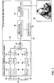
- Fig. 1 is a block diagram that schematically illustrates an ultrasound imaging system 20, in accordance with an embodiment of the present invention.
- System 20 is typically used for producing ultrasound images of a target organ of a patient.
- System 20 comprises an array 24 of ultrasound transducers 28, which are coupled to the patient body during imaging.
- the transducers transmit an ultrasonic signal into the tissue, and receive respective signals that comprise reflections ("echoes") of the transmitted signal from the tissue.
- the received signals are processed, using methods that are described herein, so as to reconstruct and display an ultrasound image 42 of the target organ.
- system 20 comprises a frequency-domain beamforming unit 32, a time-domain reconstruction unit 36 and an image construction unit 40.
- a controller 44 controls the various system components.
- Beamforming unit 32 computes, for each transducer 28, a set of Fourier coefficients of the signal received by that transducer. These coefficients are referred to as transducer-specific Fourier coefficients.
- Unit 32 then combines the transducer-specific Fourier coefficients to produce a set of Fourier coefficients that represent a directional beamformed signal, which is produced from the multiple signals received by transducers 28. In the beamformed signal, the reflections from a selected direction in the tissue relative to array 24 are emphasized.
- the Fourier coefficients of the beamformed signal are referred to as beamforming Fourier coefficients.
- Unit 32 derives the beamforming Fourier coefficients from the transducer-specific Fourier coefficients directly in the frequency domain.
- the beamforming Fourier coefficients are provided as input to time-domain reconstruction unit 36.
- Unit 36 reconstructs the beamformed signal for the selected direction from the beamforming Fourier coefficients.
- Image construction unit 40 constructs a graphical image of the tissue in the scanned sector, e.g., image 42 shown in the figure.
- the resulting image is provided as output, e.g., displayed to an operator and/or recorded.
- beamforming unit 32 comprises multiple processing chains, a respective processing chain per each transducer 28.
- Each processing chain comprises a filter 48, a sampler 52, a Fast Fourier Transform (FFT) module 56 and a weighting module 60.
- the outputs of the processing chains are summed by an adder 64, and the sum is normalized by a gain module 68.
- the configuration of the processing chains in unit 32 is an example configuration. In alternative embodiments, the processing chains may use other elements or configurations for computing the Fourier coefficients of the received signals.
- the output of module 68 comprises the beamforming Fourier coefficients, i.e., the Fourier coefficients of the beamformed signal. The operation of unit 32 is described in detail below.
- the system configuration of Fig. 1 is an example configuration, which is chosen purely for the sake of conceptual clarity. In alternative embodiments, any other suitable system configuration can be used.
- the elements of system 20 may be implemented using hardware. Digital elements can be implemented, for example, in one or more off-the-shelf devices, Application-Specific Integrated Circuits (ASICs) or FPGAs. Analog elements can be implemented, for example, using discrete components and/or one or more analog ICs. Some system elements may be implemented, additionally or alternatively, using software running on a suitable processor, e.g., a Digital Signal Processor (DSP). Some system elements may be implemented using a combination of hardware and software elements.
- DSP Digital Signal Processor
- system 20 may be implemented using a general-purpose computer, which is programmed in software to carry out the functions described herein.
- the software may be downloaded to the processor in electronic form, over a network, for example, or it may, alternatively or additionally, be provided and/or stored on non-transitory tangible media, such as magnetic, optical, or electronic memory.
- processing circuitry that carries out the disclosed techniques.
- processing circuitry typically operates in conjunction with a front end or other input interface that receives the signals from the ultrasound transducers.
- the front end (or input interface) is not shown in Fig. 1 for the sake of clarity, but is shown in Fig. 4 below.
- frequency-domain coefficients refers mainly to Fourier coefficients.
- the disclosed techniques can be carried out using coefficients of any suitable frequency-domain transform or signal representation, such as, for example, Fourier coefficients, Fast Fourier Transform (FFT) coefficients and Discrete Fourier Transform (DFT) coefficients.
- FFT Fast Fourier Transform
- DFT Discrete Fourier Transform
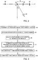
- Fig. 2 is a diagram showing the geometry of array 24 of ultrasound transducers 28, in accordance with an embodiment of the present invention.
- the number of transducers in the array is denoted M
- the transducers are assumed to lie in a linear array along the x axis with a reference element denoted m 0 at the origin.
- the model assumed herein is planar, with the perpendicular axis to the x axis denoted z .
- the distance between the m th transducer and the origin is denoted ⁇ m .
- This array geometry is given purely by way of example.
- the disclosed techniques can be used with any other suitable array geometry, including, for example, two-dimensional transducer arrays used for three-dimensional imaging.
- the signal is reflected from a point reflector 50 located at a certain distance from the array at direction ⁇ .
- Reflector 50 scatters the signal, and the scattered echoes are eventually received by the M transducers 28 at times that depend on their distances from the reflector.
- ⁇ m ( t ; ⁇ ) denote the signal received by the m th transducer
- ⁇ m ( t ; ⁇ ) denote the time of reception of the echo at the m th transducer.
- the beamforming operation involves applying appropriate time delays to the signals received by the different transducers, such that the echoes become time-aligned, and averaging the delayed signals.
- the time delays depend on the geometry of the array, on the direction ⁇ , and on the distance to reflector 50 along direction ⁇ .
- the beamformed signal is both directed toward direction ⁇ , and focused on the specific distance of reflector 50 from the array.
- This kind of beamforming (sometimes referred to as “dynamic focusing") provides high Signal-to-Noise Ratio (SNR) and fine angular resolution, but on the other hand incurs heavy computational load and high sampling rate.
- SNR Signal-to-Noise Ratio
- the beamforming scheme described above is typical of ultrasound applications, and is chosen purely by way of example. In alternative embodiments, the disclosed techniques can be used with any other suitable beamforming scheme.
- system 20 performs the beamforming operation in the frequency domain rather than in the time domain.
- sampling rate requirements and processing rates can be relaxed considerably.
- the disclosed techniques perform frequency-domain beamforming without making any assumptions (e.g., sparsity) on the properties of the received signals. When such information regarding the signal properties is available, beamforming in frequency can be used to further reduce the rate.
- the following description shows the relation between the Fourier coefficients of the individual signals received by the various transducers (denoted transducer-specific Fourier coefficients) and the Fourier coefficients of the beamformed signal (denoted beamforming Fourier coefficients).
- the description that follows refers to the specific beamforming scheme of Equations [1] and [2].
- the disclosed techniques are applicable in a similar manner to other forms of beamforming.
- the support of the beamformed signal ⁇ ( t ; ⁇ ) is the finite time interval [0, T B ( ⁇ )), wherein T B ( ⁇ ) ⁇ T , with T denoting the penetration depth of the tissue in question.
- , ⁇ m T ; ⁇ t 1 + ⁇ m 2 cos ⁇ 2 t ⁇ ⁇ m sin ⁇ 2 ⁇ exp i 2 ⁇ T k ⁇ m ⁇ tsin ⁇ t ⁇ ⁇ m sin ⁇ ⁇ m ⁇ ⁇ m / c
- c k , m s can be well approximated by replacing the infinite sum in Equation [9] with a finite sum: c k , m s ⁇ ⁇ n ⁇ v k ⁇ m s k ⁇ n Q k , m , ⁇ n
- B denote the set of transducer-specific Fourier coefficients corresponding to the actual signal bandwidth, i.e., the values of k for which ⁇ m s k is non-zero or at least larger than a threshold. It follows that the bandwidth ⁇ BF of the beamformed signal contains no more than B + N 1 + N 2 non-zero frequency components.
- Equations [5] and [11] above define the relationship between the beamforming Fourier coefficients (the Fourier series coefficients of the beamformed signal) and the transducer-specific Fourier coefficients (the Fourier series coefficients of the individual signals received by transducers 28).
- c k N ⁇ c k s , 0 ⁇ k ⁇ P c k ⁇ N s , N ⁇ P ⁇ k ⁇ N 0, otherwise
- Equations [13] and [14] thus define the relationship between the DFT coefficients of the beamformed signal and the DFT coefficients of the received signals.
- the above relationship refers to one particular beamforming scheme, which is chosen by way of example.
- the disclosed techniques are applicable in a similar manner to other forms of beamforming.
- Fig. 3 is a flow chart that schematically illustrates a method for ultrasound imaging, performed by system 20 of Fig. 1 above, in accordance with an embodiment of the present invention.
- the method begins with system 20 transmitting an ultrasound signal into the tissue in question, at a transmission step 60.
- Transducers 28 receive the reflected echoes, at a reception step 64.
- Unit 32 computes the transducer-specific Fourier coefficients, at a transducer-specific calculation step 68.
- filter 48 filters the received signal ⁇ m ( t ) with a suitable kernel s *(- t ). (Filtering with a kernel is one possible example implementation. In alternative embodiments, other suitable analog means can be used, or the signal can first be sampled and then its rate reduced digitally.)
- Sampler 52 digitizes the filtered signal at a low sampling rate, which is defined by the effective bandwidth of the transmitted signal, typically corresponding to the Nyquist rate with respect to the effective bandwidth of the transmitted signal. (Sampling at the Nyquist rate is typically used when no signal structure is assumed. When exploiting the signal structure, as will be explained below, only a portion of the signal bandwidth is needed and the sampling rate can be reduced below the Nyquist rate.)
- FFT module 56 computes the DFT coefficients of the digitized signal, to produce ⁇ m [ n ].
- Weighting module 60 applies weighting with the appropriate elements of ⁇ Q k , m , ⁇ [ n ] ⁇ . This process is performed in a similar manner in all M processing chains. Alternatively, unit 32 may use any other suitable process to obtain the Fourier coefficients of the signal over the desired bandwidth. The processing and/or sampling rate are affected by this bandwidth only.
- IDFT time-domain reconstruction unit 36
- steps 60-76 is typically repeated over multiple values of ⁇ , e.g., by scanning a desired angular sector relative to array 24.
- image construction unit 40 constructs and outputs an image of the target organ from the time-domain beamformed signals obtained for the different values of ⁇ .
- Performing the beamforming operation in the frequency domain enables system 20 to sample the signals received by transducers 28 with a low sampling rate, while still providing high imaging quality.
- the bandwidth ⁇ BF of the beamformed signal contains approximately B non-zero frequency components, wherein B denotes the effective bandwidth of the received signals.
- unit 32 exploits this property and calculates, for each received signal, the DFT coefficients only for the B non-zero frequency components in ⁇ BF .
- the ratio between the cardinality of the set ⁇ and the overall number of samples N needed by the conventional beamforming rate f s depends on the oversampling factor.
- the beamforming rate f s is often defined as four to ten times the pass-band bandwidth of the received signals, meaning B / N is on the order of 0.1-0.25. Assuming it is possible to obtain the set ⁇ using B low-rate samples of each received signal, this ratio implies a potential four- to ten-fold reduction in sampling rate relative to time-domain beamforming.
- unit 32 samples the received signals using such a low sampling rate so as to obtain the appropriate non-zero Fourier coefficients.
- Example sub-Nyquist sampling schemes that can be used for this purpose are described, for example, in the paper “Innovation Rate Sampling of Pulse Streams with Application to Ultrasound Imaging” by Tur et al., in the paper “Compressed Beamforming in Ultrasound Imaging” by Wagner et al., as well as in U.S. Patent Application Publications 2011/0225218 and 2013/0038479 , which are both assigned to the assignee of the present patent application.
- each received signal is filtered by the respective filter 48 with a kernel s* ( -t ) .
- the kernel is defined based on the pulse shape of the transmitted ultrasound signal and the set ⁇ .
- Reconstruction unit 36 then applies IDFT to the output of unit 32, so as to reconstruct the time-domain beamformed signal.
- unit 36 pads the elements of ⁇ BF with zeros prior to performing IDFT, in order to improve time resolution.
- unit 36 pads the elements of ⁇ BF with N - B zeros. Alternatively, however, any other suitable padding ratio can be used.
- the above technique reduces the amount of noise in the sampled signal, since conventional time-domain sampling captures noise in the entire frequency spectrum up to the signal frequency and not only within the actual signal bandwidth. Moreover, the above technique reduces processing rates. The effect of this technique on imaging quality is demonstrated in U.S. Provisional Patent Application 61/733,913 , cited above.
- unit 32 of system 20 achieves an additional reduction in sampling rate by computing only a partial subset of the non-zero DFT coefficients of the received signals.
- the subset is denoted ⁇ , ⁇ ⁇ ⁇ BF ,
- unit 32 computes only M + N 1 + N 2 frequency components for each received signal, i.e., only M + N 1 + N 2 samples per processing channel.
- unit 36 reconstructs the beamformed signal using Compressed Sensing (CS) techniques or sparse recovery methods.
- CS-based reconstruction can typically be used when the signal structure is exploited.
- FPI Finite Rate of Innovation
- the beamformed signal can be modeled as a sum of replicas of the known transmitted pulse h ( t ) with unknown amplitudes and delays. See, for example, the article by Wagner at al., cited above.
- the recovery operation is thus equivalent to determining vector b from vector c.
- reconstruction unit 36 of system 20 determines b by solving the optimization problem: mi n b ⁇ b ⁇ 1 s u b j e c t t o ⁇ Ab ⁇ c ⁇ 2 ⁇ ⁇ wherein ⁇ 1 denotes I1 norm (sum of absolute values) and ⁇ 2 denotes I2 norm (Root Mean Square - RMS).
- Equation [20] assumes that the received signals comprise a relatively small number of strong reflectors, plus multiple additional scattered echoes that are typically two orders of magnitude weaker.
- vector b is compressible, i.e., approximately but not entirely sparse.
- This signal model is highly descriptive of ultrasound reflections from tissue, which comprise strong reflections plus a considerable amount of speckle. This property of b is well captured by the 11 norm in Equation [20].
- the I1-norm optimization of Equation [20] is one example of a recovery scheme that assumes that the signal is compressible, but not necessarily sparse. In alternative embodiments, any other recovery method that operates under a constraint that the signal is compressible can be used.
- unit 36 may use various techniques for recovery of sinusoids from a sum-of-sinusoids.
- Example methods include MUSIC, ESPRIT, Capon beamforming, among others. Any such technique can be used by unit 36 to solve Equation [18], and do not require sparsity assumptions. Instead, these techniques exploit the structure in the signal.
- unit 36 may solve the optimization problem of Equation [20] in any suitable way.
- Example optimization schemes that can be used for this purpose are second-order methods such as interior-point methods described by Candes and Romberg, in “11-magic: Recovery of Sparse Signals via Convex Programming,” October, 2005; and by Grant and Boyd, in “The CVX User's Guide,” CVX Research, Inc., November, 2013.
- unit 36 Other example optimization schemes that can be used by unit 36 are first-order methods based on iterative shrinkage, as described by Beck and Teboulle, in “A Fast Iterative Shrinkage-Thresholding Algorithm for Linear Inverse Problems," SIAM Journal on Imaging Sciences, volume 2, number 1, 2009, pages 183-202 ; and by Hale et al., in “A Fixed-Point Continuation Method for 11-Regularized Minimization with Application to Compressed Sensing," CAAM Technical Report TR07-07, Rice University, July 7, 2007 .
- Fig. 4 is a block diagram that schematically illustrates an ultrasound imaging system 90, in accordance with an alternative embodiment of the present invention.
- System 90 comprises an array 94 of ultrasound transducers that are used both for beamformed transmission and for beamformed reception.
- the figure shows a single transmission path and a single reception path.
- the system comprises a respective transmission path and a respective reception path per transducer.
- a transmit beamformer 98 On transmission, a transmit beamformer 98 generates a beamformed set of digital signals for transmission.
- a set of Digital to Analog Converters (DACs) 102 convert the digital signals into analog ultrasound signals.
- a set of amplifiers 106 amplify the ultrasound signals, and the signals are fed via respective Transmit/Receive (T/R) switches 110 to array 94.
- T/R Transmit/Receive
- the received ultrasound signals from the transducers pass through T/R switches 110 and are amplifiers by respective amplifiers 114.
- a set of Low-Pass Filters (LPFs) 118 filter the received signals, and the filtered signals are sampled (digitized) using respective Analog to Digital Converters (ADCs) 122.
- LPFs Low-Pass Filters
- the digital circuitry of system 90 comprises high-speed logic that processes the digitized received signal.
- the high-speed logic comprises a Quadrature down-converter 130 followed by a pair of LPFs 134.
- the complex (I/Q) baseband signal produced by the down-converter is provided to a DFT module 138, which computes DFT coefficients of the received signal.
- a frequency-domain receive beamformer 142 recovers the beamformed signal from the DFT coefficients of the multiple received signals, using the frequency-domain beamforming methods described herein.
- elements 110, 114, 118, 122, 130 and 134 serve as an input interface that receives the ultrasound reflections
- elements 138 and 142 serve as processing circuitry that computes the transducer-specific frequency-domain coefficients for each of the received signals, derives the frequency-domain coefficients of the beamformed signal from the transducer-specific frequency-domain coefficients, and reconstructs the ultrasound image of the target organ based on the beamforming frequency-domain coefficients.
Landscapes
- Engineering & Computer Science (AREA)
- Physics & Mathematics (AREA)
- General Physics & Mathematics (AREA)
- Life Sciences & Earth Sciences (AREA)
- Health & Medical Sciences (AREA)
- Computer Networks & Wireless Communication (AREA)
- Radar, Positioning & Navigation (AREA)
- Remote Sensing (AREA)
- Acoustics & Sound (AREA)
- Multimedia (AREA)
- Nuclear Medicine, Radiotherapy & Molecular Imaging (AREA)
- Medical Informatics (AREA)
- Computer Vision & Pattern Recognition (AREA)
- Pathology (AREA)
- Radiology & Medical Imaging (AREA)
- Biomedical Technology (AREA)
- Heart & Thoracic Surgery (AREA)
- Biophysics (AREA)
- Molecular Biology (AREA)
- Surgery (AREA)
- Animal Behavior & Ethology (AREA)
- General Health & Medical Sciences (AREA)
- Public Health (AREA)
- Veterinary Medicine (AREA)
- Ultra Sonic Daignosis Equipment (AREA)
- Measurement Of Velocity Or Position Using Acoustic Or Ultrasonic Waves (AREA)
Claims (6)
- Verfahren für die medizinische Ultraschallbildgebung, umfassend:Empfangen jeweiliger Signale von mehreren Umformern, die Reflexionen eines übertragenen Signals von einem Ziel umfassen; undErzeugen eines Bildes des Ziels, durch:Berechnen von Frequenzdomänen-Fourierreihe-Koeffizienten für jedes der von den Umformern empfangenen Signale;Ableiten, von den Frequenzdomänen-Fourierreihe-Koeffizienten, von strahlenbildenden Frequenzdomänenkoeffizienten eines strahlengebildeten Signals, in dem die aus einer ausgewählten Richtung relativ zu den Umformern empfangenen Reflexionen verstärkt sind, wobei die strahlenbildenden Frequenzdomänenkoeffizienten gemäß der folgenden Gleichung definiert sind,
 θ die Richtung der Übertragung eines gebildeten Strahls ist;M die Anzahl der Umformer in der Reihe ist;N die Anzahl an Proben des strahlengebildeten Signals ist;ñ eine Summierungshilfsvariable ist;ϕm[n] DFT-Koeffizienten bezeichnet;Qk,m,θ die Fourier-Koeffizienten einer Verzerrungsfunktion qk,m(t; θ) in Bezug auf [0, T) sind;und N1 und N2 numerisch gewählte Werte zum Erfassen des Großteils der Energie der Fourier-Koeffizienten Q k,m,θ[n] der Verzerrungsfunktion q k,m,(t;θ) sind;und
wobei Qk,m,θ[n] der Fourier-Koeffizient von qk,m,(t;θ) ist, definiert wie folgt: T die Penetrationstiefe repräsentiert;t Zeit repräsentiert;I [...) eine Indikatorfunktion ist, die für a≤t<b gleich eins und ansonsten gleich null ist;γm δm/c ist;und δm der Abstand zwischen dem m-ten Umformer und dem Ursprung ist; undτm (T,θ) definiert ist alsund
 Rekonstruieren des Bildes des Ziels in der ausgewählten Richtung auf Grundlage der strahlenbildenden Frequenzdomänenkoeffizienten;wobei das Ableiten der strahlenbildenden Frequenzdomänenkoeffizienten das Berechnen der strahlenbildenden Frequenzdomänenkoeffizienten nur innerhalb einer effektiven Bandbreite des strahlengebildeten Signals umfasst, während entweder der vollständige Satz der Koeffizienten innerhalb der effektiven Bandbreite oder sein partieller Teilsatz berechnet wird;wobei, wenn der vollständige Satz berechnet wird, das Rekonstruieren des Bildes das Anwenden einer umgekehrten Fourier-Transformation auf die strahlenbildenden Frequenzdomänenkoeffizienten unter Verwendung einer umgekehrten diskreten Fourier-Transformation umfasst, um ein strahlengebildetes Signal zu erhalten;wenn nur ein partieller Teilsatz berechnet wird, gegeben durch einen Vektor
 wobei H eine diagonale M-um-M-Matrix ist, deren k-tes diagonales Element hk ist, wobeihk den DFT-Koeffizienten der übertragenen Pulsprobe h[n] bezeichnet,D eine M-um-N-Matrix ist, gebildet durch die Entnahme des Satzes µ an Reihen aus einer N-um-N-DFT-Matrix, undb ein Vektor der Länge N ist, dessen l-tes Element bl ist,wobei das strahlengebildete Signal wiederhergestellt wird, indem angenommen wird, dass c eine komprimierbare Expansion aufweist.
 - Verfahren nach Anspruch 1, wobei das Rekonstruieren des Bildes das Schätzen des strahlengebildeten Signals in Zeitdomäne auf Grundlage der strahlenbildenden Frequenzdomänenkoeffizienten und das Rekonstruieren des Bildes aus dem geschätzten strahlengebildeten Signal umfasst.
- Verfahren nach Anspruch 1, wobei das Schätzen des strahlengebildeten Signals das Anwenden einer |1-Norm-Optimierung auf die strahlenbildenden Frequenzdomänenkoeffizienten umfasst.
- Verfahren nach einem der vorhergehenden Ansprüche, wobei das Rekonstruieren des Bildes des Ziels das Rekonstruieren sowohl dominanter Reflexionen als auch von Sprenkeln auf Grundlage der strahlenbildenden Frequenzdomänenkoeffizienten umfasst.
- Verfahren nach einem der vorhergehenden Ansprüche, wobei das Berechnen der umformerspezifischen Frequenzdomänenkoeffizienten das Ableiten der umformerspezifischen Frequenzdomänenkoeffizienten von Sub-Nyquist-Proben der empfangenen Signale umfasst.
- Vorrichtung für die Ultraschallbildgebung, umfassend:eine Eingabeschnittstelle, die ausgelegt ist, um jeweiliger Signale von mehreren Umformern, die Reflexionen eines übertragenen Signals von einem Ziel umfassen, zu empfangen; undVerarbeitungsschaltung, die ausgelegt ist, um ein Bild des Ziels unabhängig von Seltenheit der empfangenen Signale zu erzeugen, durch Berechnen von Frequenzdomänen-Fourierreihe-Koeffizienten für jedes der von den Umformern empfangenen Signale, Ableiten, von den Frequenzdomänenkoeffizienten, von strahlenbildenden Frequenzdomänenkoeffizienten eines strahlengebildeten Signals, in dem die aus einer ausgewählten Richtung relativ zu den Umformern empfangenen Reflexionen verstärkt sind, und Rekonstruieren des Bildes des Ziels in der ausgewählten Richtung auf Grundlage der strahlenbildenden Frequenzdomänenkoeffizienten, wobei die Verarbeitungsschaltung angeordnet ist, um das Verfahren nach einem der Ansprüche 1 bis 5 auszuführen.
Applications Claiming Priority (1)
| Application Number | Priority Date | Filing Date | Title |
|---|---|---|---|
| US201261733913P | 2012-12-06 | 2012-12-06 |
Publications (2)
| Publication Number | Publication Date |
|---|---|
| EP2741103A1 EP2741103A1 (de) | 2014-06-11 |
| EP2741103B1 true EP2741103B1 (de) | 2018-04-11 |
Family
ID=49726551
Family Applications (1)
| Application Number | Title | Priority Date | Filing Date |
|---|---|---|---|
| EP13195572.6A Not-in-force EP2741103B1 (de) | 2012-12-06 | 2013-12-03 | Strahlformung im Frequenzbereich |
Country Status (3)
| Country | Link |
|---|---|
| US (1) | US9778557B2 (de) |
| EP (1) | EP2741103B1 (de) |
| CN (1) | CN103852748B (de) |
Families Citing this family (11)
| Publication number | Priority date | Publication date | Assignee | Title |
|---|---|---|---|---|
| GB2533388B (en) | 2014-12-17 | 2021-01-06 | Sezanne Marine Ltd | Aspects of a sonar system |
| US10271821B2 (en) | 2014-12-23 | 2019-04-30 | Industrial Technology Research Institute | Method of ultrasound imaging and ultrasound scanner |
| CA2973899A1 (en) | 2015-01-23 | 2016-07-28 | Dalhousie University | Systems and methods for beamforming using variable sampling |
| CN104734791B (zh) * | 2015-04-22 | 2017-04-12 | 哈尔滨工业大学 | 基于fri的稀疏多频带信号频谱定位方法 |
| US10305584B2 (en) * | 2015-10-20 | 2019-05-28 | Samsung Electronics Co., Ltd. | Apparatus and method for performing beamforming operation in communication system supporting frequency division-multiple input multiple output scheme |
| CN105515695B (zh) * | 2015-12-04 | 2017-12-19 | 哈尔滨工程大学 | 基于调制宽带转换器的压缩采样信号检测方法 |
| WO2018083522A1 (en) * | 2016-11-03 | 2018-05-11 | Nokia Technologies Oy | Beamforming |
| US20190331794A1 (en) * | 2017-01-02 | 2019-10-31 | Technion Research & Development Foundation Ltd. | Beamforming with coded signals in frequency domain |
| CN110501429B (zh) * | 2019-07-24 | 2022-05-20 | 江苏大学 | 一种阵列超声信号稀疏采样方法 |
| US20220026570A1 (en) * | 2019-11-07 | 2022-01-27 | Coda Octopus Group Inc. | Techniques for sonar data processing |
| CN111830477B (zh) * | 2020-06-16 | 2022-09-06 | 哈尔滨工业大学 | 一种基于fri采样的时延多普勒参数联合估计方法 |
Family Cites Families (7)
| Publication number | Priority date | Publication date | Assignee | Title |
|---|---|---|---|---|
| US4112430A (en) * | 1977-06-01 | 1978-09-05 | The United States Of America As Represented By The Secretary Of The Navy | Beamformer for wideband signals |
| GB2329072A (en) * | 1997-09-09 | 1999-03-10 | Secr Defence | Processing of signals incident on an array |
| US6278890B1 (en) * | 1998-11-09 | 2001-08-21 | Medacoustics, Inc. | Non-invasive turbulent blood flow imaging system |
| US8428378B2 (en) * | 2010-03-11 | 2013-04-23 | Texas Instruments Incorporated | Post-beamformer ultrasound compression |
| EP2367293B1 (de) | 2010-03-14 | 2014-12-24 | Technion Research & Development Foundation | Abtastung eines Impulsstroms mit niedriger Rate |
| WO2011135472A2 (en) | 2010-04-27 | 2011-11-03 | Technion Research & Development Foundation Ltd. | Multi-channel sampling of pulse streams at the rate of innovation |
| US8582865B2 (en) * | 2010-04-28 | 2013-11-12 | General Electric Company | Ultrasound imaging with ray casting and software-based image reconstruction |
-
2013
- 2013-12-03 EP EP13195572.6A patent/EP2741103B1/de not_active Not-in-force
- 2013-12-05 US US14/097,281 patent/US9778557B2/en not_active Expired - Fee Related
- 2013-12-06 CN CN201310657146.9A patent/CN103852748B/zh not_active Expired - Fee Related
Non-Patent Citations (1)
| Title |
|---|
| None * |
Also Published As
| Publication number | Publication date |
|---|---|
| US20140160883A1 (en) | 2014-06-12 |
| CN103852748B (zh) | 2017-09-26 |
| EP2741103A1 (de) | 2014-06-11 |
| US9778557B2 (en) | 2017-10-03 |
| CN103852748A (zh) | 2014-06-11 |
Similar Documents
| Publication | Publication Date | Title |
|---|---|---|
| EP2741103B1 (de) | Strahlformung im Frequenzbereich | |
| US20230000472A1 (en) | Ultrasonic imaging compression methods and apparatus | |
| US9538987B2 (en) | System and method for ultrasound imaging | |
| Wagner et al. | Compressed beamforming in ultrasound imaging | |
| Lingvall et al. | Synthetic aperture imaging using sources with finite aperture: Deconvolution of the spatial impulse response | |
| US8761477B2 (en) | Systems and method for adaptive beamforming for image reconstruction and/or target/source localization | |
| US11846608B2 (en) | Image reconstruction method based on a trained non-linear mapping | |
| Bottenus | Recovery of the complete data set from focused transmit beams | |
| EP3232937B1 (de) | Ultraschallsystem für hochgeschwindigkeits- und hochauflösende bildgebungsanwendungen | |
| US20230270417A1 (en) | Ultrasound beamformer-based channel data compression | |
| JP5865050B2 (ja) | 被検体情報取得装置 | |
| US9465101B2 (en) | Aberration correction with broad transmit beams in medical ultrasound | |
| JP2018512985A (ja) | インパルス応答推定及び遡及的取得による符号化励起イメージングのための方法及びシステム | |
| US20170367684A1 (en) | Systems and methods for super-resolution compact ultrasound imaging | |
| Chernyakova et al. | Fourier-domain beamforming and structure-based reconstruction for plane-wave imaging | |
| US20190331794A1 (en) | Beamforming with coded signals in frequency domain | |
| Mamistvalov et al. | Deep unfolded recovery of sub-nyquist sampled ultrasound images | |
| Krishnan et al. | Efficient parallel adaptive aberration correction | |
| Mamistvalov et al. | Compressed Fourier-domain convolutional beamforming for sub-Nyquist ultrasound imaging | |
| Kirchhof et al. | Frequency subsampling of ultrasound nondestructive measurements: acquisition, reconstruction, and performance | |
| CN111213066A (zh) | 基于模型的图像重建方法 | |
| Polichetti et al. | A computationally efficient nonlinear beamformer based on p-th root signal compression for enhanced ultrasound b-mode imaging | |
| Mamistvalov et al. | Compressed Fourier-domain convolutional beamforming for wireless ultrasound imaging | |
| Mo | A retrospective look at retrospective transmit beamforming | |
| Foroozan et al. | Wave atom based Compressive Sensing and adaptive beamforming in ultrasound imaging |
Legal Events
| Date | Code | Title | Description |
|---|---|---|---|
| PUAI | Public reference made under article 153(3) epc to a published international application that has entered the european phase |
Free format text: ORIGINAL CODE: 0009012 |
|
| 17P | Request for examination filed |
Effective date: 20131203 |
|
| AK | Designated contracting states |
Kind code of ref document: A1 Designated state(s): AL AT BE BG CH CY CZ DE DK EE ES FI FR GB GR HR HU IE IS IT LI LT LU LV MC MK MT NL NO PL PT RO RS SE SI SK SM TR |
|
| AX | Request for extension of the european patent |
Extension state: BA ME |
|
| 17Q | First examination report despatched |
Effective date: 20161010 |
|
| GRAP | Despatch of communication of intention to grant a patent |
Free format text: ORIGINAL CODE: EPIDOSNIGR1 |
|
| INTG | Intention to grant announced |
Effective date: 20171115 |
|
| GRAS | Grant fee paid |
Free format text: ORIGINAL CODE: EPIDOSNIGR3 |
|
| GRAA | (expected) grant |
Free format text: ORIGINAL CODE: 0009210 |
|
| AK | Designated contracting states |
Kind code of ref document: B1 Designated state(s): AL AT BE BG CH CY CZ DE DK EE ES FI FR GB GR HR HU IE IS IT LI LT LU LV MC MK MT NL NO PL PT RO RS SE SI SK SM TR |
|
| REG | Reference to a national code |
Ref country code: GB Ref legal event code: FG4D |
|
| REG | Reference to a national code |
Ref country code: CH Ref legal event code: EP |
|
| REG | Reference to a national code |
Ref country code: AT Ref legal event code: REF Ref document number: 988625 Country of ref document: AT Kind code of ref document: T Effective date: 20180415 |
|
| REG | Reference to a national code |
Ref country code: IE Ref legal event code: FG4D |
|
| REG | Reference to a national code |
Ref country code: DE Ref legal event code: R096 Ref document number: 602013035658 Country of ref document: DE |
|
| REG | Reference to a national code |
Ref country code: NL Ref legal event code: MP Effective date: 20180411 |
|
| REG | Reference to a national code |
Ref country code: LT Ref legal event code: MG4D |
|
| PG25 | Lapsed in a contracting state [announced via postgrant information from national office to epo] |
Ref country code: NL Free format text: LAPSE BECAUSE OF FAILURE TO SUBMIT A TRANSLATION OF THE DESCRIPTION OR TO PAY THE FEE WITHIN THE PRESCRIBED TIME-LIMIT Effective date: 20180411 |
|
| PG25 | Lapsed in a contracting state [announced via postgrant information from national office to epo] |
Ref country code: ES Free format text: LAPSE BECAUSE OF FAILURE TO SUBMIT A TRANSLATION OF THE DESCRIPTION OR TO PAY THE FEE WITHIN THE PRESCRIBED TIME-LIMIT Effective date: 20180411 Ref country code: SE Free format text: LAPSE BECAUSE OF FAILURE TO SUBMIT A TRANSLATION OF THE DESCRIPTION OR TO PAY THE FEE WITHIN THE PRESCRIBED TIME-LIMIT Effective date: 20180411 Ref country code: AL Free format text: LAPSE BECAUSE OF FAILURE TO SUBMIT A TRANSLATION OF THE DESCRIPTION OR TO PAY THE FEE WITHIN THE PRESCRIBED TIME-LIMIT Effective date: 20180411 Ref country code: FI Free format text: LAPSE BECAUSE OF FAILURE TO SUBMIT A TRANSLATION OF THE DESCRIPTION OR TO PAY THE FEE WITHIN THE PRESCRIBED TIME-LIMIT Effective date: 20180411 Ref country code: BG Free format text: LAPSE BECAUSE OF FAILURE TO SUBMIT A TRANSLATION OF THE DESCRIPTION OR TO PAY THE FEE WITHIN THE PRESCRIBED TIME-LIMIT Effective date: 20180711 Ref country code: NO Free format text: LAPSE BECAUSE OF FAILURE TO SUBMIT A TRANSLATION OF THE DESCRIPTION OR TO PAY THE FEE WITHIN THE PRESCRIBED TIME-LIMIT Effective date: 20180711 Ref country code: LT Free format text: LAPSE BECAUSE OF FAILURE TO SUBMIT A TRANSLATION OF THE DESCRIPTION OR TO PAY THE FEE WITHIN THE PRESCRIBED TIME-LIMIT Effective date: 20180411 Ref country code: PL Free format text: LAPSE BECAUSE OF FAILURE TO SUBMIT A TRANSLATION OF THE DESCRIPTION OR TO PAY THE FEE WITHIN THE PRESCRIBED TIME-LIMIT Effective date: 20180411 |
|
| PG25 | Lapsed in a contracting state [announced via postgrant information from national office to epo] |
Ref country code: HR Free format text: LAPSE BECAUSE OF FAILURE TO SUBMIT A TRANSLATION OF THE DESCRIPTION OR TO PAY THE FEE WITHIN THE PRESCRIBED TIME-LIMIT Effective date: 20180411 Ref country code: GR Free format text: LAPSE BECAUSE OF FAILURE TO SUBMIT A TRANSLATION OF THE DESCRIPTION OR TO PAY THE FEE WITHIN THE PRESCRIBED TIME-LIMIT Effective date: 20180712 Ref country code: LV Free format text: LAPSE BECAUSE OF FAILURE TO SUBMIT A TRANSLATION OF THE DESCRIPTION OR TO PAY THE FEE WITHIN THE PRESCRIBED TIME-LIMIT Effective date: 20180411 Ref country code: RS Free format text: LAPSE BECAUSE OF FAILURE TO SUBMIT A TRANSLATION OF THE DESCRIPTION OR TO PAY THE FEE WITHIN THE PRESCRIBED TIME-LIMIT Effective date: 20180411 |
|
| REG | Reference to a national code |
Ref country code: AT Ref legal event code: MK05 Ref document number: 988625 Country of ref document: AT Kind code of ref document: T Effective date: 20180411 |
|
| PG25 | Lapsed in a contracting state [announced via postgrant information from national office to epo] |
Ref country code: PT Free format text: LAPSE BECAUSE OF FAILURE TO SUBMIT A TRANSLATION OF THE DESCRIPTION OR TO PAY THE FEE WITHIN THE PRESCRIBED TIME-LIMIT Effective date: 20180813 |
|
| REG | Reference to a national code |
Ref country code: DE Ref legal event code: R097 Ref document number: 602013035658 Country of ref document: DE |
|
| PG25 | Lapsed in a contracting state [announced via postgrant information from national office to epo] |
Ref country code: CZ Free format text: LAPSE BECAUSE OF FAILURE TO SUBMIT A TRANSLATION OF THE DESCRIPTION OR TO PAY THE FEE WITHIN THE PRESCRIBED TIME-LIMIT Effective date: 20180411 Ref country code: RO Free format text: LAPSE BECAUSE OF FAILURE TO SUBMIT A TRANSLATION OF THE DESCRIPTION OR TO PAY THE FEE WITHIN THE PRESCRIBED TIME-LIMIT Effective date: 20180411 Ref country code: EE Free format text: LAPSE BECAUSE OF FAILURE TO SUBMIT A TRANSLATION OF THE DESCRIPTION OR TO PAY THE FEE WITHIN THE PRESCRIBED TIME-LIMIT Effective date: 20180411 Ref country code: AT Free format text: LAPSE BECAUSE OF FAILURE TO SUBMIT A TRANSLATION OF THE DESCRIPTION OR TO PAY THE FEE WITHIN THE PRESCRIBED TIME-LIMIT Effective date: 20180411 Ref country code: SK Free format text: LAPSE BECAUSE OF FAILURE TO SUBMIT A TRANSLATION OF THE DESCRIPTION OR TO PAY THE FEE WITHIN THE PRESCRIBED TIME-LIMIT Effective date: 20180411 Ref country code: DK Free format text: LAPSE BECAUSE OF FAILURE TO SUBMIT A TRANSLATION OF THE DESCRIPTION OR TO PAY THE FEE WITHIN THE PRESCRIBED TIME-LIMIT Effective date: 20180411 |
|
| PLBE | No opposition filed within time limit |
Free format text: ORIGINAL CODE: 0009261 |
|
| STAA | Information on the status of an ep patent application or granted ep patent |
Free format text: STATUS: NO OPPOSITION FILED WITHIN TIME LIMIT |
|
| PG25 | Lapsed in a contracting state [announced via postgrant information from national office to epo] |
Ref country code: IT Free format text: LAPSE BECAUSE OF FAILURE TO SUBMIT A TRANSLATION OF THE DESCRIPTION OR TO PAY THE FEE WITHIN THE PRESCRIBED TIME-LIMIT Effective date: 20180411 Ref country code: SM Free format text: LAPSE BECAUSE OF FAILURE TO SUBMIT A TRANSLATION OF THE DESCRIPTION OR TO PAY THE FEE WITHIN THE PRESCRIBED TIME-LIMIT Effective date: 20180411 |
|
| 26N | No opposition filed |
Effective date: 20190114 |
|
| PGFP | Annual fee paid to national office [announced via postgrant information from national office to epo] |
Ref country code: DE Payment date: 20190123 Year of fee payment: 6 Ref country code: GB Payment date: 20190121 Year of fee payment: 6 Ref country code: FR Payment date: 20190124 Year of fee payment: 6 |
|
| PG25 | Lapsed in a contracting state [announced via postgrant information from national office to epo] |
Ref country code: SI Free format text: LAPSE BECAUSE OF FAILURE TO SUBMIT A TRANSLATION OF THE DESCRIPTION OR TO PAY THE FEE WITHIN THE PRESCRIBED TIME-LIMIT Effective date: 20180411 |
|
| REG | Reference to a national code |
Ref country code: CH Ref legal event code: PL |
|
| PG25 | Lapsed in a contracting state [announced via postgrant information from national office to epo] |
Ref country code: MC Free format text: LAPSE BECAUSE OF FAILURE TO SUBMIT A TRANSLATION OF THE DESCRIPTION OR TO PAY THE FEE WITHIN THE PRESCRIBED TIME-LIMIT Effective date: 20180411 Ref country code: LU Free format text: LAPSE BECAUSE OF NON-PAYMENT OF DUE FEES Effective date: 20181203 |
|
| REG | Reference to a national code |
Ref country code: IE Ref legal event code: MM4A |
|
| REG | Reference to a national code |
Ref country code: BE Ref legal event code: MM Effective date: 20181231 |
|
| PG25 | Lapsed in a contracting state [announced via postgrant information from national office to epo] |
Ref country code: IE Free format text: LAPSE BECAUSE OF NON-PAYMENT OF DUE FEES Effective date: 20181203 |
|
| PG25 | Lapsed in a contracting state [announced via postgrant information from national office to epo] |
Ref country code: BE Free format text: LAPSE BECAUSE OF NON-PAYMENT OF DUE FEES Effective date: 20181231 |
|
| PG25 | Lapsed in a contracting state [announced via postgrant information from national office to epo] |
Ref country code: CH Free format text: LAPSE BECAUSE OF NON-PAYMENT OF DUE FEES Effective date: 20181231 Ref country code: LI Free format text: LAPSE BECAUSE OF NON-PAYMENT OF DUE FEES Effective date: 20181231 |
|
| PG25 | Lapsed in a contracting state [announced via postgrant information from national office to epo] |
Ref country code: MT Free format text: LAPSE BECAUSE OF NON-PAYMENT OF DUE FEES Effective date: 20181203 |
|
| PG25 | Lapsed in a contracting state [announced via postgrant information from national office to epo] |
Ref country code: TR Free format text: LAPSE BECAUSE OF FAILURE TO SUBMIT A TRANSLATION OF THE DESCRIPTION OR TO PAY THE FEE WITHIN THE PRESCRIBED TIME-LIMIT Effective date: 20180411 |
|
| PG25 | Lapsed in a contracting state [announced via postgrant information from national office to epo] |
Ref country code: HU Free format text: LAPSE BECAUSE OF FAILURE TO SUBMIT A TRANSLATION OF THE DESCRIPTION OR TO PAY THE FEE WITHIN THE PRESCRIBED TIME-LIMIT; INVALID AB INITIO Effective date: 20131203 Ref country code: MK Free format text: LAPSE BECAUSE OF NON-PAYMENT OF DUE FEES Effective date: 20180411 Ref country code: CY Free format text: LAPSE BECAUSE OF FAILURE TO SUBMIT A TRANSLATION OF THE DESCRIPTION OR TO PAY THE FEE WITHIN THE PRESCRIBED TIME-LIMIT Effective date: 20180411 |
|
| REG | Reference to a national code |
Ref country code: DE Ref legal event code: R119 Ref document number: 602013035658 Country of ref document: DE |
|
| PG25 | Lapsed in a contracting state [announced via postgrant information from national office to epo] |
Ref country code: IS Free format text: LAPSE BECAUSE OF FAILURE TO SUBMIT A TRANSLATION OF THE DESCRIPTION OR TO PAY THE FEE WITHIN THE PRESCRIBED TIME-LIMIT Effective date: 20180811 |
|
| GBPC | Gb: european patent ceased through non-payment of renewal fee |
Effective date: 20191203 |
|
| PG25 | Lapsed in a contracting state [announced via postgrant information from national office to epo] |
Ref country code: DE Free format text: LAPSE BECAUSE OF NON-PAYMENT OF DUE FEES Effective date: 20200701 Ref country code: FR Free format text: LAPSE BECAUSE OF NON-PAYMENT OF DUE FEES Effective date: 20191231 Ref country code: GB Free format text: LAPSE BECAUSE OF NON-PAYMENT OF DUE FEES Effective date: 20191203 |