EP3234528B1 - Messgerät zur erfassung wenigstens eines parameters eines fluids - Google Patents
Messgerät zur erfassung wenigstens eines parameters eines fluids Download PDFInfo
- Publication number
- EP3234528B1 EP3234528B1 EP16775663.4A EP16775663A EP3234528B1 EP 3234528 B1 EP3234528 B1 EP 3234528B1 EP 16775663 A EP16775663 A EP 16775663A EP 3234528 B1 EP3234528 B1 EP 3234528B1
- Authority
- EP
- European Patent Office
- Prior art keywords
- measuring device
- sensor
- sensor cap
- electronic component
- housing
- Prior art date
- Legal status (The legal status is an assumption and is not a legal conclusion. Google has not performed a legal analysis and makes no representation as to the accuracy of the status listed.)
- Active
Links
Images


Classifications
-
- G—PHYSICS
- G01—MEASURING; TESTING
- G01K—MEASURING TEMPERATURE; MEASURING QUANTITY OF HEAT; THERMALLY-SENSITIVE ELEMENTS NOT OTHERWISE PROVIDED FOR
- G01K1/00—Details of thermometers not specially adapted for particular types of thermometer
- G01K1/16—Special arrangements for conducting heat from the object to the sensitive element
- G01K1/18—Special arrangements for conducting heat from the object to the sensitive element for reducing thermal inertia
-
- G—PHYSICS
- G01—MEASURING; TESTING
- G01F—MEASURING VOLUME, VOLUME FLOW, MASS FLOW OR LIQUID LEVEL; METERING BY VOLUME
- G01F1/00—Measuring the volume flow or mass flow of fluid or fluent solid material wherein the fluid passes through a meter in a continuous flow
- G01F1/68—Measuring the volume flow or mass flow of fluid or fluent solid material wherein the fluid passes through a meter in a continuous flow by using thermal effects
-
- G—PHYSICS
- G01—MEASURING; TESTING
- G01K—MEASURING TEMPERATURE; MEASURING QUANTITY OF HEAT; THERMALLY-SENSITIVE ELEMENTS NOT OTHERWISE PROVIDED FOR
- G01K13/00—Thermometers specially adapted for specific purposes
- G01K13/02—Thermometers specially adapted for specific purposes for measuring temperature of moving fluids or granular materials capable of flow
-
- G—PHYSICS
- G01—MEASURING; TESTING
- G01F—MEASURING VOLUME, VOLUME FLOW, MASS FLOW OR LIQUID LEVEL; METERING BY VOLUME
- G01F1/00—Measuring the volume flow or mass flow of fluid or fluent solid material wherein the fluid passes through a meter in a continuous flow
- G01F1/68—Measuring the volume flow or mass flow of fluid or fluent solid material wherein the fluid passes through a meter in a continuous flow by using thermal effects
- G01F1/684—Structural arrangements; Mounting of elements, e.g. in relation to fluid flow
- G01F1/688—Structural arrangements; Mounting of elements, e.g. in relation to fluid flow using a particular type of heating, cooling or sensing element
- G01F1/69—Structural arrangements; Mounting of elements, e.g. in relation to fluid flow using a particular type of heating, cooling or sensing element of resistive type
Definitions
- the invention relates to a measuring device for detecting at least one parameter of a fluid, in particular a temperature measuring device and / or a thermal flow sensor for measuring the flow velocity of the fluid.
- Thermal flow sensors work according to the calorimetric measuring principle, in particular according to the hot-wire method.
- a sensor area is heated, which is cooled by the flowing medium.
- the power to be supplied to the sensor region in order to keep the sensor region at a predetermined temperature is a measure of the flow velocity depending on the temperature of the medium.
- a flow sensor which has a wall which comprises at least one cylindrical portion which merges into a hemispherical-shaped end, wherein inside the housing, a heating element and a temperature sensor with the wall of the cylindrical portion are in heat radiation transmitting contact.
- the DE 196 40 772 A1 discloses a measuring sensor for detecting the flow velocity of liquids and gases, which has a housing in contact with the fluid, which comprises a cylindrical portion which merges into a hemispherical-shaped end. Inside the housing are electrical measuring elements with the wall in heat radiation transmitting contact.
- the EP 2 037 247 A2 discloses a temperature sensor with an air gap that isolates the end of the sensor from the rest of the housing.
- DE 10 2009 046653 A1 describes a magnetic-inductive flow measuring system with heatable resistance thermometer.
- a temperature sensor for measuring housing and tool temperatures having a cylindrical, thermally insulating housing, in which a cap made of a thermally conductive material is used.
- the invention has for its object to provide a measuring device for detecting at least one parameter of a fluid, which is characterized by a fast and reliable data acquisition.
- a portion of the hemispherical-shaped end is formed as a sensor cap and consists of a thermally conductive material, while the remaining portion of the hemispherically-shaped end is formed by a thermally insulating material, wherein the electronic component is in contact with the sensor cap.
- the hemispherical-shaped end, the arrangement of the electronic component in the sensor cap and the use of different materials allow a very fast, yet mechanically stable and robust meter.
- the arrangement of the electronic component in the hemispherical end ensures a directional dependence in the arrangement of the measuring device.
- the sensor cap is formed as a spherical segment with a height which is in the range of 0.1 to 0.8 times, preferably in the range of 0.2 to 0.6 times the radius of the hemispherically shaped end.
- the sensor cap is on the one hand large enough to contact the electronic component and on the other hand small enough to a to ensure sufficient stability of the hemispherically shaped end even when the sensor cap is designed for a good heat transfer with a small wall thickness of, for example, 0.5 mm.
- the mass of the thermally conductive material is reduced to a barely needed for mechanical stability minimum, thereby increasing the speed of the response.
- thermally conductive material of the sensor cap a thermal conductivity of at least 300 W / mK and for the thermally insulating material a thermal conductivity of less than 1 W / mK is preferred.
- copper, silver or aluminum and for the section consisting of thermally insulating material, in particular plastic, glass or ceramic, are considered as materials for the sensor cap. Due to the very good thermal conductivity of the coming into contact with the fluid sensor cap a very good heat transfer between the fluid and the sensor and thus a very fast response is possible.
- the sensor cap may have a wall thickness which is smaller than the wall thickness of the thermally insulating material portion, wherein the wall thickness of the thermally insulating material portion of the hemispherically-shaped end, for example, 0.8 mm.
- the cylindrical portion is also made of a thermally insulating material, in particular of plastic, glass or ceramic, at least at the area adjoining the hemispherical end.
- the mass of the adjacent cylindrical portion is reduced by the adaptation of the wall thickness to a barely needed for mechanical stability minimum (diameter of the cylindrical portion, for example 9 mm, wall thickness in the region of the hemispherical end, for example, 0.5 - 0.8 mm).
- the wall thickness of the cylindrical portion can with increasing distance from increase from hemispherical end (in particular from about 0.5 - 0.8 mm at the hemispherical end to about 1 - 1.3 mm at the end of the cylindrical portion).
- the cylindrical portion and the hemispherical-shaped end in the transition region between the cylindrical portion and the hemispherical-shaped end have the same outer diameter and the smoothest possible transition on the outside is present.
- the transition on the outside between the sensor cap and the remaining portion of the hemispherical-shaped end should also be made as smooth as possible.
- the housing is also preferably rotationally symmetrical, so that in particular the sensor cap is aligned rotationally symmetrical to the longitudinal axis of the measuring device. In this way, any turbulence in a flowing fluid can be avoided. Also, no or little pollution can accumulate in the transition areas.
- the electronic component can in particular be a temperature sensor and / or a heating element (for example a temperature-dependent resistor).
- the attachment of the electronic component is preferably carried out in that it is arranged on an inserted into the housing circuit board, wherein the electronic component is soldered to the sensor cap.
- the electronic component can be soldered, for example, with a first solder on the circuit board, while the electronic component is soldered to the sensor cap with a second solder.
- the first solder has a melting point which is at least 50 ° C. higher than the second lot on.
- the second solder is formed by a Lotformteil with predetermined mass, which is placed on the sensor cap before inserting the circuit board at this or inside the housing.
- the heating of the sensor cap must be carried out at a temperature which is higher than the melting point of the solder preform, but less than the melting point of the first solder.
- the measuring device is designed as a temperature measuring device.
- the electronic component is formed by a temperature sensor (for example, a PT500, NTC, PTC, etc.).
- a temperature sensor for example, a PT500, NTC, PTC, etc.
- the heat transfer resistance of the fluid through the highly thermally conductive sensor cap on the very good thermal conductivity compound (solder) to the temperature sensor is so low that it detects a change in temperature in the fluid very quickly.
- the heat transfer resistance between the sensor cap and the remaining portion of the hemispherical end and the adjoining cylindrical portion is significantly higher, so that the housing reacts much slower to temperature changes of the fluid. Due to the choice of a very good thermal conductivity material for the sensor cap and manufacturing tolerance tolerances in the attachment of the flow sensor can be compensated by rotation of the sensor with flowing fluid.
- the measuring device is designed as a flow sensor, wherein the electronic component in contact with the sensor cap is formed by a heating element for the purpose of heating the sensor cap.
- the heating element is preferably designed as a heating and temperature sensor element (for example as a temperature-dependent resistor), which on the one hand transfer heat to the sensor cap and on the other hand, the temperature of the sensor cap can be determined.
- the cylindrical section of the housing of the flow sensor has a temperature sensor section consisting of a thermally conductive material (in particular a thermal conductivity of at least 300 W / mK), which is in operative connection with at least one temperature sensor arranged in the interior of the temperature sensor section.
- a temperature sensor section consisting of a thermally conductive material (in particular a thermal conductivity of at least 300 W / mK), which is in operative connection with at least one temperature sensor arranged in the interior of the temperature sensor section.
- the flow rate is determined in a known manner by means of a power supplied to the heating element and a temperature of the medium measured by the temperature sensor.
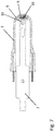
- the measuring device shown is a temperature measuring device 1 for detecting the temperature of a fluid. It has a housing 2 coming into contact with the fluid and having a wall which comprises at least one cylindrical section 3 which is in a hemispherical shape trained end 4 passes.
- a portion of the hemispherical-shaped end 4 as a sensor cap 5 made of a thermally conductive material and the remaining portion 6 of the hemispherical-shaped end of a thermally insulating material is formed.
- the overall tubular housing 2 allows the insertion of a printed circuit board 7.
- 2 guide grooves 8, 9 are provided for the targeted insertion of the printed circuit board 7 in the interior of the housing.
- On the circuit board 7 designed as a temperature sensor electronic component 10 is arranged, which is soldered in the installed state with the sensor cap 5, so that the electronic component with the sensor cap 5 is in heat radiation transmitting contact.
- the sensor cap 5 is formed as a spherical segment with a height h, wherein the height h in the range of 0.1 to 0.8 times the radius r of the hemispherical-shaped end, preferably in the range of 0.2 to 0.6 times Radius is ( Fig. 2 ).
- the thermally conductive material of the sensor cap 5 preferably has a thermal conductivity of at least 300 W / mK and the thermally insulating material of the remaining portion 6 has a thermal conductivity of less than 1 W / mK.
- a material for the sensor cap is in particular copper, silver or aluminum and as a thermally insulating material preferably plastic, glass or ceramic into consideration.
- the cylindrical portion 3 is also formed at least at the adjoining the hemispherical end 4 region also made of a thermally insulating material, in particular of plastic, glass or ceramic.
- the cylindrical portion 3 and the remaining portion 6 of the hemispherically shaped end 4 are integrally formed, in particular as a plastic injection molded part.
- the transitions between the cylindrical portion 3 and the thermally insulating material consisting of remaining portion 6 of the hemispherical-shaped end 4 and the sensor cap 5 are formed smooth at least on the outside.
- the sensor cap 5 has, for example, a relatively small wall thickness of 0.5 mm, for example, for a good heat transfer, while the wall thickness of the remaining section 6 of the hemispherical end is 0.8 mm, for example.
- the mass of the adjacent cylindrical portion 3 is reduced by adapting the wall thickness to a minimum needed for mechanical stability.
- the wall thickness of the cylindrical portion 3 can increase with increasing distance from the hemispherical end 4 of, for example, 0.8 to 1.2 mm.
- the diameter of the cylindrical portion 3 and the hemispherical-shaped end for example, 9 mm.
- the housing 2 is rotationally symmetrical about a longitudinal axis 11.
- That in the 4 to 6 shown second embodiment of a measuring device according to the invention represents a flow sensor 12.
- the outer shape of the housing of the flow sensor 12 is formed substantially identical; In particular, in the region of the cylindrical portion 3 and the hemispherically shaped end 4 with the sensor cap 5 and the remaining portion 6. At the cylindrical portion 3, however, closes at the area remote from the hemispherically shaped end remote from an existing thermally conductive material temperature sensing portion 13 before a further thermally insulating housing section 14 follows.
- the temperature sensor portion 13 is thus arranged approximately annularly between the cylindrical portion 3 and the thermally insulating housing portion 14.
- the electronic component 10 which is in heat-transferring contact with the sensor cap is formed in this embodiment by a heating element, which can preferably be used both for heating the sensor cap 5 and for measuring the temperature of the sensor cap 5.
- a heating element which can preferably be used both for heating the sensor cap 5 and for measuring the temperature of the sensor cap 5.
- a temperature-dependent resistor which can act as a temperature sensor or heating element depending on the control is suitable.
- the existing of a thermally conductive material temperature sensor section 13 is operatively connected to at least one temperature sensor 15 disposed in the interior of the housing, which is also arranged on the circuit board 7 and is connected via a solder connection to the temperature sensing section 13. Furthermore, an evaluation unit (not shown) for determining the flow velocity is provided on the basis of a power supplied to the heating element (electronic component 10) and a temperature of the medium measured by the temperature sensor 15. In this case, the sensor cap 5 is heated by the heating element to a predetermined temperature. The achievement or maintenance of the predetermined temperature of the sensor cap 5 is monitored by another with the sensor cap 5 related temperature sensor or skillful manner by the electronic component 10 itself.
- the electronic component must be able to act both as a heating element and as a temperature sensor.
- the flow rate can then be determined on the basis of the heating power supplied via the electronic component 10 and the temperature of the fluid measured by the temperature sensor 15 in the temperature sensor section. This type of determination of the flow rate is well known and will therefore not be explained in detail.
- Fig. 7 Based on Fig. 7 will be explained below how the contact between the electronic component 10 and the sensor cap 5 is achieved.
- the electronic component (before inserting the circuit board 7 in the housing) is soldered to a first solder on the circuit board.
- a Lotformteil 16 is placed inside the housing to the sensor cap 5, to then insert the circuit board 7 in the housing until the soldered on the circuit board 7 electronic component 10 comes into contact with the Lotformteil 16.
- the contacting of the electronic component 10 with the sensor cap 5 is effected by heating the sensor cap from the outside until the solder preform melts. So that the electronic component 10 does not come loose from the printed circuit board, the first solder, with which the electronic component 10 is fastened on the printed circuit board 7, should have a melting point at least 50 ° C.
- the Sensor cap 5 is heated for contacting with the electronic component only to a temperature which is higher than the melting point of the second solder but less than the melting point of the first solder. With this method, a reproducible contacting of the electronic component 10 with the sensor cap 5 can be achieved. In the same way, the temperature sensor 15 can be contacted with the temperature sensing portion 13 of the housing from the outside.
Landscapes
- Physics & Mathematics (AREA)
- General Physics & Mathematics (AREA)
- Fluid Mechanics (AREA)
- Measuring Temperature Or Quantity Of Heat (AREA)
Description
- Die Erfindung betrifft ein Messgerät zur Erfassung wenigstens eines Parameters eines Fluids, insbesondere eine Temperaturmesseinrichtung und/oder einen thermischen Strömungssensor zur Messung der Strömungsgeschwindigkeit des Fluids.
- Thermische Strömungssensoren arbeiten nach dem kalorimetrischen Messprinzip, insbesondere nach der Hitzdrahtmethode. Hierbei wird ein Sensorbereich aufgeheizt, der durch das vorbeiströmende Medium gekühlt wird. Die dem Sensorbereich zuzuführende Leistung, um den Sensorbereich auf einer vorgegebenen Temperatur zu halten, stellt dabei in Abhängigkeit der Temperatur des Mediums ein Maß für die Strömungsgeschwindigkeit dar.
- Aus der
US 7,178,410 B2 ist ein Strömungssensor bekannt, der eine Wandung aufweist, die zumindest einen zylindrischen Abschnitt umfasst, der in ein halbkugelförmig ausgebildetes Ende übergeht, wobei im Inneren des Gehäuses ein Heizelement und ein Temperatursensor mit der Wandung des zylindrischen Abschnitts in Wärmestrahlung übertragenden Kontakt stehen. - Die
DE 196 40 772 A1 offenbart ein Messsensor zur Erfassung der Strömungsgeschwindigkeit von Flüssigkeiten und Gasen, der ein mit dem Fluid in Kontakt kommendes Gehäuse aufweist, das einen zylindrischen Abschnitt umfasst, der in ein halbkugelförmig ausgebildetes Ende übergeht. Im Inneren des Gehäuses stehen elektrische Messelemente mit der Wandung in Wärmestrahlung übertragenden Kontakt. - Die
EP 2 037 247 A2 offenbart einen Temperatursensor mit einem Luftspalt, der das Ende des Sensors vom Rest des Gehäuses isoliert. In derDE 10 2009 046653 A1 wird ein magnetisch-induktives Durchflussmesssystem mit beheizbarem Widerstandsthermometer beschreiben. Aus derDE 79 09 350 U1 ist ferner ein Temperaturfühler zum Messen von Gehäuse- und Werkzeugtemperaturen bekannt, der ein zylindrisches, thermisch isolierendes Gehäuse aufweist, in das eine Kappe aus einem wärmeleitfähigen Material eingesetzt ist. - Der Erfindung liegt die Aufgabe zugrunde, ein Messgerät zur Erfassung wenigstens eines Parameters eines Fluids anzugeben, das sich durch eine schnelle und zuverlässige Messwerterfassung auszeichnet.
- Erfindungsgemäß wird diese Aufgabe durch die Merkmale des Anspruches 1 gelöst.
- Das erfindungsgemäße Messgerät zur Erfassung wenigstens eines Parameters eines Fluids sieht ein mit dem Fluid in Kontakt kommendes Gehäuse vor, das eine Wandung aufweist, die zumindest einen zylindrischen Abschnitt umfasst, der in ein halbkugelförmig ausgebildetes Ende übergeht, und wobei im Inneren des Gehäuses wenigstens ein elektronisches Bauteil mit der Wandung in Wärmestrahlung übertragenden Kontakt steht. Ein Abschnitt des halbkugelförmig ausgebildeten Endes ist als Sensorkappe ausgebildet und besteht dabei aus einem wärmeleitfähigen Material, während der verbleibende Abschnitt des halbkugelförmig ausgebildeten Endes durch ein thermisch isolierendes Material gebildet wird, wobei das elektronische Bauteil mit der Sensorkappe in Kontakt steht.
- Das halbkugelförmig ausgebildete Ende, die Anordnung des elektronischen Bauteils in der Sensorkappe und die Verwendung unterschiedlicher Materialien ermöglichen ein sehr schnelles, aber dennoch mechanisch stabiles und robustes Messgerät. Die Anordnung des elektronischen Bauteils im halbkugelförmig ausgebildeten Ende gewährleistet eine Richtungsabhängigkeit bei der Anordnung des Messgeräts.
- Weitere Ausgestaltungen der Erfindung sind Gegenstand der Unteransprüche.
- Gemäß einem bevorzugten Ausführungsbeispiel ist die Sensorkappe als Kugelsegment mit einer Höhe ausgebildet, die im Bereich des 0,1- bis 0,8-fachen, vorzugsweise im Bereich des 0,2- bis 0,6-fachen Radius des halbkugelförmig ausgebildete Endes liegt. Dadurch ist die Sensorkappe einerseits groß genug, um das elektronische Bauteil zu kontaktieren und anderseits klein genug, um eine ausreichende Stabilität des halbkugelförmig ausgebildeten Endes auch dann zu gewährleisten, wenn die Sensorkappe für einen guten Wärmeübergang mit einer geringen Wandstärke von beispielsweise 0,5 mm ausgebildet ist. Dadurch wird die Masse des wärmeleitfähigen Materials auf ein gerade noch für die mechanische Stabilität benötigtes Minimum reduziert, um dadurch die Geschwindigkeit des Ansprechverhaltens zu steigern.
- Für das wärmeleitende Material der Sensorkappe wird eine Wärmeleitfähigkeit von wenigstens 300 W/mK und für das thermisch isolierende Material eine Wärmeleitfähigkeit von kleiner 1 W/mK bevorzugt. Als Materialien für die Sensorkappe kommen insbesondere Kupfer, Silber oder Aluminium und für den aus thermisch isolierendem Material bestehenden Abschnitt insbesondere Kunststoff, Glas oder Keramik in Betracht. Durch die sehr gute Wärmeleitfähigkeit der mit dem Fluid in Kontakt kommenden Sensorkappe wird ein sehr guter Wärmeübertragung zwischen Fluid und Sensor und dadurch ein sehr schnelles Ansprechverhalten ermöglicht.
- Um eine ausreichende mechanische Stabilität zu gewährleisten, kann die Sensorkappe eine Wandstärke aufweisen, die kleiner als die Wandstärke des aus thermisch isolierendem Material bestehenden Abschnitts ist, wobei die Wandstärke des aus thermisch isolierendem Material bestehenden Abschnitts des halbkugelförmig ausgebildeten Endes beispielsweise 0,8 mm beträgt.
- Gemäß einer weiteren Ausgestaltung der Erfindung ist der zylindrische Abschnitt zumindest an dem sich an das halbkugelförmig ausgebildete Ende anschließenden Bereich ebenfalls aus einem thermisch isolierendem Material, insbesondere aus Kunststoff, Glas oder Keramik, ausgebildet. Die Masse des angrenzenden zylindrischen Abschnitts wird durch die Anpassung der Wandstärke auf ein gerade noch für die mechanische Stabilität benötigtes Minimum reduziert (Durchmesser des zylindrischen Abschnitts beispielsweise 9 mm, Wandstärke im Bereich des halbkugelförmigen Endes beispielsweise 0,5 - 0,8 mm). Die Wandstärke des zylindrischen Abschnitts kann dabei mit zunehmendem Abstand vom halbkugelförmigen Ende ansteigen (insbesondere von ca. 0,5 - 0,8 mm am halbkugelförmigen Ende bis auf ca. 1 - 1,3 mm am Ende des zylindrischen Abschnitts). Dadurch wird die Wärmeleitung aus dem Messbereich in das Gehäuse trotz hoher mechanischer Festigkeit zusätzlich minimiert.
- Des Weiteren ist es von Vorteil, wenn der zylindrische Abschnitt und das halbkugelförmig ausgebildete Ende im Übergangsbereich zwischen dem zylindrischen Abschnitt und dem halbkugelförmig ausgebildeten Ende den gleichen Außendurchmesser aufweisen und ein möglichst glatter Übergang auf der Außenseite vorhanden ist. Auch der Übergang an der Außenseite zwischen der Sensorkappe und dem verbleibenden Abschnitt des halbkugelförmig ausgebildeten Endes sollte ebenfalls möglichst glatt ausgeführt werden. Das Gehäuse wird darüber hinaus vorzugsweise rotationssymmetrisch ausgebildet, sodass insbesondere auch die Sensorkappe rotationssymmetrisch zur Längsachse des Messgerätes ausgerichtet ist. Auf diese Weise werden etwaige Turbulenzen bei einem strömendem Fluid vermieden. Auch kann sich in den Übergangsbereichen keine bzw. nur wenig Verschmutzung anlagern.
- Bedingt durch die Kugelgeometrie und der Verwendung unterschiedlicher Materialien kann trotz geringer Wandstärken ein sehr schneller, aber dennoch mechanisch stabiler und robuster Sensor gebildet werden.
- Bei dem elektronischen Bauteil kann es sich insbesondere um einen Temperatursensor und/oder ein Heizelement (beispielsweise einen temperaturabhängigen Widerstand) handeln. Die Anbringung des elektronischen Bauteils erfolgt vorzugsweise dadurch, dass es auf einer in das Gehäuse eingeschobenen Leiterplatte angeordnet ist, wobei das elektronische Bauteil mit der Sensorkappe verlötet wird. Dazu kann das elektronische Bauteil beispielsweise mit einem ersten Lot auf der Leiterplatte verlötet sein, während das elektronische Bauteil mit der Sensorkappe mit einem zweiten Lot verlötet wird. Um beim Verlöten des Bauteils mit der Sensorkappe ein Lösen des Bauteils von der Leiterplatte zu verhindern, weist das erste Lot einen um wenigstens 50°C höheren Schmelzpunkt als das zweite Lot auf. Die technische Realisierung kann dadurch erfolgen, dass das zweite Lot durch ein Lotformteil mit vorgegebener Masse gebildet wird, das vor dem Einschieben der Leiterplatte an dieser oder im Inneren des Gehäuses an der Sensorkappe platziert wird. Durch Erhitzten der Sensorkappe von außen schmilzt das Lotformteil, sodass es zu einer Kontaktierung des elektronischen Bauteils mit der Sensorkappe kommt. Das Erhitzen der Sensorkappe muss dabei mit einer Temperatur erfolgen, die höher als der Schmelzpunkt des Lötformteils, aber geringer als der Schmelzpunkt des ersten Lots ist.
- Gemäß einem ersten Ausführungsbeispiel ist das Messgerät als Temperaturmesseinrichtung ausgebildet. Hierzu wird das elektronische Bauteil durch einen Temperatursensor (beispielsweise ein PT500, NTC, PTC etc.) gebildet. Der Wärmeübergangswiderstand vom Fluid durch die sehr gut wärmeleitfähige Sensorkappe über die sehr gut wärmeleitfähige Verbindung (Lot) zum Temperatursensor (beispielsweise ein temperaturabhängiger Widerstand) ist dabei so gering, dass dieser eine Temperaturänderung im Fluid sehr schnell erfasst. Der Wärmeübergangswiderstand zwischen der Sensorkappe und dem verbleibenden Abschnitt des halbkugelförmig ausgebildeten Endes und dem sich daran anschließenden zylindrischen Abschnitt ist dabei deutlich höher, so dass das Gehäuse deutlich langsamer auf Temperaturänderungen des Fluids reagiert. Bedingt durch die Wahl eines sehr gut wärmeleitfähigen Materials für die Sensorkappe können auch fertigungsbedingte Toleranzabweichungen in der Anbringung des Strömungssensors durch Verdrehung des Sensors bei strömendem Fluid ausgeglichen werden.
- Gemäß einem zweiten Ausführungsbeispiel ist das Messgerät als Strömungssensor ausgebildet, wobei das mit der Sensorkappe in Kontakt stehende elektronische Bauteil durch ein Heizelement zum Zwecke des Aufheizens des Sensorkappe ausgebildet ist. Das Heizelement wird vorzugsweise als Heiz- und Temperaturfühlerelement (beispielsweise als temperaturabhängiger Widerstand) ausgebildet, wodurch einerseits Wärme an die Sensorkappe übertragen und andererseits die Temperatur der Sensorkappe ermittelt werden kann.
- Gemäß einer weiteren Ausgestaltung weist der zylindrische Abschnitt des Gehäuses des Strömungssensors einen aus einem wärmeleitfähigen Material (insbesondere eine Wärmeleitfähigkeit von wenigstens 300 W/mK) bestehenden Temperaturfühlerabschnitt auf, der mit wenigstens einem im Inneren des Temperaturfühlerabschnitts angeordneten Temperatursensors in Wirkverbindung steht. Über eine Auswertungseinheit wird in bekannter Art und Weise die Strömungsgeschwindigkeit anhand einer dem Heizelement zugeführten Leistung und einer vom Temperatursensor gemessenen Temperatur des Mediums ermittelt.
- Weitere Ausgestaltungen der Erfindung werden im Folgenden anhand der nachfolgenden Beschreibung und der Zeichnung näher erläutert.
- In der Zeichnung zeigen
- Fig. 1
- eine dreidimensionale Darstellung einer erfindungsgemäßen Temperaturmesseinrichtung,
- Fig. 2
- eine Längsschnittdarstellung der Temperaturmesseinrichtung gemäß
Fig.1 , - Fig. 3
- eine Schnittdarstellung längs der Linie A - A der
Fig. 2 , - Fig. 4
- eine dreidimensionale Darstellung eines erfindungsgemäßen Strömungssensors,
- Fig. 5
- eine Längsschnittdarstellung des Strömungssensors gemäß
Fig.4 , - Fig. 6
- eine Schnittdarstellung längs der Linie B - B der
Fig. 5 und - Fig.7
- eine Längsschnittdarstellung des Messgeräts mit Lotformteil während des Zusammenbaus.
- Bei dem in
Fig. 1 dargestellten Messgerät handelt es sich um eine Temperaturmesseinrichtung 1 zur Erfassung der Temperatur eines Fluids. Sie weist ein mit dem Fluid in Kontakt kommendes Gehäuse 2 mit einer Wandung auf, die zumindest einen zylindrischen Abschnitt 3 umfasst, der in ein halbkugelförmig ausgebildetes Ende 4 übergeht. Dabei ist ein Abschnitt des halbkugelförmig ausgebildeten Endes 4 als Sensorkappe 5 aus einem wärmeleitfähigen Material und der verbleibende Abschnitt 6 des halbkugelförmig ausgebildeten Endes aus einem thermisch isolierenden Material ausgebildet. - Das insgesamt rohrförmig ausgebildete Gehäuse 2 ermöglicht das Einschieben einer Leiterplatte 7. Dazu können im Inneren des Gehäuses 2 Führungsnuten 8, 9 zum gezielten Einführen der Leiterplatte 7 vorgesehen werden. Auf der Leiterplatte 7 ist ein als Temperatursensor ausgebildetes elektronisches Bauteil 10 angeordnet, das im eingebauten Zustand mit der Sensorkappe 5 verlötet ist, sodass das elektronische Bauteil mit der Sensorkappe 5 in Wärmestrahlung übertragenden Kontakt steht.
- Die Sensorkappe 5 ist als Kugelsegment mit einer Höhe h ausgebildet, wobei die Höhe h im Bereich des 0,1- bis 0,8-fachen Radius r des halbkugelförmig ausgebildeten Endes, vorzugsweise im Bereich des 0,2- bis 0,6-fachen Radius liegt (
Fig. 2 ). - Das wärmeleitende Material der Sensorkappe 5 weist vorzugsweise eine Wärmeleitfähigkeit von wenigstens 300 W/mK und das thermisch isolierende Material des verbleibenden Abschnitt 6 eine Wärmeleitfähigkeit von kleiner 1 W/mK auf. Als Material für die Sensorkappe kommt insbesondere Kupfer, Silber oder Aluminium und als thermisch isolierendes Material vorzugsweise Kunststoff, Glas oder Keramik in Betracht. Der zylindrische Abschnitt 3 ist zumindest an den sich an das halbkugelförmig ausgebildete Ende 4 anschließenden Bereich ebenfalls aus einem thermisch isolierenden Material, insbesondere aus Kunststoff, Glas oder Keramik, ausgebildet. Zweckmäßigerweise werden der zylindrische Abschnitt 3 und der verbleibende Abschnitt 6 des halbkugelförmig ausgebildeten Endes 4 einstückig, insbesondere als Kunststoffspritzgussteil, ausgebildet.
- Wie sich aus
Fig. 2 unmittelbar ergibt, sind die Übergänge zwischen dem zylindrischen Abschnitt 3 und dem aus thermisch isolierenden Material bestehenden, verbleibenden Abschnitt 6 des halbkugelförmigen ausgebildeten Endes 4 und der Sensorkappe 5 zumindest auf der Außenseite glatt ausgebildet. Die Sensorkappe 5 weist für einen guten Wärmeübergang beispielsweise eine relativ geringe Wandstärke von beispielsweise 0,5 mm auf, während die Wandstärke des verbleibenden Abschnitts 6 des halbkugelförmig ausgebildeten Endes beispielsweise 0,8 mm beträgt. Die Masse des angrenzenden zylindrischen Abschnitts 3 wird durch die Anpassung der Wandstärke auf ein gerade noch für die mechanische Stabilität benötigtes Minimum reduziert. Die Wandstärke des zylindrischen Abschnitts 3 kann dabei mit zunehmendem Abstand vom halbkugelförmigen Ende 4 von beispielsweise 0,8 auf 1,2 mm ansteigen. Der Durchmesser des zylindrischen Abschnitts 3 bzw. des halbkugelförmig ausgebildeten Ende beträgt beispielsweise 9 mm. Insgesamt ist das Gehäuse 2 rotationssymmetrisch um eine Längsachse 11 ausgebildet. - Das in den
Fig. 4 bis 6 gezeigte zweite Ausführungsbeispiel eines erfindungsgemäßen Messgeräts stellt einen Strömungssensor 12 dar. Die äußere Form des Gehäuses des Strömungssensors 12 ist im Wesentlichen identisch ausgebildet; insbesondere im Bereich des zylindrischen Abschnitts 3 und dem halbkugelförmig ausgebildeten Ende 4 mit der Sensorkappe 5 und dem verbleibenden Abschnitt 6. An den zylindrischen Abschnitt 3 schließt sich allerdings am vom halbkugelförmig ausgebildeten Ende abgewandten Bereich ein aus einem wärmeleitfähigen Material bestehender Temperaturfühlerabschnitt 13 an, bevor ein weiterer thermisch isolierender Gehäuseabschnitt 14 folgt. Der Temperaturfühlerabschnitt 13 ist somit in etwa ringförmig zwischen dem zylindrischen Abschnitt 3 und dem thermisch isolierenden Gehäuseabschnitt 14 angeordnet. - Das mit der Sensorkappe in wärmeübertragenden Kontakt stehende elektronische Bauteil 10 wird bei diesem Ausführungsbeispiel durch ein Heizelement gebildet, das vorzugsweise sowohl zum Aufheizen der Sensorkappe 5 als auch zum Messen der Temperatur der Sensorkappe 5 verwendet werden kann. Hierfür eignet sich beispielsweise ein temperaturabhängiger Widerstand, der je nach Ansteuerung wahlweise als Temperatursensor oder Heizelement fungieren kann.
- Der aus einem wärmeleitfähigen Material bestehende Temperaturfühlerabschnitt 13 steht mit wenigstens einem im Inneren des Gehäuses angeordneten Temperatursensor 15 in Wirkverbindung, welcher ebenfalls auf der Leiterplatte 7 angeordnet ist und über eine Lötverbindung mit dem Temperaturfühlerabschnitt 13 verbunden ist. Des Weiteren ist eine nicht näher dargestellte Auswertungseinheit zur Ermittlung der Strömungsgeschwindigkeit anhand einer dem Heizelement (elektronisches Bauteil 10) zugeführten Leistung und einer vom Temperatursensor 15 gemessenen Temperatur des Mediums vorgesehen. Dabei wird die Sensorkappe 5 über das Heizelement auf eine vorgegebene Temperatur aufgeheizt. Das Erreichen bzw. Halten der vorgegebenen Temperatur der Sensorkappe 5 wird durch einen weiteren mit der Sensorkappe 5 in Verbindung stehenden Temperatursensor oder geschickter Weise durch das elektronische Bauteil 10 selbst überwacht. Dazu muss das elektronische Bauteil sowohl als Heizelement als auch als Temperatursensor wirken können. Die Strömungsgeschwindigkeit kann dann anhand der über das elektronische Bauteil 10 zugeführten Heizleistung und die durch den Temperatursensor 15 im Temperaturfühlerabschnitt gemessene Temperatur des Fluids ermittelt werden. Diese Art der Ermittlung der Strömungsgeschwindigkeit ist allgemein bekannt und wird daher nicht näher erläutert.
- Anhand von
Fig. 7 wird im Folgenden erläutert, wie die Kontaktierung zwischen dem elektronischen Bauteil 10 und der Sensorkappe 5 erreicht wird. Hierzu wird das elektronische Bauteil (vor dem Einführen der Leiterplatte 7 in das Gehäuse) mit einem ersten Lot auf der Leiterplatte verlötet. Dann wird ein Lotformteil 16 im Inneren des Gehäuses an der Sensorkappe 5 platziert, um anschließend die Leiterplatte 7 in das Gehäuse einzuschieben, bis das auf der Leiterplatte 7 angelötete elektronische Bauteil 10 mit dem Lotformteil 16 in Kontakt kommt. Die Kontaktierung des elektronischen Bauteils 10 mit der Sensorkappe 5 erfolgt durch Erwärmen der Sensorkappe von außen, bis das Lotformteil schmilzt. Damit sich das elektronische Bauteil 10 hierbei nicht von der Leiterplatte löst, sollte das ersten Lot, mit dem das elektronische Bauteil 10 auf der Leiterplatte 7 befestigt ist einen um wenigstens 50°C höheren Schmelzpunkt als das zweite Lot aufweisen. Die Sensorkappe 5 wird zur Kontaktierung mit dem elektronischen Bauteil nur auf eine Temperatur aufgeheizt, die höher als der Schmelzpunkt des zweiten Lots aber geringer als der Schmelzpunkt des ersten Lots ist. Mit dieser Methode lässt sich eine reproduzierbare Kontaktierung des elektronischen Bauteils 10 mit der Sensorkappe 5 erreichen. In gleicher Art und Weise kann der Temperatursensor 15 mit dem Temperaturfühlerabschnitt 13 des Gehäuses von außen kontaktiert werden.
Claims (19)
- Messgerät zur Erfassung wenigstens eines Parameters eines Fluids mit einem mit dem Fluid in Kontakt kommenden Gehäuse (2), das eine Wandung aufweist, die zumindest einen zylindrischen Abschnitt (3) umfasst, der in ein halbkugelförmig ausgebildetes Ende (4) übergeht, und wobei im Inneren des Gehäuses wenigstens ein elektronisches Bauteil (10) mit der Wandung in Wärmestrahlung übertragenden Kontakt steht,
dadurch gekennzeichnet, dass ein Abschnitt des halbkugelförmig ausgebildeten Endes (4) als Sensorkappe (5) aus einem wärmeleitfähigen Material und der verbleibende Abschnitt (6) des halbkugelförmig ausgebildeten Endes (4) aus einem thermisch isolierenden Material besteht und das elektronische Bauteil (10) mit der Sensorkappe (5) in Kontakt steht. - Messgerät nach Anspruch 1, dadurch gekennzeichnet, dass das halbkugelförmig ausgebildete Ende (4) einen Radius (r) aufweist und die Sensorkappe (5) als Kugelsegment mit einer Höhe (h) ausgebildet ist, wobei die Höhe im Bereich des 0,1- bis 0,8-fachen Radius, vorzugsweise im Bereich des 0,2- bis 0,6-fachen Radius liegt.
- Messgerät nach Anspruch 1, dadurch gekennzeichnet, dass das wärmeleitende Material der Sensorkappe (5) eine Wärmeleitfähigkeit von wenigstens 300 W/mK und das thermisch isolierende Material eine Wärmeleitfähigkeit von kleiner 1 W/mK aufweisen.
- Messgerät nach Anspruch 1, dadurch gekennzeichnet, dass das die Sensorkappe (5) eine Wandstärke aufweist, die kleiner als die Wandstärke des aus thermisch isolierendem Material bestehenden Abschnitts ist.
- Messgerät nach Anspruch 1, dadurch gekennzeichnet, dass die Sensorkappe (5) aus Kupfer, Silber oder Aluminium und der aus thermisch isolierendem Material bestehende Abschnitt aus Kunststoff, Glas oder Keramik bestehen.
- Messgerät nach Anspruch 1, dadurch gekennzeichnet, dass der zylindrische Abschnitt (3) und das halbkugelförmig ausgebildete Ende (4) im Übergangsbereich zwischen dem zylindrischen Abschnitt und dem halbkugelförmig ausgebildeten Ende den gleichen Außendurchmesser aufweisen.
- Messgerät nach Anspruch 1, dadurch gekennzeichnet, dass der zylindrische Abschnitt 83) zumindest an den sich an das halbkugelförmig ausgebildete Ende (4) anschließenden Bereich ebenfalls aus einem thermisch isolierendem Material, insbesondere aus Kunststoff, Glas oder Keramik, ausgebildet ist.
- Messgerät nach Anspruch 7, dadurch gekennzeichnet, dass der zylindrische, aus dem thermisch isolierenden Material bestehende Abschnitt (3) eine Wandstärke aufweist, die mit zunehmendem Abstand vom halbkugelförmig ausgebildeten Ende (4) ansteigt.
- Messgerät nach Anspruch 1, dadurch gekennzeichnet, dass die Übergänge zwischen dem zylindrischen Abschnitt (3), dem aus thermisch isolierenden Material bestehenden Abschnitt (6) des halbkugelförmigen ausgebildeten Endes und der Sensorkappe (5) glatt ausgebildet sind.
- Messgerät nach Anspruch 1, dadurch gekennzeichnet, dass es sich bei dem elektronischen Bauteil (10) um einen Temperatursensor und/oder ein Heizelement handelt.
- Messgerät nach Anspruch 1, dadurch gekennzeichnet, dass es sich bei dem elektronischen Bauteil (10) um einen temperaturabhängigen Widerstand handelt.
- Messgerät nach Anspruch 1, dadurch gekennzeichnet, dass der zylindrische Abschnitt (3) des Gehäuses einen aus einem wärmeleitfähigen Material bestehenden Temperaturfühlerabschnitt (13) aufweist, der mit wenigstens einem im Inneren des Temperaturfühlerabschnitts angeordneten Temperatursensor (15) in Wirkverbindung steht.
- Messgerät nach Anspruch 12, dadurch gekennzeichnet, dass das Messgerät als Strömungssensor (12) ausgebildet ist und das mit der Sensorkappe (5) in Kontakt stehende elektronische Bauteil (10) durch ein Heizelement zum Zwecke des Aufheizens des Sensorkappe ausgebildet ist.
- Messgerät nach Anspruch 13, dadurch gekennzeichnet, dass eine Auswertungseinheit zur Ermittlung der Strömungsgeschwindigkeit anhand einer dem Heizelement zugeführten Leistung und einer vom Temperatursensor (15) gemessenen Temperatur des Mediums vorgesehen ist.
- Messgerät nach Anspruch 1, dadurch gekennzeichnet, dass das Gehäuse (2) rotationssymmetrisch ausgebildet ist.
- Messgerät nach Anspruch 1, dadurch gekennzeichnet, dass das Messgerät als Temperaturmesseinrichtung (1) ausgebildet ist.
- Messgerät nach Anspruch 1, dadurch gekennzeichnet, dass das elektronische Bauteil (10) auf einer in das Gehäuse eingeschobenen Leiterplatte (7) angeordnet ist und das elektronische Bauteil (10) mit der Sensorkappe (5) verlötet ist.
- Messgerät nach Anspruch 17, dadurch gekennzeichnet, dass das elektronische Bauteil (10) mit einem ersten Lot auf der Leiterplatte (7) verlötet ist und das elektronische Bauteil (10) mit der Sensorkappe (5) mit einem zweiten Lot verlötet ist, wobei das ersten Lot einen um wenigstens 50°C höheren Schmelzpunkt als das zweite Lot aufweist.
- Messgerät nach Anspruch 18, dadurch gekennzeichnet, dass das zweite Lot durch ein Lotformteil (16) mit vorgegebener Masse gebildet wird, das vor dem Einschieben der Leiterplatte (7) im Inneren des Gehäuses (2) an der Sensorkappe (5) platziert ist.
Applications Claiming Priority (2)
| Application Number | Priority Date | Filing Date | Title |
|---|---|---|---|
| DE102015117723 | 2015-10-19 | ||
| PCT/EP2016/073213 WO2017067770A1 (de) | 2015-10-19 | 2016-09-29 | Messgerät zur erfassung wenigstens eines parameters eines fluids |
Publications (2)
| Publication Number | Publication Date |
|---|---|
| EP3234528A1 EP3234528A1 (de) | 2017-10-25 |
| EP3234528B1 true EP3234528B1 (de) | 2019-01-23 |
Family
ID=57068091
Family Applications (1)
| Application Number | Title | Priority Date | Filing Date |
|---|---|---|---|
| EP16775663.4A Active EP3234528B1 (de) | 2015-10-19 | 2016-09-29 | Messgerät zur erfassung wenigstens eines parameters eines fluids |
Country Status (2)
| Country | Link |
|---|---|
| EP (1) | EP3234528B1 (de) |
| WO (1) | WO2017067770A1 (de) |
Family Cites Families (5)
| Publication number | Priority date | Publication date | Assignee | Title |
|---|---|---|---|---|
| DE7909350U1 (de) * | 1979-03-31 | 1979-07-05 | Dynamit Nobel Ag, 5210 Troisdorf | Temperaturfuehler zum messen von gehaeuse- und werkzeugtemperaturen |
| DE19640772A1 (de) * | 1995-10-07 | 1997-04-30 | Hiss Eckart | Meßsensor |
| US7178410B2 (en) | 2004-03-22 | 2007-02-20 | Cleanalert, Llc | Clogging detector for air filter |
| GB0717994D0 (en) * | 2007-09-14 | 2007-10-24 | Epiq Nv | Temperature sensor |
| DE102009046653A1 (de) * | 2009-11-12 | 2011-05-19 | Endress + Hauser Flowtec Ag | Magnetisch-induktives Durchflussmesssystem mit beheizbarem Widerstandsthermometer |
-
2016
- 2016-09-29 WO PCT/EP2016/073213 patent/WO2017067770A1/de not_active Ceased
- 2016-09-29 EP EP16775663.4A patent/EP3234528B1/de active Active
Non-Patent Citations (1)
| Title |
|---|
| None * |
Also Published As
| Publication number | Publication date |
|---|---|
| WO2017067770A1 (de) | 2017-04-27 |
| EP3234528A1 (de) | 2017-10-25 |
Similar Documents
| Publication | Publication Date | Title |
|---|---|---|
| EP3942266B1 (de) | Sensoranordnung mit einem temperatursensorelement und verfahren zu deren herstellung | |
| EP0348660A2 (de) | Positionsmesseinrichtung | |
| DE102013208785B4 (de) | Thermisches Durchflussmessgerät mit einer zylinderförmigen Sensorspitze | |
| EP3237851B1 (de) | Thermisches durchflussmessgerät | |
| EP0471316A1 (de) | Sensor für thermische Massenstrommesser | |
| DE102007005670A1 (de) | Magnetisch induktives Durchflussmessgerät und Verfahren zur Herstellung eines solchen Durchflussmessgerätes | |
| DE4233284C2 (de) | Kalorimetrischer Strömungswächter | |
| EP3791147A1 (de) | Messeinsatz mit schutzrohr | |
| DE3818957C2 (de) | Temperatur-Meßfühleranordnung | |
| DE10051558C2 (de) | Sensoreinheit mit einem Luftfeuchte-Sensor und mit einem Lufttemperatur-Sensor | |
| DE202013103404U1 (de) | Temperatursensor und Thermisches Durchflussmessgerät | |
| EP3234528B1 (de) | Messgerät zur erfassung wenigstens eines parameters eines fluids | |
| EP1384561A1 (de) | Temperaturfühler und Heizvorrichtung für Heisskanalsysteme | |
| DE19901935C2 (de) | Temperaturfühler | |
| EP2215442B1 (de) | Vorrichtung zur bestimmung und/oder überwachung der temperatur | |
| DE19610885B4 (de) | Wärmeübergangsmeßgerät | |
| EP3012596A1 (de) | Messeinrichtung zur Bestimmung der Fließgeschwindigkeit eines Mediums in einem Rohr | |
| DE19640773C2 (de) | Meßfühler | |
| EP1787092A1 (de) | Thermische vorrichtung zur bestimmung und/oder überwachung des massedurchlaufs eines messmediums | |
| WO2014041166A2 (de) | Hochtemperatursensor und verfahren zur herstellung einer schutzkappe für einen hochtemperatursensor | |
| EP3980729B1 (de) | Thermisches durchflussmessgerät | |
| DE102017128953B4 (de) | Messeinheit zur Erfassung dynamischer Parameter und bzw. oder physikalischer Eigenschaften von strömenden Medien, vorzugsweise von strömenden Fluiden | |
| DE19802296A1 (de) | Verfahren und Temperaturfühler zur Messung von Oberflächentemperaturen | |
| WO2008145512A2 (de) | Kontaktierung einer vorrichtung zur bestimmung und/oder überwachung einer prozessgrösse | |
| EP3475667B1 (de) | Sensor für ein thermisches durchflussmessgerät, ein thermisches durchflussmessgerät und ein verfahren zum herstellen eines sensors eines thermischen durchflussmessgeräts |
Legal Events
| Date | Code | Title | Description |
|---|---|---|---|
| STAA | Information on the status of an ep patent application or granted ep patent |
Free format text: STATUS: THE INTERNATIONAL PUBLICATION HAS BEEN MADE |
|
| PUAI | Public reference made under article 153(3) epc to a published international application that has entered the european phase |
Free format text: ORIGINAL CODE: 0009012 |
|
| STAA | Information on the status of an ep patent application or granted ep patent |
Free format text: STATUS: REQUEST FOR EXAMINATION WAS MADE |
|
| 17P | Request for examination filed |
Effective date: 20170719 |
|
| AK | Designated contracting states |
Kind code of ref document: A1 Designated state(s): AL AT BE BG CH CY CZ DE DK EE ES FI FR GB GR HR HU IE IS IT LI LT LU LV MC MK MT NL NO PL PT RO RS SE SI SK SM TR |
|
| AX | Request for extension of the european patent |
Extension state: BA ME |
|
| GRAP | Despatch of communication of intention to grant a patent |
Free format text: ORIGINAL CODE: EPIDOSNIGR1 |
|
| STAA | Information on the status of an ep patent application or granted ep patent |
Free format text: STATUS: GRANT OF PATENT IS INTENDED |
|
| INTG | Intention to grant announced |
Effective date: 20181005 |
|
| GRAS | Grant fee paid |
Free format text: ORIGINAL CODE: EPIDOSNIGR3 |
|
| GRAA | (expected) grant |
Free format text: ORIGINAL CODE: 0009210 |
|
| STAA | Information on the status of an ep patent application or granted ep patent |
Free format text: STATUS: THE PATENT HAS BEEN GRANTED |
|
| DAV | Request for validation of the european patent (deleted) | ||
| DAX | Request for extension of the european patent (deleted) | ||
| AK | Designated contracting states |
Kind code of ref document: B1 Designated state(s): AL AT BE BG CH CY CZ DE DK EE ES FI FR GB GR HR HU IE IS IT LI LT LU LV MC MK MT NL NO PL PT RO RS SE SI SK SM TR |
|
| REG | Reference to a national code |
Ref country code: GB Ref legal event code: FG4D Free format text: NOT ENGLISH |
|
| REG | Reference to a national code |
Ref country code: CH Ref legal event code: EP |
|
| REG | Reference to a national code |
Ref country code: AT Ref legal event code: REF Ref document number: 1091813 Country of ref document: AT Kind code of ref document: T Effective date: 20190215 |
|
| REG | Reference to a national code |
Ref country code: IE Ref legal event code: FG4D Free format text: LANGUAGE OF EP DOCUMENT: GERMAN |
|
| REG | Reference to a national code |
Ref country code: DE Ref legal event code: R096 Ref document number: 502016003240 Country of ref document: DE |
|
| REG | Reference to a national code |
Ref country code: NL Ref legal event code: MP Effective date: 20190123 |
|
| PG25 | Lapsed in a contracting state [announced via postgrant information from national office to epo] |
Ref country code: NL Free format text: LAPSE BECAUSE OF FAILURE TO SUBMIT A TRANSLATION OF THE DESCRIPTION OR TO PAY THE FEE WITHIN THE PRESCRIBED TIME-LIMIT Effective date: 20190123 |
|
| PG25 | Lapsed in a contracting state [announced via postgrant information from national office to epo] |
Ref country code: ES Free format text: LAPSE BECAUSE OF FAILURE TO SUBMIT A TRANSLATION OF THE DESCRIPTION OR TO PAY THE FEE WITHIN THE PRESCRIBED TIME-LIMIT Effective date: 20190123 Ref country code: NO Free format text: LAPSE BECAUSE OF FAILURE TO SUBMIT A TRANSLATION OF THE DESCRIPTION OR TO PAY THE FEE WITHIN THE PRESCRIBED TIME-LIMIT Effective date: 20190423 Ref country code: PT Free format text: LAPSE BECAUSE OF FAILURE TO SUBMIT A TRANSLATION OF THE DESCRIPTION OR TO PAY THE FEE WITHIN THE PRESCRIBED TIME-LIMIT Effective date: 20190523 Ref country code: PL Free format text: LAPSE BECAUSE OF FAILURE TO SUBMIT A TRANSLATION OF THE DESCRIPTION OR TO PAY THE FEE WITHIN THE PRESCRIBED TIME-LIMIT Effective date: 20190123 Ref country code: LT Free format text: LAPSE BECAUSE OF FAILURE TO SUBMIT A TRANSLATION OF THE DESCRIPTION OR TO PAY THE FEE WITHIN THE PRESCRIBED TIME-LIMIT Effective date: 20190123 Ref country code: SE Free format text: LAPSE BECAUSE OF FAILURE TO SUBMIT A TRANSLATION OF THE DESCRIPTION OR TO PAY THE FEE WITHIN THE PRESCRIBED TIME-LIMIT Effective date: 20190123 Ref country code: FI Free format text: LAPSE BECAUSE OF FAILURE TO SUBMIT A TRANSLATION OF THE DESCRIPTION OR TO PAY THE FEE WITHIN THE PRESCRIBED TIME-LIMIT Effective date: 20190123 |
|
| PG25 | Lapsed in a contracting state [announced via postgrant information from national office to epo] |
Ref country code: RS Free format text: LAPSE BECAUSE OF FAILURE TO SUBMIT A TRANSLATION OF THE DESCRIPTION OR TO PAY THE FEE WITHIN THE PRESCRIBED TIME-LIMIT Effective date: 20190123 Ref country code: BG Free format text: LAPSE BECAUSE OF FAILURE TO SUBMIT A TRANSLATION OF THE DESCRIPTION OR TO PAY THE FEE WITHIN THE PRESCRIBED TIME-LIMIT Effective date: 20190423 Ref country code: IS Free format text: LAPSE BECAUSE OF FAILURE TO SUBMIT A TRANSLATION OF THE DESCRIPTION OR TO PAY THE FEE WITHIN THE PRESCRIBED TIME-LIMIT Effective date: 20190523 Ref country code: LV Free format text: LAPSE BECAUSE OF FAILURE TO SUBMIT A TRANSLATION OF THE DESCRIPTION OR TO PAY THE FEE WITHIN THE PRESCRIBED TIME-LIMIT Effective date: 20190123 Ref country code: GR Free format text: LAPSE BECAUSE OF FAILURE TO SUBMIT A TRANSLATION OF THE DESCRIPTION OR TO PAY THE FEE WITHIN THE PRESCRIBED TIME-LIMIT Effective date: 20190424 Ref country code: HR Free format text: LAPSE BECAUSE OF FAILURE TO SUBMIT A TRANSLATION OF THE DESCRIPTION OR TO PAY THE FEE WITHIN THE PRESCRIBED TIME-LIMIT Effective date: 20190123 |
|
| REG | Reference to a national code |
Ref country code: DE Ref legal event code: R097 Ref document number: 502016003240 Country of ref document: DE |
|
| PG25 | Lapsed in a contracting state [announced via postgrant information from national office to epo] |
Ref country code: EE Free format text: LAPSE BECAUSE OF FAILURE TO SUBMIT A TRANSLATION OF THE DESCRIPTION OR TO PAY THE FEE WITHIN THE PRESCRIBED TIME-LIMIT Effective date: 20190123 Ref country code: IT Free format text: LAPSE BECAUSE OF FAILURE TO SUBMIT A TRANSLATION OF THE DESCRIPTION OR TO PAY THE FEE WITHIN THE PRESCRIBED TIME-LIMIT Effective date: 20190123 Ref country code: DK Free format text: LAPSE BECAUSE OF FAILURE TO SUBMIT A TRANSLATION OF THE DESCRIPTION OR TO PAY THE FEE WITHIN THE PRESCRIBED TIME-LIMIT Effective date: 20190123 Ref country code: SK Free format text: LAPSE BECAUSE OF FAILURE TO SUBMIT A TRANSLATION OF THE DESCRIPTION OR TO PAY THE FEE WITHIN THE PRESCRIBED TIME-LIMIT Effective date: 20190123 Ref country code: AL Free format text: LAPSE BECAUSE OF FAILURE TO SUBMIT A TRANSLATION OF THE DESCRIPTION OR TO PAY THE FEE WITHIN THE PRESCRIBED TIME-LIMIT Effective date: 20190123 Ref country code: RO Free format text: LAPSE BECAUSE OF FAILURE TO SUBMIT A TRANSLATION OF THE DESCRIPTION OR TO PAY THE FEE WITHIN THE PRESCRIBED TIME-LIMIT Effective date: 20190123 Ref country code: CZ Free format text: LAPSE BECAUSE OF FAILURE TO SUBMIT A TRANSLATION OF THE DESCRIPTION OR TO PAY THE FEE WITHIN THE PRESCRIBED TIME-LIMIT Effective date: 20190123 |
|
| PG25 | Lapsed in a contracting state [announced via postgrant information from national office to epo] |
Ref country code: SM Free format text: LAPSE BECAUSE OF FAILURE TO SUBMIT A TRANSLATION OF THE DESCRIPTION OR TO PAY THE FEE WITHIN THE PRESCRIBED TIME-LIMIT Effective date: 20190123 |
|
| PLBE | No opposition filed within time limit |
Free format text: ORIGINAL CODE: 0009261 |
|
| STAA | Information on the status of an ep patent application or granted ep patent |
Free format text: STATUS: NO OPPOSITION FILED WITHIN TIME LIMIT |
|
| 26N | No opposition filed |
Effective date: 20191024 |
|
| PG25 | Lapsed in a contracting state [announced via postgrant information from national office to epo] |
Ref country code: SI Free format text: LAPSE BECAUSE OF FAILURE TO SUBMIT A TRANSLATION OF THE DESCRIPTION OR TO PAY THE FEE WITHIN THE PRESCRIBED TIME-LIMIT Effective date: 20190123 |
|
| PG25 | Lapsed in a contracting state [announced via postgrant information from national office to epo] |
Ref country code: TR Free format text: LAPSE BECAUSE OF FAILURE TO SUBMIT A TRANSLATION OF THE DESCRIPTION OR TO PAY THE FEE WITHIN THE PRESCRIBED TIME-LIMIT Effective date: 20190123 |
|
| PG25 | Lapsed in a contracting state [announced via postgrant information from national office to epo] |
Ref country code: MC Free format text: LAPSE BECAUSE OF FAILURE TO SUBMIT A TRANSLATION OF THE DESCRIPTION OR TO PAY THE FEE WITHIN THE PRESCRIBED TIME-LIMIT Effective date: 20190123 |
|
| REG | Reference to a national code |
Ref country code: CH Ref legal event code: PL |
|
| PG25 | Lapsed in a contracting state [announced via postgrant information from national office to epo] |
Ref country code: LI Free format text: LAPSE BECAUSE OF NON-PAYMENT OF DUE FEES Effective date: 20190930 Ref country code: LU Free format text: LAPSE BECAUSE OF NON-PAYMENT OF DUE FEES Effective date: 20190929 Ref country code: IE Free format text: LAPSE BECAUSE OF NON-PAYMENT OF DUE FEES Effective date: 20190929 Ref country code: CH Free format text: LAPSE BECAUSE OF NON-PAYMENT OF DUE FEES Effective date: 20190930 |
|
| REG | Reference to a national code |
Ref country code: BE Ref legal event code: MM Effective date: 20190930 |
|
| PG25 | Lapsed in a contracting state [announced via postgrant information from national office to epo] |
Ref country code: BE Free format text: LAPSE BECAUSE OF NON-PAYMENT OF DUE FEES Effective date: 20190930 |
|
| PG25 | Lapsed in a contracting state [announced via postgrant information from national office to epo] |
Ref country code: FR Free format text: LAPSE BECAUSE OF NON-PAYMENT OF DUE FEES Effective date: 20190930 |
|
| GBPC | Gb: european patent ceased through non-payment of renewal fee |
Effective date: 20200929 |
|
| PG25 | Lapsed in a contracting state [announced via postgrant information from national office to epo] |
Ref country code: CY Free format text: LAPSE BECAUSE OF FAILURE TO SUBMIT A TRANSLATION OF THE DESCRIPTION OR TO PAY THE FEE WITHIN THE PRESCRIBED TIME-LIMIT Effective date: 20190123 |
|
| PG25 | Lapsed in a contracting state [announced via postgrant information from national office to epo] |
Ref country code: HU Free format text: LAPSE BECAUSE OF FAILURE TO SUBMIT A TRANSLATION OF THE DESCRIPTION OR TO PAY THE FEE WITHIN THE PRESCRIBED TIME-LIMIT; INVALID AB INITIO Effective date: 20160929 Ref country code: MT Free format text: LAPSE BECAUSE OF FAILURE TO SUBMIT A TRANSLATION OF THE DESCRIPTION OR TO PAY THE FEE WITHIN THE PRESCRIBED TIME-LIMIT Effective date: 20190123 |
|
| PG25 | Lapsed in a contracting state [announced via postgrant information from national office to epo] |
Ref country code: GB Free format text: LAPSE BECAUSE OF NON-PAYMENT OF DUE FEES Effective date: 20200929 |
|
| PG25 | Lapsed in a contracting state [announced via postgrant information from national office to epo] |
Ref country code: MK Free format text: LAPSE BECAUSE OF FAILURE TO SUBMIT A TRANSLATION OF THE DESCRIPTION OR TO PAY THE FEE WITHIN THE PRESCRIBED TIME-LIMIT Effective date: 20190123 |
|
| REG | Reference to a national code |
Ref country code: AT Ref legal event code: MM01 Ref document number: 1091813 Country of ref document: AT Kind code of ref document: T Effective date: 20210929 |
|
| PG25 | Lapsed in a contracting state [announced via postgrant information from national office to epo] |
Ref country code: AT Free format text: LAPSE BECAUSE OF NON-PAYMENT OF DUE FEES Effective date: 20210929 |
|
| PGFP | Annual fee paid to national office [announced via postgrant information from national office to epo] |
Ref country code: DE Payment date: 20250901 Year of fee payment: 10 |