EP3233639B1 - Device for moving objects - Google Patents
Device for moving objects Download PDFInfo
- Publication number
- EP3233639B1 EP3233639B1 EP15813076.5A EP15813076A EP3233639B1 EP 3233639 B1 EP3233639 B1 EP 3233639B1 EP 15813076 A EP15813076 A EP 15813076A EP 3233639 B1 EP3233639 B1 EP 3233639B1
- Authority
- EP
- European Patent Office
- Prior art keywords
- support
- transport
- fixing means
- receiver
- tray
- Prior art date
- Legal status (The legal status is an assumption and is not a legal conclusion. Google has not performed a legal analysis and makes no representation as to the accuracy of the status listed.)
- Active
Links
- 238000004806 packaging method and process Methods 0.000 claims description 11
- 235000013305 food Nutrition 0.000 claims description 10
- 238000012876 topography Methods 0.000 claims description 8
- 239000000853 adhesive Substances 0.000 claims description 3
- 230000001070 adhesive effect Effects 0.000 claims description 3
- 239000012790 adhesive layer Substances 0.000 claims description 2
- 230000001464 adherent effect Effects 0.000 claims 2
- 239000010410 layer Substances 0.000 claims 1
- 238000006073 displacement reaction Methods 0.000 description 7
- 239000000725 suspension Substances 0.000 description 6
- 235000013351 cheese Nutrition 0.000 description 5
- 230000008878 coupling Effects 0.000 description 5
- 238000010168 coupling process Methods 0.000 description 5
- 238000005859 coupling reaction Methods 0.000 description 5
- 238000000034 method Methods 0.000 description 5
- 230000008569 process Effects 0.000 description 5
- 230000008901 benefit Effects 0.000 description 4
- 230000000284 resting effect Effects 0.000 description 4
- 235000013580 sausages Nutrition 0.000 description 4
- 230000001360 synchronised effect Effects 0.000 description 3
- 230000008859 change Effects 0.000 description 2
- 230000000295 complement effect Effects 0.000 description 2
- 230000005672 electromagnetic field Effects 0.000 description 2
- 230000005484 gravity Effects 0.000 description 2
- 230000006698 induction Effects 0.000 description 2
- 238000003825 pressing Methods 0.000 description 2
- 239000005060 rubber Substances 0.000 description 2
- 230000003068 static effect Effects 0.000 description 2
- 238000004026 adhesive bonding Methods 0.000 description 1
- 230000015572 biosynthetic process Effects 0.000 description 1
- 230000003139 buffering effect Effects 0.000 description 1
- 230000001427 coherent effect Effects 0.000 description 1
- 230000001419 dependent effect Effects 0.000 description 1
- 230000000694 effects Effects 0.000 description 1
- 239000013536 elastomeric material Substances 0.000 description 1
- 238000005516 engineering process Methods 0.000 description 1
- 239000000834 fixative Substances 0.000 description 1
- 230000003993 interaction Effects 0.000 description 1
- 230000004807 localization Effects 0.000 description 1
- 235000013372 meat Nutrition 0.000 description 1
- 239000002991 molded plastic Substances 0.000 description 1
- 238000000465 moulding Methods 0.000 description 1
- 239000002985 plastic film Substances 0.000 description 1
- 229920006255 plastic film Polymers 0.000 description 1
- 238000009420 retrofitting Methods 0.000 description 1
Images


Classifications
-
- B—PERFORMING OPERATIONS; TRANSPORTING
- B65—CONVEYING; PACKING; STORING; HANDLING THIN OR FILAMENTARY MATERIAL
- B65B—MACHINES, APPARATUS OR DEVICES FOR, OR METHODS OF, PACKAGING ARTICLES OR MATERIALS; UNPACKING
- B65B5/00—Packaging individual articles in containers or receptacles, e.g. bags, sacks, boxes, cartons, cans, jars
- B65B5/06—Packaging groups of articles, the groups being treated as single articles
- B65B5/068—Packaging groups of articles, the groups being treated as single articles in trays
-
- A—HUMAN NECESSITIES
- A22—BUTCHERING; MEAT TREATMENT; PROCESSING POULTRY OR FISH
- A22C—PROCESSING MEAT, POULTRY, OR FISH
- A22C17/00—Other devices for processing meat or bones
- A22C17/0093—Handling, transporting or packaging pieces of meat
-
- B—PERFORMING OPERATIONS; TRANSPORTING
- B07—SEPARATING SOLIDS FROM SOLIDS; SORTING
- B07C—POSTAL SORTING; SORTING INDIVIDUAL ARTICLES, OR BULK MATERIAL FIT TO BE SORTED PIECE-MEAL, e.g. BY PICKING
- B07C3/00—Sorting according to destination
- B07C3/02—Apparatus characterised by the means used for distribution
- B07C3/08—Apparatus characterised by the means used for distribution using arrangements of conveyors
- B07C3/082—In which the objects are carried by transport holders and the transport holders form part of the conveyor belts
- B07C3/087—In which the objects are carried by transport holders and the transport holders form part of the conveyor belts the objects being taken up in transport files or holders which are not part of the conveyor belts
-
- B—PERFORMING OPERATIONS; TRANSPORTING
- B26—HAND CUTTING TOOLS; CUTTING; SEVERING
- B26D—CUTTING; DETAILS COMMON TO MACHINES FOR PERFORATING, PUNCHING, CUTTING-OUT, STAMPING-OUT OR SEVERING
- B26D7/00—Details of apparatus for cutting, cutting-out, stamping-out, punching, perforating, or severing by means other than cutting
- B26D7/27—Means for performing other operations combined with cutting
- B26D7/32—Means for performing other operations combined with cutting for conveying or stacking cut product
-
- B—PERFORMING OPERATIONS; TRANSPORTING
- B65—CONVEYING; PACKING; STORING; HANDLING THIN OR FILAMENTARY MATERIAL
- B65B—MACHINES, APPARATUS OR DEVICES FOR, OR METHODS OF, PACKAGING ARTICLES OR MATERIALS; UNPACKING
- B65B25/00—Packaging other articles presenting special problems
- B65B25/06—Packaging slices or specially-shaped pieces of meat, cheese, or other plastic or tacky products
-
- B—PERFORMING OPERATIONS; TRANSPORTING
- B65—CONVEYING; PACKING; STORING; HANDLING THIN OR FILAMENTARY MATERIAL
- B65B—MACHINES, APPARATUS OR DEVICES FOR, OR METHODS OF, PACKAGING ARTICLES OR MATERIALS; UNPACKING
- B65B35/00—Supplying, feeding, arranging or orientating articles to be packaged
- B65B35/10—Feeding, e.g. conveying, single articles
- B65B35/24—Feeding, e.g. conveying, single articles by endless belts or chains
-
- B—PERFORMING OPERATIONS; TRANSPORTING
- B65—CONVEYING; PACKING; STORING; HANDLING THIN OR FILAMENTARY MATERIAL
- B65B—MACHINES, APPARATUS OR DEVICES FOR, OR METHODS OF, PACKAGING ARTICLES OR MATERIALS; UNPACKING
- B65B35/00—Supplying, feeding, arranging or orientating articles to be packaged
- B65B35/30—Arranging and feeding articles in groups
- B65B35/44—Arranging and feeding articles in groups by endless belts or chains
-
- B—PERFORMING OPERATIONS; TRANSPORTING
- B65—CONVEYING; PACKING; STORING; HANDLING THIN OR FILAMENTARY MATERIAL
- B65B—MACHINES, APPARATUS OR DEVICES FOR, OR METHODS OF, PACKAGING ARTICLES OR MATERIALS; UNPACKING
- B65B43/00—Forming, feeding, opening or setting-up containers or receptacles in association with packaging
- B65B43/42—Feeding or positioning bags, boxes, or cartons in the distended, opened, or set-up state; Feeding preformed rigid containers, e.g. tins, capsules, glass tubes, glasses, to the packaging position; Locating containers or receptacles at the filling position; Supporting containers or receptacles during the filling operation
- B65B43/52—Feeding or positioning bags, boxes, or cartons in the distended, opened, or set-up state; Feeding preformed rigid containers, e.g. tins, capsules, glass tubes, glasses, to the packaging position; Locating containers or receptacles at the filling position; Supporting containers or receptacles during the filling operation using roller-ways or endless conveyors
-
- B—PERFORMING OPERATIONS; TRANSPORTING
- B65—CONVEYING; PACKING; STORING; HANDLING THIN OR FILAMENTARY MATERIAL
- B65B—MACHINES, APPARATUS OR DEVICES FOR, OR METHODS OF, PACKAGING ARTICLES OR MATERIALS; UNPACKING
- B65B43/00—Forming, feeding, opening or setting-up containers or receptacles in association with packaging
- B65B43/42—Feeding or positioning bags, boxes, or cartons in the distended, opened, or set-up state; Feeding preformed rigid containers, e.g. tins, capsules, glass tubes, glasses, to the packaging position; Locating containers or receptacles at the filling position; Supporting containers or receptacles during the filling operation
- B65B43/54—Means for supporting containers or receptacles during the filling operation
- B65B43/56—Means for supporting containers or receptacles during the filling operation movable stepwise to position container or receptacle for the reception of successive increments of contents
-
- B—PERFORMING OPERATIONS; TRANSPORTING
- B65—CONVEYING; PACKING; STORING; HANDLING THIN OR FILAMENTARY MATERIAL
- B65B—MACHINES, APPARATUS OR DEVICES FOR, OR METHODS OF, PACKAGING ARTICLES OR MATERIALS; UNPACKING
- B65B5/00—Packaging individual articles in containers or receptacles, e.g. bags, sacks, boxes, cartons, cans, jars
- B65B5/10—Filling containers or receptacles progressively or in stages by introducing successive articles, or layers of articles
-
- B—PERFORMING OPERATIONS; TRANSPORTING
- B65—CONVEYING; PACKING; STORING; HANDLING THIN OR FILAMENTARY MATERIAL
- B65B—MACHINES, APPARATUS OR DEVICES FOR, OR METHODS OF, PACKAGING ARTICLES OR MATERIALS; UNPACKING
- B65B59/00—Arrangements to enable machines to handle articles of different sizes, to produce packages of different sizes, to vary the contents of packages, to handle different types of packaging material, or to give access for cleaning or maintenance purposes
- B65B59/005—Adjustable conveying means
-
- B—PERFORMING OPERATIONS; TRANSPORTING
- B65—CONVEYING; PACKING; STORING; HANDLING THIN OR FILAMENTARY MATERIAL
- B65G—TRANSPORT OR STORAGE DEVICES, e.g. CONVEYORS FOR LOADING OR TIPPING, SHOP CONVEYOR SYSTEMS OR PNEUMATIC TUBE CONVEYORS
- B65G47/00—Article or material-handling devices associated with conveyors; Methods employing such devices
- B65G47/74—Feeding, transfer, or discharging devices of particular kinds or types
- B65G47/94—Devices for flexing or tilting travelling structures; Throw-off carriages
- B65G47/96—Devices for tilting links or platform
- B65G47/962—Devices for tilting links or platform tilting about an axis substantially parallel to the conveying direction
-
- B—PERFORMING OPERATIONS; TRANSPORTING
- B65—CONVEYING; PACKING; STORING; HANDLING THIN OR FILAMENTARY MATERIAL
- B65G—TRANSPORT OR STORAGE DEVICES, e.g. CONVEYORS FOR LOADING OR TIPPING, SHOP CONVEYOR SYSTEMS OR PNEUMATIC TUBE CONVEYORS
- B65G54/00—Non-mechanical conveyors not otherwise provided for
- B65G54/02—Non-mechanical conveyors not otherwise provided for electrostatic, electric, or magnetic
-
- B—PERFORMING OPERATIONS; TRANSPORTING
- B26—HAND CUTTING TOOLS; CUTTING; SEVERING
- B26D—CUTTING; DETAILS COMMON TO MACHINES FOR PERFORATING, PUNCHING, CUTTING-OUT, STAMPING-OUT OR SEVERING
- B26D2210/00—Machines or methods used for cutting special materials
- B26D2210/02—Machines or methods used for cutting special materials for cutting food products, e.g. food slicers
-
- B—PERFORMING OPERATIONS; TRANSPORTING
- B65—CONVEYING; PACKING; STORING; HANDLING THIN OR FILAMENTARY MATERIAL
- B65B—MACHINES, APPARATUS OR DEVICES FOR, OR METHODS OF, PACKAGING ARTICLES OR MATERIALS; UNPACKING
- B65B2220/00—Specific aspects of the packaging operation
- B65B2220/14—Adding more than one type of material or article to the same package
-
- B—PERFORMING OPERATIONS; TRANSPORTING
- B65—CONVEYING; PACKING; STORING; HANDLING THIN OR FILAMENTARY MATERIAL
- B65B—MACHINES, APPARATUS OR DEVICES FOR, OR METHODS OF, PACKAGING ARTICLES OR MATERIALS; UNPACKING
- B65B59/00—Arrangements to enable machines to handle articles of different sizes, to produce packages of different sizes, to vary the contents of packages, to handle different types of packaging material, or to give access for cleaning or maintenance purposes
- B65B59/001—Arrangements to enable adjustments related to the product to be packaged
-
- B—PERFORMING OPERATIONS; TRANSPORTING
- B65—CONVEYING; PACKING; STORING; HANDLING THIN OR FILAMENTARY MATERIAL
- B65B—MACHINES, APPARATUS OR DEVICES FOR, OR METHODS OF, PACKAGING ARTICLES OR MATERIALS; UNPACKING
- B65B59/00—Arrangements to enable machines to handle articles of different sizes, to produce packages of different sizes, to vary the contents of packages, to handle different types of packaging material, or to give access for cleaning or maintenance purposes
- B65B59/003—Arrangements to enable adjustments related to the packaging material
Definitions
- the invention relates to a device for moving objects by means of transport movers guided in a rail system, as well as a system comprising such a device and a receptacle for an object to be moved.
- Such devices and systems are used, for example, in the food industry, in order to move or transport objects such as stacks of sausage or cheese slices between various processing stations.
- the transfer of the object from the processing station to the transport mover or from the transport mover to a further processing station is a particular challenge.
- the objects are mechanically sensitive, adhere to a support surface due to their greasy surface and are mechanically flexible so that handling is made more difficult. It is therefore often necessary to resort to a technically complex solution for handling, for example using a robot, in order to transfer the objects gently and nevertheless at sufficient speed between a processing station and a transport mover.
- a device for transporting objects is for example in the WO 2005/110898 A2 disclosed.
- a support on the transport mover side is provided for the recording.
- One advantage of the invention is generally that no frame has to be overcome when the receptacle is picked up or placed on the support.
- the device for moving objects is simplified.
- the transfer of the recordings from the transport mover is also made easier because at least temporarily there is no frame in the way.
- the recordings are still held securely on the support of the transport mover by the fixing means. It is necessary to hold a recording on the support temporarily during transport, i.e. while the transport mover in question is moving in the rail system, especially when the recording or an object located therein is accelerated, both in the direction of movement and when cornering due to centrifugal forces.
- the fixing means are also designed in particular to fix the receptacle on the support when it is picked up and / or to release the receptacle when it is released from the support.
- the objects to be moved are in particular food products, preferably portions made up of one or more slices, which are made up of a product, e.g. a sausage or cheese loaf, for example by means of a high-performance slicer.
- the receptacles for the portions can in particular be lower packaging parts, which are also referred to as trays.
- the portions are either placed in the trays by suitable handling means or cut directly into the trays.
- trays or, in general, parts or sub-parts of food portions such as e.g. Sausage or cheese slices are used in packaging - for example made from a plastic film in a deep-drawing process.
- Such trays are particularly dimensionally stable.
- the trays can also be molded plastic parts or, in particular, foamed molded bodies.
- the packaging or trays can be produced in a wide variety of shapes, formats and sizes. Trays can have a raised edge area, be designed like a tray and / or at least essentially flat.
- the transport movers each comprise at least one runner interacting with the rail system, at least one and in particular each transport mover comprising at least one carrier attached to the runner, which forms the frameless support or is connected to the frameless support.
- the object can be a package or part of a package, e.g. a so-called tray.
- the drive for the transport movers can for example be designed as a linear motor, in particular as a linear synchronous motor or as a linear induction motor.
- Such linear motors are known in principle in connection with a large number of applications. Such a drive principle is advantageous, inter alia, when comparatively low loads are to be transported, as is the case in the area of transporting food portions under discussion here.
- LSM drive i.e. a drive using linear synchronous motors, which is to be distinguished from a so-called linear induction motor (LIM drive).
- LIM drive In contrast to a LIM drive, an LSM drive does not induce a magnetic field by means of the so-called traveling electromagnetic field, but rather the magnetic field is provided by permanent magnets.
- the drive principle of an LSM drive can be imagined in such a way that the transport mover equipped with the permanent magnet is removed from the magnetic field moving along the stator over the transport path is pulled.
- Such a transport system or drive principle is for example in WO 2003/029651 A2 and WO 2010/085670 A1 described.
- the track system or the individual tracks of such a transport system can be subdivided into a multiplicity of successive track elements, which each form a single linear motor, so to speak, and can be individually controlled by a control device. If, at the same time, the transport movers located in the rail system can be identified by means of the control device, then in this way, in principle, any number of transport movers can be operated simultaneously in a fundamentally complex rail system and can be moved individually.
- each transport mover is provided with a transducer which induces a signal in the stator formed by the rail system, which enables the control device to to determine the exact position of the transport mover with an accuracy of fractions of a millimeter or fractions of a centimeter, depending on the size of the overall system.
- One advantage of this system is that no external sensors are required.
- a subdivision of the tracks into a large number of track elements - each representing a single linear motor, so to speak - ensures that no collisions occur between successive transport movers.
- a transport mover can only move into the next track element if this is permitted by the control device, which is particularly not the case if another transport mover is located in the track element.
- one possible embodiment of the invention provides that the track system is designed as a stator of the linear motor.
- the rotor is in each case a component of a linear synchronous motor, the rotor in particular comprising at least one permanent magnet and the track system being designed as a motor stator.
- the track system is preferably subdivided into a plurality of track elements, in particular each representing a single linear motor, which can be controlled individually by the control device.
- the transport movers can preferably be identified by the control device.
- transport movers can preferably be localized by the control device in the rail system.
- the transport system has a plurality of transport movers, the total number of which depends on the respective application. It can be provided that the rail system comprises several tens to several hundred transport movers, i. to a certain extent there can be a real "swarm" of transport movers in the rail system in order to transport a large number of portions and, if necessary, carry out additional functions such as e.g. buffering, distributing and / or allocating portions.
- an object to be moved can e.g. a product, a food product and / or a stack or - in general - a portion of e.g. Include sausage or cheese slices.
- An object can also comprise a tray, a film, a plate, a container and / or a tubular bag, in each case in particular for receiving a food product.
- portion is to be understood broadly.
- a portion can therefore consist of just one single slice.
- a portion can comprise several slices, which in principle can be in any Relative arrangements can be present, for example in a so-called stacking or shingle arrangement, as is known to the person skilled in the art in the technical field in question here.
- the portion can be a total portion as it is finally packaged and offered in stores.
- the portion can be a partial portion which only forms a total portion together with one or more further partial portions, which in turn can each comprise one or more slices.
- the sub-portions of a total portion can be formed from different types of product, so that a multi-type portion can be produced by combining several sub-portions and a multi-type pack is thus present after its packaging.
- the slices can be, for example, comparatively thin slices, as are generally known in the form of cold cuts or cheese. Alternatively, the slices can each be pieces that are relatively thick compared to cold cuts, such as pieces of fresh meat.
- a portion is the smallest unit with regard to the transport task, which on the one hand has to be transported over a certain distance and which, if necessary - depending on the application - on the other hand, in addition to further portions Relationship must be set in order to meet the respective requirements of the overall system, which includes one or more slicing devices, in particular slicers, the web system and one or more packaging devices, for example with regard to the formation of formats as they have to be provided for the respective packaging device .
- a transport mover can transport one or more objects or portions.
- the transport movers can be moved together as a unit on the rail system become. In this way, larger loads, in particular heavier and / or larger objects in terms of area, can be moved on the rail system than with just one transport mover.
- the fixing means comprise a mounting or suspension for the support on the transport mover, which is designed to allow a change in the orientation of the support, in particular an inclination of the support, relative to the transport mover, with the mounting in particular being a pendulum-like mounting and / or the suspension comprises a cardanic suspension for the support.
- such a mounting or suspension is able to hold a receptacle or an object on the transport mover, i. E. represents a measure without which the receptacle or the object would run the risk of falling from the transport mover, such a storage or suspension represents fixation means within the meaning of the invention.
- a centrifugal force-assisted device for releasing the receptacle from the support.
- forces which are already present during cornering can be used to transfer the object. This can be brought about, for example, by a gap in a rail-supported guardrail for the object or by a frame for the object that opens or disappears at times, or by exceeding static friction between the support and a floor area of the object.
- the fixing means are designed to generate a holding force which is effective essentially in the horizontal direction and / or in a plane parallel to the transport direction. This secures the object against slipping sideways and unintentional dropping.
- the fixing means themselves act with a force which is essentially vertical, namely in particular in the direction of the support, in particular downwards.
- the fixing means are designed to fix the receptacle by frictional engagement, the fixing means in particular being provided in the form of a friction-increasing surface of the frameless support.
- the friction-increasing surface can e.g. comprise an elastomeric material, a rubber and / or a rough surface.
- the fixing means are designed to fix the receptacle by adhering, in particular the fixing means being provided in the form of an adhesive or adhesive layer or in the form of one or more individual adhesive or gluing points on the frameless support. This further improves the security of the object on the support.
- the fixing means are designed to fix the receptacle by means of negative pressure, with the fixing means in particular comprising at least one, preferably a plurality of, distributed suction devices. This represents a further possibility of further improving the securing of the object on the support in a comparatively simple and yet reliable manner.
- the fixing means can be adjusted between a fixing position and a release position for the receptacle.
- the fixatives are here so to a certain extent switchable, and the fixing and releasing of the object can be selectively supported.
- the fixing means can be adjusted by means of an actuating device provided at least partially outside the relevant transport mover, preferably on the rail system. This means that there is no need for an active actuation device on the transport mover. The transport mover thus does not need its own power supply to operate an actuating device and the device is further simplified.
- the actuating device can for example be arranged in a stationary manner on the rail system.
- the fixing means can be adjusted by passing an actuating point, in particular provided on the track.
- this represents a passive actuation device which does not require any special switching devices, e.g. electromechanical, hydraulic or pneumatic type is required.
- An actuating device can be activated by a transport mover driving past and thereby e.g. be designed in the form of a run-up slope on the track system, which effects an adjustment of the fixing means by the movement of the transport mover in cooperation with the same.
- the actuating device can also comprise a control and / or the adjustment of the fixing means e.g. trigger mechanically and / or electromechanically.
- the actuation point can itself be adjustable and / or adjustable.
- adjustable fixing means between a fixing position and a release position form at least part of the support.
- the fixing means include, for example, one or more spring clips that can be bent into the release position by means of a slope or ramp on the track side.
- the fixing means comprise a clamping device which is designed to fix the receptacle at one or more clamping points. The object is thus better secured to the support.
- the clamping device is designed to clamp the receptacle between at least one, in particular adjustable, clamping member and the frameless support.
- the receptacle or the object is held particularly securely between the clamping member and the support.
- adjustable can include the meaning that the clamping member can adapt to an associated contact geometry of the receptacle.
- the support is provided with a non-planar topography as a fixing means.
- the topography has in particular one or more depressions and / or one or more elevations.
- the topography of the support can interact with a possibly existing, at least partially matching topography on an underside of the receptacle or of the tray in order to securely fix the receptacle and thus an object received therein on the support.
- the fixation means comprise one or more elevations that protrude beyond a support surface of the support in a fixation position, wherein in particular the or each elevation between a fixation position and a release position for the receptacle is adjustable and preferably can be lowered into or below the support surface.
- a support with matching elevations or depressions present between the elevations can optionally be specified, whereby the device can be used more flexibly.
- the fixing means for at least part of a support surface of the support comprise a one-part or multi-part delimitation or border which is adjustable relative to the support surface, in particular at least substantially vertical direction.
- the object can thus be secured on the support without jamming the receptacle.
- the support surface can preferably be raised to release the receptacle and lowered to fix the receptacle.
- the receptacle can be arranged, so to speak, on a type of lift, with which the receptacle can be brought to the respectively required level.
- a vertical movement of the support surface is preferably effected by influencing from the outside, i.e. by means of appropriate, in particular mechanical, means on a track section. These means can e.g. be inclines or ramps.
- the fixing means are designed to incline the support at least temporarily, in particular for movements in curves.
- the object can be fixed without fixing means attacking the object directly and mechanically. The object is thus spared and the transferring and picking up of the object by the transport mover is much more flexible.
- the inclination is particularly caused by centrifugal force.
- This can be achieved, for example, by a pendulum coupled to an inclinable support, in particular fixedly, the pendulum mass of which is pushed outwards when cornering due to centrifugal force, the pendulum mass being arranged in particular below the inclination axis.
- An inclination of the support can alternatively or additionally be used to release the object from the support in conjunction with the gravity of the object.
- the support or the carrier can also be inclined at least in partial areas of the track system by means of appropriate guides. For example, in curves, a support or a carrier can run onto a slightly elevated guide and thereby be inclined inward to compensate for centrifugal forces.
- An inclination of the support can not only be achieved by fixing means, but e.g. alternatively or additionally also be effected by a carrier and / or the support itself.
- a carrier on the relevant transport mover for example, mounted in a pendulum manner or suspended with a gimbal, so that the mounting or suspension can compensate for centrifugal forces on the object to be conveyed by inclining or tilting the carrier.
- the fixing means are given by at least regional deformability of the support, with a bed for the receptacle in particular being malleable in the support, in particular by placing and / or pressing the receptacle onto or into the support.
- the bed is in particular one e.g. Trough-like depression in which the object is received and through which the object is held and / or fixed. This ensures that the object is held securely, in particular when the transport mover is cornering.
- a track-supported support for the receptacle is assigned a guide for the receptacle as a fixing means.
- the support is formed by at least one of two successively moved transport movers, at least one of the transport movers having a support area for a receptacle held between the transport movers, wherein in particular at least one of the transport movers forms a boundary for the receptacle or having.
- the transport movers can thus be implemented in a technically simple and thus more cost-effective manner.
- the fixing means can be provided by the control device in that the control device places the transport movers on the keeping the correct distance.
- the fixing means can be formed by support areas and / or their possibly existing boundaries.
- the support and / or the boundary can be formed jointly by the transport movers, whereby the design of the individual transport movers is further simplified and the object can still be held reliably.
- the limitation can be designed for differently sized and / or differently shaped receptacles.
- the device for moving objects can thereby be used more flexibly, e.g. objects with different recordings, in particular with differently shaped recordings or with different formats of recordings, can be moved and reliably secured in the process even without retrofitting the transport mover.
- the boundary has, for example, a square or rectangular basic shape with beveled or rounded corner areas.
- the fixing means for at least a part of a support surface of the support comprise a one-part or multi-part delimitation or border which can be pivoted or tilted between a fixing position and a release position relative to the support surface.
- the tilting or swiveling axis runs in particular parallel to the support surface and in particular parallel to the direction of movement of the transport mover.
- the tilting can be brought about in particular by actuating means arranged on the rail side.
- At least one pair of interacting transport movers is also provided, which together with their receiving areas at least temporarily form a common, laterally protruding support area for the receiving.
- the support areas are each in a protruding position in which they protrude laterally.
- the support areas are thus each arranged laterally offset to a stator of the rail system, to a runner of the transport mover and / or to a guide for the runner.
- the support area is cantilevered with respect to the track or the runner of the transport mover.
- the support area is preferably a carrying, load receiving or load transfer area, that is to say an area in which the receptacles, in particular the trays, are received, handled, carried and / or released.
- the support area is preferably a receiving surface for the trays.
- the support can only protrude on a single side. In principle, however, it is also conceivable for the support to have a plurality of support areas which protrude laterally. Because of the support area, the support is preferably asymmetrical with respect to the track, in particular the stator or the rotor.
- the at least one pair of movers provided according to the invention acts as a kind of "tandem" in order to jointly provide a support area for trays.
- a common, laterally protruding support area can either be provided only on one side of the mover tandem, with the supports alternatively also being able to protrude on both sides.
- the two transport movers can be movable relative to one another for dispensing trays in such a way that the support areas under the trays can be moved away.
- the relative movement is preferably carried out so quickly that, taking advantage of the principle of inertia, the trays are, so to speak, "pulled the ground away from under their feet". For example, simply by moving the two movers apart, an intermediate space can be created between the individual support areas which previously formed the common support area.
- the movers when the movers move apart, they can fall downwards essentially without a lateral offset if the support areas are moved away from under the trays sufficiently quickly.
- At least one of the support areas of the two transport movers can be moved relative to a delivery aid that interacts with the trays during delivery.
- the delivery aid can e.g. be designed as a scraper, as a clearer, as a stripper and / or as a position fixer.
- the dispensing aid is attached to the other transport mover and / or can be moved together with the other transport mover.
- Such dispensing aids can prevent the trays from inadvertently moving away from a desired dispensing position with the relevant mover when the two movers are moved apart.
- the two transport movers are coupled to one another by a variable-length coupling device.
- a coupling device can in particular achieve greater stability of movement, which means that there is less influence on the trays transported by two transport movers at the same time, which would otherwise be disturbed by relative movements between the two transport movers.
- the coupling device can, for example, comprise one or more telescopic coupling elements.
- the coupling device is preferably mounted rotatably or pivotably at least at one point on both transport movers.
- the two transport movers can be controlled and moved in the rail system in such a way that the distance between the two support areas does not change.
- the "partial supports" formed by the support areas can lie opposite one another at a small distance.
- the partial supports can also overlap or touch.
- a track section can have at least one, in particular at any point in time or at least temporarily frame-free, support for at least part of a, in particular shell-like, receptacle for receiving at least one object to be moved, in particular for packaging, preferably for a tray for receiving at least one portion, and wherein the receptacle resting on the support of the track section can be moved along the track by means of at least one transport mover, the transport mover in particular being designed to push and / or pull the receptacle.
- the supports are provided by the web, while the transport movers continue to ensure the movement of the receptacles along the path, ie the movement of the receptacles is impressed on the receptacles.
- Fixing means for the receptacles can also be provided by the web.
- a guide for the receptacles can be provided in the area of the support, e.g. in the form of an angle plate, one leg of which serves as a support and the other leg of which serves as a guide.
- the transport movers consequently do not have to take on any fixing tasks, but only need to move the recordings.
- rail-supported fixing means can also be dispensed with if the transport movers e.g. are designed such that they not only ensure that the receptacles are moved, but at the same time can ensure that the receptacles remain on the track.
- means provided on the transport movers for pushing and / or pulling the receptacles that are merely resting on the track can also be designed as holding, clamping or engaging means that hold the receptacles in place and act as fixing means in this sense.
- fixing means are provided which are designed for at least temporarily fixing the receptacle on the support.
- the fixing means can be provided on the transport mover and / or on the track section. If web-supported fixing means are provided, then these can in particular comprise a guide.
- the object of the invention is also achieved by a system with a device according to the invention and with at least one, in particular shell-like, Recording for receiving at least one object to be moved by means of the device.
- the receptacle, in particular its underside, and the support have interacting fixing means which are designed such that the interaction of the fixing means fixes the receptacle at least temporarily on the support.
- the fixing means are designed as form-fitting means, which ensures that the receptacle is securely fixed.
- the trays or the lower parts of the packaging and the transport movers can be coordinated with one another, i.e. the shape of the trays is known in advance.
- the support and the receptacle are provided with non-planar topographies which fit together at least in some areas and which in particular each have one or more depressions and / or one or more elevations.
- discrete projections e.g. are designed punctiform or elongated, come into engagement on the support with corresponding depressions on a tray underside.
- the receptacle is designed to reach around and / or reach behind the support at least in some areas and / or to grip laterally past the support under a support surface of the support. The recording is thus securely attached to the support.
- All measures disclosed here for fixing recordings on the supports of the transport movers can also be used in an example not belonging to the invention for directly fixing the objects on the transport movers, i.e. in particular on the supports, on supports or on surfaces provided by the supports or supports or support surfaces, are used.
- an indirect transport of objects by means of receptacles or trays is not mandatory. In other words, the receptacles or trays themselves can be viewed as objects to be transported.
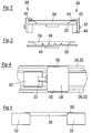
- Fig. 2 shows a support 36 of a transport mover 32 (not shown), which carries a receptacle designed as a tray 38 for an object (not shown).
- the support 36 has two clamping devices 39 which are designed to fix the tray 38 on the support 36.
- a clamping device 39 has a clamping member 40 which is adjustable in the vertical direction between a fixing position (shown on the right in the picture) and a release position (shown on the left in the picture). The clamping member 40 clamps the tray 38 over an edge 50 of the tray 38 against the support 36, a clamping force being applied in the vertical direction.
- the clamping device 39 also includes an actuating nose 42 which is firmly connected to the clamping member 40.
- the clamping element 40 can be adjusted via the actuating nose 42 by an actuating device arranged on the rail side, for example a run-on slope.
- the clamping device 39 further comprises a bistable locking device 44, by means of which the clamping member 40 can be fixed in two different positions, namely the fixing position and the release position, with respect to the support 36.
- a support 36 which has a non-planar topography in the form of elevations 46.
- a tray 38 with depressions 48 arranged.
- the elevations 46 of the support grip into the suitably shaped depressions 48 of the tray 38 in order to secure the tray 38 on the support 36 against a movement in the horizontal direction.
- a tray 38 is shown in a top view, which rests with its edges 50 on two rails of a guide 52 which also forms a support for the tray 38 at the same time.
- the guide 52 guides the tray 38 as it moves in a direction that is horizontal in the image, that is, along the guide rails.
- the tray 38 is secured by the guide 52 against leaving the path of movement, that is to say against a movement in the vertical direction in the image.
- a transport mover 32 is shown between the rails of the guide 52.
- the transport mover 32 is movable in the horizontal direction in the picture along a movement path.
- the transport mover 32 projects above the tray 38 in height, that is to say in the direction out of the image plane, or it projects above at least one embodiment of the tray in height.
- Fig. 5 shows a tray 38 which is carried by two transport movers 32.
- the transport movers 32 thus jointly form a support for the tray 38.
- the tray 38 rests with its edges 50 on the transport movers 32 or on attachment parts of the transport movers 32 provided for this purpose.
- the tray 38 is arranged and held with a depth between the transport movers 32.
- the tray 38 is thus secured in the horizontal and vertical directions relative to the transport movers 32, which move synchronously and at a substantially constant distance during the transport of the tray 38.
- the transport movers 32 are controlled by a control device (not shown) for movement in the horizontal direction in the image, which ensures that the distance between the transport movers 32 remains essentially the same for holding the tray 38. To release or dispense the tray 38, the distance is increased.
- the tray 38 can continue to rest with its edges 50 on the transport movers 32, but in the vertical direction (i.e. upwards) or in the direction perpendicular to the image plane (i.e. transversely to the trajectory) are delivered by the transport movers 32.
- the tray 38 can slide out between the transport movers 32 in a curve in the direction perpendicular to the plane of the image or be pushed out laterally at any point in the track system 34 by means of an ejector device.
- the distance can also be increased by a large amount so that the tray 38 can fall down or can also be lifted up in order to be delivered by the transport movers 32.
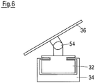
- Fig. 6 shows a transport mover 32 guided in a rail system 34, the support 36 of which can be tilted to the left and right about a tilt bearing 54.
- the axis of inclination of the inclination bearing 54 runs parallel to the movement path of the transport mover 32, i.e. perpendicular to the image plane in the illustration, and through the center of the inclination bearing 54.
- the support 36 can therefore be inclined, for example, to compensate for a centrifugal force that occurs when the transport mover 32 turns a curve an object (not shown) carried by the support 36 acts.
- the inclination of the support 36 can be brought about, for example, by drive means of the transport mover 32 arranged in the inclination bearing 54 or by a pendulum mass firmly connected to the support 36.
- the pendulum mass and the overall center of gravity of the inclinable device part are preferably below the inclination axis, so that when the transport mover 32 is cornering, the support 36 is inclined in the direction of the interior of the curve.
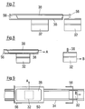
- FIG. 7 two transport movers 32 are shown in a sectional side view, which are arranged horizontally movably in the picture in a track system 34, not shown.
- the transport mover 32 shown on the left has a support 36 for carrying a tray 38.
- the tray 38 is secured against horizontal displacement relative to the transport movers 32 by delimitations 56.
- One of the boundaries 56 namely the one shown on the right, is formed on the transport mover 32 shown on the right.
- the transport movers 32 are in a fixed position relative to one another and are kept at essentially the same distance from one another by a control device (not shown) during transport of the tray 38.
- the transport movers 32 thus jointly fix the tray 38 during transport.
- Fig. 8 are the transport movers 32 of the Fig. 7 shown in a release position.
- the transport mover 32 shown on the right was moved to the right relative to the transport mover 32 shown on the left and the distance between the two transport movers 32 was increased.
- the boundary 56 of the transport mover 32 shown on the right does not secure the tray 38 in this position.
- the tray 38 can therefore be delivered by the transport mover 32 shown on the left in the delivery direction A, that is to say in the horizontal direction to the right.
- the delivery direction A here runs parallel to the transport direction B of the transport movers 32.
- Fig. 9 shows an alternative embodiment of two transport movers 32, which are designed to move a tray 38 together.
- the transport movers 32 move in a rail system 34 along a transport direction B and are in FIG Fig. 9 shown in a release position.
- the transport mover 32 indicated by dashed lines on the left (because it is covered), carries a tray 38 with an edge 50 and has an L-shaped delimitation 56 for the tray 38.
- the tray 38 can be delivered in the delivery direction A, that is to say transversely to the transport direction B, for example by means of a centrifugal force when the transport mover 32 shown on the left is cornering.
- the transport mover 32 shown on the right also has a delimitation 56 which, in a fixed position (not shown), together with the delimitation 56 of the transport mover 32 shown on the left, the tray 38 against a movement transverse to the transport axis B relative to the track system 34 and against a movement parallel to the transport direction B relative to the transport movers 32 secures.
- FIG. 11 shows an alternative embodiment of two transport movers 32 which are designed to carry and secure a tray 38.
- the transport movers 32 are movably driven and guided in a rail system 34 and are in Fig. 10 shown in a fixing position.
- the transport mover 32 shown on the left has a support 36 for the tray 38 and a delimitation 56.
- the transport mover 32 shown on the right also has a delimitation 56.
- Two different formats of trays 38, which rest on the support 36 and are secured by the boundaries 56, are indicated by dash-dot lines.
- the boundaries 56 have a rectangular basic shape with beveled corner areas, so that trays 38 of different sizes or of different shapes can be reliably secured on the support 36.
- a format changeover can be carried out very easily in that, among other things, the distances between the transport movers 32 in the rail system 34 are adjusted accordingly by means of the control device.
- Fig. 11 are the transport movers 32 of the Fig. 10 shown in a release position.
- the transport movers 32 thus have in relation to the fixing position of the Fig. 10 a greater distance to each other.
- a tray 38 is therefore no longer secured by the boundaries 56 on the support 36.
- the tray 38 can thus be delivered in a delivery direction A transverse to the transport direction B of the transport movers 32.
- FIG. 12 The embodiment of the Figures 10 and 11 is in Fig. 12 shown in a side view.
- the two transport movers 32 can be moved horizontally along the track system 34 and are shown in the release position.
- the tray 38 rests on the support 36 of the transport mover 32 shown on the left.
- the boundaries 56 of the transport movers 32 do not secure the tray 38 in this release position, so that the tray 38 can be released in a direction perpendicular to the image plane.
- Fig. 13 shows a plan view of an embodiment of a two-part support 36, one part of which is carried by a respective transport mover 32 hidden in the image.
- the support 36 is delimited by delimitations 56 for a tray 38 (not shown) which are arranged at the front and rear with respect to the direction of movement.
- the two parts of the support 36 are movable relative to one another with their respective transport movers 32 and form complementary contact lines on their side facing the respective other part.
- These complementary contact lines or the parts of the support 36 are formed at an angle in such a way that a, for example, rectangular tray 38 is supported on the support 36, although the parts of the support 36 are at a distance from one another. A falling of the tray 38 can thus be reliably prevented even when the transport movers 32 are in a release position.
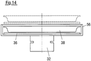
- a transport mover 32 with a support 36 for a tray 38 is shown in a sectional view, which moves in a transport direction B perpendicular to the image plane along a path system 34, not shown.
- the support 36 and the tray 38 are surrounded by a delimitation 56 so that the tray 38 is secured against movement in the horizontal direction.
- the support 36 can be raised into a release position indicated by dashed lines and can be lowered out of this.
- the tray 38 can thus be lifted out of the effective area of the delimitation 56 by lifting the support 36 in order to be in the release position to be delivered.
- the delimitation 56 forms a temporary frame for the tray 38 which disappears when the support 36 is raised.
- Fig. 15 shows a transport mover 32 which is also movable perpendicular to the plane of the drawing and which carries a tray 38 on a support 36 in a sectional view.
- the support 36 has spring clips 58 which can be bent downwards by a rail-side actuating device 60, such as a run-up slope or ramp, as indicated by dashed lines on the right-hand side in the figure.
- the spring clips 58 limit the tray 38 against movement in the horizontal direction transverse to the transport direction B of the transport mover 32.
- the tray 38 In the release position indicated by dashed lines, the tray 38 is not secured against such movement and can be transverse to the transport direction B. be handed in.
- the tray 38 is secured against a movement along the transport direction B relative to the transport mover 32 by a delimitation 56.
- Fig. 16 shows the transport mover 32 of FIG Fig. 15 in a top view.
- the elements of the transport mover 32 covered by the tray 38 are indicated by dashed lines.
- the transport mover 32 forms a support 36, the spring clips 38 forming part of the support 36, while the remaining part of the support 36 is designed to be rigid.
- the tray 38 is fixed against a movement in the vertical direction in the image by means of boundaries 56. After the spring clip 58 has been deformed into a release position, the tray 38 can be delivered in the delivery direction A transversely to the transport direction B, that is, in the horizontal direction in the image.
- the spring clips 58 can be arranged in the transverse direction and / or in the longitudinal direction, as shown, wherein one or more spring clips 58 can be arranged on each side.
- the spring clips 58 of the transport mover 32 can also serve alone as a support 36 and / or as a carrier for the tray 38 and can be bent downward by an external, that is to say on the rail side, force influence, see above that the tray 38 can be pushed off the support 36. It is understood that in the embodiment of Figures 15 and 16 the spring clips 58 shown on the left can also be bent so that the tray 38 can be released or pushed off to the left.
- a transport mover 32 is shown with a support 36 for a tray 38, which is surrounded by a boundary 56 and is therefore indicated by dashed lines.
- the delimitation 56 is rotatable about an axis of rotation D, which runs perpendicular to the image plane and parallel to the transport direction B.
- the limitation 56 is shown in its starting position, that is, a fixing position.
- Fig. 18 is the boundary 56 of the transport mover 32 of the embodiment of FIG Fig. 17 rotated, so in a release position, shown.
- the delimitation 56 was rotated about the axis of rotation D, for example by actuating means arranged on the path system 34, not shown.
- the delimitation 56 no longer limits the tray 38 with respect to a movement transverse to the transport direction B, that is to say in the horizontal direction in the image.
- the tray 38 can thus be dispensed in a dispensing direction A to the left or right of the support 36.
- the tray 38 rests on the support 36 as a rigid plate fixed on the transport mover 32.
- the boundary 56 can also be formed as an enclosure, frame, grid, rods and the like and is rotatably mounted at two opposite points on the support 36 or on the carrier of the transport mover 32.
- the tray 38 can in the fixing position of the Fig. 17 placed from above and / or included in the limitation 56 and in the release position of Fig. 18 pushed off to one side or taken up from one side.
- the delimitation 56 can, for example, be held in the fixing position by a spring force or can be fixed in the fixing position by a latching means (releasable from the outside).
- the actuating means on the railroad side can, for example, cause the delimitation 56 to rotate or pivot mechanically, pneumatically and / or magnetically.
- a support 36 for carrying a tray 38 is shown, which is designed to be deformable.
- the tray 38 deforms the support 36 by its own weight in such a way that one or more displacement sections 64 are formed around the tray 38.
- the displacement sections 64 secure the tray 38 against movement in the horizontal direction.
- the tray 38 thus forms its own bed in the support 36, which bed is adapted to the shape of the tray 38.
- the molding process can be reinforced or supported, for example, by additionally pressing the tray 38 into the support 36.
- the displacement sections 34 form a delimitation in order to accommodate the tray 38.
- Fig. 20 is the edition 36 of the Fig. 19 shown after it has been subjected to a force from two sides by jaws 66 of an actuating device in order to be placed in a release position.
- the tray 38 was lifted out of its bed, the bed, the displacement sections 64 and the boundary for the tray 38 having disappeared.
- the support 36 was deformed by the jaws 66 in such a way that the surface of the support 36 facing the tray 38 bulges upward, the displacement sections 64 forming a boundary, which the tray 38 in Fig. 19 secure horizontally, have disappeared.
- the support 36 can also be stronger than in Fig. 20 A force or pressure can be applied to the tray 38, so that the surface of the support 36 facing the tray 38 curves further, in particular convexly, upwards in order to further simplify the discharge of the tray 38 from the support 36.
- a track 78 of the track system two associated transport movers 32 are shown, each of which has a laterally protruding support area 72 for trays 38 to be transported (indicated by way of example by a dot-dash circle).
- the supports of these two movers 32 that provide these support areas 72 are each shown in FIG Essentially L-shaped and mirror-inverted to one another. In this way, in the area of the track system 78 comprising the guides 76, there is a free space between the movers 32 even when the two supports with their protruding support areas 72 correspond to the situation in FIG Fig. 21 provide a coherent total support surface for the trays 38, or if necessary interrupted by a small gap.
- FIG. 22 Shown embodiment corresponds to that of Fig. 21 , whereby each mover 32 is additionally provided with a delivery aid 74 designed as a scraper or clearer.
- the wipers 74 are each fastened to the one mover 32 and extend towards the support area 72 of the other mover 32, so that when the two movers 32 move apart with the trays 38, they are in a desired manner depending on the configuration of the wipers 74, among other things Cooperate in a way.
- the scrapers 74 can each be rigid and their outreach can be at least substantially adapted to the relative travel path of the two movers 32. Alternatively or additionally, the wiper 74 extending towards a support area 72 can move with this support area 72 when the two movers 32 are moved away from one another.
- the strippers 74 can be elastically deflectable in order to be able to yield when the movers 32 move apart, for example when they come into contact with the trays 38 and the trays 38 are then still partially resting on the support area (s) 72.
- the design and arrangement of the scrapers 74 also depends on the nature of the respective trays 38. It is also possible to comb the support areas 72 by means of the scrapers 74. The scrapers 74 can in principle interact with the trays 38 in any height position.
- blade-like or wire-like scrapers 74 which are moved through between the underside of the trays 38 and the upper side of the support areas 72 when the movers 32 are moved apart in order to close the trays 38 from the support areas 72 if necessary separate or detach, so that the support areas 72 can be better moved away from under the trays 38.
- a fixing device which is stationary in the direction of movement of the movers 32 can be provided, e.g. has a frame-like structure and in the area of the respective delivery position of the trays 38 can be lowered onto a tray resting on the common support area of the two movers 32 and engages around or over this tray.
- a fixing frame can be placed around the tray.
- the moving apart of the movers 32 preferably takes place simultaneously in so far as the two movers 32 are each moved at the same speed and over the same distance in opposite directions. -.-.-.
Description
Die Erfindung betrifft eine Vorrichtung zum Bewegen von Objekten mittels in einem Bahnsystem geführter Transportmover, sowie ein System aus einer derartigen Vorrichtung und einer Aufnahme für ein zu bewegendes Objekt.The invention relates to a device for moving objects by means of transport movers guided in a rail system, as well as a system comprising such a device and a receptacle for an object to be moved.
Derartige Vorrichtungen und Systeme werden, z.B. in der Lebensmittelindustrie, eingesetzt, um Objekte, wie z.B. Wurst- oder Käsescheibenstapel, zwischen verschiedenen Be- und Verarbeitungsstationen zu bewegen bzw. zu transportieren. Dabei stellt die Übergabe des Objekts von der Verarbeitungsstation an den Transportmover oder von dem Transportmover an eine weitere Verarbeitungsstation eine besondere Herausforderung dar. Denn häufig sind die Objekte mechanisch empfindlich, haften an einer Auflagefläche aufgrund ihrer fettigen Oberfläche und sind mechanisch nachgiebig, so dass eine Handhabung erschwert wird. Daher muss zur Handhabung häufig auf eine technisch aufwändige Lösung, z.B. unter Verwendung eines Roboters, zurückgegriffen werden, um die Objekte behutsam und dennoch mit ausreichender Geschwindigkeit zwischen einer Verarbeitungsstation und einem Transportmover zu übergeben. Dies gilt insbesondere, aber nicht nur, bei der Übergabe von dem Transportmover an eine weitere Verarbeitungsstation, also für den Vorgang der Abgabe des Objekts von dem Transportmover. Eine Vorrichtung zum Transportieren von Objekten ist beispielsweise in der
Es ist die Aufgabe der Erfindung, bei einer Vorrichtung zum Bewegen von Objekten der eingangs genannten Art die Übergabe von Objekten von dem oder an den Transportmover zu vereinfachen.It is the object of the invention to simplify the transfer of objects from or to the transport mover in a device for moving objects of the type mentioned at the beginning.
Diese Aufgabe wird durch eine Vorrichtung mit den Merkmalen des Anspruchs 1 gelöst.This object is achieved by a device with the features of
Gemäß diesem Aspekt der Erfindung ist also eine transportmoverseitige Auflage für die Aufnahme vorgesehen.According to this aspect of the invention, a support on the transport mover side is provided for the recording.
Ein Vorteil der Erfindung besteht generell darin, dass beim Aufnehmen bzw. Auflegen der Aufnahme auf die Auflage kein Rahmen überwunden werden muss. So wird die Vorrichtung zum Bewegen von Objekten vereinfacht. Auch das Abgeben der Aufnahmen von dem Transportmover wird erleichtert, weil zumindest zeitweise kein Rahmen im Weg ist. Die Aufnahmen werden aber dennoch dann, wenn es erforderlich ist, sicher auf der Auflage des Transportmovers durch die Fixiermittel gehalten. Erforderlich ist ein Halten einer Aufnahme auf der Auflage zeitweise während des Transports, also während sich der betreffende Transportmover in dem Bahnsystem bewegt, und zwar vor allem dann, wenn die Aufnahme bzw. ein darin befindliches Objekt beschleunigt wird, und zwar sowohl in Bewegungsrichtung als auch bei Kurvenfahrten durch Fliehkräfte.One advantage of the invention is generally that no frame has to be overcome when the receptacle is picked up or placed on the support. Thus, the device for moving objects is simplified. The transfer of the recordings from the transport mover is also made easier because at least temporarily there is no frame in the way. However, if necessary, the recordings are still held securely on the support of the transport mover by the fixing means. It is necessary to hold a recording on the support temporarily during transport, i.e. while the transport mover in question is moving in the rail system, especially when the recording or an object located therein is accelerated, both in the direction of movement and when cornering due to centrifugal forces.
Die Fixiermittel sind insbesondere auch zum Fixieren der Aufnahme auf der Auflage beim Aufnehmen und/oder zum Freigeben der Aufnahme beim Abgeben von der Auflage ausgestaltet.The fixing means are also designed in particular to fix the receptacle on the support when it is picked up and / or to release the receptacle when it is released from the support.
Wie bereits erwähnt, handelt es sich bei der Erfindung bei den zu bewegenden Objekten insbesondere um Lebensmittelprodukte, vorzugsweise um Portionen aus einer oder mehreren Scheiben, die von einem Produkt, z.B. einem Wurst- oder Käselaib, abgeschnitten werden, beispielsweise mittels eines Hochleistungsslicers. Bei den Aufnahmen für die Portionen kann es sich insbesondere um Verpackungsunterteile handeln, die auch als Trays bezeichnet werden. Die Portionen werden entweder durch geeignete Handhabungsmittel in die Trays eingelegt oder direkt in die Trays hinein geschnitten.As already mentioned, in the invention the objects to be moved are in particular food products, preferably portions made up of one or more slices, which are made up of a product, e.g. a sausage or cheese loaf, for example by means of a high-performance slicer. The receptacles for the portions can in particular be lower packaging parts, which are also referred to as trays. The portions are either placed in the trays by suitable handling means or cut directly into the trays.
Die Handhabung von Verpackungsteilen bzw. Trays und damit gewissermaßen ein indirekter Umgang mit den Lebensmittelportionen ist gegenüber einer direkten Handhabung der Lebensmittel unter hygienischen Gesichtspunkten vorteilhaft.The handling of packaging parts or trays and thus, to a certain extent, indirect handling of the food portions is advantageous compared to direct handling of the food from a hygienic point of view.
Wie dem Fachmann grundsätzlich bekannt ist, können Trays - oder allgemein Teile bzw. Unterteile von für Lebensmittelportionen wie z.B. Wurst- oder Käsescheiben zum Einsatz kommenden Verpackungen - beispielsweise aus einer Kunststofffolie in einem Tiefziehverfahren hergestellt werden. Derartige Trays sind insbesondere formstabil. Bei den Trays kann es sich auch um Kunststoff-Formteile oder um insbesondere geschäumte Formkörper handeln. Die Verpackungen bzw. Trays können in einer großen Vielfalt an Formen, Formaten und Größen hergestellt werden. Trays können einen erhöhten Randbereich aufweisen, tablettartig und/oder zumindest im Wesentlichen eben ausgeführt sein.As is fundamentally known to the person skilled in the art, trays or, in general, parts or sub-parts of food portions such as e.g. Sausage or cheese slices are used in packaging - for example made from a plastic film in a deep-drawing process. Such trays are particularly dimensionally stable. The trays can also be molded plastic parts or, in particular, foamed molded bodies. The packaging or trays can be produced in a wide variety of shapes, formats and sizes. Trays can have a raised edge area, be designed like a tray and / or at least essentially flat.
Gemäß der Erfindung umfassen die Transportmover jeweils zumindest einen mit dem Bahnsystem zusammenwirkenden Läufer, wobei zumindest ein und insbesondere jeder Transportmover wenigstens einen am Läufer angebrachten Träger umfasst, der die rahmenfreie Auflage bildet oder mit der rahmenfreien Auflage verbunden ist.According to the invention, the transport movers each comprise at least one runner interacting with the rail system, at least one and in particular each transport mover comprising at least one carrier attached to the runner, which forms the frameless support or is connected to the frameless support.
Das Objekt kann eine Verpackung oder einen Teil einer Verpackung, wie z.B. einen sogenannten Tray, umfassen.The object can be a package or part of a package, e.g. a so-called tray.
Der Antrieb für die Transportmover kann beispielsweise als Linearmotor ausgebildet sein, insbesondere als linearer Synchronmotor oder als linearer Induktionsmotor.The drive for the transport movers can for example be designed as a linear motor, in particular as a linear synchronous motor or as a linear induction motor.
Derartige Linearmotoren sind im Zusammenhang mit einer Vielzahl von Anwendungen grundsätzlich bekannt. Von Vorteil ist ein derartiges Antriebsprinzip unter anderem dann, wenn vergleichsweise geringe Lasten zu transportieren sind, wie es in dem hier in Rede stehenden Bereich des Transports von Lebensmittelportionen der Fall ist.Such linear motors are known in principle in connection with a large number of applications. Such a drive principle is advantageous, inter alia, when comparatively low loads are to be transported, as is the case in the area of transporting food portions under discussion here.
Ein für die Erfindung grundsätzlich verwendbares Transportsystem, auf das hiermit im Hinblick auf das Erfordernis der Ausführbarkeit der Erfindung ausdrücklich Bezug genommen wird, wird von der Firma MagneMotion Inc. mit Sitz in Devens, Massachusetts, USA, angeboten. Dieses System basiert auf einem sogenannten LSM-Antrieb, also auf einem Antrieb durch lineare Synchronmotoren, der von einem sogenannten linearen Induktionsmotor (LIM-Antrieb) zu unterscheiden ist. Im Unterschied zu einem LIM-Antrieb wird bei einem LSM-Antrieb ein Magnetfeld nicht mittels des sogenannten elektromagnetischen Wanderfeldes induziert, sondern das Magnetfeld wird durch Permanentmagnete bereitgestellt. Wenn der Läufer des Linearmotors die Permanentmagnete trägt und der Stator des Linearmotors das elektromagnetische Wanderfeld erzeugt, dann kann man sich das Antriebsprinzip eines LSM-Antriebs bildlich so vorstellen, dass der mit dem Permanentmagneten versehene Transportmover von dem sich längs des Stators bewegenden Magnetfeld über die Transportstrecke gezogen wird. Ein solches Transportsystem bzw. Antriebsprinzip ist beispielsweise in
Das Bahnsystem bzw. die einzelnen Bahnen eines solchen Transportsystems können in eine Vielzahl aufeinanderfolgender Bahnelemente unterteilt werden, die gewissermaßen jeweils einen Einzel-Linearmotor bilden und von einer Steuereinrichtung individuell ansteuerbar sind. Wenn gleichzeitig die im Bahnsystem befindlichen Transportmover mittels der Steuereinrichtung identifizierbar sind, dann können auf diese Weise grundsätzlich beliebig viele Transportmover gleichzeitig in einem grundsätzlich beliebig komplexen Bahnsystem betrieben und dabei individuell bewegt werden.The track system or the individual tracks of such a transport system can be subdivided into a multiplicity of successive track elements, which each form a single linear motor, so to speak, and can be individually controlled by a control device. If, at the same time, the transport movers located in the rail system can be identified by means of the control device, then in this way, in principle, any number of transport movers can be operated simultaneously in a fundamentally complex rail system and can be moved individually.
Für die Identifizierung bzw. Lokalisierung der einzelnen Transportmover im Bahnsystem verwendet die vorstehend erwähnte Firma MagneMotion Inc. eine Technik, bei der jeder Transportmover mit einem Transducer versehen ist, der in den vom Bahnsystem gebildeten Stator ein Signal induziert, wodurch es der Steuereinrichtung ermöglicht wird, die exakte Position des Transportmovers mit einer von der Größe des Gesamtsystems abhängigen Genauigkeit von Bruchteilen eines Millimeters oder Bruchteilen eines Zentimeters zu bestimmen. Ein Vorteil dieses Systems besteht darin, dass keine externen Sensoren benötigt werden. Bei dem Steuersystem der Firma MagneMotion Inc. ist außerdem durch eine Unterteilung der Bahnen in eine Vielzahl von - gewissermaßen jeweils einen Einzel-Linearmotor darstellenden - Bahnelementen sichergestellt, dass keine Kollisionen zwischen aufeinanderfolgenden Transportmovern auftreten. So kann ein Transportmover nur dann in das nächste Bahnelement einfahren, wenn dies von der Steuereinrichtung gestattet wird, was insbesondere dann nicht der Fall ist, wenn sich ein anderer Transportmover in dem Bahnelement befindet.For the identification or localization of the individual transport movers in the rail system, the aforementioned company MagneMotion Inc. uses a technology in which each transport mover is provided with a transducer which induces a signal in the stator formed by the rail system, which enables the control device to to determine the exact position of the transport mover with an accuracy of fractions of a millimeter or fractions of a centimeter, depending on the size of the overall system. One advantage of this system is that no external sensors are required. In the control system from MagneMotion Inc., a subdivision of the tracks into a large number of track elements - each representing a single linear motor, so to speak - ensures that no collisions occur between successive transport movers. A transport mover can only move into the next track element if this is permitted by the control device, which is particularly not the case if another transport mover is located in the track element.
Vor dem Hintergrund dieses grundsätzlich bekannten Transportsystems ist bei der Erfindung in einem möglichen Ausführungsbeispiel vorgesehen, dass das Bahnsystem als Stator des Linearmotors ausgebildet ist.Against the background of this basically known transport system, one possible embodiment of the invention provides that the track system is designed as a stator of the linear motor.
Insbesondere ist der Läufer jeweils ein Bestandteil eines linearen Synchronmotors, wobei insbesondere der Läufer zumindest einen Permanentmagneten umfasst und das Bahnsystem als Motorstator ausgebildet ist.In particular, the rotor is in each case a component of a linear synchronous motor, the rotor in particular comprising at least one permanent magnet and the track system being designed as a motor stator.
Vorzugsweise ist das Bahnsystem in eine Vielzahl von, insbesondere jeweils einen Einzel-Linearmotor darstellenden, Bahnelementen unterteilt, die von der Steuereinrichtung individuell ansteuerbar sind.The track system is preferably subdivided into a plurality of track elements, in particular each representing a single linear motor, which can be controlled individually by the control device.
Die Transportmover sind vorzugsweise von der Steuereinrichtung identifizierbar.The transport movers can preferably be identified by the control device.
Des Weiteren sind die Transportmover vorzugsweise von der Steuereinrichtung im Bahnsystem lokalisierbar.Furthermore, the transport movers can preferably be localized by the control device in the rail system.
Das Transportsystem weist eine Mehrzahl von Transportmovern auf, deren Gesamtanzahl von der jeweiligen Anwendung abhängig ist. Es kann vorgesehen sein, dass das Bahnsystem mehrere Dutzende bis einige Hundert Transportmover umfasst, d.h. es kann gewissermaßen ein regelrechter "Schwarm" von Transportmovern im Bahnsystem vorhanden sein, um eine Vielzahl von Portionen zu transportieren und gegebenenfalls Zusatzfunktionen durchzuführen wie z.B. eine Pufferung, ein Verteilen und/oder ein Zuordnen von Portionen.The transport system has a plurality of transport movers, the total number of which depends on the respective application. It can be provided that the rail system comprises several tens to several hundred transport movers, i. to a certain extent there can be a real "swarm" of transport movers in the rail system in order to transport a large number of portions and, if necessary, carry out additional functions such as e.g. buffering, distributing and / or allocating portions.
Im Rahmen der Erfindung kann ein zu bewegendes Objekt z.B. ein Produkt, ein Lebensmittelprodukt und/oder einen Stapel oder - allgemein - eine Portion aus z.B. Wurst- oder Käsescheiben umfassen. Auch kann ein Objekt ein Tray, eine Folie, eine Platte, ein Behältnis und/oder einen Schlauchbeutel, jeweils insbesondere zur Aufnahme eines Lebensmittelproduktes, umfassen.In the context of the invention, an object to be moved can e.g. a product, a food product and / or a stack or - in general - a portion of e.g. Include sausage or cheese slices. An object can also comprise a tray, a film, a plate, a container and / or a tubular bag, in each case in particular for receiving a food product.
Im Rahmen der Erfindung ist der Begriff "Portion" breit zu verstehen. Eine Portion kann dementsprechend aus nur einer einzigen Scheibe bestehen. Alternativ kann eine Portion mehrere Scheiben umfassen, die in einer grundsätzlich beliebigen Relativanordnung vorliegen können, beispielsweise in einer sogenannten Stapel- oder Schindelanordnung, wie sie auf dem hier in Rede stehenden technischen Gebiet dem Fachmann bekannt sind. Bei der Portion kann es sich um eine Gesamtportion handeln, wie sie abschließend verpackt und im Handel angeboten wird. Alternativ kann die Portion eine Teilportion sein, die erst zusammen mit einer oder mehreren weiteren Teilportionen, die wiederum jeweils eine oder mehrere Scheiben umfassen können, eine Gesamtportion bildet. Die Teilportionen einer Gesamtportion können aus unterschiedlichen Produktsorten gebildet sein, so dass durch Zusammenstellen mehrerer Teilportionen eine Mehrsorten-Portion erzeugt werden kann und nach deren Verpackung somit eine Mehrsorten-Packung vorliegt. Bei den Scheiben kann es sich beispielsweise um vergleichsweise dünne Scheiben handeln, wie sie in Form von Wurst- oder Käseaufschnitt allgemein bekannt sind. Alternativ kann es sich bei den Scheiben jeweils um im Vergleich zu Aufschnitt relativ dicke Stücke wie beispielsweise Frischfleischstücke handeln.In the context of the invention, the term “portion” is to be understood broadly. A portion can therefore consist of just one single slice. Alternatively, a portion can comprise several slices, which in principle can be in any Relative arrangements can be present, for example in a so-called stacking or shingle arrangement, as is known to the person skilled in the art in the technical field in question here. The portion can be a total portion as it is finally packaged and offered in stores. Alternatively, the portion can be a partial portion which only forms a total portion together with one or more further partial portions, which in turn can each comprise one or more slices. The sub-portions of a total portion can be formed from different types of product, so that a multi-type portion can be produced by combining several sub-portions and a multi-type pack is thus present after its packaging. The slices can be, for example, comparatively thin slices, as are generally known in the form of cold cuts or cheese. Alternatively, the slices can each be pieces that are relatively thick compared to cold cuts, such as pieces of fresh meat.
Mit anderen Worten handelt es sich bei Anwendungen im Lebensmittelbereich im Rahmen der Erfindung bei einer Portion um die im Hinblick auf die Transportaufgabe kleinste Einheit, die einerseits über eine bestimmte Strecke transportiert werden muss und die gegebenenfalls - je nach Anwendung - andererseits zusätzlich zu weiteren Portionen in Beziehung gesetzt werden muss, um die jeweiligen Anforderungen der Gesamtanlage, die eine oder mehrere Aufschneidevorrichtungen, insbesondere Slicer, das Bahnsystem sowie eine oder mehrere Verpackungsvorrichtungen umfasst, zu erfüllen, beispielsweise hinsichtlich der Bildung von Formaten, wie sie für die jeweils vorgesehene Verpackungsvorrichtung bereitgestellt werden müssen.In other words, for applications in the food sector within the scope of the invention, a portion is the smallest unit with regard to the transport task, which on the one hand has to be transported over a certain distance and which, if necessary - depending on the application - on the other hand, in addition to further portions Relationship must be set in order to meet the respective requirements of the overall system, which includes one or more slicing devices, in particular slicers, the web system and one or more packaging devices, for example with regard to the formation of formats as they have to be provided for the respective packaging device .
Ein Transportmover kann ein bzw. eine oder mehrere Objekte bzw. Portionen transportieren. Alternativ ist es auch möglich, dass mehrere, insbesondere zwei, Transportmover gemeinsam ein Objekt transportieren. Die Transportmover können dabei gewissermaßen gemeinsam auf dem Bahnsystem als Einheit bewegt werden. Auf diese Weise können auch größere Lasten, insbesondere schwerere und/oder flächenmäßig größere Objekte, auf dem Bahnsystem bewegt werden, als mit nur einem Transportmover.A transport mover can transport one or more objects or portions. Alternatively, it is also possible for several, in particular two, transport movers to jointly transport an object. The transport movers can be moved together as a unit on the rail system become. In this way, larger loads, in particular heavier and / or larger objects in terms of area, can be moved on the rail system than with just one transport mover.
Gemäß einer Ausführung ist vorgesehen, dass die Fixiermittel eine Lagerung oder Aufhängung für die Auflage am Transportmover umfassen, die dazu ausgebildet ist, eine Änderung der Orientierung der Auflage, insbesondere eine Neigung der Auflage, relativ zum Transportmover zuzulassen, wobei insbesondere die Lagerung eine pendelartige Lagerung und/oder die Aufhängung eine kardanische Aufhängung für die Auflage umfasst.According to one embodiment, it is provided that the fixing means comprise a mounting or suspension for the support on the transport mover, which is designed to allow a change in the orientation of the support, in particular an inclination of the support, relative to the transport mover, with the mounting in particular being a pendulum-like mounting and / or the suspension comprises a cardanic suspension for the support.
Auf diese Weise ist es insbesondere möglich, dass die Lagerung durch Neigen bzw. Schrägstellen der Auflage bzw. eines Trägers des Transportmovers Fliehkräfte, die auf die zu transportierende Aufnahme bzw. auf das zu transportierende Objekt wirken, kompensieren kann.In this way, it is particularly possible for the mounting to compensate for centrifugal forces acting on the receptacle to be transported or on the object to be transported by tilting or tilting the support or a carrier of the transport mover.
Da eine solche Lagerung bzw. Aufhängung dazu in der Lage ist, eine Aufnahme bzw. ein Objekt auf dem Transportmover zu halten, d.h. eine Maßnahme darstellt, ohne die die Aufnahme bzw. das Objekt Gefahr liefe, vom Transportmover zu fallen, stellt eine solche Lagerung bzw. Aufhängung Fixiermittel im Sinne der Erfindung dar.Since such a mounting or suspension is able to hold a receptacle or an object on the transport mover, i. E. represents a measure without which the receptacle or the object would run the risk of falling from the transport mover, such a storage or suspension represents fixation means within the meaning of the invention.
Bei einer Ausführungsform ist eine fliehkraftgestützte Einrichtung zum Abgeben der Aufnahme von der Auflage vorgesehen. Dadurch können z.B. während einer Kurvenfahrt ohnehin vorhandene Kräfte zum Abgeben des Objekts genutzt werden. Dies kann beispielsweise durch eine Lücke in einer bahngestützten Leitplanke für das Objekt oder durch einen sich zeitweise öffnenden oder verschwindenden Rahmen für das Objekt oder durch Überschreitung einer Haftreibung zwischen der Auflage und einem Bodenbereich des Objekts bewirkt werden.In one embodiment, a centrifugal force-assisted device is provided for releasing the receptacle from the support. In this way, for example, forces which are already present during cornering can be used to transfer the object. This can be brought about, for example, by a gap in a rail-supported guardrail for the object or by a frame for the object that opens or disappears at times, or by exceeding static friction between the support and a floor area of the object.
Bei einer Ausführungsform sind die Fixiermittel zur Erzeugung einer Haltekraft ausgebildet, die im Wesentlichen in horizontaler Richtung und/oder in einer zur Transportrichtung parallelen Ebene wirksam ist. Dadurch wird das Objekt gegen seitliches Verrutschen und ungewolltes Abgeben gesichert. Insbesondere wirken dabei die Fixiermittel selbst mit einer Kraft, die im Wesentlichen vertikal, nämlich insbesondere in Richtung der Auflage, insbesondere nach unten, gerichtet ist.In one embodiment, the fixing means are designed to generate a holding force which is effective essentially in the horizontal direction and / or in a plane parallel to the transport direction. This secures the object against slipping sideways and unintentional dropping. In particular, the fixing means themselves act with a force which is essentially vertical, namely in particular in the direction of the support, in particular downwards.
Bei einer Ausführungsform sind die Fixiermittel dazu ausgebildet, die Aufnahme durch Reibschluss zu fixieren, wobei insbesondere die Fixiermittel in Form einer reibungserhöhenden Oberfläche der rahmenfreien Auflage vorgesehen sind. Dies stellt eine einfache Art der Fixierung bei Verwendung einer rahmenfreien Auflage dar, und das Objekt wird besser auf der Auflage gesichert. Die reibungserhöhende Oberfläche kann z.B. ein elastomeres Material, ein Gummi und/oder eine raue Oberfläche umfassen.In one embodiment, the fixing means are designed to fix the receptacle by frictional engagement, the fixing means in particular being provided in the form of a friction-increasing surface of the frameless support. This is an easy way of fixing when using a frameless support, and the object is better secured on the support. The friction-increasing surface can e.g. comprise an elastomeric material, a rubber and / or a rough surface.
Bei einer Ausführungsform sind die Fixiermittel dazu ausgebildet, die Aufnahme durch Anhaften zu fixieren, wobei insbesondere die Fixiermittel in Form einer Haft- oder Klebeschicht oder in Form einer oder mehrerer vereinzelter Haft- oder Klebestellen auf der rahmenfreien Auflage vorgesehen sind. Dadurch wird die Sicherung des Objekts auf der Auflage weiter verbessert.In one embodiment, the fixing means are designed to fix the receptacle by adhering, in particular the fixing means being provided in the form of an adhesive or adhesive layer or in the form of one or more individual adhesive or gluing points on the frameless support. This further improves the security of the object on the support.
Bei einer Ausführungsform sind die Fixiermittel dazu ausgebildet, die Aufnahme mittels Unterdruck zu fixieren, wobei insbesondere die Fixiermittel wenigstens eine, bevorzugt eine Mehrzahl verteilt angeordneter, Saugeinrichtungen umfassen. Dies stellt eine weitere Möglichkeit dar, die Sicherung des Objekts auf der Auflage in vergleichsweise einfacher und dennoch zuverlässiger Weise weiter zu verbessern.In one embodiment, the fixing means are designed to fix the receptacle by means of negative pressure, with the fixing means in particular comprising at least one, preferably a plurality of, distributed suction devices. This represents a further possibility of further improving the securing of the object on the support in a comparatively simple and yet reliable manner.
Bei einer Ausführungsform sind die Fixiermittel zwischen einer Fixierstellung und einer Freigabestellung für die Aufnahme verstellbar. Die Fixiermittel sind hierbei also gewissermaßen schaltbar, und das Fixieren und das Abgeben des Objekts können selektiv unterstützt werden. Insbesondere sind die Fixiermittel mittels einer zumindest teilweise außerhalb des betreffenden Transportmovers, bevorzugt am Bahnsystem, vorgesehenen Betätigungseinrichtung verstellbar. Dadurch kann eine aktive Betätigungseinrichtung am Transportmover entfallen. Der Transportmover benötigt somit keine eigene Energieversorgung zum Betrieb einer Betätigungseinrichtung und die Vorrichtung wird weiter vereinfacht. Die Betätigungseinrichtung kann z.B. stationär am Bahnsystem angeordnet sein.In one embodiment, the fixing means can be adjusted between a fixing position and a release position for the receptacle. The fixatives are here so to a certain extent switchable, and the fixing and releasing of the object can be selectively supported. In particular, the fixing means can be adjusted by means of an actuating device provided at least partially outside the relevant transport mover, preferably on the rail system. This means that there is no need for an active actuation device on the transport mover. The transport mover thus does not need its own power supply to operate an actuating device and the device is further simplified. The actuating device can for example be arranged in a stationary manner on the rail system.
Bei einer Ausführungsform sind die Fixiermittel durch Passieren einer, insbesondere an der Bahn vorgesehenen, Betätigungsstelle verstellbar. Dies stellt gewissermaßen eine passive Betätigungseinrichtung dar, welche keine besonderen Schaltvorrichtungen z.B. elektromechanischer, hydraulischer oder pneumatischer Art benötigt. Eine Betätigungseinrichtung kann durch einen vorbeifahrenden Transportmover wirksam werden und dabei z.B. in Form einer Anlaufschräge am Bahnsystem ausgeführt sein, welche durch die Bewegung des Transportmovers in Zusammenwirkung mit demselben ein Verstellen der Fixiermittel bewirkt. Die Betätigungsvorrichtung kann aber auch eine Steuerung umfassen und/oder die Verstellung der Fixiermittel z.B. mechanisch und/oder elektromechanisch auslösen. Die Betätigungsstelle kann selbst verstellbar und/oder einstellbar sein.In one embodiment, the fixing means can be adjusted by passing an actuating point, in particular provided on the track. In a sense, this represents a passive actuation device which does not require any special switching devices, e.g. electromechanical, hydraulic or pneumatic type is required. An actuating device can be activated by a transport mover driving past and thereby e.g. be designed in the form of a run-up slope on the track system, which effects an adjustment of the fixing means by the movement of the transport mover in cooperation with the same. The actuating device can also comprise a control and / or the adjustment of the fixing means e.g. trigger mechanically and / or electromechanically. The actuation point can itself be adjustable and / or adjustable.
Bei einer Ausführungsform bilden zwischen einer Fixierstellung und einer Freigabestellung verstellbare Fixiermittel zumindest einen Teil der Auflage. Dabei umfassen die Fixiermittel zum Beispiel einen oder mehrere mittels einer bahnseitigen Schräge oder Rampe in die Freigabestellung biegbare Federbügel. Dadurch lässt sich die Verstellbarkeit der Fixiermittel äußerst einfach dadurch realisieren, dass die Bewegung des Transportmovers in dem Bahnsystem ausgenutzt wird, um die verstellbaren Fixiermittel, beispielsweise elastische Elemente, zu bewegen.In one embodiment, adjustable fixing means between a fixing position and a release position form at least part of the support. The fixing means include, for example, one or more spring clips that can be bent into the release position by means of a slope or ramp on the track side. As a result, the adjustability of the fixing means can be implemented extremely simply by utilizing the movement of the transport mover in the track system to move the adjustable fixing means, for example elastic elements.
Bei einer Ausführungsform umfassen die Fixiermittel eine Klemmeinrichtung, die dazu ausgebildet ist, die Aufnahme an einer oder mehreren Klemmstellen zu fixieren. Das Objekt wird somit besser an der Auflage gesichert.In one embodiment, the fixing means comprise a clamping device which is designed to fix the receptacle at one or more clamping points. The object is thus better secured to the support.
Bei einer Ausführungsform ist die Klemmeinrichtung dazu ausgebildet, die Aufnahme zwischen wenigstens einem, insbesondere verstellbaren, Klemmorgan und der rahmenfreien Auflage einzuklemmen. Dadurch wird die Aufnahme bzw. das Objekt besonders sicher zwischen dem Klemmorgan und der Auflage gehalten. Der Begriff verstellbar kann hier die Bedeutung umfassen, dass sich das Klemmorgan einer zugeordneten Kontaktgeometrie der Aufnahme anpassen kann.In one embodiment, the clamping device is designed to clamp the receptacle between at least one, in particular adjustable, clamping member and the frameless support. As a result, the receptacle or the object is held particularly securely between the clamping member and the support. The term adjustable here can include the meaning that the clamping member can adapt to an associated contact geometry of the receptacle.
Bei einer Ausführungsform ist die Auflage mit einer nichtebenen Topografie als Fixiermittel versehen. Dabei weist die Topografie insbesondere eine oder mehrere Vertiefungen und/oder eine oder mehrere Erhöhungen auf. Dadurch kann die Topografie der Auflage mit einer gegebenenfalls vorhandenen, zumindest teilweise passenden Topografie an einer Unterseite der Aufnahme bzw. des Trays zusammenwirken, um die Aufnahme und somit ein darin aufgenommenes Objekt sicher an der Auflage festzulegen.In one embodiment, the support is provided with a non-planar topography as a fixing means. The topography has in particular one or more depressions and / or one or more elevations. As a result, the topography of the support can interact with a possibly existing, at least partially matching topography on an underside of the receptacle or of the tray in order to securely fix the receptacle and thus an object received therein on the support.
Bei einer Ausführungsform umfassen die Fixiermittel eine oder mehrere Erhöhungen, die in einer Fixierstellung über eine Auflagefläche der Auflage hinaus vorstehen, wobei insbesondere die oder jede Erhöhung zwischen einer Fixierstellung und einer Freigabestellung für die Aufnahme verstellbar und bevorzugt in oder unter die Auflagefläche versenkbar ist. Dadurch lässt sich eine Auflage mit passenden Erhöhungen bzw. zwischen den Erhöhungen vorhandenen Vertiefungen wahlweise festlegen, wodurch die Vorrichtung flexibler einsetzbar ist.In one embodiment, the fixation means comprise one or more elevations that protrude beyond a support surface of the support in a fixation position, wherein in particular the or each elevation between a fixation position and a release position for the receptacle is adjustable and preferably can be lowered into or below the support surface. As a result, a support with matching elevations or depressions present between the elevations can optionally be specified, whereby the device can be used more flexibly.
Bei einer Ausführungsform umfassen die Fixiermittel für zumindest einen Teil einer Auflagefläche der Auflage eine ein- oder mehrteilige Begrenzung oder Einfassung, die relativ zu der Auflagefläche verstellbar ist, insbesondere in zumindest im Wesentlichen vertikaler Richtung. Das Objekt kann somit ohne ein Festklemmen der Aufnahme auf der Auflage gesichert werden. Vorzugsweise ist die Auflagefläche zum Freigeben der Aufnahme anhebbar und zum Fixieren der Aufnahme absenkbar. Hierbei kann die Aufnahme gewissermaßen auf einer Art Lift angeordnet sein, mit dem die Aufnahme auf das jeweils erforderliche Niveau gebracht werden kann.In one embodiment, the fixing means for at least part of a support surface of the support comprise a one-part or multi-part delimitation or border which is adjustable relative to the support surface, in particular at least substantially vertical direction. The object can thus be secured on the support without jamming the receptacle. The support surface can preferably be raised to release the receptacle and lowered to fix the receptacle. Here, the receptacle can be arranged, so to speak, on a type of lift, with which the receptacle can be brought to the respectively required level.
Vorzugsweise erfolgt eine Vertikalbewegung der Auflagefläche durch Beeinflussung von außen her, d.h. mittels entsprechender, insbesondere mechanischer Mittel an einem Bahnabschnitt. Bei diesen Mitteln kann es sich z.B. um Auflaufschrägen oder Rampen handeln.A vertical movement of the support surface is preferably effected by influencing from the outside, i.e. by means of appropriate, in particular mechanical, means on a track section. These means can e.g. be inclines or ramps.
Bei einer Ausführungsform sind die Fixiermittel dazu ausgebildet, die Auflage zumindest zeitweise, insbesondere für Bewegungen in Kurven, zu neigen. Dadurch kann das Objekt festgelegt werden, ohne dass Fixiermittel direkt und mechanisch an dem Objekt angreifen. Das Objekt wird somit geschont und das Abgeben und Aufnehmen des Objekts durch den Transportmover wird deutlich flexibler.In one embodiment, the fixing means are designed to incline the support at least temporarily, in particular for movements in curves. As a result, the object can be fixed without fixing means attacking the object directly and mechanically. The object is thus spared and the transferring and picking up of the object by the transport mover is much more flexible.
Die Neigung wird dabei insbesondere fliehkraftgestützt hervorgerufen. Dies kann z.B. durch ein mit einer neigbar gelagerten Auflage, insbesondere fest, gekoppeltes Pendel erreicht werden, dessen Pendelmasse bei einer Kurvenfahrt aufgrund der Fliehkraft nach außen gedrängt wird, wobei die Pendelmaße insbesondere unterhalb der Neigungsachse angeordnet ist. Eine Neigung der Auflage kann alternativ oder zusätzlich zum Abgeben des Objekts von der Auflage in Verbindung mit der Schwerkraft des Objekts genutzt werden. Des Weiteren kann die Auflage bzw. der Träger zumindest in Teilbereichen des Bahnsystems auch durch entsprechende Führungen geneigt werden. Beispielsweise in Kurven kann eine Auflage bzw. ein Träger auf eine leicht überhöhte Führung auflaufen und dadurch zum Kompensieren von Fliehkräften nach innen geneigt werden.The inclination is particularly caused by centrifugal force. This can be achieved, for example, by a pendulum coupled to an inclinable support, in particular fixedly, the pendulum mass of which is pushed outwards when cornering due to centrifugal force, the pendulum mass being arranged in particular below the inclination axis. An inclination of the support can alternatively or additionally be used to release the object from the support in conjunction with the gravity of the object. Furthermore, the support or the carrier can also be inclined at least in partial areas of the track system by means of appropriate guides. For example, in curves, a support or a carrier can run onto a slightly elevated guide and thereby be inclined inward to compensate for centrifugal forces.
Eine Neigung der Auflage kann nicht nur durch Fixiermittel, sondern z.B. alternativ oder zusätzlich auch durch einen Träger und/oder die Auflage selbst bewirkt werden. Dazu ist z.B. ein Träger an dem betreffenden Transportmover beispielsweise pendelnd gelagert oder kardanisch aufgehängt, so dass die Lagerung bzw. Aufhängung Fliehkräfte auf das zu fördernde Objekt durch Neigen bzw. Schrägstellen des Trägers kompensieren kann.An inclination of the support can not only be achieved by fixing means, but e.g. alternatively or additionally also be effected by a carrier and / or the support itself. For this purpose e.g. a carrier on the relevant transport mover, for example, mounted in a pendulum manner or suspended with a gimbal, so that the mounting or suspension can compensate for centrifugal forces on the object to be conveyed by inclining or tilting the carrier.
Bei einer Ausführungsform sind die Fixiermittel durch eine zumindest bereichsweise Verformbarkeit der Auflage gegeben, wobei insbesondere in der Auflage ein Bett für die Aufnahme formbar ist, insbesondere durch Auflegen und/oder Eindrücken der Aufnahme auf bzw. in die Auflage. Dadurch lässt sich die Auflage an das Objekt anpassen. Das Bett ist insbesondere eine z.B. muldenartige Vertiefung, in die das Objekt aufgenommen und durch die das Objekt festgehalten und/oder fixiert wird. Dadurch wird ein sicherer Halt des Objekts, insbesondere während einer Kurvenfahrt des Transportmovers, gewährleistet.In one embodiment, the fixing means are given by at least regional deformability of the support, with a bed for the receptacle in particular being malleable in the support, in particular by placing and / or pressing the receptacle onto or into the support. This allows the support to be adapted to the object. The bed is in particular one e.g. Trough-like depression in which the object is received and through which the object is held and / or fixed. This ensures that the object is held securely, in particular when the transport mover is cornering.
Bei einer Ausführungsform ist einer bahngestützten Auflage für die Aufnahme als Fixiermittel eine Führung für die Aufnahme zugeordnet. Dadurch braucht ein zum Schieben oder Ziehen der Aufnahme gesteuerter Transportmover weder für die Auflage noch für die Führung der Aufnahme bzw. des Trays zu sorgen. Dadurch lässt sich der Transportmover einfacher ausführen.In one embodiment, a track-supported support for the receptacle is assigned a guide for the receptacle as a fixing means. As a result, a transport mover controlled for pushing or pulling the receptacle does not need to provide support or guidance for the receptacle or the tray. This makes the transport mover easier to implement.
Bei einem nicht zur Erfindung gehörenden Beispiel ist die Auflage von wenigstens einem von zwei aufeinanderfolgend bewegten Transportmovern gebildet ist, wobei zumindest einer der Transportmover einen Auflagebereich für eine zwischen den Transportmovern gehaltene Aufnahme aufweist, wobei insbesondere zumindest einer der Transportmover eine Begrenzung für die Aufnahme bildet oder aufweist. Die Transportmover lassen sich so technisch einfach und damit kostengünstiger ausführen. Hierbei können die Fixiermittel durch die Steuereinrichtung dadurch bereitgestellt werden, dass die Steuereinrichtung die Transportmover auf dem richtigen Abstand hält. Alternativ oder zusätzlich können die Fixiermittel von Auflagebereichen und/oder deren gegebenenfalls vorhandenen Begrenzungen gebildet werden.In an example not belonging to the invention, the support is formed by at least one of two successively moved transport movers, at least one of the transport movers having a support area for a receptacle held between the transport movers, wherein in particular at least one of the transport movers forms a boundary for the receptacle or having. The transport movers can thus be implemented in a technically simple and thus more cost-effective manner. In this case, the fixing means can be provided by the control device in that the control device places the transport movers on the keeping the correct distance. As an alternative or in addition, the fixing means can be formed by support areas and / or their possibly existing boundaries.
Hierbei können die Auflage und/oder die Begrenzung von den Transportmovern gemeinsam gebildet sein, wodurch die Ausgestaltung der einzelnen Transportmover weiter vereinfacht wird und das Objekt dennoch zuverlässig gehalten werden kann.In this case, the support and / or the boundary can be formed jointly by the transport movers, whereby the design of the individual transport movers is further simplified and the object can still be held reliably.
Außerdem kann die Begrenzung für unterschiedlich große und/oder unterschiedlich geformte Aufnahmen ausgebildet sein. Die Vorrichtung zum Bewegen von Objekten ist dadurch flexibler einsetzbar, wobei z.B. auch ohne Umrüstung der Transportmover Objekte mit unterschiedlichen Aufnahmen, insbesondere mit unterschiedlich geformten Aufnahmen oder mit unterschiedlichen Formaten von Aufnahmen, bewegt und dabei zuverlässig gesichert werden können. Dabei weist die Begrenzung beispielsweise eine quadratische oder rechteckige Grundform mit abgeschrägten oder abgerundeten Eckbereichen auf.In addition, the limitation can be designed for differently sized and / or differently shaped receptacles. The device for moving objects can thereby be used more flexibly, e.g. objects with different recordings, in particular with differently shaped recordings or with different formats of recordings, can be moved and reliably secured in the process even without retrofitting the transport mover. The boundary has, for example, a square or rectangular basic shape with beveled or rounded corner areas.
Bei einer Ausführungsform der Erfindung umfassen die Fixiermittel für zumindest einen Teil einer Auflagefläche der Auflage eine ein- oder mehrteilige Begrenzung oder Einfassung, die zwischen einer Fixierstellung und einer Freigabestellung relativ zu der Auflagefläche verschwenkbar oder kippbar ist. Dabei verläuft die Kipp- bzw. Schwenkachse insbesondere parallel zur Auflagefläche und insbesondere parallel zur Bewegungsrichtung des Transportmovers. Das Kippen lässt sich insbesondere durch bahnseitig angeordnete Betätigungsmittel bewirken. Im gekippten Zustand ist zumindest eine Öffnung oder zumindest ein Durchgang zwischen der Auflagefläche und der Begrenzung bzw. Einfassung vorhanden, durch welche hindurch die Aufnahme übergeben werden kann. Insbesondere kann erreicht werden, dass durch einen Kippvorgang auf gegenüberliegenden Seiten der Auflagefläche zwei Öffnungen bzw. Durchgänge für das zu transportierende Objekt entstehen.In one embodiment of the invention, the fixing means for at least a part of a support surface of the support comprise a one-part or multi-part delimitation or border which can be pivoted or tilted between a fixing position and a release position relative to the support surface. The tilting or swiveling axis runs in particular parallel to the support surface and in particular parallel to the direction of movement of the transport mover. The tilting can be brought about in particular by actuating means arranged on the rail side. In the tilted state, there is at least one opening or at least one passage between the support surface and the delimitation or enclosure, through which the receptacle can be transferred. In particular, it can be achieved that by a tilting process on opposite sides of the Support surface creates two openings or passages for the object to be transported.
Erfindungsgemäß ist außerdem zumindest ein Paar von zusammenwirkenden Transportmovern vorgesehen, die gemeinsam mit ihren Aufnahmebereichen zumindest vorübergehend einen gemeinsamen, seitlich auskragenden Auflagebereich für die Aufnahme bilden. Zumindest vorübergehend befinden sich die Auflagebereiche jeweils in einer Auskragposition, in der sie seitlich auskragen. Die Auflagebereiche sind also jeweils seitlich versetzt zu einem Stator des Bahnsystems, zu einem Läufer des Transportmovers und/oder zu einer Führung für den Läufer angeordnet.According to the invention, at least one pair of interacting transport movers is also provided, which together with their receiving areas at least temporarily form a common, laterally protruding support area for the receiving. At least temporarily, the support areas are each in a protruding position in which they protrude laterally. The support areas are thus each arranged laterally offset to a stator of the rail system, to a runner of the transport mover and / or to a guide for the runner.
Insbesondere ist der Auflagebereich hierbei bezüglich der Bahn bzw. des Läufers des Transportmovers ausgekragt. Der Auflagebereich ist vorzugsweise ein Trag-, Lastaufnahme- bzw. Lastabgabebereich, also ein Bereich, in welchem die Aufnahmen, insbesondere die Trays, aufgenommen, gehandhabt, getragen und/oder abgegeben werden. Vorzugsweise handelt es sich bei dem Auflagebereich um eine Aufnahmefläche für die Trays.In particular, the support area is cantilevered with respect to the track or the runner of the transport mover. The support area is preferably a carrying, load receiving or load transfer area, that is to say an area in which the receptacles, in particular the trays, are received, handled, carried and / or released. The support area is preferably a receiving surface for the trays.
Insbesondere kann die Auflage nur an einer einzigen Seite auskragen. Grundsätzlich ist es jedoch auch denkbar, dass die Auflage mehrere Auflagebereiche, welche seitlich auskragen, aufweist. Aufgrund des Auflagebereichs ist die Auflage vorzugsweise unsymmetrisch bezüglich der Bahn, insbesondere des Stators, bzw. des Läufers.In particular, the support can only protrude on a single side. In principle, however, it is also conceivable for the support to have a plurality of support areas which protrude laterally. Because of the support area, the support is preferably asymmetrical with respect to the track, in particular the stator or the rotor.
Das gemäß der Erfindung vorgesehene wenigstens eine Mover-Paar ist als eine Art "Tandem" wirksam, um gemeinsam einen Auflagebereich für Trays bereitzustellen.The at least one pair of movers provided according to the invention acts as a kind of "tandem" in order to jointly provide a support area for trays.
Es hat sich gezeigt, dass ein solches Transportprinzip besonders effizient bei Transportmovern mit seitlich auskragendem Auflagebereich anwendbar ist. Ein gemeinsamer, seitlich auskragender Auflagebereich kann dabei entweder nur an einer Seite des Mover-Tandems vorgesehen sein, wobei alternativ die Auflagen auch zu beiden Seiten auskragen können.It has been shown that such a transport principle can be used particularly efficiently in transport movers with a laterally protruding support area. A common, laterally protruding support area can either be provided only on one side of the mover tandem, with the supports alternatively also being able to protrude on both sides.
Die beiden Transportmover können erfindungsgemäß zur Abgabe von Trays derart relativ zueinander bewegbar sein, dass die Auflagebereiche unter den Trays weg bewegbar sind. Die Relativbewegung erfolgt bevorzugt derart schnell, dass unter Ausnutzung des Trägheitsprinzips den Trays gewissermaßen "der Boden unter den Füßen weggezogen" wird. Beispielsweise kann einfach durch Auseinanderbewegen der beiden Mover zwischen den zuvor den gemeinsamen Auflagebereich bildenden Einzel-Auflagebereichen ein Zwischenraum entsteht. In Abhängigkeit von den Eigenschaften der Trays können diese beim Auseinanderbewegen der Mover im Wesentlichen ohne seitlichen Versatz nach unten fallen, wenn die Auflagebereiche ausreichend schnell unter den Trays weg bewegt werden.According to the invention, the two transport movers can be movable relative to one another for dispensing trays in such a way that the support areas under the trays can be moved away. The relative movement is preferably carried out so quickly that, taking advantage of the principle of inertia, the trays are, so to speak, "pulled the ground away from under their feet". For example, simply by moving the two movers apart, an intermediate space can be created between the individual support areas which previously formed the common support area. Depending on the properties of the trays, when the movers move apart, they can fall downwards essentially without a lateral offset if the support areas are moved away from under the trays sufficiently quickly.
Gemäß einer weiteren Ausgestaltung der Erfindung kann zumindest einer der Auflagebereiche der beiden Transportmover relativ zu einer mit den Trays bei der Abgabe zusammenwirkenden Abgabehilfe bewegbar sein. Die Abgabehilfe kann z.B. als Abstreifer, als Abräumer, als Ablöser und/oder als Lagefixierer ausgebildet sein.According to a further embodiment of the invention, at least one of the support areas of the two transport movers can be moved relative to a delivery aid that interacts with the trays during delivery. The delivery aid can e.g. be designed as a scraper, as a clearer, as a stripper and / or as a position fixer.
Insbesondere ist vorgesehen, dass die Abgabehilfe an dem anderen Transportmover angebracht und/oder gemeinsam mit dem anderen Transportmover bewegbar ist. Derartige Abgabehilfen können verhindern, dass sich die Trays ungewollt mit dem betreffenden Mover von einer gewünschten Abgabeposition weg bewegen, wenn die beiden Mover auseinanderbewegt werden.In particular, it is provided that the dispensing aid is attached to the other transport mover and / or can be moved together with the other transport mover. Such dispensing aids can prevent the trays from inadvertently moving away from a desired dispensing position with the relevant mover when the two movers are moved apart.
Gemäß einer weiteren Ausführungsform sind die beiden Transportmover durch eine längenveränderliche Koppeleinrichtung miteinander gekoppelt. Durch eine derartige Koppeleinrichtung kann insbesondere eine größere Bewegungsstabilität erreicht werden, was einen geringeren Einfluss auf die gleichzeitig von zwei Transportmovern transportierten Trays bedeutet, die anderenfalls durch Relativbewegungen zwischen den beiden Transportmovern gestört würden.According to a further embodiment, the two transport movers are coupled to one another by a variable-length coupling device. Such a coupling device can in particular achieve greater stability of movement, which means that there is less influence on the trays transported by two transport movers at the same time, which would otherwise be disturbed by relative movements between the two transport movers.
Die Koppeleinrichtung kann beispielsweise ein oder mehrere teleskopierbare Koppelelemente umfassen. Bevorzugt ist die Koppeleinrichtung an beiden Transportmovern jeweils an zumindest einer Stelle drehbar oder schwenkbar gelagert.The coupling device can, for example, comprise one or more telescopic coupling elements. The coupling device is preferably mounted rotatably or pivotably at least at one point on both transport movers.
Im Transportbetrieb können die beiden Transportmover derart gesteuert und in dem Bahnsystem bewegt werden, dass sich der Abstand der beiden Auflagebereiche nicht verändert. Dabei können sich die von den Auflagebereichen gebildeten "Teilauflagen" mit einem geringen Abstand gegenüberliegen. Die Teilauflagen können sich alternativ aber auch überlappen oder berühren.In the transport mode, the two transport movers can be controlled and moved in the rail system in such a way that the distance between the two support areas does not change. The "partial supports" formed by the support areas can lie opposite one another at a small distance. Alternatively, the partial supports can also overlap or touch.
Ein Bahnabschnitt kann wenigstens eine, insbesondere zu jedem Zeitpunkt oder zumindest zeitweise rahmenfreie, Auflage für zumindest einen Teil einer, insbesondere schalenartiger, Aufnahme zum Aufnehmen wenigstens eines zu bewegenden Objekts aufweisen, insbesondere für eine Verpackung, bevorzugt für ein Tray zum Aufnehmen zumindest einer Portion, und wobei die auf der Auflage des Bahnabschnitts aufliegende Aufnahme mittels zumindest eines Transportmovers entlang der Bahn bewegbar ist, wobei insbesondere der Transportmover zum Schieben und/oder Ziehen der Aufnahme ausgebildet ist.A track section can have at least one, in particular at any point in time or at least temporarily frame-free, support for at least part of a, in particular shell-like, receptacle for receiving at least one object to be moved, in particular for packaging, preferably for a tray for receiving at least one portion, and wherein the receptacle resting on the support of the track section can be moved along the track by means of at least one transport mover, the transport mover in particular being designed to push and / or pull the receptacle.
Gemäß diesem Aspekt der Erfindung erfolgt die Abstützung der Aufnahmen durch die Bahn, während weiterhin die Transportmover für die Bewegung der Aufnahmen entlang der Bahn sorgen, d.h. den Aufnahmen ihre Bewegung durch die Transportmover aufgeprägt wird.According to this aspect of the invention, the supports are provided by the web, while the transport movers continue to ensure the movement of the receptacles along the path, ie the movement of the receptacles is impressed on the receptacles.
Fixiermittel für die Aufnahmen können ebenfalls von der Bahn bereitgestellt werden. Insbesondere kann im Bereich der Auflage eine Führung für die Aufnahmen vorgesehen sein, z.B. in Form eines Winkelblechs, dessen einer Schenkel als Auflage und dessen anderer Schenkel als Führung dient. Die Transportmover müssen hierbei folglich keine Fixieraufgaben übernehmen, sondern brauchen lediglich für das Bewegen der Aufnahmen zu sorgen. Alternativ kann auf bahngestützte Fixiermittel auch verzichtet werden, wenn die Transportmover z.B. derart ausgebildet sind, dass sie nicht nur für das Bewegen der Aufnahmen sorgen, sondern gleichzeitig sicherstellen können, dass die Aufnahmen auf der Bahn verbleiben. Beispielsweise können an den Transportmovern vorgesehene Mittel zum Schieben und/oder Ziehen der auf der Bahn lediglich aufliegenden Aufnahmen zusätzlich als Halte-, Klemm- oder Eingriffsmittel ausgebildet sein, welche die Aufnahmen festhalten und in diesem Sinne als Fixiermittel wirksam sind.Fixing means for the receptacles can also be provided by the web. In particular, a guide for the receptacles can be provided in the area of the support, e.g. in the form of an angle plate, one leg of which serves as a support and the other leg of which serves as a guide. The transport movers consequently do not have to take on any fixing tasks, but only need to move the recordings. Alternatively, rail-supported fixing means can also be dispensed with if the transport movers e.g. are designed such that they not only ensure that the receptacles are moved, but at the same time can ensure that the receptacles remain on the track. For example, means provided on the transport movers for pushing and / or pulling the receptacles that are merely resting on the track can also be designed as holding, clamping or engaging means that hold the receptacles in place and act as fixing means in this sense.
Des Weiteren kann vorgesehen sein, dass zusätzlich zu der Auflage Fixiermittel vorgesehen sind, die zum zumindest zeitweisen Fixieren der Aufnahme auf der Auflage ausgestaltet sind. Die Fixiermittel können am Transportmover und/oder am Bahnabschnitt vorgesehen sein. Wenn bahngestützte Fixiermittel vorgesehen sind, dann können diese insbesondere eine Führung umfassen.Furthermore, it can be provided that, in addition to the support, fixing means are provided which are designed for at least temporarily fixing the receptacle on the support. The fixing means can be provided on the transport mover and / or on the track section. If web-supported fixing means are provided, then these can in particular comprise a guide.
Wenn gemäß diesem Aspekt der Erfindung eine bahnseitige Auflage vorgesehen ist, dann werden die oben angegeben erfindungsgemäßen Vorteile also auf der statischen Seite des Bahnsystems verwirklicht. Insbesondere können alle vorstehend und nachstehend in Verbindung mit dem Aspekt der transportmoverseitigen Auflage erwähnten Ausgestaltungen auch bei dieser bahnseitigen Auflage vorgesehen werden.If, according to this aspect of the invention, a support on the web side is provided, then the advantages according to the invention specified above are thus realized on the static side of the web system. In particular, all of the configurations mentioned above and below in connection with the aspect of the support on the transport mover side can also be provided for this support on the railroad side.
Die Aufgabe der Erfindung wird ferner gelöst durch ein System mit einer erfindungsgemäßen Vorrichtung und mit wenigstens einer, insbesondere schalenartigen, Aufnahme zum Aufnehmen wenigstens eines mittels der Vorrichtung zu bewegenden Objekts.The object of the invention is also achieved by a system with a device according to the invention and with at least one, in particular shell-like, Recording for receiving at least one object to be moved by means of the device.
Dabei kann gemäß eine Ausführungsform vorgesehen sein, dass die Aufnahme, insbesondere deren Unterseite, und die Auflage zusammenwirkende Fixiermittel aufweisen, die derart ausgestaltet sind, dass durch das Zusammenwirken der Fixiermittel die Aufnahme zumindest zeitweise auf der Auflage fixiert wird.According to one embodiment it can be provided that the receptacle, in particular its underside, and the support have interacting fixing means which are designed such that the interaction of the fixing means fixes the receptacle at least temporarily on the support.
Dieses erfindungsgemäße System lässt sich ebenfalls im Sinne der in der Beschreibung vorstehend und nachstehend genannten Ausführungsformen der Vorrichtung vorteilhaft weiterbilden.This system according to the invention can also advantageously be developed further in the sense of the embodiments of the device mentioned above and below in the description.
Bei einer Ausführungsform sind die Fixiermittel als Formschlussmittel ausgebildet, wodurch eine sichere Festlegung der Aufnahme gewährleistet wird. Die Trays bzw. die Verpackungsunterteile und die Transportmover können dabei aufeinander abgestimmt sein, d.h. die Form der Trays ist von vornherein bekannt.In one embodiment, the fixing means are designed as form-fitting means, which ensures that the receptacle is securely fixed. The trays or the lower parts of the packaging and the transport movers can be coordinated with one another, i.e. the shape of the trays is known in advance.
Bei einer Ausführungsform sind die Auflage und die Aufnahme mit zumindest bereichsweise zusammen passenden nichtebenen Topografien versehen, die insbesondere jeweils eine oder mehrere Vertiefungen und/oder eine oder mehrere Erhöhungen aufweisen. Dabei können beispielsweise diskrete Vorsprünge, die z.B. punktförmig oder langgestreckt ausgeführt sind, auf der Auflage mit entsprechenden Vertiefungen auf einer Tray-Unterseite in Eingriff gelangen.In one embodiment, the support and the receptacle are provided with non-planar topographies which fit together at least in some areas and which in particular each have one or more depressions and / or one or more elevations. For example, discrete projections, e.g. are designed punctiform or elongated, come into engagement on the support with corresponding depressions on a tray underside.
Bei einer Ausführungsform ist die Aufnahme dazu ausgebildet, zumindest bereichsweise die Auflage zu umgreifen und/oder zu hintergreifen und/oder seitlich an der Auflage vorbei unter eine Auflagefläche der Auflage zu greifen. Die Aufnahme wird somit sicher an der Auflage festgelegt.In one embodiment, the receptacle is designed to reach around and / or reach behind the support at least in some areas and / or to grip laterally past the support under a support surface of the support. The recording is thus securely attached to the support.
Weitere Ausführungsformen sind in den abhängigen Ansprüchen, der Beschreibung sowie der Zeichnung gezeigt.Further embodiments are shown in the dependent claims, the description and the drawing.
Alle hier offenbarten Maßnahmen zum Fixieren von Aufnahmen auf den Auflagen der Transportmover können auch bei einem nicht zur Erfindung gehörenden Beispiel zum direkten Fixieren der Objekte auf den Transportmovern, also insbesondere auf den Auflagen, auf Trägern bzw. auf von den Auflagen bzw. Trägern bereitsgestellten Oberflächen bzw. Auflageflächen, eingesetzt werden. Bei diesem Beispiel ist also ein mittelbarer Transport von Objekten mittels Aufnahmen oder Trays nicht zwingend. Anders ausgedrückt können die Aufnahmen bzw. Trays selbst als zu transportierende Objekte angesehen werden.All measures disclosed here for fixing recordings on the supports of the transport movers can also be used in an example not belonging to the invention for directly fixing the objects on the transport movers, i.e. in particular on the supports, on supports or on surfaces provided by the supports or supports or support surfaces, are used. In this example, an indirect transport of objects by means of receptacles or trays is not mandatory. In other words, the receptacles or trays themselves can be viewed as objects to be transported.
Die Erfindung wird nachfolgend lediglich beispielhaft unter Bezugnahme auf die schematische Zeichnung erläutert.
- Fig. 1
- zeigt einen Transportmover einer erfindungsgemäßen Vorrichtung mit einer rutschfesten Oberfläche.
- Fig. 2
- zeigt eine Auflage eines Transportmovers mit Klemmorganen.
- Fig. 3
- zeigt eine Auflage mit einer Topografie zum Sichern eines Trays.
- Fig. 4
- zeigt ein Bahnsystem mit einer Auflage für ein Tray.
- Fig. 5
- zeigt zwei Transportmover, die gemeinsam ein Tray halten.
- Fig. 6
- zeigt einen Transportmover mit einer neigbaren Auflage.
- Fig. 7
- zeigt zwei Transportmover, die gemeinsam eine Auflage und eine Begrenzung für ein Tray bilden.
- Fig. 8
- zeigt die Transportmover der
Fig. 7 in einer Freigabestellung. - Fig. 9
- zeigt eine weitere Ausführungsform von zwei Transportmovern, die gemeinsam eine Auflage und eine Begrenzung für ein Tray bilden.
- Fig. 10
- zeigt zwei Transportmover, die gemeinsam eine Auflage und eine Begrenzung für unterschiedliche Trays bilden.
- Fig. 11
- zeigt die zwei Transportmover der
Fig. 10 in einer Freigabestellung. - Fig. 12
- zeigt die Transportmover der
Fig. 10 und 11 in einer Seitenansicht. - Fig. 13
- zeigt eine zweiteilige Ausführungsform einer Auflage.
- Fig. 14
- zeigt einen Transportmover mit einer anhebbaren Auflage für ein Tray.
- Fig. 15
- zeigt einen Transportmover mit Federbügeln als Auflage für ein Tray.
- Fig. 16
- zeigt den Transportmover der
Fig. 15 in einer Ansicht von oben. - Fig. 17
- zeigt einen Transportmover mit einer schwenkbaren Begrenzung für ein Tray.
- Fig. 18
- zeigt den Transportmover der
Fig. 17 mit verschwenkter Begrenzung. - Fig. 19
- zeigt eine verformbare Auflage.
- Fig. 20
- zeigt die verformbare Auflage der
Fig. 19 nach einer Verformung durch seitlich angreifende Backen. - Fig. 21 und 22
- zeigen Draufsichten auf zwei weitere Ausführungsformen der Erfindung, die jeweils einen "Tandem-Mover" betreffen.
- Fig. 1
- shows a transport mover of a device according to the invention with a non-slip surface.
- Fig. 2
- shows a support of a transport mover with clamping elements.
- Fig. 3
- shows a support with a topography for securing a tray.
- Fig. 4
- shows a track system with a support for a tray.
- Fig. 5
- shows two transport movers holding a tray together.
- Fig. 6
- shows a transport mover with a tiltable support.
- Fig. 7
- shows two transport movers, which together form a support and a border for a tray.
- Fig. 8
- shows the transport movers of the
Fig. 7 in a release position. - Fig. 9
- shows a further embodiment of two transport movers which together form a support and a boundary for a tray.
- Fig. 10
- shows two transport movers, which together form a support and a boundary for different trays.
- Fig. 11
- shows the two transport movers of the
Fig. 10 in a release position. - Fig. 12
- shows the transport movers of the
Figures 10 and 11 in a side view. - Fig. 13
- shows a two-part embodiment of a support.
- Fig. 14
- shows a transport mover with a liftable support for a tray.
- Fig. 15
- shows a transport mover with spring clips as a support for a tray.
- Fig. 16
- shows the transport mover of the
Fig. 15 in a top view. - Fig. 17
- shows a transport mover with a pivotable border for a tray.
- Fig. 18
- shows the transport mover of the
Fig. 17 with pivoted limitation. - Fig. 19
- shows a deformable support.
- Fig. 20
- shows the deformable support of the
Fig. 19 after being deformed by the side acting jaws. - Figures 21 and 22
- show top views of two further embodiments of the invention, each relating to a "tandem mover".
In
In
In
In
In
In
Die Ausführungsform der
In
In
In
In
In
In
Um die Trays 38 - in diesem Ausführungsbeispiel durch Fallenlassen - abzugeben, werden die beiden Mover 32 in entgegengesetzte Richtungen voneinander weg bewegt, wie es durch die beiden Pfeile in
Das in
Die Abstreifer 74 können jeweils starr sein und mit ihrer Ausladung zumindest im Wesentlichen an den relativen Verfahrweg der beiden Mover 32 angepasst sein. Alternativ oder zusätzlich kann sich der zu einem Auflagebereich 72 hin erstreckende Abstreifer 74 mit diesem Auflagebereich 72 mitbewegen, wenn die beiden Mover 32 voneinander weg bewegt werden.The
Die Abstreifer 74 können elastisch auslenkbar sein, um beim Auseinanderbewegen der Mover 32 nachgeben zu können, z.B. wenn sie in Kontakt mit den Trays 38 gelangen und die Trays 38 dann noch teilweise auf dem oder den Auflagebereichen 72 aufliegen.The
Die Ausgestaltung und Anordnung der Abstreifer 74 hängt auch von der Beschaffenheit der jeweiligen Trays 38 ab. Es ist auch möglich, die Auflagebereiche 72 jeweils mittels der Abstreifer 74 abzukämmen. Die Abstreifer 74 können grundsätzlich in jeder beliebigen Höhenposition mit den Trays 38 zusammenwirken.The design and arrangement of the
Auch ist es möglich, beispielsweise klingen- oder drahtartige Abstreifer 74 einzusetzen, die zwischen der Unterseite der Trays 38 und der Oberseite der Auflagebereiche 72 hindurchbewegt werden, wenn die Mover 32 auseinanderbewegt werden, um erforderlichenfalls auf diese Weise die Trays 38 von den Auflagebereichen 72 zu trennen oder abzulösen, so dass die Auflagebereiche 72 besser unter den Trays 38 wegbewegt werden könnnen.It is also possible to use, for example, blade-like or wire-
Alternativ oder zusätzlich zu mit den Movern 32 mitbewegbaren Abstreifern 74 kann eine in Bewegungsrichtung der Mover 32 relativ zu diesen stationäre Fixiereinrichtung vorgesehen sein, die z.B. einen rahmenartigen Aufbau aufweist und im Bereich der jeweiligen Abgabeposition der Trays 38 auf einen auf dem gemeinsamen Auflagebereich der beiden Mover 32 jeweils aufliegenden Tray absenkbar ist und diesen Tray umgreift oder übergreift. Beispielsweise kann hierbei ein Fixierrahmen um den Tray gelegt werden. Hierdurch wird beim Auseinanderbewegen der Mover 32 der Tray 38 zumindest in Bewegungsrichtung der Mover 32 selbst dann festgehalten, wenn der Tray 38 aus welchen Gründen auch immer an den Auflagebereichen 72 der Mover 32 haftet. Auf diese Weise ist sichergestellt, dass durch Fallenlassen abzugebende Trays 38 an der jeweils vorgegebenen Abgabeposition verbleiben, wenn die Mover 32 zum Erzeugen einer "Abgabeöffnung " auseinanderbewegt werden.As an alternative or in addition to
Generell erfolgt das Auseinanderbewegen der Mover 32 vorzugsweise insofern gleichzeitig, als die beiden Mover 32 jeweils mit der gleichen Geschwindigkeit und über die gleiche Wegstrecke in die entgegengesetzten Richtungen bewegt werden. -.-.-.In general, the moving apart of the
- 3232
- TransportmoverTransport movers
- 3333
- SchiebemittelSliding means
- 3434
- BahnsystemRailway system
- 3636
- AuflageEdition
- 3737
- Oberflächesurface
- 3838
- Aufnahme, TrayRecording, tray
- 3939
- KlemmeinrichtungClamping device
- 4040
- KlemmorganClamping member
- 4242
- BetätigungsnaseActuating nose
- 4444
- FeststelleinrichtungLocking device
- 4646
- Erhöhungincrease
- 4848
- Vertiefungdeepening
- 5050
- Randedge
- 5252
- Führungguide
- 5454
- NeigungslagerTilt bearing
- 5656
- BegrenzungLimitation
- 5858
- FederbügelSpring clip
- 6060
- BetätigungseinrichtungActuator
- 6464
- VerdrängungsabschnittDisplacement section
- 6666
- Backejaw
- 6868
- Läuferrunner
- 7070
- Trägercarrier
- 7272
- AuflagebereichSupport area
- 7474
- AbgabehilfeDelivery aid
- 7676
- Führungguide
- 7878
- Bahntrain
- AA.
- AbgaberichtungDelivery direction
- BB.
- TransportrichtungTransport direction
- DD.
- DrehachseAxis of rotation
Claims (14)
- An apparatus for moving objects, in particular portions which each comprise at least one slice cut off from a food product,
having a plurality of individually movable transport movers (32) for a respective at least one object;
having a path system (34) for the transport movers (32) in which the transport movers (32) are movable in a transport direction (B) along at least one predefined path; and
having a control device for controlling the movements of the transport movers (32) in the path system (34),
wherein at least one transport mover (32) has at least one support (36) which is free of a frame at all times or at least at times for at least a part of a receiver (38), in particular a bowl-like receiver (38), for receiving at least one object to be moved, in particular for a packaging or for a part of a packaging, preferably for a tray for receiving at least one portion;
wherein the transport movers (32) each comprise at least one runner cooperating with the path system (34), with at least one, and in particular each, transport mover (32) comprising at least one carrier attached to the runner, said carrier forming the frame-free support (36) or being connected to the frame-free support (36); and
wherein fixing means are provided in addition to the support (36) which are configured for an at least time-wise fixing of the receiver (38) on the support (36),
characterized in that
the support (46) is at least temporarily located in a protruding position in which at least a support region (72) of the support (36) for the receiver laterally protrudes; and in that
at least one pair of cooperating transport movers (32) is provided which form, together with their support regions (72), a common, laterally protruding support region for the receiver (38), with the support region (72) being arranged laterally offset from a stator of the path system (34), from a runner of the transport mover (32) and/or from a guide for the runner, and with the two transport movers (32) being movable relative to one another for the delivery of receivers (38) such that the support regions (72) are movable away beneath the receivers (38). - An apparatus in accordance with claim 1,
characterized in that
the fixing means are configured for generating a retaining force which is substantially effective in a horizontal direction and/or in a plane in parallel with the transport direction. - An apparatus in accordance with claim 1,
characterized in that
the fixing means are configured to fix the receiver (38) by friction locking, with the fixing means in particular being provided in the form of a friction-increasing surface (37) of the frame-free support (36). - An apparatus in accordance with claim 1,
characterized in that
the fixing means are configured to fix the receiver (38) by adhesion, with the fixing means in particular being provided in the form of an adherent layer or of an adhesive layer or in the form of one or more singular adherent points or adhesive points on the frame-free support (36). - An apparatus in accordance with claim 1,
characterized in that
the fixing means are configured to fix the receiver (38) by means of vacuum, with the fixing means in particular comprising at least one suction device, preferably a plurality of suction devices arranged in a distributed manner. - An apparatus in accordance with claim 1,
characterized in that
the fixing means are adjustable between a fixing position and a release position for the receiver (38), in particular by means of an actuation device (60) provided at least partly outside the respective transport mover (32), preferably at the path system (34), in particular with the fixing means being adjustable by passing an actuation point in particular provided at the path. - An apparatus in accordance with claim 1,
characterized in that
fixing means adjustable between a fixing position and a release position and in particular comprising one or more spring clips (58) bendable into the release position by means of a chamfer or ramp at the path side form at least a part of the support (36). - An apparatus in accordance with claim 1,
characterized in that
the fixing means comprise a clamping device (39) which is configured to fix the receiver (38) to one or more clamping points. - An apparatus in accordance with claim 8,
characterized in that
the clamping device (39) is configured to clamp the receiver (38) between at least one clamping member (40), in particular an adjustable clamping member (40), and the frame-free support (36). - An apparatus in accordance with claim 1,
characterized in that
the support (36) is provided with a non-planar topography as the fixing means, in particular with one or more recesses (48) and/or one or more elevated portions (46), and/or in particular with the fixing means comprising one or more elevated portions (46) which project beyond a support surface of the support (36) in a fixing position, with the or each elevated portion (46) in particular being adjustable between a fixing position and a release position for the receiver (38) and preferably being lowerable into or beneath the support surface. - An apparatus in accordance with claim 1,
characterized in that
the fixing means for at least a part of a support surface of the support (36) comprise a single-part or multi-part boundary (56) or enclosure which is adjustable relative to the support surface, in particular in an at least substantially vertical direction, with the support surface preferably being raisable to release the receiver (38) and being lowerable to fix the receiver (38). - An apparatus in accordance with claim 1,
characterized in that
at least one of the support regions (72) of the two transport movers (32) is movable relative to a delivery aid (74) cooperating with the support (36) on the delivery, in particular with the delivery aid (74) being configured as a scraper or as a fixer. - A system having an apparatus in accordance with at least one of the preceding claims and having a receiver (38), in particular a bowl-like receiver (38), for receiving at least one object to be moved by means of the apparatus,
wherein the receiver (38), in particular its lower side, and the support (36) have cooperating fixing means which are configured such that the receiver (38) is fixed on the support (36) at least at times by the cooperation of the fixing means, in particular with the fixing means being configured as shape matching means. - A system in accordance with claim 13,
characterized in that
the receiver (38) is configured to engage around and/or to engage behind the support (36) at least regionally and/or to grip laterally past the support (36) beneath a support surface of the support (36).
Applications Claiming Priority (2)
| Application Number | Priority Date | Filing Date | Title |
|---|---|---|---|
| DE102014119351.2A DE102014119351A1 (en) | 2014-12-22 | 2014-12-22 | DEVICE FOR MOVING OBJECTS |
| PCT/EP2015/080706 WO2016102417A1 (en) | 2014-12-22 | 2015-12-21 | Device for moving objects |
Publications (2)
| Publication Number | Publication Date |
|---|---|
| EP3233639A1 EP3233639A1 (en) | 2017-10-25 |
| EP3233639B1 true EP3233639B1 (en) | 2020-09-16 |
Family
ID=54884068
Family Applications (1)
| Application Number | Title | Priority Date | Filing Date |
|---|---|---|---|
| EP15813076.5A Active EP3233639B1 (en) | 2014-12-22 | 2015-12-21 | Device for moving objects |
Country Status (4)
| Country | Link |
|---|---|
| US (1) | US10577136B2 (en) |
| EP (1) | EP3233639B1 (en) |
| DE (1) | DE102014119351A1 (en) |
| WO (1) | WO2016102417A1 (en) |
Families Citing this family (21)
| Publication number | Priority date | Publication date | Assignee | Title |
|---|---|---|---|---|
| DE102014119352A1 (en) * | 2014-12-22 | 2016-06-23 | Weber Maschinenbau Gmbh Breidenbach | MOTION DEVICE WITH OPERATING AND MAINTENANCE CONFIGURATION |
| DE102014119351A1 (en) | 2014-12-22 | 2016-06-23 | Weber Maschinenbau Gmbh Breidenbach | DEVICE FOR MOVING OBJECTS |
| DE102016106621A1 (en) * | 2016-04-11 | 2017-10-12 | Weber Maschinenbau Gmbh Breidenbach | Device, transport movers and transport moversystem |
| DE102016109435A1 (en) * | 2016-05-23 | 2017-11-23 | Weber Maschinenbau Gmbh Breidenbach | Transport movers and device with transport movers |
| DE102016111357A1 (en) * | 2016-06-10 | 2017-12-14 | Weber Maschinenbau Gmbh Breidenbach | Device for transporting objects |
| ES2805229T3 (en) | 2016-10-28 | 2021-02-11 | Multivac Haggenmueller Kg | Deep Drawing Packaging Machine |
| EP3315423B1 (en) | 2016-10-28 | 2020-04-15 | MULTIVAC Sepp Haggenmüller SE & Co. KG | Deep draw packaging machine |
| DE102017102914A1 (en) | 2017-02-14 | 2018-08-16 | Sig Technology Ag | Packaging machine and method for operating a packaging machine |
| DE102017208856A1 (en) | 2017-05-24 | 2018-11-29 | Krones Aktiengesellschaft | Transport device and method for transporting outer packaging |
| CN108820310B (en) * | 2018-09-03 | 2020-05-12 | 安徽乐锦记食品有限公司 | Special packagine machine of blue or green group processing |
| EP3656707B1 (en) * | 2018-11-23 | 2023-03-15 | Tetra Laval Holdings & Finance S.A. | Handling of containers in a system for production of packaged food products |
| CN109794418A (en) * | 2019-02-28 | 2019-05-24 | 广东力生智能有限公司 | Tilting pan type sorter |
| US20230255834A1 (en) * | 2019-09-17 | 2023-08-17 | Fameccanica.Data S.P.A. | Packaging plant for groups of hygienic absorbent articles, transport apparatus and related methods |
| IT201900016412A1 (en) * | 2019-09-17 | 2021-03-17 | Fameccanica Data Spa | PACKAGING PLANT FOR GROUPS OF ABSORBENT HYGIENIC ITEMS AND PROCEDURE |
| DE102021202068A1 (en) * | 2021-03-03 | 2022-09-08 | Krones Aktiengesellschaft | Method and packaging system for packaging articles |
| CN113787004B (en) * | 2021-09-17 | 2023-06-20 | 湘潭大学 | Vertical lifting type logistics sorting device |
| DE102022106160A1 (en) * | 2022-03-16 | 2023-09-21 | Krones Aktiengesellschaft | Identification of movement devices of a linear electric drive conveyor |
| DE102022106818B3 (en) * | 2022-03-23 | 2023-03-30 | Syntegon Technology Gmbh | Transport system and method for transporting a plurality of containers |
| US20230312270A1 (en) * | 2022-03-31 | 2023-10-05 | Ct Pack S.R.L. | Apparatus and method for conveying articles and plant and method for packaging said articles |
| DE102022113005A1 (en) * | 2022-05-24 | 2023-11-30 | Syntegon Technology Gmbh | Transport system for sterile tubes and use of a transport system |
| CN117088062B (en) * | 2023-10-09 | 2024-02-23 | 浙江聚衣堂服饰有限公司 | Intelligent throwing and transferring system and method for clothing production line |
Family Cites Families (26)
| Publication number | Priority date | Publication date | Assignee | Title |
|---|---|---|---|---|
| FR2355577A2 (en) * | 1976-06-22 | 1978-01-20 | Geci | Automatic parcel sorting installation - using trolley with electronically controlled motor stopping at correct position to unload |
| CH660471A5 (en) * | 1982-05-25 | 1987-04-30 | Feramatic Ag | TRANSPORTATION SYSTEM. |
| DK167274B1 (en) * | 1991-06-18 | 1993-10-04 | Cosan Crisplant As | PROCEDURE FOR DESTINATION SORTING AND OCCASIONAL INTERMEDIATE STORAGE OF UNITS, EX. AIR BAGGAGE, AND SORTING AND STORAGE PLACES FOR THE EXERCISE OF THE PROCEDURE AND BEARING BOX FOR USE IN THIS PLANT |
| FR2679201A1 (en) * | 1991-07-15 | 1993-01-22 | Legoff Jean Philippe | Method and device for placing various products in trays |
| US5388681A (en) * | 1992-10-19 | 1995-02-14 | United Parcel Service Of America, Inc. | Inflatable conveyor belt |
| DE19721850C2 (en) * | 1996-11-05 | 2002-02-28 | Beumer Maschf Bernhard | Tilting conveyor element for a sorting conveyor |
| DE19718269A1 (en) * | 1997-04-30 | 1998-11-05 | Beumer Maschf Bernhard | Sliding sorting conveyor for one-piece items |
| DE19817255C1 (en) * | 1998-04-19 | 1999-09-09 | Wolf Montage Automationsanlage | Carrier for workpiece transport e.g. for transporting books or medicines between storage and dispatch locations |
| DE19853166A1 (en) * | 1998-11-19 | 2000-05-25 | Rovema Gmbh | Device and method for inserting one or more objects into a package |
| DE10019848A1 (en) * | 2000-04-13 | 2001-10-25 | Mannesmann Ag | Multi-section container for piece goods has upper section detachably connected to lower section by locking elements activated by operating elements in conveyor system |
| CN101083419B (en) | 2001-10-01 | 2013-03-27 | 麦克纳莫绅有限公司 | Synchronous machine design and manufacturing |
| ATE312786T1 (en) * | 2003-03-03 | 2005-12-15 | Siemens Ag | TILT TRAY SORTING CONVEYOR |
| DE10320963A1 (en) * | 2003-05-09 | 2004-12-16 | Siemens Ag | Conveyor system, in particular an airport baggage conveyor system, and an unloading device of a conveyor system for containers for transporting goods, in particular luggage |
| WO2005110898A2 (en) | 2004-05-07 | 2005-11-24 | Magnemotion, Inc. | Three-dimensional motion using single-pathway based actuators |
| DE102004030870A1 (en) * | 2004-06-25 | 2006-02-02 | Siemens Ag | Container for transporting piece goods |
| DE102004035125A1 (en) * | 2004-07-20 | 2006-02-16 | Siemens Ag | Device for distributing load carriers for piece goods |
| DE102007059611B4 (en) * | 2007-12-11 | 2010-09-02 | Gerhard Schubert Gmbh | Method and device for transporting objects |
| DE102008024586A1 (en) * | 2008-05-21 | 2009-11-26 | Beumer Maschinenfabrik Gmbh & Co. Kg | Sorting system with a vertical sorter |
| CN104528298B (en) | 2009-01-23 | 2017-09-26 | 麦克纳莫绅有限公司 | Transportation system, rail module and the method for making delivery vehicle commutate |
| DE202010011406U1 (en) * | 2010-08-17 | 2011-11-18 | Weber Maschinenbau Gmbh Breidenbach | Documents for the separation of food products |
| DE102011075176A1 (en) * | 2011-05-03 | 2012-11-08 | Robert Bosch Gmbh | Method for operating an electromagnetic transfer system and transfer system |
| JP6118254B2 (en) * | 2011-08-29 | 2017-04-19 | 有限会社ヨコタテクニカ | Transport device |
| US9422121B2 (en) * | 2011-09-30 | 2016-08-23 | Ats Automation Tooling Systems Inc. | System for providing vacuum to a moving element |
| DE102011119657B4 (en) * | 2011-11-29 | 2015-03-12 | Gerhard Schubert Gmbh | Packaging machine for germ-free packaging |
| US8807320B2 (en) * | 2012-06-21 | 2014-08-19 | Mantissa Corporation | Independent discharge sorting conveyor |
| DE102014119351A1 (en) | 2014-12-22 | 2016-06-23 | Weber Maschinenbau Gmbh Breidenbach | DEVICE FOR MOVING OBJECTS |
-
2014
- 2014-12-22 DE DE102014119351.2A patent/DE102014119351A1/en not_active Withdrawn
-
2015
- 2015-12-21 US US15/538,090 patent/US10577136B2/en active Active
- 2015-12-21 EP EP15813076.5A patent/EP3233639B1/en active Active
- 2015-12-21 WO PCT/EP2015/080706 patent/WO2016102417A1/en active Application Filing
Non-Patent Citations (1)
| Title |
|---|
| None * |
Also Published As
| Publication number | Publication date |
|---|---|
| US10577136B2 (en) | 2020-03-03 |
| US20180265230A1 (en) | 2018-09-20 |
| WO2016102417A1 (en) | 2016-06-30 |
| EP3233639A1 (en) | 2017-10-25 |
| DE102014119351A1 (en) | 2016-06-23 |
Similar Documents
| Publication | Publication Date | Title |
|---|---|---|
| EP3233639B1 (en) | Device for moving objects | |
| EP3227209B1 (en) | Movement device | |
| EP3271274B1 (en) | Conveyor with linearmotor and carts with variable height supporting element for transporting items | |
| EP3288731B1 (en) | Cutting device | |
| DE102006019822B4 (en) | Device for conveying and separating ferromagnetic parts | |
| DE102014116232A1 (en) | Individual transport of food portions | |
| EP3227188B1 (en) | Conveying device having portion transfer | |
| EP2311759B1 (en) | Transport system for articles and method for unloading articles | |
| EP3227212B1 (en) | Contamination protection during transport of food portions | |
| EP2704968A1 (en) | Transfer arrangement for transferring articles | |
| DE102009016334A1 (en) | Gripper for mounting on a robot arm with a driven hold-down | |
| DE202018101313U1 (en) | Loading / unloading station for AGV in an intralogistic system | |
| DE102008019110A1 (en) | Sheet conveyor | |
| EP3292058B1 (en) | Method and apparatus for sorting and/or conveying food products | |
| EP3040297B1 (en) | Device for moving objects | |
| DE102018105807A1 (en) | Moving out objects from a transport system | |
| DE102011108919B4 (en) | Multitrack tray sealing machine | |
| EP3670367B1 (en) | Packaging system with lower gripper | |
| WO2010089150A1 (en) | Unloading station for automatically separating a bundle from loading equipment | |
| EP3112104B1 (en) | Supply device for food slicer | |
| DE202014102180U1 (en) | Extract element of a sliding floor shelf and equipped with such a sliding floor shelf material flow device | |
| EP2994402B1 (en) | Manipulator | |
| EP3445681B1 (en) | Device for moving products | |
| DE102015212914B4 (en) | Transfer system and handover procedure for packages | |
| DE202014011604U1 (en) | Individual transport of food portions |
Legal Events
| Date | Code | Title | Description |
|---|---|---|---|
| STAA | Information on the status of an ep patent application or granted ep patent |
Free format text: STATUS: THE INTERNATIONAL PUBLICATION HAS BEEN MADE |
|
| PUAI | Public reference made under article 153(3) epc to a published international application that has entered the european phase |
Free format text: ORIGINAL CODE: 0009012 |
|
| STAA | Information on the status of an ep patent application or granted ep patent |
Free format text: STATUS: REQUEST FOR EXAMINATION WAS MADE |
|
| 17P | Request for examination filed |
Effective date: 20170721 |
|
| AK | Designated contracting states |
Kind code of ref document: A1 Designated state(s): AL AT BE BG CH CY CZ DE DK EE ES FI FR GB GR HR HU IE IS IT LI LT LU LV MC MK MT NL NO PL PT RO RS SE SI SK SM TR |
|
| AX | Request for extension of the european patent |
Extension state: BA ME |
|
| DAV | Request for validation of the european patent (deleted) | ||
| DAX | Request for extension of the european patent (deleted) | ||
| RIN1 | Information on inventor provided before grant (corrected) |
Inventor name: NICHAU, MARCO Inventor name: GERLACH, JOCHEN Inventor name: NISPEL, THOMAS Inventor name: ECKHARDT, CHRISTOPH Inventor name: VON KEUDELL, LEOPOLD Inventor name: ROTHER, INGO Inventor name: ZECHER, STEFFEN Inventor name: LISCHINSKI, GERD Inventor name: BURK, ALEXANDER |
|
| STAA | Information on the status of an ep patent application or granted ep patent |
Free format text: STATUS: EXAMINATION IS IN PROGRESS |
|
| 17Q | First examination report despatched |
Effective date: 20180613 |
|
| GRAP | Despatch of communication of intention to grant a patent |
Free format text: ORIGINAL CODE: EPIDOSNIGR1 |
|
| STAA | Information on the status of an ep patent application or granted ep patent |
Free format text: STATUS: GRANT OF PATENT IS INTENDED |
|
| RIC1 | Information provided on ipc code assigned before grant |
Ipc: B65B 35/44 20060101ALI20200506BHEP Ipc: B65B 25/06 20060101ALI20200506BHEP Ipc: B65B 43/56 20060101ALI20200506BHEP Ipc: B26D 7/32 20060101ALI20200506BHEP Ipc: B65B 59/00 20060101ALI20200506BHEP Ipc: B65B 5/06 20060101AFI20200506BHEP Ipc: B65B 35/24 20060101ALI20200506BHEP Ipc: B65B 5/10 20060101ALI20200506BHEP Ipc: A22C 17/00 20060101ALI20200506BHEP Ipc: B65G 54/02 20060101ALI20200506BHEP Ipc: B65G 47/96 20060101ALI20200506BHEP Ipc: B07C 3/08 20060101ALI20200506BHEP Ipc: B65B 43/52 20060101ALI20200506BHEP Ipc: B65G 35/06 20060101ALI20200506BHEP |
|
| INTG | Intention to grant announced |
Effective date: 20200527 |
|
| GRAS | Grant fee paid |
Free format text: ORIGINAL CODE: EPIDOSNIGR3 |
|
| GRAA | (expected) grant |
Free format text: ORIGINAL CODE: 0009210 |
|
| STAA | Information on the status of an ep patent application or granted ep patent |
Free format text: STATUS: THE PATENT HAS BEEN GRANTED |
|
| AK | Designated contracting states |
Kind code of ref document: B1 Designated state(s): AL AT BE BG CH CY CZ DE DK EE ES FI FR GB GR HR HU IE IS IT LI LT LU LV MC MK MT NL NO PL PT RO RS SE SI SK SM TR |
|
| REG | Reference to a national code |
Ref country code: GB Ref legal event code: FG4D Free format text: NOT ENGLISH |
|
| REG | Reference to a national code |
Ref country code: CH Ref legal event code: EP |
|
| REG | Reference to a national code |
Ref country code: DE Ref legal event code: R096 Ref document number: 502015013484 Country of ref document: DE |
|
| REG | Reference to a national code |
Ref country code: IE Ref legal event code: FG4D Free format text: LANGUAGE OF EP DOCUMENT: GERMAN |
|
| REG | Reference to a national code |
Ref country code: AT Ref legal event code: REF Ref document number: 1313973 Country of ref document: AT Kind code of ref document: T Effective date: 20201015 |
|
| PG25 | Lapsed in a contracting state [announced via postgrant information from national office to epo] |
Ref country code: FI Free format text: LAPSE BECAUSE OF FAILURE TO SUBMIT A TRANSLATION OF THE DESCRIPTION OR TO PAY THE FEE WITHIN THE PRESCRIBED TIME-LIMIT Effective date: 20200916 Ref country code: SE Free format text: LAPSE BECAUSE OF FAILURE TO SUBMIT A TRANSLATION OF THE DESCRIPTION OR TO PAY THE FEE WITHIN THE PRESCRIBED TIME-LIMIT Effective date: 20200916 Ref country code: HR Free format text: LAPSE BECAUSE OF FAILURE TO SUBMIT A TRANSLATION OF THE DESCRIPTION OR TO PAY THE FEE WITHIN THE PRESCRIBED TIME-LIMIT Effective date: 20200916 Ref country code: GR Free format text: LAPSE BECAUSE OF FAILURE TO SUBMIT A TRANSLATION OF THE DESCRIPTION OR TO PAY THE FEE WITHIN THE PRESCRIBED TIME-LIMIT Effective date: 20201217 Ref country code: BG Free format text: LAPSE BECAUSE OF FAILURE TO SUBMIT A TRANSLATION OF THE DESCRIPTION OR TO PAY THE FEE WITHIN THE PRESCRIBED TIME-LIMIT Effective date: 20201216 Ref country code: NO Free format text: LAPSE BECAUSE OF FAILURE TO SUBMIT A TRANSLATION OF THE DESCRIPTION OR TO PAY THE FEE WITHIN THE PRESCRIBED TIME-LIMIT Effective date: 20201216 |
|
| REG | Reference to a national code |
Ref country code: NL Ref legal event code: MP Effective date: 20200916 |
|
| PG25 | Lapsed in a contracting state [announced via postgrant information from national office to epo] |
Ref country code: LV Free format text: LAPSE BECAUSE OF FAILURE TO SUBMIT A TRANSLATION OF THE DESCRIPTION OR TO PAY THE FEE WITHIN THE PRESCRIBED TIME-LIMIT Effective date: 20200916 Ref country code: RS Free format text: LAPSE BECAUSE OF FAILURE TO SUBMIT A TRANSLATION OF THE DESCRIPTION OR TO PAY THE FEE WITHIN THE PRESCRIBED TIME-LIMIT Effective date: 20200916 |
|
| REG | Reference to a national code |
Ref country code: LT Ref legal event code: MG4D |
|
| PG25 | Lapsed in a contracting state [announced via postgrant information from national office to epo] |
Ref country code: RO Free format text: LAPSE BECAUSE OF FAILURE TO SUBMIT A TRANSLATION OF THE DESCRIPTION OR TO PAY THE FEE WITHIN THE PRESCRIBED TIME-LIMIT Effective date: 20200916 Ref country code: SM Free format text: LAPSE BECAUSE OF FAILURE TO SUBMIT A TRANSLATION OF THE DESCRIPTION OR TO PAY THE FEE WITHIN THE PRESCRIBED TIME-LIMIT Effective date: 20200916 Ref country code: PT Free format text: LAPSE BECAUSE OF FAILURE TO SUBMIT A TRANSLATION OF THE DESCRIPTION OR TO PAY THE FEE WITHIN THE PRESCRIBED TIME-LIMIT Effective date: 20210118 Ref country code: EE Free format text: LAPSE BECAUSE OF FAILURE TO SUBMIT A TRANSLATION OF THE DESCRIPTION OR TO PAY THE FEE WITHIN THE PRESCRIBED TIME-LIMIT Effective date: 20200916 Ref country code: LT Free format text: LAPSE BECAUSE OF FAILURE TO SUBMIT A TRANSLATION OF THE DESCRIPTION OR TO PAY THE FEE WITHIN THE PRESCRIBED TIME-LIMIT Effective date: 20200916 Ref country code: CZ Free format text: LAPSE BECAUSE OF FAILURE TO SUBMIT A TRANSLATION OF THE DESCRIPTION OR TO PAY THE FEE WITHIN THE PRESCRIBED TIME-LIMIT Effective date: 20200916 |
|
| PG25 | Lapsed in a contracting state [announced via postgrant information from national office to epo] |
Ref country code: IS Free format text: LAPSE BECAUSE OF FAILURE TO SUBMIT A TRANSLATION OF THE DESCRIPTION OR TO PAY THE FEE WITHIN THE PRESCRIBED TIME-LIMIT Effective date: 20210116 Ref country code: PL Free format text: LAPSE BECAUSE OF FAILURE TO SUBMIT A TRANSLATION OF THE DESCRIPTION OR TO PAY THE FEE WITHIN THE PRESCRIBED TIME-LIMIT Effective date: 20200916 Ref country code: AL Free format text: LAPSE BECAUSE OF FAILURE TO SUBMIT A TRANSLATION OF THE DESCRIPTION OR TO PAY THE FEE WITHIN THE PRESCRIBED TIME-LIMIT Effective date: 20200916 Ref country code: ES Free format text: LAPSE BECAUSE OF FAILURE TO SUBMIT A TRANSLATION OF THE DESCRIPTION OR TO PAY THE FEE WITHIN THE PRESCRIBED TIME-LIMIT Effective date: 20200916 |
|
| REG | Reference to a national code |
Ref country code: DE Ref legal event code: R097 Ref document number: 502015013484 Country of ref document: DE |
|
| PG25 | Lapsed in a contracting state [announced via postgrant information from national office to epo] |
Ref country code: SK Free format text: LAPSE BECAUSE OF FAILURE TO SUBMIT A TRANSLATION OF THE DESCRIPTION OR TO PAY THE FEE WITHIN THE PRESCRIBED TIME-LIMIT Effective date: 20200916 |
|
| PLBE | No opposition filed within time limit |
Free format text: ORIGINAL CODE: 0009261 |
|
| STAA | Information on the status of an ep patent application or granted ep patent |
Free format text: STATUS: NO OPPOSITION FILED WITHIN TIME LIMIT |
|
| REG | Reference to a national code |
Ref country code: CH Ref legal event code: PL |
|
| 26N | No opposition filed |
Effective date: 20210617 |
|
| GBPC | Gb: european patent ceased through non-payment of renewal fee |
Effective date: 20201221 |
|
| PG25 | Lapsed in a contracting state [announced via postgrant information from national office to epo] |
Ref country code: SI Free format text: LAPSE BECAUSE OF FAILURE TO SUBMIT A TRANSLATION OF THE DESCRIPTION OR TO PAY THE FEE WITHIN THE PRESCRIBED TIME-LIMIT Effective date: 20200916 Ref country code: DK Free format text: LAPSE BECAUSE OF FAILURE TO SUBMIT A TRANSLATION OF THE DESCRIPTION OR TO PAY THE FEE WITHIN THE PRESCRIBED TIME-LIMIT Effective date: 20200916 Ref country code: MC Free format text: LAPSE BECAUSE OF FAILURE TO SUBMIT A TRANSLATION OF THE DESCRIPTION OR TO PAY THE FEE WITHIN THE PRESCRIBED TIME-LIMIT Effective date: 20200916 |
|
| REG | Reference to a national code |
Ref country code: BE Ref legal event code: MM Effective date: 20201231 |
|
| PG25 | Lapsed in a contracting state [announced via postgrant information from national office to epo] |
Ref country code: IE Free format text: LAPSE BECAUSE OF NON-PAYMENT OF DUE FEES Effective date: 20201221 Ref country code: IT Free format text: LAPSE BECAUSE OF FAILURE TO SUBMIT A TRANSLATION OF THE DESCRIPTION OR TO PAY THE FEE WITHIN THE PRESCRIBED TIME-LIMIT Effective date: 20200916 Ref country code: LU Free format text: LAPSE BECAUSE OF NON-PAYMENT OF DUE FEES Effective date: 20201221 |
|
| PG25 | Lapsed in a contracting state [announced via postgrant information from national office to epo] |
Ref country code: CH Free format text: LAPSE BECAUSE OF NON-PAYMENT OF DUE FEES Effective date: 20201231 Ref country code: LI Free format text: LAPSE BECAUSE OF NON-PAYMENT OF DUE FEES Effective date: 20201231 Ref country code: GB Free format text: LAPSE BECAUSE OF NON-PAYMENT OF DUE FEES Effective date: 20201221 |
|
| REG | Reference to a national code |
Ref country code: AT Ref legal event code: MM01 Ref document number: 1313973 Country of ref document: AT Kind code of ref document: T Effective date: 20201221 |
|
| PG25 | Lapsed in a contracting state [announced via postgrant information from national office to epo] |
Ref country code: AT Free format text: LAPSE BECAUSE OF NON-PAYMENT OF DUE FEES Effective date: 20201221 |
|
| PG25 | Lapsed in a contracting state [announced via postgrant information from national office to epo] |
Ref country code: IS Free format text: LAPSE BECAUSE OF FAILURE TO SUBMIT A TRANSLATION OF THE DESCRIPTION OR TO PAY THE FEE WITHIN THE PRESCRIBED TIME-LIMIT Effective date: 20210116 Ref country code: TR Free format text: LAPSE BECAUSE OF FAILURE TO SUBMIT A TRANSLATION OF THE DESCRIPTION OR TO PAY THE FEE WITHIN THE PRESCRIBED TIME-LIMIT Effective date: 20200916 Ref country code: MT Free format text: LAPSE BECAUSE OF FAILURE TO SUBMIT A TRANSLATION OF THE DESCRIPTION OR TO PAY THE FEE WITHIN THE PRESCRIBED TIME-LIMIT Effective date: 20200916 Ref country code: CY Free format text: LAPSE BECAUSE OF FAILURE TO SUBMIT A TRANSLATION OF THE DESCRIPTION OR TO PAY THE FEE WITHIN THE PRESCRIBED TIME-LIMIT Effective date: 20200916 |
|
| PG25 | Lapsed in a contracting state [announced via postgrant information from national office to epo] |
Ref country code: MK Free format text: LAPSE BECAUSE OF FAILURE TO SUBMIT A TRANSLATION OF THE DESCRIPTION OR TO PAY THE FEE WITHIN THE PRESCRIBED TIME-LIMIT Effective date: 20200916 |
|
| PG25 | Lapsed in a contracting state [announced via postgrant information from national office to epo] |
Ref country code: BE Free format text: LAPSE BECAUSE OF NON-PAYMENT OF DUE FEES Effective date: 20201231 |
|
| P01 | Opt-out of the competence of the unified patent court (upc) registered |
Effective date: 20230522 |
|
| PG25 | Lapsed in a contracting state [announced via postgrant information from national office to epo] |
Ref country code: NL Free format text: LAPSE BECAUSE OF NON-PAYMENT OF DUE FEES Effective date: 20200923 |
|
| PGFP | Annual fee paid to national office [announced via postgrant information from national office to epo] |
Ref country code: FR Payment date: 20231219 Year of fee payment: 9 Ref country code: DE Payment date: 20231214 Year of fee payment: 9 |
|
| REG | Reference to a national code |
Ref country code: DE Ref legal event code: R081 Ref document number: 502015013484 Country of ref document: DE Owner name: WEBER FOOD TECHNOLOGY GMBH, DE Free format text: FORMER OWNER: WEBER MASCHINENBAU GMBH BREIDENBACH, 35236 BREIDENBACH, DE |