EP3233539B1 - Patch pour module electronique de pneumatique - Google Patents
Patch pour module electronique de pneumatique Download PDFInfo
- Publication number
- EP3233539B1 EP3233539B1 EP15825808.7A EP15825808A EP3233539B1 EP 3233539 B1 EP3233539 B1 EP 3233539B1 EP 15825808 A EP15825808 A EP 15825808A EP 3233539 B1 EP3233539 B1 EP 3233539B1
- Authority
- EP
- European Patent Office
- Prior art keywords
- patch
- tire
- electronic
- module
- sheet
- Prior art date
- Legal status (The legal status is an assumption and is not a legal conclusion. Google has not performed a legal analysis and makes no representation as to the accuracy of the status listed.)
- Active
Links
- 230000006870 function Effects 0.000 claims description 31
- 230000000295 complement effect Effects 0.000 claims description 16
- 239000004744 fabric Substances 0.000 claims description 4
- 238000005259 measurement Methods 0.000 claims description 3
- 239000000203 mixture Substances 0.000 claims description 3
- 238000009530 blood pressure measurement Methods 0.000 claims description 2
- 238000009529 body temperature measurement Methods 0.000 claims description 2
- 238000012544 monitoring process Methods 0.000 description 4
- 238000000926 separation method Methods 0.000 description 4
- 238000004891 communication Methods 0.000 description 3
- 239000000463 material Substances 0.000 description 3
- 238000000034 method Methods 0.000 description 2
- 230000002441 reversible effect Effects 0.000 description 2
- 238000004026 adhesive bonding Methods 0.000 description 1
- 238000013459 approach Methods 0.000 description 1
- 230000008901 benefit Effects 0.000 description 1
- 230000008859 change Effects 0.000 description 1
- 239000000470 constituent Substances 0.000 description 1
- 238000013523 data management Methods 0.000 description 1
- 230000006866 deterioration Effects 0.000 description 1
- 230000000763 evoking effect Effects 0.000 description 1
- 238000003780 insertion Methods 0.000 description 1
- 230000037431 insertion Effects 0.000 description 1
- 230000003993 interaction Effects 0.000 description 1
- 238000012423 maintenance Methods 0.000 description 1
- 238000004519 manufacturing process Methods 0.000 description 1
- 238000012986 modification Methods 0.000 description 1
- 230000004048 modification Effects 0.000 description 1
- 238000004064 recycling Methods 0.000 description 1
- 230000008439 repair process Effects 0.000 description 1
- 238000009958 sewing Methods 0.000 description 1
- 238000004073 vulcanization Methods 0.000 description 1
- 238000003466 welding Methods 0.000 description 1
Images
Classifications
-
- B—PERFORMING OPERATIONS; TRANSPORTING
- B60—VEHICLES IN GENERAL
- B60C—VEHICLE TYRES; TYRE INFLATION; TYRE CHANGING; CONNECTING VALVES TO INFLATABLE ELASTIC BODIES IN GENERAL; DEVICES OR ARRANGEMENTS RELATED TO TYRES
- B60C23/00—Devices for measuring, signalling, controlling, or distributing tyre pressure or temperature, specially adapted for mounting on vehicles; Arrangement of tyre inflating devices on vehicles, e.g. of pumps or of tanks; Tyre cooling arrangements
- B60C23/02—Signalling devices actuated by tyre pressure
- B60C23/04—Signalling devices actuated by tyre pressure mounted on the wheel or tyre
- B60C23/0408—Signalling devices actuated by tyre pressure mounted on the wheel or tyre transmitting the signals by non-mechanical means from the wheel or tyre to a vehicle body mounted receiver
- B60C23/0483—Wireless routers between wheel mounted transmitters and chassis mounted receivers
-
- B—PERFORMING OPERATIONS; TRANSPORTING
- B60—VEHICLES IN GENERAL
- B60C—VEHICLE TYRES; TYRE INFLATION; TYRE CHANGING; CONNECTING VALVES TO INFLATABLE ELASTIC BODIES IN GENERAL; DEVICES OR ARRANGEMENTS RELATED TO TYRES
- B60C23/00—Devices for measuring, signalling, controlling, or distributing tyre pressure or temperature, specially adapted for mounting on vehicles; Arrangement of tyre inflating devices on vehicles, e.g. of pumps or of tanks; Tyre cooling arrangements
- B60C23/02—Signalling devices actuated by tyre pressure
- B60C23/04—Signalling devices actuated by tyre pressure mounted on the wheel or tyre
- B60C23/0491—Constructional details of means for attaching the control device
- B60C23/0493—Constructional details of means for attaching the control device for attachment on the tyre
-
- B—PERFORMING OPERATIONS; TRANSPORTING
- B29—WORKING OF PLASTICS; WORKING OF SUBSTANCES IN A PLASTIC STATE IN GENERAL
- B29D—PRODUCING PARTICULAR ARTICLES FROM PLASTICS OR FROM SUBSTANCES IN A PLASTIC STATE
- B29D30/00—Producing pneumatic or solid tyres or parts thereof
- B29D30/0061—Accessories, details or auxiliary operations not otherwise provided for
- B29D2030/0072—Attaching fasteners to tyres, e.g. patches, in order to connect devices to tyres
-
- B—PERFORMING OPERATIONS; TRANSPORTING
- B29—WORKING OF PLASTICS; WORKING OF SUBSTANCES IN A PLASTIC STATE IN GENERAL
- B29D—PRODUCING PARTICULAR ARTICLES FROM PLASTICS OR FROM SUBSTANCES IN A PLASTIC STATE
- B29D30/00—Producing pneumatic or solid tyres or parts thereof
- B29D30/0061—Accessories, details or auxiliary operations not otherwise provided for
- B29D2030/0077—Directly attaching monitoring devices to tyres before or after vulcanization, e.g. microchips
Definitions
- the present invention relates to a patch for an electronic tire module comprising a compartment housing an electronic module.
- the first solution is to integrate an electronic module to the tire by making it permanently fixed. To do this, the electronic module is mechanically and irreversibly secured to the tire. Such an arrangement makes it possible to associate the data obtained by said module with the identifier of the corresponding tire. This solution, however, prevents replacement or modification of the electronic module. It is therefore not compatible with electronic systems designed to be removable.
- the document FR2870031 describes a tire monitoring method equipping a land vehicle. This method is implemented by means of a central control unit, and electronic chips implanted in the sidewalls of the tire. The chips of the same tire carry identical identification codes as well as respective codes representative of their locations on this tire.
- the second solution is to provide an electronic module attached to the tire removably.
- This solution involves making a pairing between the identifier of the tire and the electronic module.
- pairing can be performed by a manual operation of writing the identifier by a module commonly called "RFID" or marking in the memory of the electronic module.
- RFID a module commonly called "RFID” or marking in the memory of the electronic module.
- the pairing can also be achieved by the use of external synchronization gates between the tire identifier and the electronic module. Pairing between the identifier and the electronic module can also be done via the vehicle.
- the pairing can be achieved by direct reading of the identifier by the electronic module itself.
- the document DE102005023597 discloses a vehicle tire on which a pneumatic electronic module is arranged in a simple manner. To do this, the electronic module is inserted into a pocket which is fixed inside the tire by a two-component fastening means.
- Requirement US2007 / 0175554 relates to a structured patch for containing an electronic system comprising a sensor for a tire.
- the patch surface is configured to be attached to the tire.
- the documents evoked describe the arrangement of patches for housing electronic tire modules.
- the state of the art refers to the manner in which electronic functions are associated with tires.
- the electronic functions for tires are managed by a single electronic module which is either permanently implanted in the tire or removably affixed to the tire.
- the document DE1020080634469 discloses a tire insert with two compartments. These two compartments are rigidly closed.
- EP1384603 describes a tire in which an antenna is integrated in the lower zone of one of the flanks.
- the invention provides various technical means.
- a first object of the invention is to provide a means for quick and reversible attachment of an electronic module in the tire.
- Another object of the invention is to provide a device facilitating the control of the distance between an electronic module comprising an identifier of the tire and a possible other electronic module, to facilitate communication between these two modules.
- Another object of the invention is to provide a device for combining different electronic modules with complementary functions.
- Another object of the invention is to provide a fastening system enabling a tire monitoring system to operate without risk of errors concerning the identification of the tire.
- Another object of the invention is to provide a fastening system allowing the implementation of a tire monitoring system so that the history of pressure and / or temperature data obtained for a given tire. remains associated with this tire in a rigorous manner, independently of any subsequent intervention.
- the invention provides a patch for a pneumatic electronic module comprising a compartment without opening housing an electronic module of identification data.
- the patch further comprises a second compartment for housing an electronic module with additional functions adapted to receive the identification data of the identification data module, wherein the second compartment has a resealable opening.
- Such an arrangement allows automatic pairing between the electronic modules inserted in separate and adjacent compartments. For example, when the complementary function module is changed or removed, when the initial module or a new module is reinstalled, the identifier data is automatically transmitted to it by the identification data module.
- Such an opening compartment arrangement makes it possible to insert an electronic module into the opening compartment in a reversible manner.
- such an architecture makes it possible to carry out various interventions on the electronic module with additional functions, such as replacement, maintenance, repair or even recycling of the module.
- the electronic module inserted into the patch compartment provided with an opening can be set up quickly, and reversibly.
- such an architecture makes it possible to guarantee a good interaction between the electronic modules, the latter being inserted into a single patch for electronic tire modules.
- the patch identification electronic data module is designed to provide identification data of the corresponding tire.
- the electronic module with complementary functions of the patch is designed to implement functions complementary to the functions of the electronic module of identification data.
- Such an arrangement can make it possible to guarantee reliable pairing between the electronic identification data module and the electronic module with complementary functions. Also, and in the case where the electronic identification data module includes identification data, such an architecture allows to associate without risk of error the measurements taken by the electronic module with complementary functions to the correct tire.
- the patch comprises a plurality of sheets of bi-elastic fabric.
- the sheets constituting the patch are superimposed so as to form the compartments.
- Such a juxtaposition of sheets has the advantage of being able to constitute as many compartments as there are separation sheets.
- the patch comprises a sheet intended to be in contact with the wall of the tire.
- This sheet serves as a contact sheet and is provided to adhere to a surface made of an elastomeric mixture.
- the patch comprises a sheet disposed between the two compartments and thus forms a separation sheet.
- the patch opening compartment is formed on one side by the separating sheet and on the other side by one or more sheets which form the resealable opening.
- the patch separation sheet consists of a bi-elastic fabric treated to not adhere with the adjacent face of the contact sheet and the adjacent face (s) of the sheet (s) forming said resealable opening.
- the sheets forming the reclosable opening of the patch are treated to not adhere to the adjacent face of the separator sheet.
- the invention also provides a tire comprising a patch as previously described fixed against an inner wall of the tire.
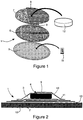
- the present invention as schematized by the Figures 1 and 2 consists of a patch 1 for an electronic tire module.
- the figure 1 is an exploded view of the configuration of a patch 1 for an electronic tire module consisting of different sheets 5, 6, 7 and 8. These sheets are arranged to delimit at least two separate compartments and provided with specific characteristics.
- This compartment 2 makes it possible to house an electronic module 11 of identification data.
- This electronic module 11 of identification data is inserted at the time of manufacture of the patch 1 and is housed permanently.
- This electronic module 11 of identification data is preferably an electronic identification module.
- the patch 1 provides a second compartment 3.
- the latter is provided against the compartment without opening, on the opposite side to the tire attachment face 10.
- the outer sheet 6 of the compartment 2 without opening is used to form a first wall.
- the other wall of the compartment is formed by two sheets 7 and 8 attached to the sheet 6.
- this compartment 3 has a resealable opening 4, to accommodate a module 12 in the compartment 3, removably.
- the compartment 3 with opening has an opening 4 constituted by a specific arrangement of the sheets 7 and 8: each sheet has a semi-circular profile, the two half-circles being arranged in opposition, with a superposition zone 9 substantially in the middle of the circle. The opening 4 created by this superposition is clearly visible at the figure 2 .
- This opening 4 can also be completed by security means such as a zipper, bands provided with hooks and loops ("Velcro”, registered trademark) or other means of closure.
- security means such as a zipper, bands provided with hooks and loops ("Velcro”, registered trademark) or other means of closure.
- the patch 1 is mechanically secured to the tire 10.
- the electronic modules 11 and 12 are respectively inserted into the compartments of the patch 1 so as to be movable therein.
- the fact that the electronic modules are mobile prevents them from being subjected to the mechanical stresses experienced by the patch 1.
- the modules are driven to a less mechanically stressed area. They are thus better protected and are less subject to deterioration thanks to this arrangement in compartments.
- a first embodiment consists of a patch 1 for electronic tire modules comprising at least two compartments 2 and 3, each of the compartments isolating electronic modules 11 and 12 with distinct functions.
- the electronic module 11 of identification data installed in the compartment 2 without opening is adapted to store identifier data of the corresponding tire.
- the electronic module 12 with complementary functions inserted into the compartment 3 opening is preferably a functional electronic module, the functions of which complete the functions of the electronic module 11 of identification data.
- This electronic module 12 with complementary functions may for example be part of a tire pressure monitoring system, and include a pressure sensor and possibly temperature.
- the module with complementary functions advantageously comprises a data exchange sub-module, adapted to transmit the acquired data to a reception and data management module, located on the vehicle or on an off-vehicle device. This sub-module allows on the other hand to receive or read the tire identification data of the module 11 of identification data. Since the two modules 11 and 12 are always very close to each other, communication errors are thus avoided.
- the electronic module 11 of identification data contains a tire identifier
- the fact that the module is permanently attached to a given tire makes it possible to guarantee that the identification data are perfectly reliable.
- the electronic module 12 with complementary functions can thus be removed or exchanged without risk.
- the possible new module receives the identification data of the module 11 of identification data, which has not changed.
- the compartments may be more numerous, to allow the insertion of a plurality of electronic modules with different functions.
- the patch 1 for the electronic module of the tire may have respective shapes and arrangements different from those illustrated in FIGS. Figures 1 and 2 .
- the sheets 5, 6, 7 and 8 constituting the patch 1 for the electronic module of the tire are made integral by gluing, welding, sewing and all other adapted way.
- the surface of the sheet 5 intended to cooperate with the wall 13 of the tire is provided with a compatible material for effecting attachment to this wall 13 by co-vulcanization.
- a compatible material for effecting attachment to this wall 13 by co-vulcanization.
- the use of an elastomeric composition to produce the sheet makes it possible to obtain a definitive, reliable and durable fixation.
- the opposite surface of the sheet 5 as well as the surfaces of the other sheets are non-sticky.
- the sheets 6, 7 and 8 are also made of extensible material. This type of material allows the patch to withstand the deformation constraints of the fixing wall and to be able to adapt to different types of contents.
Landscapes
- Engineering & Computer Science (AREA)
- Mechanical Engineering (AREA)
- Computer Networks & Wireless Communication (AREA)
- Measuring Fluid Pressure (AREA)
- Arrangements For Transmission Of Measured Signals (AREA)
- Tires In General (AREA)
Description
- La présente invention concerne un patch pour module électronique de pneumatique comportant un compartiment logeant un module électronique.
- De manière générale, deux solutions permettant de gérer des modules électroniques de pneumatique sont connues.
- La première solution consiste à intégrer un module électronique au pneumatique en le rendant définitivement fixe. Pour ce faire, le module électronique est mécaniquement et irréversiblement solidaire du pneumatique. Un tel agencement permet d'associer les données obtenues par ledit module à l'identifiant du pneumatique correspondant. Cette-solution empêche cependant le remplacement ou la modification du module électronique. Elle n'est donc pas compatible avec les systèmes électroniques prévus pour être amovibles.
- Le document
FR2870031 - La seconde solution consiste à prévoir un module électronique rapporté au pneumatique de façon amovible. Cette solution implique d'effectuer un appairage entre l'identifiant du pneumatique et le module électronique. Pour effectuer un tel appairage, on peut prévoir différentes démarches. Par exemple, l'appairage peut être effectué par une opération manuelle d'écriture de l'identifiant par un module communément appelé « RFID » ou par marquage dans la mémoire du module électronique. L'appairage peut aussi être réalisé par l'utilisation de portiques de synchronisation externes entre l'identifiant du pneumatique et le module électronique. L'appairage entre l'identifiant et le module électronique peut aussi être effectué via le véhicule. Enfin, l'appairage peut être réalisé par lecture directe de l'identifiant par le module électronique lui-même.
- Les solutions d'appairage manuelles ou utilisant des systèmes externes nécessitent un ré-appairage à chaque changement de module électronique ou de pneumatique. Dès lors, aucune garantie sur le bon appairage ne peut être apportée. De plus, l'appairage via le véhicule nécessite une infrastructure coûteuse et fortement intrusive au niveau du véhicule. Enfin, la solution de lecture directe de l'identifiant par un module électronique requiert une bonne communication entre les éléments concernés.
- Le document
DE102005023597 décrit un pneumatique de véhicule sur lequel est disposé, de manière simple, un module électronique de pneumatique. Pour ce faire, le module électronique est inséré dans une poche qui est fixée, à l'intérieur du pneumatique par un moyen de fixation à deux composants. - La demande
US2007/0175554 concerne un patch structuré afin de contenir un système électronique comprenant un capteur pour un pneumatique. La surface du patch est configurée afin d'être fixée sur le pneumatique. - Les documents suscités décrivent l'agencement de patchs destinés à loger des modules électroniques de pneumatiques. L'état de l'art fait référence à la manière dont sont associées des fonctions électroniques à des pneumatiques. Il en résulte que les fonctions électroniques pour pneumatiques sont gérées par un unique module électronique qui est soit définitivement implanté dans le pneumatique, soit apposé de façon amovible au pneumatique.
- Le document
DE1020080634469 - Le document
EP1384603 décrit un pneumatique dans lequel une antenne est intégrée dans la zone basse d'un des flancs. - Les solutions révélées par l'état de la technique présentent certaines imperfections quels que soient leurs agencements. Il subsiste par conséquent un besoin pour une solution efficace permettant de gérer différentes fonctions inhérentes aux modules électroniques de pneumatique, en relation avec des données d'identification.
- Pour pallier ces différents inconvénients, l'invention prévoit différents moyens techniques.
- Un premier objet de l'invention consiste à prévoir un moyen de fixation rapide et réversible d'un module électronique dans le pneumatique.
- Un autre objet de l'invention vise à prévoir un dispositif facilitant la maîtrise de la distance entre un module électronique comportant un identifiant du pneumatique et un éventuel autre module électronique, afin de faciliter la communication entre ces deux modules.
- Encore un objet de l'invention consiste à prévoir un dispositif permettant de combiner différents modules électroniques à fonctions complémentaires.
- Un autre objet de l'invention vise à prévoir un système de fixation permettant à un système de surveillance de pneumatique d'opérer sans risque d'erreurs concernant l'identification du pneumatique.
- Enfin un autre objet de l'invention consiste à prévoir un système de fixation permettant la mise en oeuvre d'un système de surveillance de pneumatique de façon à ce que l'historique de données de pression et / ou de température obtenu pour un pneumatique donné reste associé à ce pneumatique de manière rigoureuse, indépendamment de toute intervention ultérieure.
- Pour ce faire, l'invention prévoit un patch pour module électronique de pneumatique comportant un compartiment sans ouverture logeant un module électronique de données d'identification. Le patch comporte de plus un second compartiment destiné à loger un module électronique à fonctions complémentaires adapté pour recevoir les données d'identification du module de données d'identification, dans lequel le second compartiment comporte une ouverture refermable.
- Un tel agencement permet un appairage automatique entre les modules électroniques insérés dans des compartiments distincts et adjacents. Par exemple en cas de changement ou de retrait du module à fonctions complémentaires, lorsque le module initial ou un nouveau module est réinstallé, les données d'identifiant lui sont automatiquement transmises par le modules de données d'identification.
- Un tel agencement de compartiment à ouverture permet d'insérer un module électronique dans le compartiment à ouverture, de manière réversible. De plus, une telle architecture permet de procéder à diverses interventions sur le module électronique à fonctions complémentaires, telles que le remplacement, la maintenance, la réparation, ou encore le recyclage du module. En effet le module électronique inséré dans le compartiment du patch pourvu d'une ouverture peut être mis en place rapidement, et réversiblement. Enfin, une telle architecture permet de garantir une bonne interaction entre les modules électroniques, ces derniers étant insérés dans un unique patch pour modules électroniques de pneumatique.
- Selon un mode de réalisation avantageux, le module électronique de données d'identification du patch est conçu pour fournir des données d'identification du pneumatique correspondant.
- Selon un autre mode de réalisation, le module électronique à fonctions complémentaires du patch est conçu pour mettre en oeuvre des fonctions complémentaires aux fonctions du module électronique de données d'identification.
- Un tel agencement peut permettre de garantir un appairage fiable entre le module électronique de données d'identification et le module électronique à fonctions complémentaires. Egalement, et dans le cas où le module électronique de données d'identification comporte des données d'identification, une telle architecture permet d'associer sans risque d'erreur les mesures prises par le module électronique à fonctions complémentaires au bon pneumatique.
- Selon une variante avantageuse, les fonctions du module électronique à fonctions complémentaires sont comprises parmi la liste de fonctions suivantes :
- i) mesure de température,
- ii) mesure de pression,
- iii) mesure de cycles.
- Selon une variante avantageuse, le patch comprend une pluralité de feuilles en tissu bi-élastique.
- Egalement de manière avantageuse, les feuilles constituant le patch sont superposées de façon à former les compartiments.
- Une telle juxtaposition de feuilles présente l'avantage de pouvoir constituer autant de compartiments qu'il y a de feuilles de séparation.
- Encore de manière avantageuse, le patch comporte une feuille destinée à être en contact avec la paroi du pneumatique. Cette feuille sert de feuille de contact et est prévue de façon à adhérer à une surface constituée d'un mélange élastomère.
- Selon un mode de réalisation avantageux, le patch comporte une feuille disposée entre les deux compartiments et forme ainsi une feuille de séparation.
- Selon un autre mode de réalisation avantageux, le compartiment à ouverture du patch est formé d'un côté par la feuille de séparation et de l'autre côté par une ou plusieurs feuilles qui forment l'ouverture refermable.
- Egalement de manière avantageuse, la feuille de séparation du patch est constituée d'un tissu bi-élastique traité pour ne pas adhérer avec la face adjacente de la feuille de contact et la ou les faces adjacentes de la ou des feuilles formant ladite ouverture refermable.
- Encore de manière avantageuse, les feuilles formant l'ouverture refermable du patch sont traitées pour ne pas adhérer avec la face adjacente de la feuille de séparation.
- L'invention prévoit également un pneumatique comportant un patch tel que préalablement décrit fixé contre une paroi interne du pneumatique.
- Tous les détails de réalisation sont donnés dans la description qui suit, complétée par les
figures 1 et 2 présentées uniquement à des fins d'exemples non limitatifs, et dans lesquelles : - la
figure 1 est une vue éclatée des feuilles constitutives du patch pour modules électroniques de pneumatique ; - la
figure 2 est une vue en coupe de l'ensemble des éléments composant le patch selon l'invention. - La présente invention, telle que schématisée par les
figures 1 et 2 consiste en un patch 1 pour module électronique de pneumatique. - La
figure 1 est une vue éclatée de la configuration d'un patch 1 pour module électronique de pneumatique constitué de différentes feuilles 5, 6, 7 et 8. Ces feuilles sont disposées de façon à délimiter au moins deux compartiments distincts et pourvus de caractéristiques spécifiques. - Tout d'abord, les feuilles 5 et 6 sont fixées entre elles, en alignement l'une contre l'autre, afin de former un compartiment 2 sans ouverture. Ce compartiment 2 permet de loger un module électronique 11 de données d'identification. Ce module électronique 11 de données d'identification est inséré au moment de la fabrication du patch 1 et s'y trouve logé de manière définitive. Ce module électronique 11 de données d'identification est de manière préférentielle un module électronique d'identification.
- Selon l'invention, le patch 1 prévoit un second compartiment 3. Ce dernier est prévu contre le compartiment sans ouverture, du côté opposé à la face de fixation au pneumatique 10. Pour former ce compartiment 3, la feuille externe 6 du compartiment 2 sans ouverture est utilisée pour former une première paroi. L'autre paroi du compartiment est formée par deux feuilles 7 et 8 rapportées contre la feuille 6. Tel que montré aux
figures 1 et 2 , ce compartiment 3 dispose d'une ouverture 4 refermable, permettant de loger un module 12 dans le compartiment 3, de façon amovible. Dans l'exemple illustré, le compartiment 3 à ouverture comporte une ouverture 4 constituée par un agencement spécifique des feuilles 7 et 8 : chaque feuille a un profil semi-circulaire, les deux demi-cercles étant agencés en opposition, avec une zone de superposition 9 sensiblement au milieu du cercle. L'ouverture 4 créée par cette superposition est bien visible à lafigure 2 . - Cette ouverture 4 peut également être complétée par des moyens de sécurisation tels qu'une fermeture à glissière, des bandes pourvues de crochets et boucles (« Velcro », marque déposée) ou autre moyen de fermeture.
- Le patch 1 est mécaniquement solidaire du pneumatique 10. Les modules électroniques 11 et 12 sont respectivement insérés dans les compartiments du patch 1 de façon à être mobiles dans ces derniers. Le fait que les modules électroniques soient mobiles permet d'éviter qu'ils soient soumis aux contraintes mécaniques subies par le patch 1. En effet, en cas de contrainte subie par le pneumatique, du fait des déformations du pneumatique 10 et du patch 1, les modules sont entraînés vers une zone moins sollicitée mécaniquement. Ils sont ainsi mieux protégés et sont moins sujets à subir des détériorations grâce à cet agencement en compartiments.
- Selon l'invention, un premier mode de réalisation consiste en un patch 1 pour modules électroniques de pneumatique comportant au moins deux compartiments 2 et 3, chacun des compartiments isolant des modules électroniques 11 et 12 à fonctions distinctes.
- Selon ce premier mode de réalisation, le module électronique 11 de données d'identification installé dans le compartiment 2 sans ouverture est adapté pour mémoriser des données d'identifiant du pneumatique correspondant. Toujours selon ce premier mode de réalisation, le module électronique 12 à fonctions complémentaires inséré dans le compartiment 3 à ouverture est préférentiellement un module électronique fonctionnel, dont les fonctions complètent les fonctions du module électronique 11 de données d'identification. Ce module électronique 12 à fonctions complémentaires peut par exemple faire partie d'un système de surveillance de la pression des pneumatiques, et comporter un capteur de pression et éventuellement de température. Le module à fonctions complémentaires comprend avantageusement un sous-module d'échange de données, adapté pour transmettre les données acquises vers un module de réception et gestion des données, situé sur le véhicule ou sur un dispositif hors véhicule. Ce sous-module permet d'autre part de recevoir ou lire les données d'identification de pneumatique du module 11 de données d'identification. Les deux modules 11 et 12 étant toujours très près l'un de l'autre, les erreurs de communication sont ainsi évitées.
- Dans le cas où le module électronique 11 de données d'identification contient un identifiant de pneumatique, le fait que le module soit définitivement fixé à un pneumatique donné permet de garantir que les données d'identification sont parfaitement fiables. Le module électronique 12 à fonctions complémentaires peut ainsi être retiré, voire échangé, sans risque. L'éventuel nouveau module reçoit les données d'identification du module 11 de données d'identification, qui lui, n'a pas changé.
- Selon un autre mode de réalisation, les compartiments peuvent être plus nombreux, afin de permettre l'insertion d'une pluralité de modules électroniques dotés de fonctions différentes.
- Sans sortir du cadre de l'invention, le patch 1 pour module électronique de pneumatique, et par conséquent les compartiments 2 et 3 et les modules électroniques 11 et 12 insérés, peuvent avoir des formes et agencements respectifs différents de ceux illustrés aux
figures 1 et 2 . - Les feuilles 5, 6, 7 et 8 constitutives du patch 1 pour module électronique de pneumatique sont rendues solidaires par collage, soudure, couture et tout autre moyen adapté.
- La surface de la feuille 5 destinée à coopérer avec la paroi 13 du pneumatique est prévue avec un matériau compatible pour effectuer une fixation à cette paroi 13 par co-vulcanisation. L'utilisation d'une composition élastomère pour produire la feuille permet l'obtention d'une fixation définitive, fiable et durable. La surface opposée de la feuille 5 ainsi que les surfaces des autres feuilles sont non collantes. De plus, les feuilles 6, 7 et 8 sont également composées de matériau extensible. Ce type de matériau permet au patch de bien supporter les contraintes de déformation de la paroi de fixation et de pouvoir s'adapter à différents types de contenus.
- Les Figures et leurs descriptions faites ci-dessus illustrent l'invention plutôt qu'elles ne la limitent.
- Les signes de références dans les revendications n'ont aucun caractère limitatif. Les verbes "comprendre" et "comporter" n'excluent pas la présence d'autres éléments que ceux listés dans les revendications.
-
- 1
- Patch
- 2
- Compartiment sans ouverture
- 3
- Compartiment à ouverture
- 4
- Ouverture refermable
- 5
- Feuille de contact
- 6
- Feuille de séparation
- 7
- Feuille formant l'ouverture refermable
- 8
- Feuille formant l'ouverture refermable
- 10
- Pneumatique
- 11
- Module électronique de données d'identification
- 12
- Module électronique à fonctions complémentaires
- 13
- Paroi interne du pneumatique
Claims (12)
- Patch (1) pour module électronique de pneumatique comportant un compartiment (2) sans ouverture logeant un module électronique (11) de données d'identification, le patch comportant par ailleurs un second compartiment (3) destiné à loger un module électronique (12) à fonctions complémentaires adapté pour recevoir les données d'identification du module (11) de données d'identification, caractérisé en ce que le second compartiment (3) comporte une ouverture (4) refermable.
- Patch selon la revendication 1, dans lequel le module électronique (11) de données d'identification est conçu pour fournir des données d'identification du pneumatique (10) correspondant.
- Patch (1) selon l'une des revendications 1 à 2, dans lequel le module électronique (12) à fonctions complémentaires est conçu pour mettre en oeuvre des fonctions complémentaires aux fonctions du module électronique (11) de données d'identification.
- Patch selon la revendication 3, dans lequel les fonctions complémentaires du module électronique (12) à fonctions complémentaires sont comprises parmi la liste de fonctions suivante :- mesure de température ;- mesure de pression ;- mesure de cycles.
- Patch selon l'une des revendications précédentes, comprenant une pluralité de feuilles (5, 6, 7, 8) en tissu bi-élastique.
- Patch selon la revendication 5, dans lequel les feuilles (5, 6, 7, 8) sont superposées de façon à former les compartiments (2,3).
- Patch selon l'une des revendications 5 ou 6, dans lequel la feuille destinée à être en contact avec la paroi (13) du pneumatique sert de feuille de contact (5), cette feuille étant prévue de façon à adhérer à une surface constituée d'un mélange élastomère.
- Patch selon l'une des revendications 5 ou 6, dans lequel une des feuilles est disposée entre les deux compartiments (2, 3), et forme une feuille de séparation (6).
- Patch selon la revendication 8, dans lequel le compartiment à ouverture (3) est formé d'un côté par la feuille de séparation (6) et de l'autre côté par une ou plusieurs feuilles (7, 8) formant l'ouverture (4) refermable.
- Patch selon la revendication 9, dans lequel la feuille de séparation (6) est constituée d'un tissu bi-élastique traité pour ne pas adhérer avec la face adjacente de la feuille de contact (5) et la ou les faces adjacentes de la ou des feuilles (7, 8) formant ladite ouverture refermable.
- Patch selon l'une des revendications 9 ou 10, dans lequel les feuilles (7, 8) formant l'ouverture refermable sont traitées pour ne pas adhérer avec la face adjacente de la feuille de séparation (6).
- Pneumatique (10) comportant un patch (1) selon l'une des revendications 1 à 11, fixé contre une paroi interne (13) du pneumatique.
Applications Claiming Priority (2)
| Application Number | Priority Date | Filing Date | Title |
|---|---|---|---|
| FR1402854A FR3029845B1 (fr) | 2014-12-15 | 2014-12-15 | Patch pour module electronique de pneumatique |
| PCT/IB2015/002328 WO2016097836A1 (fr) | 2014-12-15 | 2015-12-13 | Patch pour module electronique de pneumatique |
Publications (3)
| Publication Number | Publication Date |
|---|---|
| EP3233539A1 EP3233539A1 (fr) | 2017-10-25 |
| EP3233539B1 true EP3233539B1 (fr) | 2018-12-05 |
| EP3233539B8 EP3233539B8 (fr) | 2019-02-20 |
Family
ID=52737137
Family Applications (1)
| Application Number | Title | Priority Date | Filing Date |
|---|---|---|---|
| EP15825808.7A Active EP3233539B8 (fr) | 2014-12-15 | 2015-12-13 | Patch pour module electronique de pneumatique |
Country Status (5)
| Country | Link |
|---|---|
| US (1) | US10414217B2 (fr) |
| EP (1) | EP3233539B8 (fr) |
| CN (1) | CN107206854B (fr) |
| FR (1) | FR3029845B1 (fr) |
| WO (1) | WO2016097836A1 (fr) |
Families Citing this family (3)
| Publication number | Priority date | Publication date | Assignee | Title |
|---|---|---|---|---|
| GB2545693B (en) | 2015-12-22 | 2020-05-20 | Schrader Electronics Ltd | Advanced tire monitoring system |
| BR112022002165A2 (pt) * | 2019-08-05 | 2022-06-07 | Bridgestone Americas Tire Operations Llc | Aparelho |
| US20220297484A1 (en) * | 2019-08-05 | 2022-09-22 | Bridgestone Americas Tire Operations, Llc | Tire electronics assembly |
Family Cites Families (23)
| Publication number | Priority date | Publication date | Assignee | Title |
|---|---|---|---|---|
| US5500065A (en) * | 1994-06-03 | 1996-03-19 | Bridgestone/Firestone, Inc. | Method for embedding a monitoring device within a tire during manufacture |
| US6030478A (en) * | 1998-02-10 | 2000-02-29 | Bridgestone/Firestone, Inc. | Method and apparatus for removably inserting an electric tire tag into a tire |
| AU5668999A (en) * | 1998-08-03 | 2000-02-28 | Goodyear Tire And Rubber Company, The | Antennas for transponders in pneumatic tires |
| FR2823148A1 (fr) * | 2001-04-09 | 2002-10-11 | Michelin Soc Tech | Dispositif de fixation d'un module electronique de surveillance sur un pneumatique |
| US6809700B2 (en) * | 2002-07-24 | 2004-10-26 | The Goodyear Tire & Rubber Company | Tag housing and assembly method for annular apparatus |
| GB2392889A (en) * | 2002-09-16 | 2004-03-17 | Smartronics Ltd | Tyre with electronic tag |
| US20050126668A1 (en) * | 2003-12-16 | 2005-06-16 | Pierre Fornerod | Post patch for mounting devices inside tires |
| FR2870031B1 (fr) | 2004-05-04 | 2006-06-16 | Michelin Soc Tech | Procede perfectionne de surveillance d'un pneumatique, pneumatique pour sa mise en oeuvre, et application |
| JP2006015884A (ja) * | 2004-07-02 | 2006-01-19 | Yokohama Rubber Co Ltd:The | タイヤ情報送信装置、タイヤ情報取得システムおよびタイヤ・ホイール組立体 |
| CN101155702B (zh) * | 2005-03-31 | 2010-12-15 | 倍耐力轮胎股份公司 | 具有检测至少一个特性参数的装置的轮胎及其制造方法 |
| DE102005023597A1 (de) | 2005-05-18 | 2006-11-23 | Continental Aktiengesellschaft | Fahrzeugreifen |
| US7770444B2 (en) | 2005-12-13 | 2010-08-10 | Michelin Recherche Et Technique S.A. | Patch for fixing an electronic system to a tire |
| FR2899149B1 (fr) * | 2006-04-04 | 2008-05-30 | Michelin Soc Tech | Dispositif de fixation d'un module sur la paroi interne d'un pneumatique |
| DE102008063469A1 (de) * | 2008-12-17 | 2010-01-28 | Continental Automotive Gmbh | Reifenmodulbaugruppe mit Hohlräumen |
| EP2483880B1 (fr) * | 2009-09-30 | 2014-03-26 | MICHELIN Recherche et Technique S.A. | Appareil et procédé destinés à la mesure de la température d'un pneumatique |
| FR2950691B1 (fr) * | 2009-09-30 | 2012-05-04 | Michelin Soc Tech | Organe de mesure de pression etanche |
| DE102012216577B4 (de) * | 2012-09-17 | 2023-04-20 | Bayerische Motoren Werke Aktiengesellschaft | Speichern von Reifeninformation in einem Reifensensor |
| US20140261944A1 (en) * | 2013-03-15 | 2014-09-18 | The Goodyear Tire & Rubber Company | Encasing for releasably containing a device and tire containing such encasing or encased device |
| FR3013870B1 (fr) | 2013-11-27 | 2016-01-01 | Michelin & Cie | Systeme de lecture dynamique de donnees de transpondeurs |
| FR3013907B1 (fr) | 2013-11-27 | 2016-01-01 | Michelin & Cie | Systeme de lecture dynamique de donnees de transpondeurs |
| FR3018737B1 (fr) * | 2014-03-21 | 2017-05-19 | Michelin & Cie | Patch de support¨pour pneumatique |
| DE102014205921A1 (de) * | 2014-03-31 | 2015-10-01 | Aktiebolaget Skf | Modul |
| FR3030374B1 (fr) * | 2014-12-17 | 2017-01-13 | Michelin & Cie | Procede de detection et d'alerte de l'etat de sous-gonflage d'un pneumatique |
-
2014
- 2014-12-15 FR FR1402854A patent/FR3029845B1/fr not_active Expired - Fee Related
-
2015
- 2015-12-13 WO PCT/IB2015/002328 patent/WO2016097836A1/fr active Application Filing
- 2015-12-13 EP EP15825808.7A patent/EP3233539B8/fr active Active
- 2015-12-13 CN CN201580075613.4A patent/CN107206854B/zh active Active
- 2015-12-13 US US15/536,375 patent/US10414217B2/en active Active
Non-Patent Citations (1)
| Title |
|---|
| None * |
Also Published As
| Publication number | Publication date |
|---|---|
| FR3029845A1 (fr) | 2016-06-17 |
| EP3233539B8 (fr) | 2019-02-20 |
| CN107206854A (zh) | 2017-09-26 |
| WO2016097836A1 (fr) | 2016-06-23 |
| EP3233539A1 (fr) | 2017-10-25 |
| CN107206854B (zh) | 2019-08-09 |
| US20170341475A1 (en) | 2017-11-30 |
| FR3029845B1 (fr) | 2017-08-11 |
| US10414217B2 (en) | 2019-09-17 |
Similar Documents
| Publication | Publication Date | Title |
|---|---|---|
| EP3233539B1 (fr) | Patch pour module electronique de pneumatique | |
| EP3119619B1 (fr) | Patch de support pour pneumatique | |
| EP3457002B1 (fr) | Dispositif d'étanchéité pour organe de dialogue homme-machine | |
| WO2012019956A1 (fr) | Dispositif d'identification d'un animal et dispositif de fabrication correspondant | |
| EP1046968B1 (fr) | Fixation réciproque d'une glace, d'un cadran et d'un cercle d'encageage pour une pièce d'horlogerie | |
| EP3756501B1 (fr) | Dispositif de fixation d'un bracelet | |
| WO2013013789A1 (fr) | Unité électronique de mesure de paramètres de fonctionnement d'une roue de véhicule, comprenant un boîtier électronique et une valve de gonflage | |
| EP3088970A1 (fr) | Montre destinée à être montée sur un support amovible | |
| EP3574377A1 (fr) | Boîtier de montre comportant une capsule maintenue dans une carrure par une lunette arrière | |
| FR3009228A1 (fr) | Moule pour pneumatique comportant un insert annulaire en plusieurs parties | |
| EP2685326B1 (fr) | Cadran de montre fixé sur une platine | |
| EP3428057B1 (fr) | Gâche de serrure et aéronef comportant une telle gâche | |
| FR2907318A1 (fr) | Systeme de talon interchangeable, procede de fabrication du talon et chaussure associe. | |
| EP2960406A1 (fr) | Dispositif d'ouverture et de fermeture d'un article notamment de maroquinerie et article comportant un tel dispositif | |
| EP3213804A1 (fr) | Dispositif de support pour filtre a gasoil d'un vehicule automobile | |
| WO2003034815A1 (fr) | Perfectionnement pour dispositif d'identification | |
| FR3024343A1 (fr) | Systeme de protection pour dispositif de communication mobile et procede d'installation de ce systeme de protection | |
| EP2132983A2 (fr) | Bracelet d'identification d'un ensemble d'éléments | |
| EP3167770B1 (fr) | Dispositif sécurisé de présentation d'objets | |
| FR3069590A1 (fr) | Un systeme de cage ecrou comportant une cage ecrou et un support sur lequel la cage est destinee a etre montee | |
| FR3066283B1 (fr) | Dispositif de prise de vues d'un objet pour en reconstituer l'enveloppe en 3d | |
| US20160273594A1 (en) | One-Way Transmission Module | |
| EP3050457B1 (fr) | Dispositif de protection et de decoration | |
| EP2644246A1 (fr) | Filtre à air muni de moyens d'assemblage de ses élements filtrants | |
| EP2433271B1 (fr) | Lien d'identification avec deux verrous |
Legal Events
| Date | Code | Title | Description |
|---|---|---|---|
| PUAI | Public reference made under article 153(3) epc to a published international application that has entered the european phase |
Free format text: ORIGINAL CODE: 0009012 |
|
| 17P | Request for examination filed |
Effective date: 20170717 |
|
| AK | Designated contracting states |
Kind code of ref document: A1 Designated state(s): AL AT BE BG CH CY CZ DE DK EE ES FI FR GB GR HR HU IE IS IT LI LT LU LV MC MK MT NL NO PL PT RO RS SE SI SK SM TR |
|
| AX | Request for extension of the european patent |
Extension state: BA ME |
|
| DAV | Request for validation of the european patent (deleted) | ||
| DAX | Request for extension of the european patent (deleted) | ||
| GRAP | Despatch of communication of intention to grant a patent |
Free format text: ORIGINAL CODE: EPIDOSNIGR1 |
|
| INTG | Intention to grant announced |
Effective date: 20180711 |
|
| GRAS | Grant fee paid |
Free format text: ORIGINAL CODE: EPIDOSNIGR3 |
|
| RAP1 | Party data changed (applicant data changed or rights of an application transferred) |
Owner name: MICHELIN RECHERCHE ET TECHNIQUE S.A. Owner name: COMPAGNIE GENERALE DES ETABLISSEMENTS MICHELIN |
|
| GRAA | (expected) grant |
Free format text: ORIGINAL CODE: 0009210 |
|
| STAA | Information on the status of an ep patent application or granted ep patent |
Free format text: STATUS: THE PATENT HAS BEEN GRANTED |
|
| GRAT | Correction requested after decision to grant or after decision to maintain patent in amended form |
Free format text: ORIGINAL CODE: EPIDOSNCDEC |
|
| AK | Designated contracting states |
Kind code of ref document: B1 Designated state(s): AL AT BE BG CH CY CZ DE DK EE ES FI FR GB GR HR HU IE IS IT LI LT LU LV MC MK MT NL NO PL PT RO RS SE SI SK SM TR |
|
| RAP1 | Party data changed (applicant data changed or rights of an application transferred) |
Owner name: MICHELIN RECHERCHE ET TECHNIQUE S.A. Owner name: COMPAGNIE GENERALE DES ETABLISSEMENTS MICHELIN |
|
| REG | Reference to a national code |
Ref country code: GB Ref legal event code: FG4D Free format text: NOT ENGLISH |
|
| REG | Reference to a national code |
Ref country code: CH Ref legal event code: EP |
|
| REG | Reference to a national code |
Ref country code: AT Ref legal event code: REF Ref document number: 1072557 Country of ref document: AT Kind code of ref document: T Effective date: 20181215 |
|
| REG | Reference to a national code |
Ref country code: IE Ref legal event code: FG4D Free format text: LANGUAGE OF EP DOCUMENT: FRENCH |
|
| REG | Reference to a national code |
Ref country code: DE Ref legal event code: R096 Ref document number: 602015021074 Country of ref document: DE |
|
| RAP2 | Party data changed (patent owner data changed or rights of a patent transferred) |
Owner name: COMPAGNIE GENERALE DES ETABLISSEMENTS MICHELIN |
|
| REG | Reference to a national code |
Ref country code: CH Ref legal event code: PK Free format text: RECTIFICATION B8 |
|
| REG | Reference to a national code |
Ref country code: NL Ref legal event code: FP |
|
| REG | Reference to a national code |
Ref country code: AT Ref legal event code: MK05 Ref document number: 1072557 Country of ref document: AT Kind code of ref document: T Effective date: 20181205 |
|
| REG | Reference to a national code |
Ref country code: LT Ref legal event code: MG4D |
|
| PG25 | Lapsed in a contracting state [announced via postgrant information from national office to epo] |
Ref country code: LV Free format text: LAPSE BECAUSE OF FAILURE TO SUBMIT A TRANSLATION OF THE DESCRIPTION OR TO PAY THE FEE WITHIN THE PRESCRIBED TIME-LIMIT Effective date: 20181205 Ref country code: AT Free format text: LAPSE BECAUSE OF FAILURE TO SUBMIT A TRANSLATION OF THE DESCRIPTION OR TO PAY THE FEE WITHIN THE PRESCRIBED TIME-LIMIT Effective date: 20181205 Ref country code: FI Free format text: LAPSE BECAUSE OF FAILURE TO SUBMIT A TRANSLATION OF THE DESCRIPTION OR TO PAY THE FEE WITHIN THE PRESCRIBED TIME-LIMIT Effective date: 20181205 Ref country code: NO Free format text: LAPSE BECAUSE OF FAILURE TO SUBMIT A TRANSLATION OF THE DESCRIPTION OR TO PAY THE FEE WITHIN THE PRESCRIBED TIME-LIMIT Effective date: 20190305 Ref country code: HR Free format text: LAPSE BECAUSE OF FAILURE TO SUBMIT A TRANSLATION OF THE DESCRIPTION OR TO PAY THE FEE WITHIN THE PRESCRIBED TIME-LIMIT Effective date: 20181205 Ref country code: BG Free format text: LAPSE BECAUSE OF FAILURE TO SUBMIT A TRANSLATION OF THE DESCRIPTION OR TO PAY THE FEE WITHIN THE PRESCRIBED TIME-LIMIT Effective date: 20190305 Ref country code: LT Free format text: LAPSE BECAUSE OF FAILURE TO SUBMIT A TRANSLATION OF THE DESCRIPTION OR TO PAY THE FEE WITHIN THE PRESCRIBED TIME-LIMIT Effective date: 20181205 Ref country code: ES Free format text: LAPSE BECAUSE OF FAILURE TO SUBMIT A TRANSLATION OF THE DESCRIPTION OR TO PAY THE FEE WITHIN THE PRESCRIBED TIME-LIMIT Effective date: 20181205 |
|
| PG25 | Lapsed in a contracting state [announced via postgrant information from national office to epo] |
Ref country code: RS Free format text: LAPSE BECAUSE OF FAILURE TO SUBMIT A TRANSLATION OF THE DESCRIPTION OR TO PAY THE FEE WITHIN THE PRESCRIBED TIME-LIMIT Effective date: 20181205 Ref country code: SE Free format text: LAPSE BECAUSE OF FAILURE TO SUBMIT A TRANSLATION OF THE DESCRIPTION OR TO PAY THE FEE WITHIN THE PRESCRIBED TIME-LIMIT Effective date: 20181205 Ref country code: GR Free format text: LAPSE BECAUSE OF FAILURE TO SUBMIT A TRANSLATION OF THE DESCRIPTION OR TO PAY THE FEE WITHIN THE PRESCRIBED TIME-LIMIT Effective date: 20190306 Ref country code: AL Free format text: LAPSE BECAUSE OF FAILURE TO SUBMIT A TRANSLATION OF THE DESCRIPTION OR TO PAY THE FEE WITHIN THE PRESCRIBED TIME-LIMIT Effective date: 20181205 |
|
| PG25 | Lapsed in a contracting state [announced via postgrant information from national office to epo] |
Ref country code: PL Free format text: LAPSE BECAUSE OF FAILURE TO SUBMIT A TRANSLATION OF THE DESCRIPTION OR TO PAY THE FEE WITHIN THE PRESCRIBED TIME-LIMIT Effective date: 20181205 Ref country code: CZ Free format text: LAPSE BECAUSE OF FAILURE TO SUBMIT A TRANSLATION OF THE DESCRIPTION OR TO PAY THE FEE WITHIN THE PRESCRIBED TIME-LIMIT Effective date: 20181205 Ref country code: PT Free format text: LAPSE BECAUSE OF FAILURE TO SUBMIT A TRANSLATION OF THE DESCRIPTION OR TO PAY THE FEE WITHIN THE PRESCRIBED TIME-LIMIT Effective date: 20190405 Ref country code: IT Free format text: LAPSE BECAUSE OF FAILURE TO SUBMIT A TRANSLATION OF THE DESCRIPTION OR TO PAY THE FEE WITHIN THE PRESCRIBED TIME-LIMIT Effective date: 20181205 |
|
| REG | Reference to a national code |
Ref country code: CH Ref legal event code: PL |
|
| PG25 | Lapsed in a contracting state [announced via postgrant information from national office to epo] |
Ref country code: RO Free format text: LAPSE BECAUSE OF FAILURE TO SUBMIT A TRANSLATION OF THE DESCRIPTION OR TO PAY THE FEE WITHIN THE PRESCRIBED TIME-LIMIT Effective date: 20181205 Ref country code: IS Free format text: LAPSE BECAUSE OF FAILURE TO SUBMIT A TRANSLATION OF THE DESCRIPTION OR TO PAY THE FEE WITHIN THE PRESCRIBED TIME-LIMIT Effective date: 20190405 Ref country code: SK Free format text: LAPSE BECAUSE OF FAILURE TO SUBMIT A TRANSLATION OF THE DESCRIPTION OR TO PAY THE FEE WITHIN THE PRESCRIBED TIME-LIMIT Effective date: 20181205 Ref country code: LU Free format text: LAPSE BECAUSE OF NON-PAYMENT OF DUE FEES Effective date: 20181213 Ref country code: EE Free format text: LAPSE BECAUSE OF FAILURE TO SUBMIT A TRANSLATION OF THE DESCRIPTION OR TO PAY THE FEE WITHIN THE PRESCRIBED TIME-LIMIT Effective date: 20181205 Ref country code: SM Free format text: LAPSE BECAUSE OF FAILURE TO SUBMIT A TRANSLATION OF THE DESCRIPTION OR TO PAY THE FEE WITHIN THE PRESCRIBED TIME-LIMIT Effective date: 20181205 |
|
| REG | Reference to a national code |
Ref country code: DE Ref legal event code: R097 Ref document number: 602015021074 Country of ref document: DE |
|
| REG | Reference to a national code |
Ref country code: IE Ref legal event code: MM4A |
|
| REG | Reference to a national code |
Ref country code: BE Ref legal event code: MM Effective date: 20181231 |
|
| PLBE | No opposition filed within time limit |
Free format text: ORIGINAL CODE: 0009261 |
|
| STAA | Information on the status of an ep patent application or granted ep patent |
Free format text: STATUS: NO OPPOSITION FILED WITHIN TIME LIMIT |
|
| PG25 | Lapsed in a contracting state [announced via postgrant information from national office to epo] |
Ref country code: SI Free format text: LAPSE BECAUSE OF FAILURE TO SUBMIT A TRANSLATION OF THE DESCRIPTION OR TO PAY THE FEE WITHIN THE PRESCRIBED TIME-LIMIT Effective date: 20181205 Ref country code: MC Free format text: LAPSE BECAUSE OF FAILURE TO SUBMIT A TRANSLATION OF THE DESCRIPTION OR TO PAY THE FEE WITHIN THE PRESCRIBED TIME-LIMIT Effective date: 20181205 Ref country code: DK Free format text: LAPSE BECAUSE OF FAILURE TO SUBMIT A TRANSLATION OF THE DESCRIPTION OR TO PAY THE FEE WITHIN THE PRESCRIBED TIME-LIMIT Effective date: 20181205 Ref country code: IE Free format text: LAPSE BECAUSE OF NON-PAYMENT OF DUE FEES Effective date: 20181213 |
|
| 26N | No opposition filed |
Effective date: 20190906 |
|
| PG25 | Lapsed in a contracting state [announced via postgrant information from national office to epo] |
Ref country code: BE Free format text: LAPSE BECAUSE OF NON-PAYMENT OF DUE FEES Effective date: 20181231 |
|
| PG25 | Lapsed in a contracting state [announced via postgrant information from national office to epo] |
Ref country code: LI Free format text: LAPSE BECAUSE OF NON-PAYMENT OF DUE FEES Effective date: 20181231 Ref country code: CH Free format text: LAPSE BECAUSE OF NON-PAYMENT OF DUE FEES Effective date: 20181231 |
|
| PG25 | Lapsed in a contracting state [announced via postgrant information from national office to epo] |
Ref country code: MT Free format text: LAPSE BECAUSE OF FAILURE TO SUBMIT A TRANSLATION OF THE DESCRIPTION OR TO PAY THE FEE WITHIN THE PRESCRIBED TIME-LIMIT Effective date: 20181205 |
|
| PG25 | Lapsed in a contracting state [announced via postgrant information from national office to epo] |
Ref country code: TR Free format text: LAPSE BECAUSE OF FAILURE TO SUBMIT A TRANSLATION OF THE DESCRIPTION OR TO PAY THE FEE WITHIN THE PRESCRIBED TIME-LIMIT Effective date: 20181205 |
|
| PG25 | Lapsed in a contracting state [announced via postgrant information from national office to epo] |
Ref country code: MK Free format text: LAPSE BECAUSE OF NON-PAYMENT OF DUE FEES Effective date: 20181205 Ref country code: CY Free format text: LAPSE BECAUSE OF FAILURE TO SUBMIT A TRANSLATION OF THE DESCRIPTION OR TO PAY THE FEE WITHIN THE PRESCRIBED TIME-LIMIT Effective date: 20181205 Ref country code: HU Free format text: LAPSE BECAUSE OF FAILURE TO SUBMIT A TRANSLATION OF THE DESCRIPTION OR TO PAY THE FEE WITHIN THE PRESCRIBED TIME-LIMIT; INVALID AB INITIO Effective date: 20151213 |
|
| GBPC | Gb: european patent ceased through non-payment of renewal fee |
Effective date: 20191213 |
|
| PG25 | Lapsed in a contracting state [announced via postgrant information from national office to epo] |
Ref country code: GB Free format text: LAPSE BECAUSE OF NON-PAYMENT OF DUE FEES Effective date: 20191213 |
|
| PGFP | Annual fee paid to national office [announced via postgrant information from national office to epo] |
Ref country code: NL Payment date: 20231220 Year of fee payment: 9 Ref country code: FR Payment date: 20231221 Year of fee payment: 9 Ref country code: DE Payment date: 20231214 Year of fee payment: 9 |