EP3232959B1 - Vis à os - Google Patents
Vis à os Download PDFInfo
- Publication number
- EP3232959B1 EP3232959B1 EP15871023.6A EP15871023A EP3232959B1 EP 3232959 B1 EP3232959 B1 EP 3232959B1 EP 15871023 A EP15871023 A EP 15871023A EP 3232959 B1 EP3232959 B1 EP 3232959B1
- Authority
- EP
- European Patent Office
- Prior art keywords
- bone
- screw
- pedicle
- threaded
- sleeve
- Prior art date
- Legal status (The legal status is an assumption and is not a legal conclusion. Google has not performed a legal analysis and makes no representation as to the accuracy of the status listed.)
- Active
Links
- 210000000988 bone and bone Anatomy 0.000 title claims description 117
- 238000004873 anchoring Methods 0.000 claims description 10
- 239000000463 material Substances 0.000 description 26
- 238000003780 insertion Methods 0.000 description 14
- 230000037431 insertion Effects 0.000 description 14
- 239000000523 sample Substances 0.000 description 9
- 238000002513 implantation Methods 0.000 description 7
- 230000001965 increasing effect Effects 0.000 description 7
- 238000000034 method Methods 0.000 description 7
- 208000007103 Spondylolisthesis Diseases 0.000 description 4
- 230000004927 fusion Effects 0.000 description 4
- 230000033001 locomotion Effects 0.000 description 4
- 230000006641 stabilisation Effects 0.000 description 4
- 238000011105 stabilization Methods 0.000 description 4
- 238000011282 treatment Methods 0.000 description 3
- 208000001132 Osteoporosis Diseases 0.000 description 2
- RTAQQCXQSZGOHL-UHFFFAOYSA-N Titanium Chemical compound [Ti] RTAQQCXQSZGOHL-UHFFFAOYSA-N 0.000 description 2
- 229910045601 alloy Inorganic materials 0.000 description 2
- 239000000956 alloy Substances 0.000 description 2
- 208000037873 arthrodesis Diseases 0.000 description 2
- 230000001054 cortical effect Effects 0.000 description 2
- 230000006837 decompression Effects 0.000 description 2
- 238000013461 design Methods 0.000 description 2
- 230000002708 enhancing effect Effects 0.000 description 2
- 229910052500 inorganic mineral Inorganic materials 0.000 description 2
- 229910001092 metal group alloy Inorganic materials 0.000 description 2
- 239000011707 mineral Substances 0.000 description 2
- 238000012986 modification Methods 0.000 description 2
- 230000004048 modification Effects 0.000 description 2
- 229910001000 nickel titanium Inorganic materials 0.000 description 2
- 230000001737 promoting effect Effects 0.000 description 2
- 239000007787 solid Substances 0.000 description 2
- 230000000087 stabilizing effect Effects 0.000 description 2
- 239000010935 stainless steel Substances 0.000 description 2
- 229910001220 stainless steel Inorganic materials 0.000 description 2
- 239000000126 substance Substances 0.000 description 2
- 229910052719 titanium Inorganic materials 0.000 description 2
- 239000010936 titanium Substances 0.000 description 2
- 229920000049 Carbon (fiber) Polymers 0.000 description 1
- 229910000684 Cobalt-chrome Inorganic materials 0.000 description 1
- 206010061246 Intervertebral disc degeneration Diseases 0.000 description 1
- 241000124008 Mammalia Species 0.000 description 1
- 239000004696 Poly ether ether ketone Substances 0.000 description 1
- 208000002607 Pseudarthrosis Diseases 0.000 description 1
- 206010058907 Spinal deformity Diseases 0.000 description 1
- 208000020307 Spinal disease Diseases 0.000 description 1
- 208000020339 Spinal injury Diseases 0.000 description 1
- 229910001069 Ti alloy Inorganic materials 0.000 description 1
- HZEWFHLRYVTOIW-UHFFFAOYSA-N [Ti].[Ni] Chemical compound [Ti].[Ni] HZEWFHLRYVTOIW-UHFFFAOYSA-N 0.000 description 1
- 238000004458 analytical method Methods 0.000 description 1
- 210000003484 anatomy Anatomy 0.000 description 1
- 238000005452 bending Methods 0.000 description 1
- 239000002639 bone cement Substances 0.000 description 1
- 239000004917 carbon fiber Substances 0.000 description 1
- 239000010952 cobalt-chrome Substances 0.000 description 1
- 208000018180 degenerative disc disease Diseases 0.000 description 1
- 230000003412 degenerative effect Effects 0.000 description 1
- 230000001419 dependent effect Effects 0.000 description 1
- 229940079593 drug Drugs 0.000 description 1
- 239000003814 drug Substances 0.000 description 1
- 210000002082 fibula Anatomy 0.000 description 1
- 230000035876 healing Effects 0.000 description 1
- 229910052588 hydroxylapatite Inorganic materials 0.000 description 1
- 230000006872 improvement Effects 0.000 description 1
- 208000021600 intervertebral disc degenerative disease Diseases 0.000 description 1
- 230000007246 mechanism Effects 0.000 description 1
- 229910052751 metal Inorganic materials 0.000 description 1
- 239000002184 metal Substances 0.000 description 1
- 150000002739 metals Chemical class 0.000 description 1
- VNWKTOKETHGBQD-UHFFFAOYSA-N methane Chemical compound C VNWKTOKETHGBQD-UHFFFAOYSA-N 0.000 description 1
- 238000010883 osseointegration Methods 0.000 description 1
- XYJRXVWERLGGKC-UHFFFAOYSA-D pentacalcium;hydroxide;triphosphate Chemical compound [OH-].[Ca+2].[Ca+2].[Ca+2].[Ca+2].[Ca+2].[O-]P([O-])([O-])=O.[O-]P([O-])([O-])=O.[O-]P([O-])([O-])=O XYJRXVWERLGGKC-UHFFFAOYSA-D 0.000 description 1
- 239000004033 plastic Substances 0.000 description 1
- 230000008439 repair process Effects 0.000 description 1
- 238000010079 rubber tapping Methods 0.000 description 1
- 206010041569 spinal fracture Diseases 0.000 description 1
- 238000012360 testing method Methods 0.000 description 1
- 229920001169 thermoplastic Polymers 0.000 description 1
- 210000002303 tibia Anatomy 0.000 description 1
- 210000000623 ulna Anatomy 0.000 description 1
- 210000000689 upper leg Anatomy 0.000 description 1
Images


Classifications
-
- A—HUMAN NECESSITIES
- A61—MEDICAL OR VETERINARY SCIENCE; HYGIENE
- A61B—DIAGNOSIS; SURGERY; IDENTIFICATION
- A61B17/00—Surgical instruments, devices or methods, e.g. tourniquets
- A61B17/56—Surgical instruments or methods for treatment of bones or joints; Devices specially adapted therefor
- A61B17/58—Surgical instruments or methods for treatment of bones or joints; Devices specially adapted therefor for osteosynthesis, e.g. bone plates, screws, setting implements or the like
- A61B17/68—Internal fixation devices, including fasteners and spinal fixators, even if a part thereof projects from the skin
- A61B17/70—Spinal positioners or stabilisers ; Bone stabilisers comprising fluid filler in an implant
- A61B17/7001—Screws or hooks combined with longitudinal elements which do not contact vertebrae
- A61B17/7032—Screws or hooks with U-shaped head or back through which longitudinal rods pass
-
- A—HUMAN NECESSITIES
- A61—MEDICAL OR VETERINARY SCIENCE; HYGIENE
- A61B—DIAGNOSIS; SURGERY; IDENTIFICATION
- A61B17/00—Surgical instruments, devices or methods, e.g. tourniquets
- A61B17/16—Bone cutting, breaking or removal means other than saws, e.g. Osteoclasts; Drills or chisels for bones; Trepans
- A61B17/1604—Chisels; Rongeurs; Punches; Stamps
-
- A—HUMAN NECESSITIES
- A61—MEDICAL OR VETERINARY SCIENCE; HYGIENE
- A61B—DIAGNOSIS; SURGERY; IDENTIFICATION
- A61B17/00—Surgical instruments, devices or methods, e.g. tourniquets
- A61B17/16—Bone cutting, breaking or removal means other than saws, e.g. Osteoclasts; Drills or chisels for bones; Trepans
- A61B17/1642—Bone cutting, breaking or removal means other than saws, e.g. Osteoclasts; Drills or chisels for bones; Trepans for producing a curved bore
-
- A—HUMAN NECESSITIES
- A61—MEDICAL OR VETERINARY SCIENCE; HYGIENE
- A61B—DIAGNOSIS; SURGERY; IDENTIFICATION
- A61B17/00—Surgical instruments, devices or methods, e.g. tourniquets
- A61B17/16—Bone cutting, breaking or removal means other than saws, e.g. Osteoclasts; Drills or chisels for bones; Trepans
- A61B17/1662—Bone cutting, breaking or removal means other than saws, e.g. Osteoclasts; Drills or chisels for bones; Trepans for particular parts of the body
- A61B17/1671—Bone cutting, breaking or removal means other than saws, e.g. Osteoclasts; Drills or chisels for bones; Trepans for particular parts of the body for the spine
-
- A—HUMAN NECESSITIES
- A61—MEDICAL OR VETERINARY SCIENCE; HYGIENE
- A61B—DIAGNOSIS; SURGERY; IDENTIFICATION
- A61B17/00—Surgical instruments, devices or methods, e.g. tourniquets
- A61B17/56—Surgical instruments or methods for treatment of bones or joints; Devices specially adapted therefor
- A61B17/58—Surgical instruments or methods for treatment of bones or joints; Devices specially adapted therefor for osteosynthesis, e.g. bone plates, screws, setting implements or the like
- A61B17/68—Internal fixation devices, including fasteners and spinal fixators, even if a part thereof projects from the skin
- A61B17/70—Spinal positioners or stabilisers ; Bone stabilisers comprising fluid filler in an implant
- A61B17/7074—Tools specially adapted for spinal fixation operations other than for bone removal or filler handling
- A61B17/7076—Tools specially adapted for spinal fixation operations other than for bone removal or filler handling for driving, positioning or assembling spinal clamps or bone anchors specially adapted for spinal fixation
- A61B17/7082—Tools specially adapted for spinal fixation operations other than for bone removal or filler handling for driving, positioning or assembling spinal clamps or bone anchors specially adapted for spinal fixation for driving, i.e. rotating, screws or screw parts specially adapted for spinal fixation, e.g. for driving polyaxial or tulip-headed screws
-
- A—HUMAN NECESSITIES
- A61—MEDICAL OR VETERINARY SCIENCE; HYGIENE
- A61B—DIAGNOSIS; SURGERY; IDENTIFICATION
- A61B17/00—Surgical instruments, devices or methods, e.g. tourniquets
- A61B17/56—Surgical instruments or methods for treatment of bones or joints; Devices specially adapted therefor
- A61B17/58—Surgical instruments or methods for treatment of bones or joints; Devices specially adapted therefor for osteosynthesis, e.g. bone plates, screws, setting implements or the like
- A61B17/68—Internal fixation devices, including fasteners and spinal fixators, even if a part thereof projects from the skin
- A61B17/84—Fasteners therefor or fasteners being internal fixation devices
- A61B17/86—Pins or screws or threaded wires; nuts therefor
- A61B17/8625—Shanks, i.e. parts contacting bone tissue
- A61B17/8635—Tips of screws
-
- A—HUMAN NECESSITIES
- A61—MEDICAL OR VETERINARY SCIENCE; HYGIENE
- A61B—DIAGNOSIS; SURGERY; IDENTIFICATION
- A61B17/00—Surgical instruments, devices or methods, e.g. tourniquets
- A61B17/56—Surgical instruments or methods for treatment of bones or joints; Devices specially adapted therefor
- A61B17/58—Surgical instruments or methods for treatment of bones or joints; Devices specially adapted therefor for osteosynthesis, e.g. bone plates, screws, setting implements or the like
- A61B17/68—Internal fixation devices, including fasteners and spinal fixators, even if a part thereof projects from the skin
- A61B17/84—Fasteners therefor or fasteners being internal fixation devices
- A61B17/86—Pins or screws or threaded wires; nuts therefor
- A61B17/8685—Pins or screws or threaded wires; nuts therefor comprising multiple separate parts
-
- A—HUMAN NECESSITIES
- A61—MEDICAL OR VETERINARY SCIENCE; HYGIENE
- A61B—DIAGNOSIS; SURGERY; IDENTIFICATION
- A61B17/00—Surgical instruments, devices or methods, e.g. tourniquets
- A61B17/56—Surgical instruments or methods for treatment of bones or joints; Devices specially adapted therefor
- A61B17/58—Surgical instruments or methods for treatment of bones or joints; Devices specially adapted therefor for osteosynthesis, e.g. bone plates, screws, setting implements or the like
- A61B17/88—Osteosynthesis instruments; Methods or means for implanting or extracting internal or external fixation devices
- A61B17/8872—Instruments for putting said fixation devices against or away from the bone
-
- A—HUMAN NECESSITIES
- A61—MEDICAL OR VETERINARY SCIENCE; HYGIENE
- A61B—DIAGNOSIS; SURGERY; IDENTIFICATION
- A61B17/00—Surgical instruments, devices or methods, e.g. tourniquets
- A61B2017/0042—Surgical instruments, devices or methods, e.g. tourniquets with special provisions for gripping
-
- A—HUMAN NECESSITIES
- A61—MEDICAL OR VETERINARY SCIENCE; HYGIENE
- A61B—DIAGNOSIS; SURGERY; IDENTIFICATION
- A61B17/00—Surgical instruments, devices or methods, e.g. tourniquets
- A61B17/56—Surgical instruments or methods for treatment of bones or joints; Devices specially adapted therefor
- A61B17/58—Surgical instruments or methods for treatment of bones or joints; Devices specially adapted therefor for osteosynthesis, e.g. bone plates, screws, setting implements or the like
- A61B17/68—Internal fixation devices, including fasteners and spinal fixators, even if a part thereof projects from the skin
- A61B17/84—Fasteners therefor or fasteners being internal fixation devices
- A61B17/86—Pins or screws or threaded wires; nuts therefor
- A61B2017/8655—Pins or screws or threaded wires; nuts therefor with special features for locking in the bone
Definitions
- the present description relates to bone anchoring devices.
- the description relates to a bone screw, such as a pedicle screw for spinal fixation.
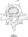
- FIGs. 1 and 2 illustrate a vertebral segment 100 with pedicles 102a and 102b that extend from the vertebral body 101.
- FIG. 2 illustrates the placement of pedicle screws 200 as known in the art.
- pedicle screws 200 have a threaded portion 208 that is screwed into the pedicle and head portions 204 and 206 respectively that connect to other fixation devices such as a rod 206.
- Pedicle screw fixation systems have been used in providing spinal stabilization and spinal fusion in patients with a variety of conditions such as degenerative spondylolisthesis, isthmic spondylolisthesis, fusion after decompression, spinal fractures, and surgically repaired spinal pseudoarthroses.
- the advent of rigid pedicle screw/rod fixation devices has led to a dramatic increase in the rate of arthrodesis (i.e. the surgical fusion of a joint) particularly for the treatment of degenerative disc disease and spondylolisthesis.
- arthrodesis i.e. the surgical fusion of a joint
- rigid instrumentation has enabled surgeons to maintain, improve, or fully reduce spondylolisthesis outright, and these devices have allowed for very aggressive strategies for decompression.
- typical pedicle screw fixation systems as known in the art are multi-component devices consisting of solid rods 206 that are longitudinally interconnected and anchored to adjacent vertebrae using pedicle screws such as pedicle screw 200.
- the screws and other components are generally made of stainless steel, titanium or other acceptable implantable material, typically metal alloys. The surgeon selects from among these components to construct a system suitable for a patient's anatomical and physiological requirements.
- Pedicle screws are similar to the screws used in long bones.
- pedicle screws are inserted into channels that are drilled or otherwise formed through the cancellous central axis of each vertebral pedicle 102a and 102b.
- the longitudinal connecting rods 206 usually span and brace two or more vertebrae and, as mentioned above, are connected to the screws 200. Each vertebra typically receives a pedicle screw in both pedicles.
- the connecting rods 206 are provided in pairs with each of the rods extending over one side of the spine.
- the screws hold their purchase within the bones through several mechanisms.
- One of the main sources of pullout resistance is obtained by the use of screw threads.
- the use of threads allows for better fixation due to increased contact area with the surrounding bone material. It is understood in the current art that placement of the screw in a manner such that it is directed towards the median plane of the vertebrae improves pullout resistance by allowing the screw to interact with a greater amount of bone material.
- Screw loosening as a result of constant back and forth toggling forces acting on the screw is also a cause for screw pullout. These forces can occur during regular flexion and extension motions of the spine ( Chao, C.K. et al. Increasing Bending Strength and Pullout Strength in Conical Pedicle Screws: Biomechanical Tests and Finite Element Analyses. J. Spinal Disorders & Techniques. 2008. 21 (2): 130-138, 2008 ).
- pedicle screws examples include US patent numbers 4,887,596 and 5,207,678 . Some more recent screws and screw systems have been proposed to address specific issues.
- a cannulated pedicle screw is provided in US publication number US2007/0299450 .
- the pedicle screw is provided with a central cannula or canal having an opening at the distal end of the screw. Once implanted, bone cement is injected into the cannula and into the joint between the screw and the bone.
- US patent number 7,037,309 provides another cannulated pedicle screw having a self-tapping distal tip.
- a screw of this type avoids the need for boring hole prior to insertion of the screw.
- US publication numbers US2005/0182409 and US2008/0015586 teach a device for dynamic stabilization of the spine and are directed to the problem of shear stresses on pedicle screws.
- the devices include pedicle screws that are provided with a head that connects to moveable elements.
- moveable elements In the course of regular motion, such elements are adapted to absorb compressive or expansive forces and to thereby reduce the amount of stresses translated to the screws.
- the moveable elements are often complicated devices as compared to the commonly known rods.
- US 2010/016903 discloses a posterior spinal fastener for insertion into a vertebra of a mammalian body, the vertebra having posterior elements and a vertebral body.
- the fastener includes an elongate member adapted for insertion into the vertebra.
- the elongate body has an anterior portion and a posterior portion.
- the anterior portion is arcuate in shape for placement in the vertebral body.
- the posterior portion has a length so as to be accessible at the posterior elements of the vertebra when the anterior portion is disposed in the vertebral body.
- a method of use of the posterior spinal fastener is also disclosed, in which the posterior spinal fastener is introduced into the vertebra at the posterior elements and arcuately extended into the vertebral body.
- the present invention relates to a bone screw according to claim 1.
- Preferred embodiments are set forth in the dependent claims.
- the present description provides a bone screw, in particular a pedicle screw which comprises an anchor portion and threaded sleeve portion adapted to engage the anchor portion.
- a channel can be created though the pedicle and into the vertebral body of the vertebra to facilitate the placement of the pedicle screws.
- the pedicle screw can then be inserted whereby the angled portion is impacted into place, followed by the threaded sleeve being threaded onto the treaded portion of the anchor portion and the screw head engaged onto the sleeve head to facilitate the attachment of fixation devices.
- the sleeve head and the screw head are engaged in a manner such that they form a ball and socket joint.
- the ball and socket joint allows the screw head to swivel while engaged to the sleeve head.
- the angled, nail portion is provided with a protrusion to act as a further anchor for the nail portion into the vertebra to resist pullout.
- the angled portion of the anchor portion may be provided with surface medication to allow for an increased amount of surface area of the nail portion in contact with surrounding bone material.
- the surface modifications can also further act as anchors for the nail portion into the vertebra. Such surface modifications can include studs and raised ridges.
- the angled portion has fenestrations that promote bony ingrowth into them. Such bony ingrowth further locks the nail portion into the vertebra.
- the following description is provided with reference to various embodiments thereof.
- the description will refer primarily to pedicle screws and to spinal stabilization.
- the screw described herein can be utilized in and/or for any bone anchoring or fixation application.
- the references herein to pedicle screws and to spinal fixation or fusion will be understood as being illustrative of a particular aspect of the description and are not intended to limit the description in any way.
- the bone screw described herein can, for example, be used in applications involving large bones such as the femur, tibia, fibula, ulna, etc. as well as for attaching cervical plates and cages to cervical vertebrae.
- distal and proximal are used. These terms are used for convenience only and are not intended to limit the description in any way.
- the term “distal” will be used in relation to that end of the screw of the description that is inserted into bone.
- proximal will be used to refer to the opposite end of the screw that extends outside of the bone into which the screw is implanted.
- anterior and anterior will be used herein in terms of the orientation of the spine in a mammal, such as a human. It will be understood that such terms are used purely to facilitate the description of the present bone screw and not to limit the screw in any way.
- FIG. 1 shows a plan view of a typical spinal vertebra 100.
- the vertebra 100 includes a vertebral body 101 which is mainly comprised of a core of cancellous bone 103.
- the outer portions of the vertebral body 101 are dense cortical bone 104, which is harder than cancellous bone 103.
- the posterior portion of the vertebra 100 is connected to the vertebral body 101 by pedicles 102a and 102b.
- the pedicles are formed of tough cortical bone on the outside and softer cancellous bone within.
- FIG. 2 is a sagittal cross sectional view of a spinal section showing adjacent lumbar vertebrae into which pedicle screws 200 of a known design are implanted.
- the screws have heads 202 and 204 respectively.
- each of the pedicle screws 200 is inserted through a respective pedicle 102a and 102b and into the cancellous bone 103 of the vertebral body 101.
- Two pedicle screws are inserted into separate vertebral bodies.
- the heads 202 and 204 of the screws 200 are connected to rods 206 in order to stabilize the two adjacent vertebrae.
- the stabilization is made possible as the screws and rods create a solid "brace" to hold the vertebrae in place. Their combination inhibits movement from occurring between the vertebrae and thus increases stability.
- each of the pedicle screws passes through a respective pedicle 102a and 102b.
- the bodies of the prior art pedicle screws 200a and 200b consist mainly of threaded portions 300a and 300b respectively.
- the screws also have proximal portions 301a and 302b which can be spherical, such as to connect with heads 202 and 204, which in turn facilitate connection to rods 206, as shown in FIG. 2 .
- the screws 200a and 200b are inserted through the pedicles 102a and 102b and into the vertebral body 101. This makes use of the anatomical structure of the vertebra and increases contact area between the bone and pedicle screws in order to resist screw pullout.
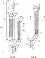
- the pedicle screw 400 comprises an anchor portion 401 and a threaded sleeve 404.
- the anchor portion 401 consists of a distal angled nail portion 403 and a proximal threaded portion 402.
- the proximal threaded portion 402 is comprised of a shaft having an external thread.
- the angled nail portion 403 comprises in the illustrated embodiment a square cross section but other cross sections are possible, as discussed below.
- the angled nail portion 403 may also include a tip, such as a pointed tip 413 at the distal end 415.
- the tip 413 is preferably provided to aid in the insertion of the nail portion 403 into a vertebra 100. It will be understood that in some embodiments, the pointed tip 413 may be omitted or replaced with another feature offering the same functionality. From the present description, it will also be understood that the nail portion serves as an anchor for the bone screw.
- the longitudinal axis of the angled nail portion 403 and the longitudinal axis of the threaded portion 402 are angled in relation to one another. As discussed further below, various degrees of angulation may be provided between the angled nail portion 403 and the threaded portion 402.
- the angled nail portion 403 may in one embodiment be provided with a protrusion 412 at the distal end 415.
- the protrusion 412 serves to increase the anchoring force when implanted in bone, such as vertebra 100 for the pedicle screw 400, particularly once bone regrowth has occurred post-implantation of the screw 400.
- the threaded portion 402 of the nail portion 401 may include a recess 414 to receive a setting tool for stabilizing the anchor portion 401.
- the setting tool may also be used to guide the threaded sleeve 404 during insertion.
- One example of the recess 414 is shown in FIG. 6B , wherein the recess 414 is shown as having a hexagonal shape.
- the shape of recess 414 is adapted to accommodate the shape of the setting tool.
- the recess 414 may be provided in any other shape. Another means of stabilizing the anchor portion is discussed below with respect to FIGs. 21A to 21H .
- the threaded sleeve 404 has a proximal end 417 and a distal end 418.
- the threaded sleeve has an external thread 406 on its outer surface and an internal bore 405 which may extend between the distal end 418 and the proximal end 417 of the threaded sleeve 404.
- the wall of the internal bore 405 is threaded by a thread referred to herein as an internal thread 407.
- the external thread 406 extends between the distal end 418 and the proximal end 417 of the threaded sleeve 404.
- the threaded sleeve 404 may also have a screw head 410 engaged to the sleeve head 408.
- the sleeve head 408 is shown as being generally spherical in shape, which is particularly advantageous since, as also shown in the figures, the sleeve head 408 and the screw head 410 form a ball and socket joint, as shown in FIG. 10 .
- the screw head 410 is allowed to move in various directions while being connected to the sleeve head 408.
- the sleeve head 408 may be provided with any variety of shapes.
- the screw head 410 may be integrally formed with the sleeve 404 so as to be a formed part of sleeve head 408.
- the screw head may be a separate component that is connected to the sleeve head 408 prior to or during insertion of the screw into bone or later.
- the screw head 410 may, for example, be threaded onto the sleeve head 408.
- the screw head 410a may include a post portion 420 that is inserted into the sleeve 404.
- Such a post 420 may be provided with an external thread that is adapted to cooperate with the internal thread of the sleeve 404.
- the head 410a may be secured to the post in any way.
- the sleeve head 408 may include an aperture 409 to permit the passage of a tool that can be used for placement of screw 400 into the vertebra 100.
- a passage 1000 comprises an open channel extending between the aperture 409 and the threaded internal bore 405, as shown in FIG. 10 .
- the passage 1000 allows for tools to pass through the aperture 409 and into the threaded internal bore 405.
- the radius of the passage 1000 may be varied depending on the tools used for placement of the anchor portion 401 and threaded sleeve 404 into the vertebra 100.
- the internal threads 407 are adapted to engage the threads of the threaded portion 402.
- the radius of the internal bore 405 is large enough to accommodate insertion of the threaded portion 402 of the anchor portion 401 into the bore 405 as the internal threads 407 are threaded onto the threaded portion 402.
- the bore 405 is adapted to receive the entire length of the threaded portion 402 of the anchor portion 401.
- the screw head 410 comprises a recess 411 or other such feature that enables the head 410 to engage a fixation device as known in the art.
- the fixation device may comprise rods 206 as described above.
- the description is not limited to the types of fixation devices that may be used. Similarly, the description is not limited to any particular form or function of the screw head 410.
- insertion, or implantation, of the screw 400 into a vertebra comprises a two-step procedure.
- the anchor portion 401 is inserted through a pedicle such as either pedicle 102a or 102b and into a vertebral body 101.
- the threaded sleeve 404 is implanted, by threading the sleeve 404 onto the threaded portion 402 of the anchor portion 401.
- the external threading provided thereon engages the bone of the pedicle.
- a channel for the anchor portion 401 is first created through the pedicle and the vertebral body to help facilitate the insertion of at least the anchor portion 401.
- a channel is created by removing bone material using a tool, such as a pedicle probe 1600 as shown in FIG. 16 .
- the channel is created by using the distal end 1601 of the pedicle probe 1600 to penetrate and remove or excavate bone material in the vertebra 100 along a path to enable the anchor portion 401 to be inserted.
- creating a channel as described above facilitates the insertion of the screw 400 by creating a passage for the insertion of the anchor portion 401 into the vertebra 100.
- the anchor portion 401 is inserted into the vertebra 100 by applying a force at its proximal end 416 to drive it into the vertebra 100.
- This force can, for example, be generated by hammering the proximal end 416 by using a suitable surgical tool as known in the art.
- the anchor portion 401 is inserted into the vertebra 100 through the passage created by the pedicle probe 1600.
- the anchor portion 401 is inserted through the pedicle 102a or 102b and into the vertebral body 101.
- the pointed tip 413 at the distal end 415 of the anchor portion 401 facilitates the insertion of the anchor portion 401 through the channel.
- the shape of the pointed tip 413 reduces resistance faced by the anchor portion 401.
- the bone material grows around, for example, the angled nail portion 403 of the anchor portion 401.
- the protrusion 412 is surrounded by bone material it along with the rest of the angled nail portion 403 acts to further anchor the screw 400 within the bone material.
- such an anchoring results in an increased resistance to pullout forces for the anchor portion 401.
- bone re-growth also occurs around the various threaded surfaces of the screw 300 that are exposed to the bone of the vertebra, thereby also increasing the pullout resistance of the screw.
- Various chemical or other treatments may also be used on portions of the screw and nail portions etc. to further enhance the anchoring of the screw within the bone.
- the anchor portion 401, and in particular the angled nail portion 403 may be referred to as an anchor for the subject bone screw.
- the threaded portion 402 is housed within the pedicle, such as either pedicle 102a or 102b. In the preferred example Z the entire threaded portion 402 is inserted into the pedicle however a portion may extend out of the pedicle.
- the threaded sleeve 404 can then be inserted, or implanted.
- the threaded sleeve 404 is inserted into the pedicle and threaded onto the threaded portion 402 of the anchor portion 401.
- a setting tool may be used to stabilize the anchor portion 401.
- the aperture 409 allows such a setting tool to pass into the proximal end 417 of the threaded sleeve 404, through the passage 1000 and into the internal bore 405.
- the setting tool can then engage the recess 414 of the anchor portion 401 and hold the anchor portion 401 steady as the threaded sleeve 404 is threaded onto the threaded portion 402 of the anchor portion 401.
- the setting tool can serve to guide the threaded sleeve 404 as it is threaded onto the threaded portion 402 of the anchor portion 401.
- slots 1100 may be provided on the sleeve 404, at a location near the junction of the external threads 406 and the sleeve head 408.
- the slots 1100 can be adapted to engage with another setting tool to aid in threading the sleeve 404 onto the threaded portion 402.
- the threaded sleeve 404 can be threaded onto the anchor portion 401 by using a tool engaged with the slots 1100 or, alternatively, the sleeve 404 can be manually implanted by the surgeon.
- the external threads 406 engage of the sleeve 404 engage the bone material of the pedicle, such as pedicle 102b as seen in FIG. 16 .
- the bone material provides the screw 400 with purchase within the pedicle and increases the amount of surface area in contact between the screw 400 and the vertebra 100. This engagement between the threads and the bone material further increases resistance to pullout forces.
- the screw head 410 can be engaged with the sleeve head 408. Once placed, the screw head 410 can be swiveled about the sleeve head 408 in view of the ball and socket arrangement as discussed previously. In this way, the screw head 410 can be positioned as needed so as to allow connection to, for example, spinal fixation devices such as rods 206. As known to persons skilled in the art, the rods 206 extend along a portion of the spine spanning two or more vertebrae and are connected thereto so as to stabilize such spinal region.
- the pedicle screw 400 described herein incorporates a threaded portion that engages bone material, as with known pedicle screws, but also incorporates a further enhancement achieved by the angled nail portion 403, which results in increased pullout resistance. As discussed above, the pullout resistance offered by the screw 400 described herein can be further enhanced by providing the protrusion 412.
- the present description is not limited to any particular angular configuration of the anchor portion 401.
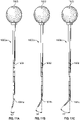
- various alternative arrangements are shown in FIGs. 5A-C , wherein angles of 15°, 30° and 45° are illustrated between the angled nail portion 403 and the threaded portion 402.
- the present description is not limited to any specific angle of the anchor portion 401.
- the screw 400 of the present description can be varied to further enhance pullout resistance.
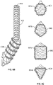
- the angled nail portion 403b of the anchor portion 401 can be provided with one or more rows of raised ridges or spikes etc. 600 positioned along the body of the angled nail portion 403b.
- the ridges or spikes would serve to further enhance the anchoring of the anchor portion 401 within the bone, particularly once bone re-growth has occurred.
- the raised ridges or spikes are generally pyramidal in shape. However, various other shapes of these features may be used.
- FIG. 6C shows exemplary cross sections of the angled nail portion 403b across line B-B of FIG. 6A .
- a hexagonal cross section 601a, pentagonal cross section 601b, square or rectangular cross section 601c or a triangular cross section 601d are different embodiments of the anchor portion 401. The description is not limited to any particular cross sectional shape of the angled nail portion 403.
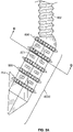
- FIGs. 7A and 7B illustrate an alternative to the spikes illustrated in FIGs. 6A , 6B .
- the anchor portion 401 has an angled nail portion 403c that is provided with one or more rows of scales 700.
- the scales project radially outwardly and in a proximal direction, that is away from the distal end of the nail portion.
- FIG. 7C shows cross sections across line C-C of the angled nail portion 403c.
- a hexagonal cross section 701a, a pentagon cross section 701b, a square or rectangular cross section 701c or a triangular cross section 701d are all possible as different embodiments of the cross section of angled nail portion 403c.
- FIGs. 8A and 8B show yet another embodiment for enhancing the pullout resistance of the screw of the present description.
- the angled nail portion 403d of the nail portion is provided with one or more rows of ridges or spikes 800, such as those discussed above.
- the angled nail portion 403d of FIGs. 8A and 8B is further provided with one or more fenestrations 801.
- the fenestrations comprise openings into the lumen of the angled nail portion 403d, into which bone is allowed to grow. As will be understood, bone ingrowth into the fenestrations further enhances the grip of the anchor portion 401 in the vertebra 100.
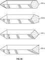
- FIG. 8C shows various embodiments of the cross section of the angled nail portion 403d across the line D-D, with hexagonal 802a, pentagonal 802b, square 802c and triangular 802d cross sections possible.
- the shape of the angled nail portion 403d is not limited to these shapes.
- the course of the fenestrations 801 can also differ with the purpose of promoting bony ingrowth.
- 801a shows the fenestrations in the hexagonal section, 801b in the pentagonal section, 801c in the square section, 801d in the triangular section.
- the connections between the fenestrations 801 are also variable in depth, number and direction, and can be varied to further facilitate bony ingrowth and allow for greater pullout resistance.
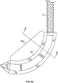
- FIGs. 9A and 9B A bone screw not according to the invention is illustrated in FIGs. 9A and 9B , wherein the anchor portion 401 is provided with a nail portion 403e that is curved to form a "hook" like arrangement. It will be understood that the surface of the angled or nail portion 403e of FIGs. 9A and 9B can be modified as described above to include spikes, scales and/or fenestrations as may be desired or required.
- the nail portion 403e can have varying cross sections across line E-E of the nail portion 403d.
- a hexagonal cross section 901a, pentagonal cross section 901b, square or rectangular cross section 901c or triangular cross section 901d are all possible as different examples for the cross sectional shape of the nail portion 403e.
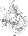
- FIGS. 14 and 15 show the pedicle screw 400 according to an embodiment, as implanted in a vertebra 100. These figures illustrate the difference in how the screw of the description captures bone material over that of known pedicle screws, such as pedicle screw 200.
- the external threads 406 of the threaded sleeve 404 also allow purchase with the bone material of the pedicle 1b.
- the presence of the protrusion 412 acts as an anchor into the bone material of vertebra 100 and also increases resistance to pullout. That is, a pedicle screw 200 as known in the art is shown passing straight through the pedicle 102a and into the vertebral body 101, whereas the screw 400 according to an embodiment of the description is shown with its angled nail portion 403 and threaded portion 402 in engagement with the vertebral body 101 and the pedicle 102b. As can be seen, the screw 400 contacts and grips more bone material than the known screw 200.
- a tool such as pedicle probe 1600 shown in FIGS. 16A and 16B , may be used to create a channel into which at least the anchor portion 401 of the screw 400 is inserted or implanted.
- the probe 1600 is inserted and pushed into the vertebra so as to carve out bone material from the pedicles and the vertebral body 101.
- the probe 1600 comprises an angled distal portion 1601, a middle portion 1602, and a proximal portion 1603.
- the distal portion 1601 is preferably angled with respect to the rest of the tool. As will be understood, such an angle allows the aforementioned channel to be formed in a manner that accommodates the angled portion of the anchor portion 401.
- pedicle probe 1600 can be provided with any degree of angulation between the distal portion 1601 and the middle portion 1602. As will be understood, the desired pedicle probe may be chosen based on the angle provided on the angled portion 401 of the screw 400.
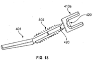
- the bone screw 400b has a sleeve 404b and an anchor (or nail) portion 401b.
- the anchor portion 401b is adapted to be inserted into a cavity formed in bone.
- the anchor portion 401b includes an angled nail portion 403b.
- the angled nail portion 403b includes a first surface 430 that is generally smooth and an opposite second surface 432 that includes groove or serrations.
- the grooves or serrations serve to assist in anchoring the anchor portion 401b into bone.
- the angled nail portion 403b is optionally provided with a smooth finish on a portion of its outer surface. Such an arrangement would be helpful in the event that the screw, in particular the anchor portion 401b needs to be extracted. In such case, only the serrated portion needs to be extricated from surrounding bone, thereby facilitating removal of the anchor portion 401b.
- the serrations may optionally be provided over the entire surface of the angled nail portion 403b or such portion may have no serrations. In the latter case, the angled nail portion 403b may be provided with other bone adhering finishes or treatments as needed.
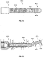
- the sleeve 404b illustrated in FIGs. 19 and 20 is similar to that described above. Specifically, as shown in FIG. 20 , the sleeve 404b includes an inner bore that is adapted to receive at least the proximal end of the anchor portion 401b. As above, a portion of the anchor portion 401b adjacent the proximal end thereof is received within the inner bore of the sleeve 404b. As discussed above, the inner bore of the sleeve 404b and the outer surface of the portion of the anchor portion 401b received within the inner bore are provided with cooperating thread, whereby the sleeve 404b can be screwed onto the anchor portion. The outer surface of the distal portion of the sleeve 404b is provided with threading 406b, which is suitable for being screwed into the bone in question.
- FIGs. 21A to 21 H Another embodiment of the bone screw is illustrated in FIGs. 21A to 21 H , which also illustrate an example of a bone screw system.
- elements similar to those discussed above are identified with like reference numerals but with the letter "c" added for clarity.
- the anchor portion 401c shown in FIGs. 21A to 21H is similar to the anchor portion 401b discussed above.
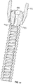
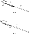
- FIG. 21A illustrates an inserter 500 that is used to assist in the implantation of the bone screw.
- the inserter 500 comprises an elongate, probe-like structure having a proximal end 502 and a distal end 504.
- an outer sleeve 404c is combined with the inserter 500.
- the inserter 500 is inserted through the head 410c and through the bore of the sleeve 404c.
- the distal end 504 of the inserter is inserted through the head 410c and through the proximal end of the sleeve 404c and allowed to protrude through the distal end of the sleeve 404c.
- the distal end 504 of the inserter 500 is provided with a probe tip 508 and a first connector portion 510 that forms the distal end of the threading 506.
- the proximal end 416c of the anchor portion 401c includes a second connector portion 512.
- the first and second connector portions 510, 512 are adapted to be engaged.
- the first connector portion 510 comprises a pair of tabs and the second connector portion 512 comprises a pair of corresponding slots, which are adapted to receive the tabs of the first connector portion 510. It will be understood that other forms of connection may be used, for the purpose described below.
- FIG. 21D illustrates the anchor portion 401c and inserter 500 when combined, that is, when the first and second connector portions are engaged.
- the sleeve 404c is slid down the inserter and the thread provided on the inner bore of the sleeve 404c (as described above) is allowed to engage the thread provided on threaded portion 402c of the anchor portion 401c.
- Such engagement of the sleeve 404c and the anchor portion 401c is similar to the arrangement discussed above.
- the sleeve 404c is then screwed onto the anchor portion 401c in the same manner as discussed above. Any means may be used to turn the sleeve 404c for securing it to the anchor portion 401c as would be apparent from the present description.
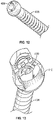
- FIG. 21F illustrates the system once the sleeve 404c is fully screwed on to the anchor portion 401c.
- the inserter 500 can be used to hold and stabilize the anchor portion 401c.
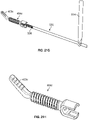
- FIG.21G illustrates an optional handle 514 that may be used to hold the inserter 500 during the above procedure.
- FIG. 21 H illustrates the assembled bone screw 400c according to this embodiment as it would appear once implanted and once the inserter is removed. As illustrated and as would be understood, the angled nail portion 403c of the anchor portion 401c and the threaded portion 406c of the sleeve 404c are exposed to the bone material (which is not shown).
- the bone screw described herein provides an improvement over known screws by enhancing the anchoring of the screw to the bone material in which it is implanted.
- the screws and screw components of the present description can be made of any material as will be known to persons skilled in the art.
- the elements of the screw may be made of: metals or metal alloys such as stainless steel, titanium, titanium alloys, nickeltitanium alloys (such as Nitinol TM ), cobalt-chrome alloys; plastic and/or thermoplastic polymers (such as PEEK TM ); carbon fiber; or any other material, or combination of materials, commonly associated with bone screws.
- the surface of the screws and screw components described herein may optionally be coated with any known substances for improving their placement or adhesion within the bone or for promoting bone ingrowth.
- the outer surface of the screw may be coated with hydroxyapatite to promote osseointegration of the screw and, thereby, allowing increased resistance to screw pullout.
Claims (10)
- Vis à os (400) comprenant :a) un composant d'ancrage (401) ayant des première et deuxième extrémités et comprenant une partie de clou (403) adjacente à la deuxième extrémité et une partie filetée (402) comprenant un filetage externe adjacente à la première extrémité, la partie de clou et la partie filetée étant adaptées pour être insérées dans l'os ; et,b) un composant de manchon généralement cylindrique (404) ayant des première et deuxième extrémités et un alésage (405) s'étendant à travers celles-ci, l'alésage étant fileté (407) sur au moins une partie de celui-ci adjacente à la deuxième extrémité, le composant de manchon comprenant une surface extérieure filetée (406) adjacente à au moins la deuxième extrémité, la surface extérieure filetée étant adaptée pour être fixée dans l'os ;- dans laquelle la deuxième extrémité du composant de manchon est adaptée pour recevoir la première extrémité du composant d'ancrage, et dans laquelle la partie filetée (402) du composant d'ancrage (401) est adaptée pour s'engager dans l'alésage fileté (405) du composant de manchon (404) ;- caractérisé en ce que :- la partie de clou (403) et la partie filetée (402) du composant d'ancrage ont des axes longitudinaux respectifs, dans laquelle l'axe longitudinal de la partie de clou est incliné par rapport à l'axe longitudinal de la partie filetée.
- Vis à os selon la revendication 1, dans laquelle la partie de clou est adaptée pour permettre la croissance osseuse.
- Vis à os selon la revendication 2, dans laquelle la partie de clou (403) est pourvue d'une ou plusieurs dentelures, rainures, ouvertures et parties surélevées pour permettre la croissance osseuse.
- Vis à os selon l'une quelconque des revendications 1 à 3, dans laquelle la première extrémité du composant de manchon (404) comprend une tête (410) adaptée pour être connectée à un dispositif de fixation osseuse.
- Vis à os selon la revendication 4, dans laquelle la tête est formée d'un seul tenant avec le composant de manchon ou est reliée à celui-ci.
- Vis à os selon la revendication 4, dans laquelle la tête est adaptée pour pivoter autour de l'axe longitudinal du composant de manchon.
- Vis à os selon la revendication 4, dans laquelle la deuxième extrémité du composant d'ancrage comprend un moyen de connexion à un dispositif de positionnement pour stabiliser le composant d'ancrage lors de la connexion au composant de manchon.
- Vis à os selon l'une quelconque des revendications 1 à 7, dans laquelle l'angle entre l'axe longitudinal de la partie de clou et la partie filetée est compris entre 15 et 45 degrés.
- Vis à os selon l'une quelconque des revendications 1 à 8, dans laquelle la partie de clou comprend une saillie (412) pour l'ancrage à l'os.
- Vis à os selon l'une quelconque des revendications 1 à 9, dans laquelle la vis à os est une vis pédiculaire.
Applications Claiming Priority (2)
| Application Number | Priority Date | Filing Date | Title |
|---|---|---|---|
| US201462092740P | 2014-12-16 | 2014-12-16 | |
| PCT/US2015/066194 WO2016100570A1 (fr) | 2014-12-16 | 2015-12-16 | Vis à os |
Publications (3)
| Publication Number | Publication Date |
|---|---|
| EP3232959A1 EP3232959A1 (fr) | 2017-10-25 |
| EP3232959A4 EP3232959A4 (fr) | 2018-08-22 |
| EP3232959B1 true EP3232959B1 (fr) | 2022-04-27 |
Family
ID=56127562
Family Applications (1)
| Application Number | Title | Priority Date | Filing Date |
|---|---|---|---|
| EP15871023.6A Active EP3232959B1 (fr) | 2014-12-16 | 2015-12-16 | Vis à os |
Country Status (10)
| Country | Link |
|---|---|
| US (1) | US10327819B2 (fr) |
| EP (1) | EP3232959B1 (fr) |
| JP (1) | JP6864620B2 (fr) |
| KR (1) | KR102594552B1 (fr) |
| CN (1) | CN107106212B (fr) |
| AU (1) | AU2015364631C1 (fr) |
| CA (1) | CA2971412A1 (fr) |
| DK (1) | DK3232959T3 (fr) |
| ES (1) | ES2918002T3 (fr) |
| WO (1) | WO2016100570A1 (fr) |
Families Citing this family (4)
| Publication number | Priority date | Publication date | Assignee | Title |
|---|---|---|---|---|
| EP3524181B1 (fr) * | 2018-02-09 | 2021-11-10 | Biedermann Technologies GmbH & Co. KG | Système d'ancrage osseux et instrument allongé |
| CN109223155A (zh) * | 2018-10-29 | 2019-01-18 | 广州市健齿生物科技有限公司 | 一种锁定钛板内固定装置 |
| US20230023449A1 (en) * | 2021-07-20 | 2023-01-26 | Globus Medical, Inc. | Interlaminar lumbar interbody fusion system and associated robotic systems |
| US11534309B1 (en) | 2021-07-20 | 2022-12-27 | Globus Medical Inc. | Interlaminar lumbar interbody fusion implants, intradiscal implants, instruments, and methods |
Family Cites Families (15)
| Publication number | Priority date | Publication date | Assignee | Title |
|---|---|---|---|---|
| US4790303A (en) * | 1987-03-11 | 1988-12-13 | Acromed Corporation | Apparatus and method for securing bone graft |
| US4887596A (en) | 1988-03-02 | 1989-12-19 | Synthes (U.S.A.) | Open backed pedicle screw |
| DE3923996A1 (de) | 1989-07-20 | 1991-01-31 | Lutz Biedermann | Aufnahmeteil zum gelenkigen verbinden mit einer schraube zum bilden einer pedikelschraube |
| CN2309804Y (zh) * | 1997-11-21 | 1999-03-10 | 兰州记忆合金有限公司 | 具有自紧固功能的骑缝钉 |
| CA2390912C (fr) | 2001-07-05 | 2008-01-29 | Depuy France | Vis autotaraudeuse pour chirurgie de petits os |
| US20050143735A1 (en) * | 2003-04-29 | 2005-06-30 | Kyle Richard F. | Double compression unloadable screw system |
| US7635379B2 (en) | 2003-05-02 | 2009-12-22 | Applied Spine Technologies, Inc. | Pedicle screw assembly with bearing surfaces |
| CN2652344Y (zh) * | 2003-10-15 | 2004-11-03 | 孙明林 | 椎体滑脱复位用提拉螺钉 |
| EP1835859A2 (fr) | 2004-12-31 | 2007-09-26 | Ji-Hoon Her | Vis a pedoncule et dispositif d'injection de ciment osseux dans l'os |
| US8277485B2 (en) | 2006-06-07 | 2012-10-02 | Spinadyne, Inc. | Pedicle screw system |
| US8951295B2 (en) * | 2008-04-21 | 2015-02-10 | Total Connect Spine, Llc | Posterior spinal fastener |
| US10631994B2 (en) | 2012-10-12 | 2020-04-28 | Smith & Nephew, Inc. | Fusion Implant |
| ES2578295T3 (es) | 2012-11-14 | 2016-07-22 | Biedermann Technologies Gmbh & Co. Kg | Clavo para hueso para el talón |
| CN203176123U (zh) * | 2013-04-27 | 2013-09-04 | 浙江捷能汽车零部件有限公司 | 一种轻桥前轴用主销限位螺钉 |
| US9579123B2 (en) | 2014-09-19 | 2017-02-28 | Globus Medical, Inc. | Orthopedic stabilization devices and methods for installation thereof |
-
2015
- 2015-12-16 ES ES15871023T patent/ES2918002T3/es active Active
- 2015-12-16 CN CN201580068920.XA patent/CN107106212B/zh active Active
- 2015-12-16 EP EP15871023.6A patent/EP3232959B1/fr active Active
- 2015-12-16 WO PCT/US2015/066194 patent/WO2016100570A1/fr active Application Filing
- 2015-12-16 US US15/535,783 patent/US10327819B2/en active Active
- 2015-12-16 CA CA2971412A patent/CA2971412A1/fr not_active Abandoned
- 2015-12-16 DK DK15871023.6T patent/DK3232959T3/da active
- 2015-12-16 JP JP2017533386A patent/JP6864620B2/ja active Active
- 2015-12-16 KR KR1020177018956A patent/KR102594552B1/ko active IP Right Grant
- 2015-12-16 AU AU2015364631A patent/AU2015364631C1/en active Active
Also Published As
| Publication number | Publication date |
|---|---|
| CN107106212B (zh) | 2020-11-20 |
| KR20170095931A (ko) | 2017-08-23 |
| CA2971412A1 (fr) | 2016-06-23 |
| ES2918002T3 (es) | 2022-07-13 |
| AU2015364631A1 (en) | 2017-07-06 |
| WO2016100570A1 (fr) | 2016-06-23 |
| KR102594552B1 (ko) | 2023-10-26 |
| EP3232959A1 (fr) | 2017-10-25 |
| US10327819B2 (en) | 2019-06-25 |
| EP3232959A4 (fr) | 2018-08-22 |
| DK3232959T3 (da) | 2022-05-30 |
| AU2015364631B2 (en) | 2019-09-12 |
| US20170360480A1 (en) | 2017-12-21 |
| CN107106212A (zh) | 2017-08-29 |
| JP2017538546A (ja) | 2017-12-28 |
| AU2015364631C1 (en) | 2019-12-12 |
| JP6864620B2 (ja) | 2021-04-28 |
Similar Documents
| Publication | Publication Date | Title |
|---|---|---|
| US20210212734A1 (en) | Implants for spinal fixation or fusion | |
| US11678997B2 (en) | Implants for spinal fixation and or fusion | |
| US11369419B2 (en) | Implants for spinal fixation and or fusion | |
| US9592081B2 (en) | System and method for stabilizing a posterior fusion over motion segments | |
| US5643264A (en) | Iliac screw | |
| US7060066B2 (en) | Spinal fixation support device and methods of using | |
| US20120184993A1 (en) | Expandable facet screw | |
| US9636158B2 (en) | Pedicle screw with reverse spiral cut and methods thereof | |
| US20120010668A1 (en) | Expandable surgical implant | |
| US10368923B2 (en) | Bone fixation system | |
| US20130041412A1 (en) | Flexible pedicle screws | |
| EP3232959B1 (fr) | Vis à os | |
| US20220087724A1 (en) | Bone-anchoring device for a pedicle access | |
| US20220183734A1 (en) | Surgical implant and method of use | |
| US20170209183A1 (en) | Surgical implant and method of use |
Legal Events
| Date | Code | Title | Description |
|---|---|---|---|
| STAA | Information on the status of an ep patent application or granted ep patent |
Free format text: STATUS: THE INTERNATIONAL PUBLICATION HAS BEEN MADE |
|
| PUAI | Public reference made under article 153(3) epc to a published international application that has entered the european phase |
Free format text: ORIGINAL CODE: 0009012 |
|
| STAA | Information on the status of an ep patent application or granted ep patent |
Free format text: STATUS: REQUEST FOR EXAMINATION WAS MADE |
|
| 17P | Request for examination filed |
Effective date: 20170615 |
|
| AK | Designated contracting states |
Kind code of ref document: A1 Designated state(s): AL AT BE BG CH CY CZ DE DK EE ES FI FR GB GR HR HU IE IS IT LI LT LU LV MC MK MT NL NO PL PT RO RS SE SI SK SM TR |
|
| AX | Request for extension of the european patent |
Extension state: BA ME |
|
| DAV | Request for validation of the european patent (deleted) | ||
| DAX | Request for extension of the european patent (deleted) | ||
| A4 | Supplementary search report drawn up and despatched |
Effective date: 20180723 |
|
| RIC1 | Information provided on ipc code assigned before grant |
Ipc: A61B 17/16 20060101ALI20180717BHEP Ipc: A61B 17/00 20060101ALI20180717BHEP Ipc: A61B 17/86 20060101ALI20180717BHEP Ipc: A61B 17/88 20060101ALI20180717BHEP Ipc: A61B 17/70 20060101AFI20180717BHEP |
|
| REG | Reference to a national code |
Ref country code: DE Ref legal event code: R079 Ref document number: 602015078581 Country of ref document: DE Free format text: PREVIOUS MAIN CLASS: A61B0017580000 Ipc: A61B0017700000 |
|
| RIC1 | Information provided on ipc code assigned before grant |
Ipc: A61B 17/88 20060101ALI20211021BHEP Ipc: A61B 17/00 20060101ALI20211021BHEP Ipc: A61B 17/86 20060101ALI20211021BHEP Ipc: A61B 17/16 20060101ALI20211021BHEP Ipc: A61B 17/70 20060101AFI20211021BHEP |
|
| GRAP | Despatch of communication of intention to grant a patent |
Free format text: ORIGINAL CODE: EPIDOSNIGR1 |
|
| STAA | Information on the status of an ep patent application or granted ep patent |
Free format text: STATUS: GRANT OF PATENT IS INTENDED |
|
| INTG | Intention to grant announced |
Effective date: 20211203 |
|
| GRAS | Grant fee paid |
Free format text: ORIGINAL CODE: EPIDOSNIGR3 |
|
| GRAA | (expected) grant |
Free format text: ORIGINAL CODE: 0009210 |
|
| STAA | Information on the status of an ep patent application or granted ep patent |
Free format text: STATUS: THE PATENT HAS BEEN GRANTED |
|
| RAP3 | Party data changed (applicant data changed or rights of an application transferred) |
Owner name: NEVADA NEUROSURGERY |
|
| RAP1 | Party data changed (applicant data changed or rights of an application transferred) |
Owner name: SPINEPOINT, LLC |
|
| AK | Designated contracting states |
Kind code of ref document: B1 Designated state(s): AL AT BE BG CH CY CZ DE DK EE ES FI FR GB GR HR HU IE IS IT LI LT LU LV MC MK MT NL NO PL PT RO RS SE SI SK SM TR |
|
| REG | Reference to a national code |
Ref country code: GB Ref legal event code: FG4D |
|
| REG | Reference to a national code |
Ref country code: CH Ref legal event code: EP |
|
| REG | Reference to a national code |
Ref country code: AT Ref legal event code: REF Ref document number: 1486332 Country of ref document: AT Kind code of ref document: T Effective date: 20220515 |
|
| REG | Reference to a national code |
Ref country code: DE Ref legal event code: R096 Ref document number: 602015078581 Country of ref document: DE |
|
| REG | Reference to a national code |
Ref country code: IE Ref legal event code: FG4D |
|
| REG | Reference to a national code |
Ref country code: DK Ref legal event code: T3 Effective date: 20220523 |
|
| REG | Reference to a national code |
Ref country code: NL Ref legal event code: FP |
|
| REG | Reference to a national code |
Ref country code: SE Ref legal event code: TRGR |
|
| REG | Reference to a national code |
Ref country code: ES Ref legal event code: FG2A Ref document number: 2918002 Country of ref document: ES Kind code of ref document: T3 Effective date: 20220713 |
|
| REG | Reference to a national code |
Ref country code: LT Ref legal event code: MG9D |
|
| REG | Reference to a national code |
Ref country code: AT Ref legal event code: MK05 Ref document number: 1486332 Country of ref document: AT Kind code of ref document: T Effective date: 20220427 |
|
| PG25 | Lapsed in a contracting state [announced via postgrant information from national office to epo] |
Ref country code: PT Free format text: LAPSE BECAUSE OF FAILURE TO SUBMIT A TRANSLATION OF THE DESCRIPTION OR TO PAY THE FEE WITHIN THE PRESCRIBED TIME-LIMIT Effective date: 20220829 Ref country code: NO Free format text: LAPSE BECAUSE OF FAILURE TO SUBMIT A TRANSLATION OF THE DESCRIPTION OR TO PAY THE FEE WITHIN THE PRESCRIBED TIME-LIMIT Effective date: 20220727 Ref country code: LT Free format text: LAPSE BECAUSE OF FAILURE TO SUBMIT A TRANSLATION OF THE DESCRIPTION OR TO PAY THE FEE WITHIN THE PRESCRIBED TIME-LIMIT Effective date: 20220427 Ref country code: HR Free format text: LAPSE BECAUSE OF FAILURE TO SUBMIT A TRANSLATION OF THE DESCRIPTION OR TO PAY THE FEE WITHIN THE PRESCRIBED TIME-LIMIT Effective date: 20220427 Ref country code: GR Free format text: LAPSE BECAUSE OF FAILURE TO SUBMIT A TRANSLATION OF THE DESCRIPTION OR TO PAY THE FEE WITHIN THE PRESCRIBED TIME-LIMIT Effective date: 20220728 Ref country code: FI Free format text: LAPSE BECAUSE OF FAILURE TO SUBMIT A TRANSLATION OF THE DESCRIPTION OR TO PAY THE FEE WITHIN THE PRESCRIBED TIME-LIMIT Effective date: 20220427 Ref country code: BG Free format text: LAPSE BECAUSE OF FAILURE TO SUBMIT A TRANSLATION OF THE DESCRIPTION OR TO PAY THE FEE WITHIN THE PRESCRIBED TIME-LIMIT Effective date: 20220727 Ref country code: AT Free format text: LAPSE BECAUSE OF FAILURE TO SUBMIT A TRANSLATION OF THE DESCRIPTION OR TO PAY THE FEE WITHIN THE PRESCRIBED TIME-LIMIT Effective date: 20220427 |
|
| PG25 | Lapsed in a contracting state [announced via postgrant information from national office to epo] |
Ref country code: RS Free format text: LAPSE BECAUSE OF FAILURE TO SUBMIT A TRANSLATION OF THE DESCRIPTION OR TO PAY THE FEE WITHIN THE PRESCRIBED TIME-LIMIT Effective date: 20220427 Ref country code: PL Free format text: LAPSE BECAUSE OF FAILURE TO SUBMIT A TRANSLATION OF THE DESCRIPTION OR TO PAY THE FEE WITHIN THE PRESCRIBED TIME-LIMIT Effective date: 20220427 Ref country code: LV Free format text: LAPSE BECAUSE OF FAILURE TO SUBMIT A TRANSLATION OF THE DESCRIPTION OR TO PAY THE FEE WITHIN THE PRESCRIBED TIME-LIMIT Effective date: 20220427 Ref country code: IS Free format text: LAPSE BECAUSE OF FAILURE TO SUBMIT A TRANSLATION OF THE DESCRIPTION OR TO PAY THE FEE WITHIN THE PRESCRIBED TIME-LIMIT Effective date: 20220827 |
|
| REG | Reference to a national code |
Ref country code: DE Ref legal event code: R097 Ref document number: 602015078581 Country of ref document: DE |
|
| PG25 | Lapsed in a contracting state [announced via postgrant information from national office to epo] |
Ref country code: SM Free format text: LAPSE BECAUSE OF FAILURE TO SUBMIT A TRANSLATION OF THE DESCRIPTION OR TO PAY THE FEE WITHIN THE PRESCRIBED TIME-LIMIT Effective date: 20220427 Ref country code: SK Free format text: LAPSE BECAUSE OF FAILURE TO SUBMIT A TRANSLATION OF THE DESCRIPTION OR TO PAY THE FEE WITHIN THE PRESCRIBED TIME-LIMIT Effective date: 20220427 Ref country code: RO Free format text: LAPSE BECAUSE OF FAILURE TO SUBMIT A TRANSLATION OF THE DESCRIPTION OR TO PAY THE FEE WITHIN THE PRESCRIBED TIME-LIMIT Effective date: 20220427 Ref country code: EE Free format text: LAPSE BECAUSE OF FAILURE TO SUBMIT A TRANSLATION OF THE DESCRIPTION OR TO PAY THE FEE WITHIN THE PRESCRIBED TIME-LIMIT Effective date: 20220427 Ref country code: CZ Free format text: LAPSE BECAUSE OF FAILURE TO SUBMIT A TRANSLATION OF THE DESCRIPTION OR TO PAY THE FEE WITHIN THE PRESCRIBED TIME-LIMIT Effective date: 20220427 |
|
| PGFP | Annual fee paid to national office [announced via postgrant information from national office to epo] |
Ref country code: IT Payment date: 20221122 Year of fee payment: 8 |
|
| PLBE | No opposition filed within time limit |
Free format text: ORIGINAL CODE: 0009261 |
|
| STAA | Information on the status of an ep patent application or granted ep patent |
Free format text: STATUS: NO OPPOSITION FILED WITHIN TIME LIMIT |
|
| PG25 | Lapsed in a contracting state [announced via postgrant information from national office to epo] |
Ref country code: AL Free format text: LAPSE BECAUSE OF FAILURE TO SUBMIT A TRANSLATION OF THE DESCRIPTION OR TO PAY THE FEE WITHIN THE PRESCRIBED TIME-LIMIT Effective date: 20220427 |
|
| 26N | No opposition filed |
Effective date: 20230130 |
|
| PGFP | Annual fee paid to national office [announced via postgrant information from national office to epo] |
Ref country code: ES Payment date: 20230102 Year of fee payment: 8 Ref country code: CH Payment date: 20230101 Year of fee payment: 8 |
|
| PG25 | Lapsed in a contracting state [announced via postgrant information from national office to epo] |
Ref country code: SI Free format text: LAPSE BECAUSE OF FAILURE TO SUBMIT A TRANSLATION OF THE DESCRIPTION OR TO PAY THE FEE WITHIN THE PRESCRIBED TIME-LIMIT Effective date: 20220427 |
|
| P01 | Opt-out of the competence of the unified patent court (upc) registered |
Effective date: 20230414 |
|
| REG | Reference to a national code |
Ref country code: BE Ref legal event code: MM Effective date: 20221231 |
|
| PG25 | Lapsed in a contracting state [announced via postgrant information from national office to epo] |
Ref country code: LU Free format text: LAPSE BECAUSE OF NON-PAYMENT OF DUE FEES Effective date: 20221216 |
|
| PG25 | Lapsed in a contracting state [announced via postgrant information from national office to epo] |
Ref country code: IE Free format text: LAPSE BECAUSE OF NON-PAYMENT OF DUE FEES Effective date: 20221216 |
|
| PG25 | Lapsed in a contracting state [announced via postgrant information from national office to epo] |
Ref country code: BE Free format text: LAPSE BECAUSE OF NON-PAYMENT OF DUE FEES Effective date: 20221231 |
|
| PGFP | Annual fee paid to national office [announced via postgrant information from national office to epo] |
Ref country code: NL Payment date: 20231121 Year of fee payment: 9 |
|
| PGFP | Annual fee paid to national office [announced via postgrant information from national office to epo] |
Ref country code: GB Payment date: 20231121 Year of fee payment: 9 |
|
| PGFP | Annual fee paid to national office [announced via postgrant information from national office to epo] |
Ref country code: SE Payment date: 20231121 Year of fee payment: 9 Ref country code: FR Payment date: 20231122 Year of fee payment: 9 Ref country code: DK Payment date: 20231121 Year of fee payment: 9 Ref country code: DE Payment date: 20231121 Year of fee payment: 9 |
|
| PG25 | Lapsed in a contracting state [announced via postgrant information from national office to epo] |
Ref country code: HU Free format text: LAPSE BECAUSE OF FAILURE TO SUBMIT A TRANSLATION OF THE DESCRIPTION OR TO PAY THE FEE WITHIN THE PRESCRIBED TIME-LIMIT; INVALID AB INITIO Effective date: 20151216 |