EP3232745B1 - Low power, temperature regulated circuit for precision integrated circuits - Google Patents
Low power, temperature regulated circuit for precision integrated circuits Download PDFInfo
- Publication number
- EP3232745B1 EP3232745B1 EP17166640.7A EP17166640A EP3232745B1 EP 3232745 B1 EP3232745 B1 EP 3232745B1 EP 17166640 A EP17166640 A EP 17166640A EP 3232745 B1 EP3232745 B1 EP 3232745B1
- Authority
- EP
- European Patent Office
- Prior art keywords
- frame
- wafer
- suspended mass
- integrated circuit
- heater
- Prior art date
- Legal status (The legal status is an assumption and is not a legal conclusion. Google has not performed a legal analysis and makes no representation as to the accuracy of the status listed.)
- Active
Links
Images

Classifications
-
- H—ELECTRICITY
- H10—SEMICONDUCTOR DEVICES; ELECTRIC SOLID-STATE DEVICES NOT OTHERWISE PROVIDED FOR
- H10W—GENERIC PACKAGES, INTERCONNECTIONS, CONNECTORS OR OTHER CONSTRUCTIONAL DETAILS OF DEVICES COVERED BY CLASS H10
- H10W72/00—Interconnections or connectors in packages
- H10W72/071—Connecting or disconnecting
-
- H—ELECTRICITY
- H10—SEMICONDUCTOR DEVICES; ELECTRIC SOLID-STATE DEVICES NOT OTHERWISE PROVIDED FOR
- H10D—INORGANIC ELECTRIC SEMICONDUCTOR DEVICES
- H10D89/00—Aspects of integrated devices not covered by groups H10D84/00 - H10D88/00
- H10D89/60—Integrated devices comprising arrangements for electrical or thermal protection, e.g. protection circuits against electrostatic discharge [ESD]
-
- H—ELECTRICITY
- H10—SEMICONDUCTOR DEVICES; ELECTRIC SOLID-STATE DEVICES NOT OTHERWISE PROVIDED FOR
- H10W—GENERIC PACKAGES, INTERCONNECTIONS, CONNECTORS OR OTHER CONSTRUCTIONAL DETAILS OF DEVICES COVERED BY CLASS H10
- H10W40/00—Arrangements for thermal protection or thermal control
- H10W40/10—Arrangements for heating
-
- H—ELECTRICITY
- H10—SEMICONDUCTOR DEVICES; ELECTRIC SOLID-STATE DEVICES NOT OTHERWISE PROVIDED FOR
- H10W—GENERIC PACKAGES, INTERCONNECTIONS, CONNECTORS OR OTHER CONSTRUCTIONAL DETAILS OF DEVICES COVERED BY CLASS H10
- H10W70/00—Package substrates; Interposers; Redistribution layers [RDL]
- H10W70/01—Manufacture or treatment
- H10W70/05—Manufacture or treatment of insulating or insulated package substrates, or of interposers, or of redistribution layers
- H10W70/093—Connecting or disconnecting other interconnections thereto or therefrom, e.g. connecting bond wires or bumps
-
- H—ELECTRICITY
- H10—SEMICONDUCTOR DEVICES; ELECTRIC SOLID-STATE DEVICES NOT OTHERWISE PROVIDED FOR
- H10W—GENERIC PACKAGES, INTERCONNECTIONS, CONNECTORS OR OTHER CONSTRUCTIONAL DETAILS OF DEVICES COVERED BY CLASS H10
- H10W70/00—Package substrates; Interposers; Redistribution layers [RDL]
- H10W70/60—Insulating or insulated package substrates; Interposers; Redistribution layers
- H10W70/62—Insulating or insulated package substrates; Interposers; Redistribution layers characterised by their interconnections
- H10W70/63—Vias, e.g. via plugs
- H10W70/635—Through-vias
-
- H—ELECTRICITY
- H10—SEMICONDUCTOR DEVICES; ELECTRIC SOLID-STATE DEVICES NOT OTHERWISE PROVIDED FOR
- H10W—GENERIC PACKAGES, INTERCONNECTIONS, CONNECTORS OR OTHER CONSTRUCTIONAL DETAILS OF DEVICES COVERED BY CLASS H10
- H10W72/00—Interconnections or connectors in packages
- H10W72/60—Strap connectors, e.g. thick copper clips for grounding of power devices
-
- H—ELECTRICITY
- H10—SEMICONDUCTOR DEVICES; ELECTRIC SOLID-STATE DEVICES NOT OTHERWISE PROVIDED FOR
- H10W—GENERIC PACKAGES, INTERCONNECTIONS, CONNECTORS OR OTHER CONSTRUCTIONAL DETAILS OF DEVICES COVERED BY CLASS H10
- H10W76/00—Containers; Fillings or auxiliary members therefor; Seals
- H10W76/10—Containers or parts thereof
- H10W76/12—Containers or parts thereof characterised by their shape
- H10W76/15—Containers comprising an insulating or insulated base
-
- H—ELECTRICITY
- H10—SEMICONDUCTOR DEVICES; ELECTRIC SOLID-STATE DEVICES NOT OTHERWISE PROVIDED FOR
- H10W—GENERIC PACKAGES, INTERCONNECTIONS, CONNECTORS OR OTHER CONSTRUCTIONAL DETAILS OF DEVICES COVERED BY CLASS H10
- H10W76/00—Containers; Fillings or auxiliary members therefor; Seals
- H10W76/40—Fillings or auxiliary members in containers, e.g. centering rings
-
- H—ELECTRICITY
- H10—SEMICONDUCTOR DEVICES; ELECTRIC SOLID-STATE DEVICES NOT OTHERWISE PROVIDED FOR
- H10W—GENERIC PACKAGES, INTERCONNECTIONS, CONNECTORS OR OTHER CONSTRUCTIONAL DETAILS OF DEVICES COVERED BY CLASS H10
- H10W78/00—Detachable holders for supporting packaged chips in operation
-
- H—ELECTRICITY
- H10—SEMICONDUCTOR DEVICES; ELECTRIC SOLID-STATE DEVICES NOT OTHERWISE PROVIDED FOR
- H10W—GENERIC PACKAGES, INTERCONNECTIONS, CONNECTORS OR OTHER CONSTRUCTIONAL DETAILS OF DEVICES COVERED BY CLASS H10
- H10W90/00—Package configurations
- H10W90/701—Package configurations characterised by the relative positions of pads or connectors relative to package parts
-
- H—ELECTRICITY
- H10—SEMICONDUCTOR DEVICES; ELECTRIC SOLID-STATE DEVICES NOT OTHERWISE PROVIDED FOR
- H10W—GENERIC PACKAGES, INTERCONNECTIONS, CONNECTORS OR OTHER CONSTRUCTIONAL DETAILS OF DEVICES COVERED BY CLASS H10
- H10W70/00—Package substrates; Interposers; Redistribution layers [RDL]
- H10W70/01—Manufacture or treatment
- H10W70/05—Manufacture or treatment of insulating or insulated package substrates, or of interposers, or of redistribution layers
- H10W70/08—Manufacture or treatment of insulating or insulated package substrates, or of interposers, or of redistribution layers by depositing layers on the chip or wafer, e.g. "chip-first" RDLs
- H10W70/09—Manufacture or treatment of insulating or insulated package substrates, or of interposers, or of redistribution layers by depositing layers on the chip or wafer, e.g. "chip-first" RDLs extending onto an encapsulation that laterally surrounds the chip or wafer, e.g. fan-out wafer level package [FOWLP] RDLs
-
- H—ELECTRICITY
- H10—SEMICONDUCTOR DEVICES; ELECTRIC SOLID-STATE DEVICES NOT OTHERWISE PROVIDED FOR
- H10W—GENERIC PACKAGES, INTERCONNECTIONS, CONNECTORS OR OTHER CONSTRUCTIONAL DETAILS OF DEVICES COVERED BY CLASS H10
- H10W70/00—Package substrates; Interposers; Redistribution layers [RDL]
- H10W70/60—Insulating or insulated package substrates; Interposers; Redistribution layers
-
- H—ELECTRICITY
- H10—SEMICONDUCTOR DEVICES; ELECTRIC SOLID-STATE DEVICES NOT OTHERWISE PROVIDED FOR
- H10W—GENERIC PACKAGES, INTERCONNECTIONS, CONNECTORS OR OTHER CONSTRUCTIONAL DETAILS OF DEVICES COVERED BY CLASS H10
- H10W72/00—Interconnections or connectors in packages
- H10W72/90—Bond pads, in general
- H10W72/941—Dispositions of bond pads
- H10W72/9413—Dispositions of bond pads on encapsulations
Definitions
- the present disclosure is directed to a temperature regulated circuit and a method of fabricating the same.
- a common solution for temperature regulation is to couple the precision integrated circuit to a heater to compensate for heat loss. Namely, a heater may be used to provide heat and compensate for any heat that is dissipated from the precision integrated circuit to adjacent structures.
- integrated circuits that require such heaters are generally limited in application to large, lab grade products, and are not suitable for portable devices with limited power sources.
- US2009/085191 A1 concerns an environment-resistant module which provides both thermal and vibration isolation for a packaged micromachined or MEMS device.
- a microplatform and a support structure for the microplatform provide the thermal and vibration isolation.
- the package is
- a micromachined or MEMS device transfer method is also disclosed that can handle a wide variety of individual micromachined or MEMS dies or wafers, in either a hybrid or integrated fashion.
- the module simultaneously provides both thermal and vibration isolation for the MEMS device using the microplatform and the support structure which may be fabricated from a thin glass wafer that is patterned to create crab-leg shaped suspension tethers or beams.
- EP0915515 A2 concerns an arrangement which includes signal lines for a thermally isolated module which is cooled or heated from the lower surface of a base plate. At least an adjacent module is provided on the lower surface of the base plate and has an electrically conducting bearing. An electrical field is formed between the signal lines. The lower surface of the base plate is electrically and thermally isolated from the adjacent electrically conducting bearings. An electrically conducting bearing is provided in the area of the first module on the lower surface of the base plate and is separated from the bearings of the adjacent modules. The signal lines are connected electrically.
- US2009/051446 A1 concerns an ovenized oscillator package including at least a heater and a crystal package mounted on opposite sides of a circuit board. Vias extend through the body of the circuit board to transfer heat from the heater to the crystal package. Layers of thermally conductive material extend through the body of the circuit board and are in thermally coupled relationship with the vias for spreading heat throughout the circuit board and other elements mounted thereon.
- the present disclosure provides a temperature regulated circuit for precision integrated circuits.
- the temperature regulated circuit provides a temperature controlled environment that is independent of external environmental conditions.
- the present invention is defined by the features of claims 1 and 12.
- the temperature regulated circuit includes a frame, a suspended mass, support beams, an integrated circuit, a temperature sensor, a heater, a controller, bond pads, and conductive tracks.
- the suspended mass is positioned in an opening of the frame and is suspended from the frame by the support beams.
- the suspended mass includes the integrated circuit, the temperature sensor, and the heater.
- the integrated circuit may be any integrated circuit that would benefit from having a stabilized temperature.
- the temperature sensor generates a temperature signal that is proportional to a temperature of the integrated circuit.
- the temperature signal may be used by the controller, or an error integrator that controls a voltage to the heater, to continuously adjust the temperature of the suspended mass until the temperature signal from the temperature sensor is equal to a predetermined threshold.
- the controller is positioned on the frame.
- the bond pads are positioned on the frame and provide a conductive pad for receiving wire bonds and connecting the bond pads to an external location.
- the conductive tracks are formed on the support beams. The conductive tracks provide electrical connections between the integrated circuit, the temperature sensor, and the heater that are on the suspended mass and the controller and the bond pads that are on the frame.
- the suspended mass provides a thermally isolated substrate.
- the integrated circuit By fabricating the integrated circuit on the suspended mass, the integrated circuit is thermally insulated and heat dissipation from the integrated circuit is minimized.
- the thermal resistance of the suspended mass is inversely proportional to the power required to heat it. By minimizing the size of the heated substrate, and therefore maximizing its thermal resistance, the power required is minimized.
- the heater is fabricated on the suspended mass, adjacent to the integrated circuit. As a result, the integrated circuit may be heated rapidly and the heater may conserve power.
- the controller is fabricated on the frame instead of the suspended mass. By fabricating the controller on the frame, the size of the suspended mass may be reduced.
- the temperature regulated circuit includes wafer-level packaging to increase the thermal resistance of the integrated circuit and further reduce the power needed to regulate the temperature.
- the temperature regulated circuit is in a hermetic vacuum package to increase the thermal resistance of the integrated circuit and further reduce the power needed to regulate the temperature.
- the temperature regulated circuit disclosed herein results in a low power solution for temperature regulation. Reducing the power needed to regulate the temperature of the integrated circuit increases the potential applications for integrated circuit. For instance, the integrated circuit may be used in hand-held instruments that have a limited power source.
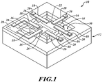
- FIG. 1 is a simplified perspective view of a temperature regulated circuit 10 according to principles disclosed herein.
- the temperature regulated circuit 10 includes a frame 12, a suspended mass 14, support beams 16, conductive tracks 18, bond pads 20, an integrated circuit 22, a temperature sensor 24, a heater 26, and a controller 28.
- the frame 12 provides a support structure for suspending the suspended mass 14.
- the frame 12 is rectangular; however, the frame 12 may have any shape.
- the frame 12 includes an opening 30 and the controller 28. The controller 28 will be discussed in further detail below.
- the suspended mass 14 provides a thermally isolated substrate.
- the suspended mass 14 is positioned in the opening 30 of the frame 12 and is suspended from the frame 12.
- the suspended mass 14 has the same rectangular shape as the frame 12; however, the suspended mass 14 may have any shape.
- the suspended mass 14 has a thickness that is smaller than the thickness of the frame 12 to prevent the suspended mass 14 from contacting a surface below the suspended mass 14, e.g., as shown in Figure 3B .
- the suspended mass 14 includes the integrated circuit 22, the temperature sensor 24, and the heater 26. The integrated circuit 22, the temperature sensor 24, and the heater 26 will be discussed in further detail below.
- the support beams 16 couple the suspended mass 14 to the frame 12.
- the support beams 16 space the suspended mass 14 from the frame 12 on each side of the suspended mass 14 to increase the thermal isolation of the suspended mass 14.
- each of the support beams 16 have a width substantially smaller than a width of the suspended mass 14.
- the support beams 16 are made of a thermally insulating material, such as silicon dioxide, to minimize heat dissipation through the support beams 16.
- the temperature regulated circuit 10 may include any number of support beams.
- the temperature regulated circuit 10 includes four support beams with one support beam on each side of the suspended mass 14.
- the temperature regulated circuit 10 includes more than six support beams to accommodate additional conductive tracks.
- the conductive tracks 18 provide electrical connections between circuitry on the suspended mass 14 and circuitry or bond pads on the frame 12. Particularly, as shown in Figure 1 , the conductive tracks 18 couple the integrated circuit 22 and the heater 26 to bond pads 20, and couple the temperature sensor and the heater 26 to the controller 28. In a preferred embodiment, each of the conductive tracks 18 is formed on a respective support beam such that there is an equal number of conductive tracks 18 and support beams 16. In another embodiment, a plurality of conductive tracks is formed on a single support beam such that the number of conductive tracks 18 is greater than the number of support beams 16. In a preferred embodiment, the conductive tracks 18 substantially cover the upper surfaces of the support beams 16. For example, as shown in Figure 1 , each of the conductive tracks 18 approximately covers the entire upper surface of the respective support beam 16. As a result, the support beams 16 are strengthened and are able support greater loads on the suspended mass 14.
- the bond pads 20 provide a conductive pad for receiving wire bonds and connecting the bond pads 20 to an external location.
- the bond pads 20 are formed on the frame 12. Namely, each of the bond pads 20 is formed on a portion of a conductive track that is on the frame 12.
- the integrated circuit 22 may be any integrated circuit that would benefit from having a stabilized temperature.
- the integrated circuit 22 may be a reference amplifier, a differential NPN pair, a resistor network that include NiCr or SiCr thin film resistors, or an operational amplifier.
- the temperature sensor 24 is configured to measure the temperature of the integrated circuit 22 and generate a temperature signal that is proportional to the temperature of the integrated circuit 22.
- the temperature sensor 24 is electrically coupled to the controller 28 through one of the conductive tracks 18. Although not shown in Figure 1 , the temperature sensor 24 may also be electrically coupled to a bond pad that is on the frame 12. As will be discussed in further detail below, the temperature sensor 24 provides temperature measurements to the controller 28. In a preferred embodiment the temperature sensor 24 is positioned in close proximity to the integrated circuit 22 to ensure that accurate temperature measurements of the integrated circuit 22 are obtained.
- the heater 26 is configured to heat the integrated circuit 22.
- the heater 26 is electrically coupled to the controller 28 and to one of the bond pads 20 through respective conductive tracks 18.
- the heater 26 is controlled by the controller 28.
- the heater 26 is positioned in close proximity to the integrated circuit 22. As will be discussed in further detail below, positioning the heater 26 closer to the integrated circuit allows the integrated circuit to be heated faster and helps to reduce power consumption.
- the controller 28 is positioned on the frame 12.
- the controller 12 is configured to receive temperature measurements from the temperature sensor 24 and control the heater 26 based on the temperature signals received from the temperature sensor 24.
- the controller 28 receives a temperature signal from the temperature sensor 24, determines whether the temperature signal is below a predetermined threshold, and sends a command to the heater 26 to heat the integrated circuit 22 when the temperature signal is below the predetermined threshold.
- the controller 28 receives a temperature signal from the temperature sensor 24, determines whether the temperature signal exceeds a predetermined threshold, and sends a command to the heater 26 to stop heating the integrated circuit 22 when the temperature signal exceeds the predetermined threshold.
- the controller 28, or an error integrator that controls a voltage to the heater 26, continuously receives temperature signals from the temperature sensor 24, and continuously adjusts the heater 26 until a current temperature signal is equal to a predetermined threshold.
- the size of the suspended mass 14 may be reduced. Namely, the suspended mass 14 may be large enough to accommodate only the integrated circuit 22, the temperature sensor 24, and the heater 26. As will be discussed in further detail below, the minimal size of the suspended mass 14 allows the integrated circuit 22 to be heated faster and helps to reduce power consumption.
- the temperature regulated circuit 10 provides a low power solution to regulate temperature of the integrated circuit 22.
- the integrated circuit 22 is thermally isolated from neighboring surfaces. Further, any heat dissipation through the support beams 16 is minimal as the support beams 16, in a preferred embodiment, is made of a thermally insulating material.
- the heater 26 may be used moderately. As a result, the power needed to regulate the temperature of the integrated is greatly reduced. For example, assuming the temperature regulated circuit 10 has a thermal isolation to ambient of approximately 8000 degrees Celsius per watt, the heater 26 would consume under 5 milliwatts for a regulated temperature of 60 degrees Celsius and an ambient temperature of 25 degrees Celsius.
- positioning the heater 26 on the suspended mass 14 in close proximity to the integrated circuit 22 allows the integrated circuit 22 to be heated faster. As a result, the heater 26 may be powered on for shorter periods of time and power may be conserved.
- positioning the controller 28 on the frame, instead of the suspended mass allows the size of the suspended mass 14 to be scaled down. Accordingly, the suspended mass 14 may be heated faster as a smaller mass is heated faster than a larger mass. Thus, the heater 26 may be powered on for shorter periods of time and power may be conserved.
- the integrated circuit 22 may be used in hand-held instruments that have a limited power source.
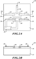
- Figures 2A to 3B are plan views and cross-sectional views illustrating steps of a method for fabricating the temperature regulated circuit 10 according to principles disclosed herein.
- Figure 2A is a plan view of the temperature regulated circuit 10 at a first step
- Figure 2B is a cross-sectional view of the temperature regulated circuit 10 along the axis shown in Figure 2A
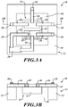
- Figure 3A is a plan view of the temperature regulated circuit 10 at a subsequent step
- Figure 3B is a cross-sectional view of the temperature regulated circuit 10 along the axis shown in Figure 3A .
- the temperature regulated circuit 10 includes a substrate 32, such as a single crystalline silicon wafer, and an insulating layer 34.
- the insulating layer 34 is formed on the substrate 32.
- the insulating layer 34 is made of a thermally insulating material, such as silicon dioxide.
- the integrated circuit 22, the temperature sensor 24, the heater 26, and the controller 28 are fabricated in the substrate 32.
- the integrated circuit 22, the temperature sensor 24, and the heater 26 are fabricated in a central portion of the substrate 32, and the controller 28 is fabricated in a peripheral portion of the substrate 32 that surrounds the central portion.
- the temperature sensor 24 and the heater 26 are positioned in close proximity to the integrated circuit 22.
- the integrated circuit 22, the temperature sensor 24, the heater 26, and the controller 28 may be fabricated in the substrate 32 using techniques known or later developed.
- the integrated circuit 22 may be fabricated using a dielectrically isolated process.
- the components of the integrated circuit 22, the temperature sensor 24, the heater 26, and the controller 28 are not shown in Figure 2B for simplicity reasons.
- the conductive tracks 18 are formed on the insulating layer 34. As previously discussed, the conductive tracks 18 provide electrical connections between circuitry positioned in the central portion of the substrate 32 and bond pads and circuitry positioned in the peripheral portion of the substrate 32. For example, the conductive tracks 18 may couple the integrated circuit 22 and the temperature sensor 24 to bond pads 20, and couple the heater 26 to the controller 28. As shown in Figure 2B , the conductive tracks are formed through the insulating layer 34 to connect to the integrated circuit 22.
- the bond pads 20 are formed on respective conductive tracks 18.
- the bond pads 20 are formed on portions of the conductive tracks 18 that are located on the peripheral portion of the substrate 32.
- portions of the substrate 32 and the insulating layer 34 are removed to form the opening 30 and create the frame 12 and the suspended mass 14.
- portions of the substrate 32 are removed such that the suspended mass 14 has a thickness that is smaller than the thickness of the frame 12 to prevent the suspended mass 14 from contacting a surface below the suspended mass 14.
- Portions of the insulating layer 32 are removed to create the support beams 16. As previously discussed, the support beams 16 suspend the suspended mass 14 from the frame 12. Portions of the substrate 32 and the insulating layer 34 may be removed by using techniques known or later developed. For example, deep reactive-ion etching (DRIE) may be used to etch the substrate 32 and the insulating 34.
- DRIE deep reactive-ion etching
- the temperature regulated circuit 10 is fabricated using a buried oxide (BOX) wafer, instead of the substrate 32 and the insulating layer 34.
- BOX buried oxide
- the integrated circuit 22, the temperature sensor 24, and the heater 26 is fabricated in a central portion of the BOX wafer, and the controller 28 is fabricated in a peripheral portion of the BOX wafer.
- the BOX wafer is micro machined to form the frame 12 and the suspended mass 14.
- the BOX wafer may be etched from the top and bottom using a combination of wet etching or DRIE, or a combination of both.
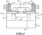
- FIG. 4 is a cross-sectional view of the temperature regulated circuit 10 including wafer-level packaging according principles disclosed herein.
- the wafer-level packaging includes a first wafer 36 and a second wafer 38.
- the temperature regulated circuit 10 is positioned on the first wafer 36.
- the frame 12 is positioned on an upper surface of the first wafer 36.
- the upper surface of the first wafer 36 is spaced from the lower surface of the suspended mass 14 to minimize heat dissipation from the integrated circuit 22 to the first wafer 36.
- the second wafer 38 is positioned on the temperature regulated circuit 10.
- the second wafer 38 includes a cavity 46.
- the cavity 46 spaces the lower surface of the second wafer 38 from the upper surface of the suspended mass 14 to minimize heat dissipation from the integrated circuit 22 to the second wafer 38.
- the second wafer 38 also includes micro-vias 40.
- Each of the micro-vias 40 includes conductive material 44 and a dielectric layer 42 that lines the trench walls of the micro-via.
- Each of the micro-vias 40 is coupled to a respective conductive track 18.
- the micro-vias 40 and the conductive tracks 18 together provide electrical connections between circuity on the suspended mass 14 and circuitry or bond pads 20 on the upper surface of the second wafer 38.
- the first wafer 36, the second wafer 38, and the frame 12 form a chamber 48 for the integrated circuit 22.
- the chamber 48 ensures that the integrated circuit 22 does not contact any neighboring surfaces and dissipate heat.
- the chamber is evacuated or filled with a gas, such as nitrogen, to further improve thermal insulation of the integrated circuit 22.
- a gas such as nitrogen
- the utilization of wafer-level packaging may reduce packing cost and size of the temperature regulated circuit 10.
- the first wafer 36 and the second wafer 38 may include additional integrated circuits.
- the controller 28 is formed in the second wafer 38, instead of the frame 12, and connected to at least one of the micro-vias 40 for electrical coupling the temperature sensor 24 and the heater 26 on the suspended mass 14
- the wafer-level packaging results in increased thermal resistance of the integrated circuit 22 and further reduces the power needed to regulate the temperature of the integrated circuit 22.
- FIG. 5 is a cross-sectional view of the temperature regulated circuit 10 in a hermetic vacuum package 50 according to principles disclosed herein.
- the hermetic vacuum package 50 includes a base 52 and a lid 54.
- the temperature regulated circuit 10 is positioned on the base 52.
- the base 52 is ceramic substrate.
- the lid 54 is coupled to the base 52 and encapsulates the temperature regulated circuit 10.
- the base 52 and the lid 54 form a chamber 56. Similar to the chamber 48, the chamber 56 ensures that the integrated circuit 22 does not contact any neighboring surfaces and dissipate heat.
- the chamber is evacuated or filled with a gas, such as nitrogen, to improve thermal insulation of the integrated circuit 22.
- the hermetic vacuum package 50 may also include wire bonds that are connected to the bond pads 20 to a location outside of the hermetic vacuum package 50.
- the hermetic vacuum package results in increased thermal resistance of the integrated circuit 22 and further reduces the power needed to regulate the temperature of the integrated circuit 22.
- the temperature regulated circuit 10 disclosed herein results in a low power solution for temperature regulation of the integrated circuit 22. Reducing the power needed to regulate the temperature of the integrated circuit 22 increases the potential applications for precision integrated circuits. For instance, the integrated circuit 22 may be used in hand-held instruments that have a limited power source.
- Examples provide a device, comprising a frame having an opening, a controller on the frame, a plurality of support beams made of thermally insulating material, a suspended mass positioned in the opening of the frame, the suspended mass being coupled to the frame by the plurality of support beams, an integrated circuit, a temperature sensor, and a heater on the suspended mass, a first conductive track on a first support beam of the plurality of support beams, the first conductive track electrically coupled to the integrated circuit, the temperature sensor, or the heater.
- Some examples further comprise a second conductive track on a second support beam of the plurality of support beams, the second conductive track electrically coupled to the controller and to the temperature sensor or the heater.
- the controller is configured to receive temperature measurements from the temperature sensor and control the heater based on the temperature measurements.
- Some examples further comprise a first wafer, the frame positioned on the first wafer, and a second wafer overlying the frame and the suspended mass, the suspended mass being spaced from the first and second wafers.
- the first wafer, and the second wafer form a chamber around the suspended mass.
- the chamber is evacuated.
- Some examples further comprise a conductive via formed through the second wafer, the conductive via being electrically coupled to the first conductive track.
- Some examples further comprise a ceramic base, the frame being positioned on the ceramic base, and a lid coupled to the ceramic base, the lid and the ceramic base forming a chamber around the suspended mass.
- Some examples further comprise a bond pad on the frame, the first conductive track being electrically coupled to the bond pad.
- Examples provide a device, comprising a substrate including a first portion having an opening, and a second portion positioned in the opening and spaced from the first portion, a controller on the first portion of the substrate, an integrated circuit, a temperature sensor, and a heater on the second portion of the substrate, an insulating layer on the first and second portions of the substrate, the insulating layer coupling the first and second portions of the substrate to each other, and a first conductive track on the insulating layer, the first conductive track being electrically coupled to the integrated circuit, the temperature sensor, or the heater.
- Some examples further comprise a second conductive track on the insulating layer, the second conductive track electrically coupled to the controller and to the temperature sensor or the heater.
- the controller is configured to receive temperature measurements from the temperature sensor and control the heater based on the temperature measurements.
- Some examples further comprise first and second wafers, the substrate being positioned between the first and second wafers.
- Some examples further comprise a hermetic vacuum package, the substrate being positioned inside of the hermetic vacuum package.
- Some examples further comprise a bond pad on the first portion of the substrate, the bond pad electrically coupled to the first conductive track.
- Examples provide a method, comprising fabricating a controller on a peripheral component of a semiconductor die, fabricating an integrated circuit, a temperature sensor, and a heater element on a central component of the semiconductor die, the peripheral component surrounding the central component, and suspending the central component from the peripheral component by removing portions of the semiconductor die that is between the peripheral component and the central component.
- Some examples further comprise forming a conductive track on the semiconductor die, the conductive track electrically coupling a bond pad on the peripheral component of the semiconductor die to the integrated circuit, the temperature sensor, or the heater element.
- Some examples further comprise positioning the semiconductor die on a first wafer, and positioning a second wafer on the semiconductor die, the first and second wafers being spaced from the central component of the semiconductor die, the peripheral component of the semiconductor die, the first wafer, and the second wafer forming a chamber.
- Some examples further comprise evacuating the chamber.
- Some examples further comprise positioning the semiconductor die in a hermetic vacuum package.
Landscapes
- Cooling Or The Like Of Semiconductors Or Solid State Devices (AREA)
- Pressure Sensors (AREA)
- Container, Conveyance, Adherence, Positioning, Of Wafer (AREA)
- Engineering & Computer Science (AREA)
- Automation & Control Theory (AREA)
- Manufacturing & Machinery (AREA)
Applications Claiming Priority (1)
| Application Number | Priority Date | Filing Date | Title |
|---|---|---|---|
| US15/099,341 US9607913B1 (en) | 2016-04-14 | 2016-04-14 | Low power, temperature regulated circuit for precision integrated circuits |
Publications (2)
| Publication Number | Publication Date |
|---|---|
| EP3232745A1 EP3232745A1 (en) | 2017-10-18 |
| EP3232745B1 true EP3232745B1 (en) | 2020-06-24 |
Family
ID=58360120
Family Applications (1)
| Application Number | Title | Priority Date | Filing Date |
|---|---|---|---|
| EP17166640.7A Active EP3232745B1 (en) | 2016-04-14 | 2017-04-13 | Low power, temperature regulated circuit for precision integrated circuits |
Country Status (4)
| Country | Link |
|---|---|
| US (1) | US9607913B1 (enExample) |
| EP (1) | EP3232745B1 (enExample) |
| JP (1) | JP6809973B2 (enExample) |
| CN (1) | CN107301985B (enExample) |
Families Citing this family (2)
| Publication number | Priority date | Publication date | Assignee | Title |
|---|---|---|---|---|
| DE102019125963A1 (de) * | 2019-09-26 | 2021-04-01 | Schott Ag | Hermetisch verschlossene Glasumhäusung |
| US12500133B2 (en) | 2022-04-01 | 2025-12-16 | Fluke Corporation | Structure, system and method for a temperature regulated electrical device |
Family Cites Families (6)
| Publication number | Priority date | Publication date | Assignee | Title |
|---|---|---|---|---|
| DE4340583A1 (de) * | 1993-11-29 | 1995-06-01 | Krautkraemer Gmbh | Temperaturstabilisierter Hybridschaltkreis |
| DE19748005A1 (de) * | 1997-10-30 | 1999-05-20 | Siemens Ag | Anordnung zum Übertragen von elektrischen Signalen zwischen einem auf einer Trägerplatte thermisch isoliertem Modul und angrenzenden Nachbarmodulen |
| US7484411B2 (en) * | 2007-01-30 | 2009-02-03 | Hewlett-Packard Development Company, L.P. | Three phase capacitance-based sensing and actuation |
| US8049326B2 (en) * | 2007-06-07 | 2011-11-01 | The Regents Of The University Of Michigan | Environment-resistant module, micropackage and methods of manufacturing same |
| US7821346B2 (en) * | 2007-08-24 | 2010-10-26 | Cts Corporation | Ovenized oscillator |
| US20100180681A1 (en) * | 2009-01-22 | 2010-07-22 | Honeywell International Inc. | System and method for increased flux density d'arsonval mems accelerometer |
-
2016
- 2016-04-14 US US15/099,341 patent/US9607913B1/en active Active
-
2017
- 2017-04-11 JP JP2017078206A patent/JP6809973B2/ja active Active
- 2017-04-13 EP EP17166640.7A patent/EP3232745B1/en active Active
- 2017-04-14 CN CN201710243779.3A patent/CN107301985B/zh active Active
Non-Patent Citations (1)
| Title |
|---|
| None * |
Also Published As
| Publication number | Publication date |
|---|---|
| CN107301985A (zh) | 2017-10-27 |
| CN107301985B (zh) | 2022-08-30 |
| EP3232745A1 (en) | 2017-10-18 |
| JP2017191102A (ja) | 2017-10-19 |
| JP6809973B2 (ja) | 2021-01-06 |
| US9607913B1 (en) | 2017-03-28 |
Similar Documents
| Publication | Publication Date | Title |
|---|---|---|
| US12187601B2 (en) | Electronic sensors with sensor die in package structure cavity | |
| CN108269769B (zh) | 具有隔热和温度调节的集成电路 | |
| TWI259547B (en) | Process condition sensing wafer and data analysis system | |
| TWI239319B (en) | Packaging microelectromechanical structures | |
| US6731180B1 (en) | Evacuated hybrid ovenized oscillator | |
| US6452798B1 (en) | Electronic module including a cooling substrate having a fluid cooling circuit therein and related methods | |
| US20250007455A1 (en) | Ovenized MEMS | |
| US20100294051A1 (en) | Process condition sensing wafer and data analysis system | |
| TW202107635A (zh) | 半導體封裝結構 | |
| EP3232745B1 (en) | Low power, temperature regulated circuit for precision integrated circuits | |
| JP2018113430A (ja) | 接点を有する、応力均衡のとれた静電基板キャリア | |
| US20250096774A1 (en) | Electronic package structure | |
| TW201803163A (zh) | 壓電封裝整合式壓力感測裝置 | |
| US20180131324A1 (en) | High-Efficiency Ovenized Oscillator | |
| CN101375394B (zh) | 减小翘曲的封装设计 | |
| US12500133B2 (en) | Structure, system and method for a temperature regulated electrical device | |
| JP2021190603A (ja) | 保持装置 | |
| CN107697880B (zh) | 一种基于soi-mems的温控隔振平台及系统 | |
| CN110240114B (zh) | 包括微机电系统和封装该微机电系统的盒子的电子系统 | |
| CN118367867A (zh) | Mems振荡器及电子设备 | |
| JP5135018B2 (ja) | 恒温型の水晶発振器 | |
| JP2017191102A5 (enExample) | ||
| CN115775762B (en) | Electrostatic chuck with multiple heating area structures | |
| JP2004158547A (ja) | ヒータ | |
| TW201904857A (zh) | 微機電系統元件及其靜電接合方法 |
Legal Events
| Date | Code | Title | Description |
|---|---|---|---|
| PUAI | Public reference made under article 153(3) epc to a published international application that has entered the european phase |
Free format text: ORIGINAL CODE: 0009012 |
|
| STAA | Information on the status of an ep patent application or granted ep patent |
Free format text: STATUS: THE APPLICATION HAS BEEN PUBLISHED |
|
| AK | Designated contracting states |
Kind code of ref document: A1 Designated state(s): AL AT BE BG CH CY CZ DE DK EE ES FI FR GB GR HR HU IE IS IT LI LT LU LV MC MK MT NL NO PL PT RO RS SE SI SK SM TR |
|
| AX | Request for extension of the european patent |
Extension state: BA ME |
|
| STAA | Information on the status of an ep patent application or granted ep patent |
Free format text: STATUS: REQUEST FOR EXAMINATION WAS MADE |
|
| 17P | Request for examination filed |
Effective date: 20180406 |
|
| RBV | Designated contracting states (corrected) |
Designated state(s): AL AT BE BG CH CY CZ DE DK EE ES FI FR GB GR HR HU IE IS IT LI LT LU LV MC MK MT NL NO PL PT RO RS SE SI SK SM TR |
|
| GRAP | Despatch of communication of intention to grant a patent |
Free format text: ORIGINAL CODE: EPIDOSNIGR1 |
|
| STAA | Information on the status of an ep patent application or granted ep patent |
Free format text: STATUS: GRANT OF PATENT IS INTENDED |
|
| RIC1 | Information provided on ipc code assigned before grant |
Ipc: H05K 1/14 20060101ALI20200117BHEP Ipc: H01L 21/52 20060101ALI20200117BHEP Ipc: H01L 23/16 20060101ALI20200117BHEP Ipc: H01L 23/053 20060101ALI20200117BHEP Ipc: H01L 23/482 20060101ALI20200117BHEP Ipc: H05K 1/02 20060101AFI20200117BHEP |
|
| INTG | Intention to grant announced |
Effective date: 20200207 |
|
| GRAS | Grant fee paid |
Free format text: ORIGINAL CODE: EPIDOSNIGR3 |
|
| GRAA | (expected) grant |
Free format text: ORIGINAL CODE: 0009210 |
|
| STAA | Information on the status of an ep patent application or granted ep patent |
Free format text: STATUS: THE PATENT HAS BEEN GRANTED |
|
| AK | Designated contracting states |
Kind code of ref document: B1 Designated state(s): AL AT BE BG CH CY CZ DE DK EE ES FI FR GB GR HR HU IE IS IT LI LT LU LV MC MK MT NL NO PL PT RO RS SE SI SK SM TR |
|
| REG | Reference to a national code |
Ref country code: GB Ref legal event code: FG4D |
|
| REG | Reference to a national code |
Ref country code: CH Ref legal event code: EP |
|
| REG | Reference to a national code |
Ref country code: DE Ref legal event code: R096 Ref document number: 602017018548 Country of ref document: DE |
|
| REG | Reference to a national code |
Ref country code: AT Ref legal event code: REF Ref document number: 1285218 Country of ref document: AT Kind code of ref document: T Effective date: 20200715 |
|
| REG | Reference to a national code |
Ref country code: IE Ref legal event code: FG4D |
|
| PG25 | Lapsed in a contracting state [announced via postgrant information from national office to epo] |
Ref country code: SE Free format text: LAPSE BECAUSE OF FAILURE TO SUBMIT A TRANSLATION OF THE DESCRIPTION OR TO PAY THE FEE WITHIN THE PRESCRIBED TIME-LIMIT Effective date: 20200624 Ref country code: GR Free format text: LAPSE BECAUSE OF FAILURE TO SUBMIT A TRANSLATION OF THE DESCRIPTION OR TO PAY THE FEE WITHIN THE PRESCRIBED TIME-LIMIT Effective date: 20200925 Ref country code: NO Free format text: LAPSE BECAUSE OF FAILURE TO SUBMIT A TRANSLATION OF THE DESCRIPTION OR TO PAY THE FEE WITHIN THE PRESCRIBED TIME-LIMIT Effective date: 20200924 Ref country code: FI Free format text: LAPSE BECAUSE OF FAILURE TO SUBMIT A TRANSLATION OF THE DESCRIPTION OR TO PAY THE FEE WITHIN THE PRESCRIBED TIME-LIMIT Effective date: 20200624 Ref country code: LT Free format text: LAPSE BECAUSE OF FAILURE TO SUBMIT A TRANSLATION OF THE DESCRIPTION OR TO PAY THE FEE WITHIN THE PRESCRIBED TIME-LIMIT Effective date: 20200624 |
|
| REG | Reference to a national code |
Ref country code: LT Ref legal event code: MG4D |
|
| PG25 | Lapsed in a contracting state [announced via postgrant information from national office to epo] |
Ref country code: LV Free format text: LAPSE BECAUSE OF FAILURE TO SUBMIT A TRANSLATION OF THE DESCRIPTION OR TO PAY THE FEE WITHIN THE PRESCRIBED TIME-LIMIT Effective date: 20200624 Ref country code: HR Free format text: LAPSE BECAUSE OF FAILURE TO SUBMIT A TRANSLATION OF THE DESCRIPTION OR TO PAY THE FEE WITHIN THE PRESCRIBED TIME-LIMIT Effective date: 20200624 Ref country code: RS Free format text: LAPSE BECAUSE OF FAILURE TO SUBMIT A TRANSLATION OF THE DESCRIPTION OR TO PAY THE FEE WITHIN THE PRESCRIBED TIME-LIMIT Effective date: 20200624 Ref country code: BG Free format text: LAPSE BECAUSE OF FAILURE TO SUBMIT A TRANSLATION OF THE DESCRIPTION OR TO PAY THE FEE WITHIN THE PRESCRIBED TIME-LIMIT Effective date: 20200924 |
|
| REG | Reference to a national code |
Ref country code: NL Ref legal event code: MP Effective date: 20200624 |
|
| REG | Reference to a national code |
Ref country code: AT Ref legal event code: MK05 Ref document number: 1285218 Country of ref document: AT Kind code of ref document: T Effective date: 20200624 |
|
| PG25 | Lapsed in a contracting state [announced via postgrant information from national office to epo] |
Ref country code: AL Free format text: LAPSE BECAUSE OF FAILURE TO SUBMIT A TRANSLATION OF THE DESCRIPTION OR TO PAY THE FEE WITHIN THE PRESCRIBED TIME-LIMIT Effective date: 20200624 Ref country code: NL Free format text: LAPSE BECAUSE OF FAILURE TO SUBMIT A TRANSLATION OF THE DESCRIPTION OR TO PAY THE FEE WITHIN THE PRESCRIBED TIME-LIMIT Effective date: 20200624 |
|
| PG25 | Lapsed in a contracting state [announced via postgrant information from national office to epo] |
Ref country code: SM Free format text: LAPSE BECAUSE OF FAILURE TO SUBMIT A TRANSLATION OF THE DESCRIPTION OR TO PAY THE FEE WITHIN THE PRESCRIBED TIME-LIMIT Effective date: 20200624 Ref country code: PT Free format text: LAPSE BECAUSE OF FAILURE TO SUBMIT A TRANSLATION OF THE DESCRIPTION OR TO PAY THE FEE WITHIN THE PRESCRIBED TIME-LIMIT Effective date: 20201026 Ref country code: ES Free format text: LAPSE BECAUSE OF FAILURE TO SUBMIT A TRANSLATION OF THE DESCRIPTION OR TO PAY THE FEE WITHIN THE PRESCRIBED TIME-LIMIT Effective date: 20200624 Ref country code: IT Free format text: LAPSE BECAUSE OF FAILURE TO SUBMIT A TRANSLATION OF THE DESCRIPTION OR TO PAY THE FEE WITHIN THE PRESCRIBED TIME-LIMIT Effective date: 20200624 Ref country code: RO Free format text: LAPSE BECAUSE OF FAILURE TO SUBMIT A TRANSLATION OF THE DESCRIPTION OR TO PAY THE FEE WITHIN THE PRESCRIBED TIME-LIMIT Effective date: 20200624 Ref country code: CZ Free format text: LAPSE BECAUSE OF FAILURE TO SUBMIT A TRANSLATION OF THE DESCRIPTION OR TO PAY THE FEE WITHIN THE PRESCRIBED TIME-LIMIT Effective date: 20200624 Ref country code: AT Free format text: LAPSE BECAUSE OF FAILURE TO SUBMIT A TRANSLATION OF THE DESCRIPTION OR TO PAY THE FEE WITHIN THE PRESCRIBED TIME-LIMIT Effective date: 20200624 |
|
| PG25 | Lapsed in a contracting state [announced via postgrant information from national office to epo] |
Ref country code: PL Free format text: LAPSE BECAUSE OF FAILURE TO SUBMIT A TRANSLATION OF THE DESCRIPTION OR TO PAY THE FEE WITHIN THE PRESCRIBED TIME-LIMIT Effective date: 20200624 Ref country code: SK Free format text: LAPSE BECAUSE OF FAILURE TO SUBMIT A TRANSLATION OF THE DESCRIPTION OR TO PAY THE FEE WITHIN THE PRESCRIBED TIME-LIMIT Effective date: 20200624 Ref country code: IS Free format text: LAPSE BECAUSE OF FAILURE TO SUBMIT A TRANSLATION OF THE DESCRIPTION OR TO PAY THE FEE WITHIN THE PRESCRIBED TIME-LIMIT Effective date: 20201024 |
|
| REG | Reference to a national code |
Ref country code: DE Ref legal event code: R097 Ref document number: 602017018548 Country of ref document: DE |
|
| PG25 | Lapsed in a contracting state [announced via postgrant information from national office to epo] |
Ref country code: DK Free format text: LAPSE BECAUSE OF FAILURE TO SUBMIT A TRANSLATION OF THE DESCRIPTION OR TO PAY THE FEE WITHIN THE PRESCRIBED TIME-LIMIT Effective date: 20200624 |
|
| PLBE | No opposition filed within time limit |
Free format text: ORIGINAL CODE: 0009261 |
|
| STAA | Information on the status of an ep patent application or granted ep patent |
Free format text: STATUS: NO OPPOSITION FILED WITHIN TIME LIMIT |
|
| 26N | No opposition filed |
Effective date: 20210325 |
|
| PG25 | Lapsed in a contracting state [announced via postgrant information from national office to epo] |
Ref country code: SI Free format text: LAPSE BECAUSE OF FAILURE TO SUBMIT A TRANSLATION OF THE DESCRIPTION OR TO PAY THE FEE WITHIN THE PRESCRIBED TIME-LIMIT Effective date: 20200624 |
|
| PG25 | Lapsed in a contracting state [announced via postgrant information from national office to epo] |
Ref country code: MC Free format text: LAPSE BECAUSE OF FAILURE TO SUBMIT A TRANSLATION OF THE DESCRIPTION OR TO PAY THE FEE WITHIN THE PRESCRIBED TIME-LIMIT Effective date: 20200624 |
|
| PG25 | Lapsed in a contracting state [announced via postgrant information from national office to epo] |
Ref country code: LU Free format text: LAPSE BECAUSE OF NON-PAYMENT OF DUE FEES Effective date: 20210413 |
|
| REG | Reference to a national code |
Ref country code: BE Ref legal event code: MM Effective date: 20210430 |
|
| PG25 | Lapsed in a contracting state [announced via postgrant information from national office to epo] |
Ref country code: CH Free format text: LAPSE BECAUSE OF NON-PAYMENT OF DUE FEES Effective date: 20210430 Ref country code: LI Free format text: LAPSE BECAUSE OF NON-PAYMENT OF DUE FEES Effective date: 20210430 |
|
| PG25 | Lapsed in a contracting state [announced via postgrant information from national office to epo] |
Ref country code: IE Free format text: LAPSE BECAUSE OF NON-PAYMENT OF DUE FEES Effective date: 20210413 |
|
| PG25 | Lapsed in a contracting state [announced via postgrant information from national office to epo] |
Ref country code: IS Free format text: LAPSE BECAUSE OF FAILURE TO SUBMIT A TRANSLATION OF THE DESCRIPTION OR TO PAY THE FEE WITHIN THE PRESCRIBED TIME-LIMIT Effective date: 20201024 |
|
| PG25 | Lapsed in a contracting state [announced via postgrant information from national office to epo] |
Ref country code: BE Free format text: LAPSE BECAUSE OF NON-PAYMENT OF DUE FEES Effective date: 20210430 |
|
| PG25 | Lapsed in a contracting state [announced via postgrant information from national office to epo] |
Ref country code: HU Free format text: LAPSE BECAUSE OF FAILURE TO SUBMIT A TRANSLATION OF THE DESCRIPTION OR TO PAY THE FEE WITHIN THE PRESCRIBED TIME-LIMIT; INVALID AB INITIO Effective date: 20170413 Ref country code: EE Free format text: LAPSE BECAUSE OF FAILURE TO SUBMIT A TRANSLATION OF THE DESCRIPTION OR TO PAY THE FEE WITHIN THE PRESCRIBED TIME-LIMIT Effective date: 20200624 |
|
| PG25 | Lapsed in a contracting state [announced via postgrant information from national office to epo] |
Ref country code: CY Free format text: LAPSE BECAUSE OF FAILURE TO SUBMIT A TRANSLATION OF THE DESCRIPTION OR TO PAY THE FEE WITHIN THE PRESCRIBED TIME-LIMIT Effective date: 20200624 |
|
| PG25 | Lapsed in a contracting state [announced via postgrant information from national office to epo] |
Ref country code: MK Free format text: LAPSE BECAUSE OF FAILURE TO SUBMIT A TRANSLATION OF THE DESCRIPTION OR TO PAY THE FEE WITHIN THE PRESCRIBED TIME-LIMIT Effective date: 20200624 |
|
| PG25 | Lapsed in a contracting state [announced via postgrant information from national office to epo] |
Ref country code: TR Free format text: LAPSE BECAUSE OF FAILURE TO SUBMIT A TRANSLATION OF THE DESCRIPTION OR TO PAY THE FEE WITHIN THE PRESCRIBED TIME-LIMIT Effective date: 20200624 |
|
| PG25 | Lapsed in a contracting state [announced via postgrant information from national office to epo] |
Ref country code: MT Free format text: LAPSE BECAUSE OF FAILURE TO SUBMIT A TRANSLATION OF THE DESCRIPTION OR TO PAY THE FEE WITHIN THE PRESCRIBED TIME-LIMIT Effective date: 20200624 |
|
| PGFP | Annual fee paid to national office [announced via postgrant information from national office to epo] |
Ref country code: DE Payment date: 20250428 Year of fee payment: 9 |
|
| PGFP | Annual fee paid to national office [announced via postgrant information from national office to epo] |
Ref country code: GB Payment date: 20250422 Year of fee payment: 9 |
|
| PGFP | Annual fee paid to national office [announced via postgrant information from national office to epo] |
Ref country code: FR Payment date: 20250424 Year of fee payment: 9 |