EP3232153B1 - Tragbares präzisionsscangerät - Google Patents
Tragbares präzisionsscangerät Download PDFInfo
- Publication number
- EP3232153B1 EP3232153B1 EP17166074.9A EP17166074A EP3232153B1 EP 3232153 B1 EP3232153 B1 EP 3232153B1 EP 17166074 A EP17166074 A EP 17166074A EP 3232153 B1 EP3232153 B1 EP 3232153B1
- Authority
- EP
- European Patent Office
- Prior art keywords
- camera
- light
- pattern
- dot
- data
- Prior art date
- Legal status (The legal status is an assumption and is not a legal conclusion. Google has not performed a legal analysis and makes no representation as to the accuracy of the status listed.)
- Active
Links
Images


Classifications
-
- G—PHYSICS
- G01—MEASURING; TESTING
- G01B—MEASURING LENGTH, THICKNESS OR SIMILAR LINEAR DIMENSIONS; MEASURING ANGLES; MEASURING AREAS; MEASURING IRREGULARITIES OF SURFACES OR CONTOURS
- G01B11/00—Measuring arrangements characterised by the use of optical techniques
- G01B11/24—Measuring arrangements characterised by the use of optical techniques for measuring contours or curvatures
- G01B11/25—Measuring arrangements characterised by the use of optical techniques for measuring contours or curvatures by projecting a pattern, e.g. one or more lines, moiré fringes on the object
- G01B11/2518—Projection by scanning of the object
-
- G—PHYSICS
- G01—MEASURING; TESTING
- G01B—MEASURING LENGTH, THICKNESS OR SIMILAR LINEAR DIMENSIONS; MEASURING ANGLES; MEASURING AREAS; MEASURING IRREGULARITIES OF SURFACES OR CONTOURS
- G01B11/00—Measuring arrangements characterised by the use of optical techniques
- G01B11/24—Measuring arrangements characterised by the use of optical techniques for measuring contours or curvatures
- G01B11/25—Measuring arrangements characterised by the use of optical techniques for measuring contours or curvatures by projecting a pattern, e.g. one or more lines, moiré fringes on the object
- G01B11/2513—Measuring arrangements characterised by the use of optical techniques for measuring contours or curvatures by projecting a pattern, e.g. one or more lines, moiré fringes on the object with several lines being projected in more than one direction, e.g. grids, patterns
-
- G—PHYSICS
- G01—MEASURING; TESTING
- G01B—MEASURING LENGTH, THICKNESS OR SIMILAR LINEAR DIMENSIONS; MEASURING ANGLES; MEASURING AREAS; MEASURING IRREGULARITIES OF SURFACES OR CONTOURS
- G01B11/00—Measuring arrangements characterised by the use of optical techniques
- G01B11/24—Measuring arrangements characterised by the use of optical techniques for measuring contours or curvatures
- G01B11/25—Measuring arrangements characterised by the use of optical techniques for measuring contours or curvatures by projecting a pattern, e.g. one or more lines, moiré fringes on the object
- G01B11/2545—Measuring arrangements characterised by the use of optical techniques for measuring contours or curvatures by projecting a pattern, e.g. one or more lines, moiré fringes on the object with one projection direction and several detection directions, e.g. stereo
-
- H—ELECTRICITY
- H04—ELECTRIC COMMUNICATION TECHNIQUE
- H04N—PICTORIAL COMMUNICATION, e.g. TELEVISION
- H04N23/00—Cameras or camera modules comprising electronic image sensors; Control thereof
- H04N23/90—Arrangement of cameras or camera modules, e.g. multiple cameras in TV studios or sports stadiums
Definitions
- This disclosure relates generally to scanning, and more specifically to a precision hand-held scanner for measuring surface profiles.
- WO2014/149702A1 discloses a noncontact optical three-dimensional measuring device that includes a first projector, a first camera, a second projector, and a second camera; a processor electrically coupled to the first projector, the first camera, the second projector, and the second camera; and computer readable media which, when executed by the processor, causes the first digital signal to be collected at a first time and the second digital signal to be collected at a second time different than the first time and determines three-dimensional coordinates of a first point on the surface based at least in part on the first digital signal and the first distance and determines three-dimensional coordinates of a second point on the surface based at least in part on the second digital signal and the second distance.
- EP2702354A1 discloses a measuring system for the calculation of dimensions, including area and volume, of objects in various shapes.
- miniature 3D measuring equipment that is suitable for 3D measurements of subcutaneous tumours in mice.
- the measuring system for 3D measurements of objects in various shapes includes a handheld device that has at least 1 camera, 1 projector and a measuring chamber.
- the handheld device may have 2 cameras and a projector and the 3D measurement is based on stereo-vision.
- Said handheld device also has a processor module, a user interface, power supply and a data communication interface, and exchangeable measuring chambers to give the device the necessary flexibility and autonomy to speed up the measurement procedure, and to significantly improve the reproducibility of the measurement.
- FR2950138A1 discloses a method involving calculating a relative rotating component of a scanner between two positions at acquisition instants of a pair of stereoscopic images associated with mottled points from data provided by an inertial unit of the scanner. Coordinates of a characteristic point are determined from the mottled points. A translation component between the mottled points is determined from the coordinates of the characteristic point. Transformation between the rotating component and the translation component is applied to the other mottled point during recycling phase of the mottled points. Also disclosed is a computer program comprising a set of instructions implementing a method for construction of a three-dimensional digital model of a physical surface, and a three-dimensional digitization system comprising a CPU on which the computer program is implemented.
- US2013/188012A1 discloses a surface measurement module for 3D image acquisition of a subject-under-inspection.
- the module having: (a) a casing to house a pattern shifting device having a fixed-pattern optic through which light from a light source is passed, an output of the pattern shifting device being directed at a polarizing beam splitter and the polarized output of the splitter directed through a lens assembly comprising at least one lens element; (b) a reflector to direct the polarized output exiting the lens assembly, to illuminate a surface of the subject-under-inspection; (c) a scattered light illumination off the surface is directed back through the lens assembly for capture by an image sensor; and (d) the casing also housing the polarizing beam splitter, the lens assembly, and the image sensor.
- the output of the fixed-pattern optic comprises a multi-frequency pattern.
- the pattern shifting device may be a linear or rotating type.
- US2012/120412A1 discloses a surface measurement module for 3D triangulation-based image acquisition of a surface-under-inspection and under observation by at least one camera.
- the module having: (a) a casing housing an optical system comprising a plurality of lens elements positioned between a fixed-pattern optic and a light source; (b) an output of said fixed-pattern optic comprising a multi-frequency pattern comprising a plurality of pixels representing at least a first and second superimposed sinusoid projected simultaneously, each of the sinusoids represented by the pixels having a unique temporal frequency and each of the pixels projected to satisfy a specific equation, (c) a shifting element to spatially shift said output of said fixed-pattern optic during projection onto the surface-under-inspection; and (d) a plurality of images captured of said output of said fixed-pattern optic during projection onto the surface-under-inspection are used for the image acquisition.
- US2015/381972A1 discloses using a known projection pattern to make stereo (or other camera-based) depth detection more robust. Dots are detected in captured images and compared to the known projection pattern at different depths, to determine a matching confidence score at each depth.
- the confidence scores may be used as a basis for determining a depth at each dot location, which may be at sub-pixel resolution.
- the confidence scores also may be used as a basis for weights or the like for interpolating pixel depths to find depth values for pixels in between the pixels that correspond to the dot locations.
- DE202012102541U discloses a 3D camera having at least two camera modules, each having an image sensor for generating image data from a monitoring area, with a triangulation unit for calculating a depth map from the image data by means of correlation by application of a stereo algorithm, and by a lighting unit for generating a structured illumination pattern in the surveillance area, characterized in that the triangulation unit is adapted to at least reference image data of the illumination pattern train in a known distance and in operation determine distances by correlating the recorded image data with the reference image data to supplement the depth map determined by the stereo algorithm with areas in which the viewing areas of the camera modules do not overlap one another, but the structured illumination pattern in the viewing area of at least one camera module is located.
- the projected pattern of light may comprise a dot pattern.
- the first data may comprise first pixel data associated with each dot of the projected pattern of light.
- the second data comprises second pixel data associated with each dot of the projected pattern of light.
- the one or more processors may be configured to determine a location of each dot of the dot pattern using the first pixel data and the second pixel data.
- the one or more processors may further be configured to measure profiles of the surface based on the relative dot locations in a three-dimensional "3D" space.
- a method including projecting, by an LED projector, a pattern of light according to an etched pattern on a lens onto a surface by transmitting light through the lens.
- the method further includes capturing, by a first camera, first data associated with the projected pattern of light and capturing, by a second camera, second data associated with the projected pattern of light.
- the method comprises measuring, by one or more processors, profiles of the surface using the first data captured by the first camera and the second data captured by the second camera, wherein the one or more processors are further-configured to automatically detect a range to the surface and trigger the first camera and the second camera to shutter based on the automatically detected range.
- the hand-held scanner is configured to collect accurate data even when the scanner or object being scanned is in motion. Additionally, in certain embodiments, the hand-held scanner provides high resolution scanning capability in the sub-thousandth range.
- certain embodiments of the present disclosure can be used in a variety of applications where features and surfaces must be measured and analyzed to determine conformance to engineering requirements. For example, some embodiments may be used for corrosion analysis, structural repair verification, and panel-to-panel gap/mismatch analysis. Some embodiments of the hand-held scanner may be used to measure coatings to verify that they have been applied to specific height or thickness requirements, such as on low-observable aircraft applications. For example, some embodiments may be used to accurately measure the area over filled and/or unfilled fasteners relative to the surrounding aircraft surface profiles. The scan data acquired from the hand-held device, in conjunction with developed data analysis software, may quickly scan fasteners and analyze the filled and/or unfilled data profile to verify conformance to specific installation tolerances.
- the hand-held scanner may be used to scan external and/or exposed internal body parts.
- This scanning capability may be coupled with 3D printing technology to create replacement bone sections, analyze tissue and/or organs, create 3D models for prosthetics, and the like.
- FIGURES 1 through 4 where like numbers are used to indicate like and corresponding parts.
- RGB-D Consumer grade Red-Green-Blue-Depth
- structured light metrology grade scanners are limited by the exposure time of the cameras.
- a large opening camera aperture increases the gathered light and reduces the exposure time, which makes the scanner less susceptible to scanner movement errors but also limits the depth of field measurements.
- a smaller opening aperture reduces the gathered light and lengthens the exposure time, which makes the scanner more susceptible to scanner movement errors but expands the depth of field measurements.
- Some structured light scanners use the Fourier fringe pattern principle.
- This method projects a structured pattern (e.g., bars or stripes) on an object to be measured, and one or more cameras, precisely calibrated to a flat surface pattern, may be used to triangulate the distance to each pixel in the camera field of view based on the calibrated relationship between the projector and the one or more cameras.
- This phase shifting pattern takes additional time to accomplish the scan and demands high stability from the scanner and the object to be measured.
- the projector is typically a Digital Light Processing (“DLP”) or similar bulky projector, making this arrangement unsuitable for hand-held operation.
- DLP Digital Light Processing
- These structured light scanning systems are also configured to accept multiple lenses to change the field of view for differing applications.
- the scanner housing must accommodate wider placement of the cameras relative to the projector, creating a scanner head size that cannot be used in limited access areas.
- the scanning system may require support stands, counter-balancers, or two-handed operation.
- this phase shifting approach also collects excessive data, which adds to processing time and data storage requirements. For example, a structured light scanning system that utilizes a four megapixel camera and collects and analyzes data from each camera pixel (i.e., four million points) is considered excessive for a four-inch by four-inch field of view.
- some embodiments of the present disclosure include a hand-held scanning device with a shallow depth of field for limited, close-in access to the subject being measured. Additionally, a large/fast opening aperture may be utilized to reduce or eliminate measurement errors due to scanner or subject movement during data capture.
- the invention provides an etched lens with an LED projector to project a pattern on the subject being measured, which enables a drastic reduction in the physical size of the scanning system and allows maneuverability within limited spaces, such as an interior aircraft structure.
- the LED projector can be used in multiple ways. As an example, when measuring more reflective objects, the LED projector may be continuously illuminated and the camera lens pulsed to take the data capture of the subject surface. As another example, when measuring less reflective objects, such as darker surfaces typical of composites or coatings, the LED projector can be fired in synchronization with the camera lens. This results in a pulse (e.g., strobe) of brighter light than when in the continuous mode, better illuminating the object for data capture.
- a pulse e.g., strobe
- a further advantage of continuously projecting the pattern of light onto a surface is that, by analyzing the structured pattern during scanner positioning, the invention auto detects a range to the surface and triggers the camera shutter when an optimal range to the surface is achieved.
- the scanner apparatus may be turned on via a trigger mechanism, and the scanning apparatus may then be moved toward an object to be measured.
- the camera's shutter may automatically trigger, capturing the data within the scene. For instance, the camera's shutter may automatically trigger upon the detection of a pre-determined number of dots within a field of view.
- FIGURES 1-4 provide additional details relating to a precision hand-held scanner.
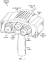
- FIGURE 1 illustrates a hand-held scanner 100, according to certain embodiments.
- hand-held scanner 100 comprises a first camera 110, a second camera 120, an LED projector 130, an etched lens 140, a connector 150, a housing 160, a handle 170, and a mounting base 180.
- hand-held scanner 100 is a single hand-held, motion independent, high resolution scanner.
- First camera 110 is any camera configured to capture data.
- first camera 110 is a 5 megapixel ("MP"), Point Gray Camera.
- first camera 110 may comprise a resolution higher or lower than 5MP.
- first camera 110 may be a 12MP camera.
- first camera 110 may be a 3.2MP camera.
- first camera 110 comprises an aperture configured to reduce or eliminate measurement errors due to movement of hand-held scanner 100 and/or due to movement of the subject during data capture.
- second camera 120 is any camera configured to capture data.
- second camera 120 is a 5 MP, Point Gray Camera.
- second camera 120 may comprise a resolution higher or lower than 5MP.
- second camera 120 may be a 12MP camera.
- second camera 120 may be a 3.2MP camera.
- second camera 120 comprises an aperture configured to reduce or eliminate measurement errors due to movement of hand-held scanner 100 and/or due to movement of the subject during data capture.
- first camera 110 and second camera 120 are identical cameras.
- LED projector 130 is any projector configured to project a pattern of light onto a surface.
- LED projector 130 may project a light continuously during the scanning process.
- LED projector may be an LED strobe light configured to fire in synchronization with one or more features (e.g., first camera 110 and/or second camera 120) of hand-held scanner 100.
- LED projector 130 is a Smart Vision Lights SP30 Series LED projector configured to operate in continuous or strobe mode.
- Etched lens 140 is any lens comprising an etched pattern.
- etched lens 140 is configured to create a structured pattern on a surface being measured.
- the structured pattern may comprise a grid of dots.
- structured pattern of etched lens 140 may comprise a grid of 100,000 dots or less.
- structured pattern of etched lens 140 may comprise a 51 by 51 grid of dots.
- etched lens 140 physically attaches to LED projector 130.
- Connector 150 is any connector operable to couple hand-held scanner 100 to a source (e.g., a power source and/or a computer system).
- a source e.g., a power source and/or a computer system.
- connector 150 is a coaxial cable connector operable to electrically couple hand-held scanner 100 to a computer system, such as computer system 210 discussed below.
- connector 150 may be configured to connect hand-held scanner 100 to a power source, such as an outlet.
- hand-held scanner 100 may comprise more than one connector 150 (e.g., a power connector and a computer system connector).
- hand-held scanner 100 may utilize an integral battery for a power source.
- hand-held scanner 100 may comprise wireless data transfer technology that enables hand-held scanner to communicate with computer system 210 via a BLUETOOTH or WI-FI network.
- wireless data transfer technology of hand-held scanner 100 may facilitate the transfer of data between hand-held scanner 100 and computer system 210.
- housing 160 is any housing configured to enclose, at least partially, first camera 110, second camera 120, and LED projector 130.
- Housing 160 may be made of any material suitable to enclose first camera 110, second camera 120, and LED projector 130.
- housing 160 may be made of plastic.
- housing 160 comprises one or more openings.
- housing 160 may comprise an opening for camera 110, camera 120, and LED projector 130.
- housing 160 may comprise one or more vents that allow air to flow through the scanner to reduce heat.
- Handle 170 is any handle that assists a user with holding hand-held scanner 100.
- handle 170 may be a pistol grip handle made of plastic, rubber, and metal.
- handle 170 attaches to one or more components of hand-held scanner 100.
- handle 170 attaches to the underside of mounting base 180 of hand-held scanner 100, wherein first camera 110, second camera 120, LED projector 130, and housing 160 attach to an upper side of mounting base 180.
- mounting base 180 of hand-held scanner 100 and handle 170 are manufactured as a single component.
- mounting base 180 of hand-held scanner 100 and handle 170 may be manufactured as two separate components, wherein handle 170 physically connects to mounting base 180.
- Mounting base 180 is any base that allows for mounting of components of hand-held scanner 100.
- mounting base 180 may be a mounting rail.
- mounting base 180 is constructed of a thermally stable material such as graphite composite.
- a thermally stable mounting base maintains a stable, fixed, unchanging physical relationship between first camera 110, second camera 120, LED projector 130, and etched lens 140 during changes in surrounding elements.
- a thermally stable mounting base may maintain the spatial relationship between first camera 110 and second camera 120 during changes in temperature caused by environmental conditions and/or heating of components internal to hand-held scanner 100.
- mounting base 180 attaches to one or more components of hand-held scanner 100.
- handle 170 attaches to an underside of mounting base 180 of hand-held scanner 100, wherein first camera 110, second camera 120, LED projector 130, and housing 160 attach to an upper side of mounting base 180.
- the mounting base 180 of hand-held scanner 100 and handle 170 are manufactured as a single component.
- the mounting base 180 of hand-held scanner 100 and handle 170 may be manufactured as two separate components, wherein handle 170 physically connects to the mounting base 180.
- FIGURE 2 illustrates a system 200 for measuring surface profiles, according to certain embodiments.
- system 200 comprises hand-held scanner 100 of FIGURE 1 and computer system 210.
- Computer system 210 includes one or more processors 212, one or more memory units 214, and/or one or more interfaces 216.
- Computer system 210 may be external to hand-held scanner 100.
- hand-held scanner may comprise computer system 210, or one or more components thereof.
- individual components of hand-held scanner 100 e.g., LED projector 130, first camera 110, and second camera 120
- a certain embodiment of computer system 210 is described in further detail below in FIGURE 4 .
- LED projector 130 is configured to project a pattern of light onto a surface 220.
- LED projector 130 is configured to project a pattern of light according to an etched pattern of lens 140 by transmitting light through lens 140.
- the projected pattern of light may comprise a dot pattern of 100,000 dots or less within a four-inch by four-inch maximum field of view (e.g., field of view 220).
- the projected pattern of light may comprise a 51 by 51 shadow mask grid of points within a three-inch by three-inch field of view.
- system 200 of FIGURE 2 is scalable.
- the projected pattern of light may comprise a 51 by 51 shadow mask grid of points within a one-meter by one-meter field of view.
- the projected pattern of light may comprise a 51 by 51 shadow mask grid of points within a two-inch by two-inch field of view.
- the degree of accuracy of the measured profiles depends on the dot pattern relative to its field of view. For example, a 51 by 51 dot pattern projected onto a three-inch by three-inch field of view will have a higher accuracy than a 51 by 51 dot pattern projected onto a one-meter by one meter field of view.
- System 200 further comprises first camera 110 configured to capture first data.
- the first data comprises first pixel data associated with each dot of a projected dot pattern of light.
- the first data may comprise 50 pixels associated with each dot of the projected dot pattern of light, wherein at least six of the 50 pixels are located across a diameter of the dot.
- system 200 comprises second camera 120 configured to capture second data.
- the second data comprises second pixel data associated with each dot of a projected dot pattern of light.
- the second data may comprise 50 pixels associated with each dot of the projected dot pattern of light, wherein at least six of the 50 pixels are located across a diameter of the dot.
- first camera 110 and second camera 120 are mapped to the same field of view 220.
- processor 212 of system 200 analyzes the first data captured by first camera 110. For example, processor 212 may analyze the pixel data captured by first camera 110 to determine a centroid of each dot of the projected dot pattern of light. Similarly, processor 212 of system 200 analyzes the second data captured by second camera 120 in certain embodiments. For instance, processor 212 may analyze the pixel data captured by second camera 110 to determine a centroid of each dot of the projected dot pattern of light. In certain embodiments, processor 212 determines the centroids of the dots in real-time.
- processor 212 analyzes a perimeter fringe pattern of each dot projected onto surface 220 to determine the centroid of the dot. For example, processor 212 may utilize a perimeter fringe pattern to determine a boundary of a particular dot and to calculate a centroid of the particular dot. In certain embodiments, processor 212 can accurately and consistently define the centroid of a particular dot with pixel data comprising six or more pixels across the diameter of the dot. In some examples, processor 212 is configured to calculate the centroid of a particular pixel, wherein the particular pixel comprises sub-pixels. As another example, processor 212 may be configured to calculate the centroid of a particular sub-pixel.
- processor 212 of computer system 210 is configured to calibrate to a planer dot pattern to establish an origin of each camera and a fixed relationship between first camera 110 and second camera 120.
- processor 212 is further configured to measure profiles of surface 220 using the first data captured by first camera 110 and the second data captured by second camera 120. For example, processor 212 may align the centroids of the first data captured by first camera 110 with the centroids of the second data captured by second camera 120 and triangulate a distance to each centroid based on a known, fixed relationship between first camera 110 and second camera 120, creating a set of points in 3D space. Each point represents a dot location.
- the set of points in 3D space (e.g., the dot locations) are linked to each other.
- Processor 212 may further be configured to measure profiles of surface 220 based on the relative dot locations. In some embodiments, processor 212 determines the relative dot locations in real-time. Alternatively, processor 212 may collect the centroid data associated with each dot of the projected pattern in real-time and defer the determination of the relative dot locations to a later time.
- processor 212 may be configured to create a polygonised model of surface 220 based on the relative dot locations. For example, processor may create a mesh by connecting the determined 3D dot locations using a series of polygons. In some embodiments, the profiles of surface 220 may be measured based on the created model.
- System 200 is operable to measure surface profiles of system 200 to an accuracy of 0.001 inch or less. For example, the accuracy of the measure profiles of system 200 using data associated with a 51 by 51 dot pattern within a three-inch by three-inch field of view may be within 0.0003 inch.
- LED projector 130 is configured to operate in a continuous mode.
- LED projector 130 may be configured to continuously project a pattern of light onto surface 220 while first camera 110 is pulsed to capture the first data associated with the continuously projected pattern of light and second camera 120 is pulsed to capture the second data associated with the continuously projected pattern of light.
- LED projector 130 may be configured to operate in a continuous mode when measuring more reflective objects.
- LED projector 130 is configured to operate in a pulse (e.g., strobe) mode.
- LED projector 130 may be configured to project a pattern of light onto surface 220 by pulsing light in synchronization with a pulse of first camera 110 and a pulse of second camera 120, wherein first camera 110 is pulsed to capture the first data associated with the projected pattern of light and second camera 120 is pulsed to capture the second data associated with the projected pattern of light.
- LED projector 130 may be configured in pulse mode when system 200 is measuring less reflective objects, such as darker surfaces typical of composites or coatings. A pulse of light results in a brighter light than when LED projector is in a continuous mode, which better illuminates the object for data capture.
- processor 212 is configured to automatically detect a desired field of view
- first camera 110 and/or second camera 120 is configured to capture the data in response to the automatic detection of the desired field of view.
- a processor of first camera 110 may be operable to detect a desired three-inch by three-inch field of view (e.g., field of view 220) and, in response to the detection, automatically trigger a shutter of first camera 110, thereby capturing the first data.
- LED projector 130 of hand-held scanner 100 projects a dot pattern of light according to an etched pattern of lens 140 onto a surface of an aircraft, such as a fastener head filled with a low observable fill material, by transmitting light through lens 140.
- First camera 110 then captures first data comprising first pixel data associated with each dot of the pattern projected onto the filled fastener head.
- second camera captures second data comprising second pixel data associated with each dot of the projected pattern.
- the first camera 110 and second camera 120 pixel data is analyzed for a perimeter fringe pattern of each dot projected onto surface 220 to define a centroid of each dot, and the dot centroids from first camera 110 and second camera 120 are aligned.
- a distance is triangulated to each dot centroid to create a set of points (e.g., relative dot locations) in 3D space which are linked to each other.
- This linked set of points results in a polygonised (tessellated) surface, which is used to measure surface profiles of the filled fastener head.
- FIGURE 3 illustrates a method 300 for measuring surface profiles, according to certain embodiments.
- Method 300 of FIGURE 3 starts at step 310.
- an LED projector e.g., LED projector 130
- the step then moves to step 330, where a first camera (e.g., first camera 110) captures first data associated with the projected pattern of light.
- the projected pattern of light comprises a dot pattern
- the first data comprises first pixel data associated with each dot of the projected dot pattern.
- a second camera e.g., second camera 120
- the second data may comprise second pixel data associated with each dot of the projected dot pattern.
- the first camera and the second camera are mapped to a same field of view (e.g., field of view 220).
- the first camera may capture data associated with a 51 by 51 projected dot pattern within a three-inch by three-inch field of view
- the second camera may capture data associated with the 51 by 51 dot pattern projected within the same three-inch by three-inch field of view.
- a processor measures profiles of the surface using the first data captured by the first camera and the second data captured by the second camera.
- the processor may determine a 3D location of each dot of the dot pattern and measure profiles of the surface based on the relative dot locations.
- the processor may create a 3D polygonised model of the surface based on the relative dot locations and measure profiles of the surface based on the polygonised model.
- the measured surface profiles have an accuracy of 0.001 inch or less.
- the LED projector may project a next pattern of light according to the etched pattern of the lens onto a next surface by transmitting light through the lens
- the first camera may capture third data associated with the next projected pattern
- the second camera may capture fourth data associated with the next projected pattern.
- the LED projector may continuously project the pattern of light onto the surface while the first camera is pulsed to capture the first data associated with the continuously projected pattern of light and the second camera is pulsed to capture the second data associated with the continuously projected pattern of light.
- the first camera may be pulsed to capture the first data associated with the projected pattern of light
- the second camera may be pulsed to capture the second data associated with the projected pattern of light
- the LED projector may be configured to project the pattern of light onto the surface by pulsing light in synchronization with the pulse of the first camera and the pulse of the second camera.
- the steps of method 300 may be performed in parallel or in any suitable order. Further, any suitable component of system 200 may perform one or more steps of method 300.
- FIGURE 4 illustrates a computer system used to measure surface profiles, according to certain embodiments.
- One or more computer systems 400 e.g., computer system 210) perform one or more steps of one or more methods described or illustrated herein.
- one or more computer systems 400 provide functionality described or illustrated herein.
- software running on one or more computer systems 400 performs one or more steps of one or more methods described or illustrated herein or provides functionality described or illustrated herein.
- Particular embodiments include one or more portions of one or more computer systems 400.
- reference to a computer system may encompass a computing device, and vice versa, where appropriate.
- reference to a computer system may encompass one or more computer systems, where appropriate.
- computer system 400 may be an embedded computer system, a system-on-chip (SOC), a single-board computer system (SBC) (such as, for example, a computer-on-module (COM) or system-on-module (SOM)), a desktop computer system, a laptop or notebook computer system, an interactive kiosk, a mainframe, a mesh of computer systems, a mobile telephone, a personal digital assistant (PDA), a server, a tablet computer system, or a combination of two or more of these.
- SOC system-on-chip
- SBC single-board computer system
- COM computer-on-module
- SOM system-on-module
- computer system 400 may include one or more computer systems 400; be unitary or distributed; span multiple locations; span multiple machines; span multiple data centers; or reside in a cloud, which may include one or more cloud components in one or more networks.
- one or more computer systems 400 may perform without substantial spatial or temporal limitation one or more steps of one or more methods described or illustrated herein.
- one or more computer systems 400 may perform in real time or in batch mode one or more steps of one or more methods described or illustrated herein.
- One or more computer systems 400 may perform at different times or at different locations one or more steps of one or more methods described or illustrated herein, where appropriate.
- computer system 400 includes a processor 402 (e.g., processor 212) memory 404 (e.g., memory 214), storage 406, an input/output (I/O) interface 408, a communication interface 410 (e.g., interface 216), and a bus 412.
- processor 402 e.g., processor 212
- memory 404 e.g., memory 214
- storage 406 e.g., storage 404
- I/O interface 408 e.g., a communication interface 410
- communication interface 410 e.g., interface 216
- bus 412 e.g., a bus 412.
- processor 402 includes hardware for executing instructions, such as those making up a computer program.
- processor 402 may retrieve (or fetch) the instructions from an internal register, an internal cache, memory 404, or storage 406; decode and execute them; and then write one or more results to an internal register, an internal cache, memory 404, or storage 406.
- processor 402 may include one or more internal caches for data, instructions, or addresses. This disclosure contemplates processor 402 including any suitable number of any suitable internal caches, where appropriate.
- processor 402 may include one or more instruction caches, one or more data caches, and one or more translation lookaside buffers (TLBs).
- TLBs translation lookaside buffers
- Instructions in the instruction caches may be copies of instructions in memory 404 or storage 406, and the instruction caches may speed up retrieval of those instructions by processor 402.
- Data in the data caches may be copies of data in memory 404 or storage 406 for instructions executing at processor 402 to operate on; the results of previous instructions executed at processor 402 for access by subsequent instructions executing at processor 402 or for writing to memory 404 or storage 406; or other suitable data.
- the data caches may speed up read or write operations by processor 402.
- the TLBs may speed up virtual-address translation for processor 402.
- processor 402 may include one or more internal registers for data, instructions, or addresses. This disclosure contemplates processor 402 including any suitable number of any suitable internal registers, where appropriate. Where appropriate, processor 402 may include one or more arithmetic logic units (ALUs); be a multi-core processor; or include one or more processors 402. Although this disclosure describes and illustrates a particular processor, this disclosure contemplates any suitable processor.
- ALUs
- memory 404 includes main memory for storing instructions for processor 402 to execute or data for processor 402 to operate on.
- computer system 400 may load instructions from storage 406 or another source (such as, for example, another computer system 400) to memory 404.
- Processor 402 may then load the instructions from memory 404 to an internal register or internal cache.
- processor 402 may retrieve the instructions from the internal register or internal cache and decode them.
- processor 402 may write one or more results (which may be intermediate or final results) to the internal register or internal cache.
- Processor 402 may then write one or more of those results to memory 404.
- processor 402 executes only instructions in one or more internal registers or internal caches or in memory 404 (as opposed to storage 406 or elsewhere) and operates only on data in one or more internal registers or internal caches or in memory 404 (as opposed to storage 406 or elsewhere).
- One or more memory buses (which may each include an address bus and a data bus) may couple processor 402 to memory 404.
- Bus 412 may include one or more memory buses, as described below.
- one or more memory management units reside between processor 402 and memory 404 and facilitate accesses to memory 404 requested by processor 402.
- memory 404 includes random access memory (RAM).
- This RAM may be volatile memory, where appropriate Where appropriate, this RAM may be dynamic RAM (DRAM) or static RAM (SRAM). Moreover, where appropriate, this RAM may be single-ported or multi-ported RAM. This disclosure contemplates any suitable RAM.
- Memory 404 may include one or more memory units 404, where appropriate. Although this disclosure describes and illustrates particular memory, this disclosure contemplates any suitable memory.
- storage 406 includes mass storage for data or instructions.
- storage 406 may include a hard disk drive (HDD), a floppy disk drive, flash memory, an optical disc, a magneto-optical disc, magnetic tape, or a Universal Serial Bus (USB) drive or a combination of two or more of these.
- Storage 406 may include removable or non-removable (or fixed) media, where appropriate.
- Storage 406 may be internal or external to computer system 400, where appropriate.
- storage 406 is non-volatile, solid-state memory.
- storage 406 includes read-only memory (ROM).
- this ROM may be mask-programmed ROM, programmable ROM (PROM), erasable PROM (EPROM), electrically erasable PROM (EEPROM), electrically alterable ROM (EAROM), or flash memory or a combination of two or more of these.
- This disclosure contemplates mass storage 406 taking any suitable physical form.
- Storage 406 may include one or more storage control units facilitating communication between processor 402 and storage 406, where appropriate. Where appropriate, storage 406 may include one or more storages 406. Although this disclosure describes and illustrates particular storage, this disclosure contemplates any suitable storage.
- I/O interface 408 includes hardware, software, or both, providing one or more interfaces for communication between computer system 400 and one or more I/O devices.
- Computer system 400 may include one or more of these I/O devices, where appropriate.
- One or more of these I/O devices may enable communication between a person and computer system 400.
- an I/O device may include a keyboard, keypad, microphone, monitor, mouse, printer, scanner, speaker, still camera, stylus, tablet, touch screen, trackball, video camera, another suitable I/O device or a combination of two or more of these.
- An I/O device may include one or more sensors. This disclosure contemplates any suitable I/O devices and any suitable I/O interfaces 408 for them.
- I/O interface 408 may include one or more device or software drivers enabling processor 402 to drive one or more of these I/O devices.
- I/O interface 408 may include one or more I/O interfaces 408, where appropriate.
- communication interface 410 includes hardware, software, or both providing one or more interfaces for communication (such as, for example, packet-based communication) between computer system 400 and one or more other computer systems 400 or one or more networks.
- communication interface 410 may include a network interface controller (NIC) or network adapter for communicating with an Ethernet or other wire-based network or a wireless NIC (WNIC) or wireless adapter for communicating with a wireless network, such as a WI-FI network.
- NIC network interface controller
- WNIC wireless NIC
- WI-FI network wireless network
- computer system 400 may communicate with an ad hoc network, a personal area network (PAN), a local area network (LAN), a wide area network (WAN), a metropolitan area network (MAN), or one or more portions of the Internet or a combination of two or more of these.
- PAN personal area network
- LAN local area network
- WAN wide area network
- MAN metropolitan area network
- computer system 400 may communicate with a wireless PAN (WPAN) (such as, for example, a BLUETOOTH WPAN), a WI-FI network, a WI-MAX network, a cellular telephone network (such as, for example, a Global System for Mobile Communications (GSM) network), or other suitable wireless network or a combination of two or more of these.
- WPAN wireless PAN
- WI-FI wireless personal area network
- WI-MAX wireless personal area network
- WI-MAX wireless personal area network
- cellular telephone network such as, for example, a Global System for Mobile Communications (GSM) network
- GSM Global System
- bus 412 includes hardware, software, or both coupling components of computer system 400 to each other.
- bus 412 may include an Accelerated Graphics Port (AGP) or other graphics bus, an Enhanced Industry Standard Architecture (EISA) bus, a front-side bus (FSB), a HYPERTRANSPORT (HT) interconnect, an Industry Standard Architecture (ISA) bus, an INFINIBAND interconnect, a low-pin-count (LPC) bus, a memory bus, a Micro Channel Architecture (MCA) bus, a Peripheral Component Interconnect (PCI) bus, a PCI-Express (PCIe) bus, a serial advanced technology attachment (SATA) bus, a Video Electronics Standards Association local (VLB) bus, or another suitable bus or a combination of two or more of these.
- Bus 412 may include one or more buses 412, where appropriate.
- the components of computer system 400 may be integrated or separated. In some embodiments, components of computer system 400 may each be housed within a single chassis. The operations of computer system 400 may be performed by more, fewer, or other components. Additionally, operations of computer system 400 may be performed using any suitable logic that may comprise software, hardware, other logic, or any suitable combination of the preceding.
- a computer-readable non-transitory storage medium or media may include one or more semiconductor-based or other integrated circuits (ICs) (such, as for example, field-programmable gate arrays (FPGAs) or application-specific ICs (ASICs)), hard disk drives (HDDs), hybrid hard drives (HHDs), optical discs, optical disc drives (ODDs), magneto-optical discs, magneto-optical drives, floppy diskettes, floppy disk drives (FDDs), magnetic tapes, solid-state drives (SSDs), RAM-drives, SECURE DIGITAL cards or drives, any other suitable computer-readable non-transitory storage media, or any suitable combination of two or more of these, where appropriate.
- ICs such, as for example, field-programmable gate arrays (FPGAs) or application-specific ICs (ASICs)
- HDDs hard disk drives
- HHDs hybrid hard drives
- ODDs optical disc drives
- magneto-optical discs magneto-optical drives
- an apparatus or system or a component of an apparatus or system being adapted to, arranged to, capable of, configured to, enabled to, operable to, or operative to perform a particular function encompasses that apparatus, system, component, whether or not it or that particular function is activated, turned on, or unlocked, as long as that apparatus, system, or component is so adapted, arranged, capable, configured, enabled, operable, or operative.
Landscapes
- Engineering & Computer Science (AREA)
- Computer Vision & Pattern Recognition (AREA)
- Physics & Mathematics (AREA)
- General Physics & Mathematics (AREA)
- Multimedia (AREA)
- Signal Processing (AREA)
- Length Measuring Devices By Optical Means (AREA)
Claims (14)
- System (100, 200), umfassend:eine Linse (140), die ein geätztes Muster umfasst;einen Leuchtdioden- ("LED") Projektor (130), der eingerichtet ist, um ein Lichtmuster gemäß dem geätzten Muster der Linse auf eine Oberfläche (220) zu projizieren, indem er Licht durch die Linse (140) übermittelt;eine erste Kamera (110), die eingerichtet ist, um erste Daten zu erfassen, die dem projizierten Lichtmuster zugeordnet sind; undeine zweite Kamera (120), die eingerichtet ist, um zweite Daten zu erfassen, die dem projizierten Lichtmuster zugeordnet sind, wobei das System derart angeordnet ist, dassdie ersten Daten, die von der ersten Kamera (110) erfasst werden, und die zweiten Daten, die von der zweiten Kamera (120) erfasst werden, verwendet werden, um Profile der Oberfläche (220) zu messen; undeinen oder mehrere Prozessoren (212), die angeordnet sind, um die Profile der Oberfläche (220) auf Grundlage der ersten Daten, die von der ersten Kamera (110) erfasst werden, und der zweiten Daten, die von der zweiten Kamera (120) erfasst werden zu messen,wobei die einen oder mehreren Prozessoren (212) weiter eingerichtet sind, um automatisch einen Bereich für die Oberfläche (220) zu detektieren und auszulösen, dass die erste Kamera und die zweite Kamera sich verschließen, wenn ein optimaler Bereich für die Oberfläche erreicht ist.
- System nach Anspruch 1, wobei das projizierte Lichtmuster ein Punktmuster umfasst; und wobei:die ersten Daten erste Pixeldaten umfassen, die jedem Punkt des projizierten Lichtmusters zugeordnet sind;die zweiten Daten zweite Pixeldaten umfassen, die jedem Punkt des projizierten Lichtmusters zugeordnet sind; unddie einen oder mehreren Prozessoren (212) weiter eingerichtet sind, um:einen Ort jedes Punkts des projizierten Lichtmusters unter Verwendung der ersten Pixeldaten und der zweiten Pixeldaten zu bestimmen; undProfile der Oberfläche (220) auf Grundlage der relativen Orte der Punkte zu messen.
- System nach Anspruch 1 oder Anspruch 2, wobei das System ein tragbarer bewegungsunabhängiger hochauflösender Scanner (100) ist.
- System nach einem vorstehenden Anspruch, wobei:die erste Kamera (110) und die zweite Kamera (120) auf dasselbe Sichtfeld gemapped sind; wobei das projizierte Muster ein Punktmuster von 100.000 Punkten oder weniger innerhalb eines 4-Zoll mal 4-Zoll Maximalsichtfelds umfasst; unddie gemessenen Oberflächenprofile eine Genauigkeit von 0,001 Zoll oder weniger aufweisen.
- System nach einem vorstehenden Anspruch, die einen oder mehreren Prozessoren (212) weiter eingerichtet sind, um:einen Schwerpunkt jedes Punkts des projizierten Lichtmusters auf Grundlage der ersten Pixeldaten zu bestimmen;einen Schwerpunkt jedes Punkts des projizierten Lichtmusters auf Grundlage der zweiten Pixeldaten zu bestimmen; undden Ort jedes Punkts des projizierten Lichtmusters durch Triangulieren der bestimmten jedem Punkt zugeordneten Schwerpunkte auf Grundlage einer bekannten festen Beziehung zwischen der ersten Kamera und der zweiten Kamera zu bestimmen.
- System nach einem vorstehenden Anspruch, wobei der LED-Projektor (130) weiter eingerichtet ist, um kontinuierlich das Lichtmuster auf die Oberfläche (220) zu projizieren, während die erste Kamera (110) gepulst wird, um die dem kontinuierlich projizierten Lichtmuster zugeordneten ersten Daten zu erfassen, und die zweite Kamera (120) gepulst wird, um die dem kontinuierlich projizierten Lichtmuster zugeordneten zweiten Daten zu erfassen.
- System nach einem vorstehenden Anspruch, wobei:die erste Kamera (110) pulsiert wird, um die dem projizierten Lichtmuster zugeordneten ersten Daten zu erfassen;die zweite Kamera (120) pulsiert wird, um die dem projizierten Lichtmuster zugeordneten zweiten Daten zu erfassen; undder LED-Projektor eingerichtet ist, um das Lichtmuster auf die Oberfläche (220) zu projizieren, indem er Licht in Synchronisation mit dem Puls der ersten Kamera und dem Puls der zweiten Kamera pulsiert.
- System nach einem vorstehenden Anspruch, wobei die einen oder mehreren Prozessoren (212) weiter eingerichtet sind, um ein polygonisiertes Modell der Oberfläche (220) auf Grundlage der relativen Orte der Punkte zu erzeugen.
- System nach einem vorstehenden Anspruch, wobei die gemessenen Oberflächenprofile eine Genauigkeit von 0,001 Zoll oder weniger aufweisen.
- Verfahren, umfassend:Projizieren eines Lichtmusters gemäß einem geätzten Muster einer Linse (140) auf eine Oberfläche (220) durch Übermitteln von Licht durch die Linse (140) mit einem Leuchtdioden- ("LED") Projektor (130);Erfassen von ersten Daten, die dem projizierten Lichtmuster zugeordnet sind mit einer ersten Kamera (110);Erfassen von zweiten Daten, die dem projizierten Lichtmuster zugeordnet sind mit einer zweiten Kamera (120);Messen von Profilen der Oberfläche (220) unter Verwendung der ersten Daten, die von der ersten Kamera (110) erfasst werden, und der zweiten Daten, die von der zweiten Kamera (120) erfasst werden, mit einem oder mehreren Prozessoren (120);wobei die einen oder mehreren Prozessoren (212) weiter eingerichtet sind, um automatisch einen Bereich für die Oberfläche (220) zu detektieren und auszulösen, dass die erste Kamera (110) und die zweite Kamera (120) sich verschließen, wenn ein optimaler Bereich für die Oberfläche erreicht ist.
- Verfahren nach Anspruch 10, wobei:die erste Kamera (110) und die zweite Kamera (110) auf dasselbe Sichtfeld gemapped sind;das projizierte Lichtmuster ein Punktmuster von 100.000 Punkten oder weniger innerhalb eines 4-Zoll mal 4-Zoll Maximalsichtfelds umfasst;die ersten Daten erste Pixeldaten umfassen, die jedem Punkt des projizierten Lichtmusters zugeordnet sind; unddie zweiten Daten zweite Pixeldaten umfassen, die jedem Punkt des projizierten Lichtmusters zugeordnet sind.
- Verfahren nach Anspruch 11, weiter umfassend:Bestimmen eines Orts jedes Punkts des Punktmusters unter Verwendung der ersten Pixeldaten und der zweiten Pixeldaten mit den einen oder mehreren Prozessoren (212); undMessen von Profilen der Oberfläche (220) auf der Grundlage der relativen Orte der Punkte mit den einen oder mehreren Prozessoren (212).
- Verfahren nach einem der Ansprüche 10 bis 12, wobei die gemessenen Oberflächenprofile eine Genauigkeit von 0,001 Zoll oder weniger aufweisen.
- Verfahren nach einem der Ansprüche 10 bis 13, weiter umfassend ein kontinuierliches Projizieren des Lichtmusters auf die Oberfläche (220), während die erste Kamera (110) gepulst wird, um die dem kontinuierlich projizierten Lichtmuster zugeordneten ersten Daten zu erfassen, und die zweite Kamera (120) gepulst wird, um die dem kontinuierlich projizierten Lichtmuster zugeordneten zweiten Daten zu erfassen.
Applications Claiming Priority (1)
| Application Number | Priority Date | Filing Date | Title |
|---|---|---|---|
| US15/130,088 US20170299379A1 (en) | 2016-04-15 | 2016-04-15 | Precision Hand-Held Scanner |
Publications (2)
| Publication Number | Publication Date |
|---|---|
| EP3232153A1 EP3232153A1 (de) | 2017-10-18 |
| EP3232153B1 true EP3232153B1 (de) | 2019-08-28 |
Family
ID=58709730
Family Applications (1)
| Application Number | Title | Priority Date | Filing Date |
|---|---|---|---|
| EP17166074.9A Active EP3232153B1 (de) | 2016-04-15 | 2017-04-11 | Tragbares präzisionsscangerät |
Country Status (3)
| Country | Link |
|---|---|
| US (1) | US20170299379A1 (de) |
| EP (1) | EP3232153B1 (de) |
| JP (1) | JP2017207477A (de) |
Families Citing this family (5)
| Publication number | Priority date | Publication date | Assignee | Title |
|---|---|---|---|---|
| JP7124424B2 (ja) * | 2018-05-02 | 2022-08-24 | オムロン株式会社 | 3次元形状計測システム及び計測時間設定方法 |
| US20200292297A1 (en) * | 2019-03-15 | 2020-09-17 | Faro Technologies, Inc. | Three-dimensional measurement device |
| WO2021099847A1 (en) * | 2019-11-19 | 2021-05-27 | Like A Glove Ltd. | Photogrammetric measurement of body dimensions using patterned garments |
| CN112414301B (zh) * | 2020-10-22 | 2021-09-03 | 光华临港工程应用技术研发(上海)有限公司 | 一种用于线结构光三维测量的设备 |
| CN113011206B (zh) * | 2021-02-25 | 2025-07-15 | 先临三维科技股份有限公司 | 手持扫描仪及其扫描方法 |
Family Cites Families (9)
| Publication number | Priority date | Publication date | Assignee | Title |
|---|---|---|---|---|
| IT1313617B1 (it) * | 1999-08-31 | 2002-09-09 | Bracco Spa | Processo per la preparazione di derivati degli acidi biliari. |
| FR2950138B1 (fr) * | 2009-09-15 | 2011-11-18 | Noomeo | Procede de numerisation tridimensionnelle a recalage rapide |
| US9506749B2 (en) * | 2010-11-15 | 2016-11-29 | Seikowave, Inc. | Structured light 3-D measurement module and system for illuminating an area-under-test using a fixed-pattern optic |
| GB201107225D0 (en) * | 2011-04-29 | 2011-06-15 | Peira Bvba | Stereo-vision system |
| US9444981B2 (en) * | 2011-07-26 | 2016-09-13 | Seikowave, Inc. | Portable structured light measurement module/apparatus with pattern shifting device incorporating a fixed-pattern optic for illuminating a subject-under-test |
| DE202012102541U1 (de) * | 2012-07-10 | 2013-10-18 | Sick Ag | 3D-Kamera |
| WO2014149702A1 (en) * | 2013-03-15 | 2014-09-25 | Faro Technologies, Inc. | Three-dimensional coordinate scanner and method of operation |
| US20150381972A1 (en) * | 2014-06-30 | 2015-12-31 | Microsoft Corporation | Depth estimation using multi-view stereo and a calibrated projector |
| US9693040B2 (en) * | 2014-09-10 | 2017-06-27 | Faro Technologies, Inc. | Method for optically measuring three-dimensional coordinates and calibration of a three-dimensional measuring device |
-
2016
- 2016-04-15 US US15/130,088 patent/US20170299379A1/en not_active Abandoned
-
2017
- 2017-04-11 EP EP17166074.9A patent/EP3232153B1/de active Active
- 2017-04-17 JP JP2017081124A patent/JP2017207477A/ja active Pending
Non-Patent Citations (1)
| Title |
|---|
| None * |
Also Published As
| Publication number | Publication date |
|---|---|
| EP3232153A1 (de) | 2017-10-18 |
| US20170299379A1 (en) | 2017-10-19 |
| JP2017207477A (ja) | 2017-11-24 |
Similar Documents
| Publication | Publication Date | Title |
|---|---|---|
| EP3232153B1 (de) | Tragbares präzisionsscangerät | |
| CN105354819B (zh) | 深度数据测量系统、深度数据确定方法和装置 | |
| US9967545B2 (en) | System and method of acquiring three-dimensional coordinates using multiple coordinate measurment devices | |
| CN106550228B (zh) | 获取三维场景的深度图的设备 | |
| US11398085B2 (en) | Systems, methods, and media for directly recovering planar surfaces in a scene using structured light | |
| CN104173054B (zh) | 基于双目视觉技术的人体身高测量方法及其装置 | |
| US8970823B2 (en) | Device for optically scanning and measuring an environment | |
| EP3371779B1 (de) | Systeme und verfahren zur formung von modellen dreidimensionaler objekte | |
| CN105928472A (zh) | 一种基于主动斑投射器的三维形貌动态测量方法 | |
| CN111951326A (zh) | 基于多摄像装置的目标对象骨骼关键点定位方法和装置 | |
| CN103003666B (zh) | 用于三维空间测量的平行的在线-离线重构 | |
| WO2004044522A1 (ja) | 3次元形状計測方法およびその装置 | |
| TW201520975A (zh) | 產生場景深度圖之方法及裝置 | |
| CN105378794A (zh) | 3d拍摄装置、用于建立3d图像的方法和用于构建3d拍摄装置的方法 | |
| CN104541126A (zh) | 用于移动式图案投影的设备及其应用 | |
| WO2014074003A1 (ru) | Способ контроля линейных размеров трехмерных объектов | |
| EP3371780A1 (de) | System und verfahren zur abbildung dreidimensionaler objekte | |
| JP2016102755A (ja) | 情報処理装置、情報処理方法及びプログラム | |
| CN103559710B (zh) | 一种用于三维重建系统的标定方法 | |
| RU153982U1 (ru) | Устройство контроля линейных размеров трехмерных объектов | |
| TWI632347B (zh) | 立體影像與雷射掃描測距整合方法 | |
| CN120926910A (zh) | 一种基于机械光栅的致密条纹单目三维测量系统及方法 | |
| TWI480507B (zh) | 三維模型重建方法及其系統 | |
| RU125335U1 (ru) | Устройство контроля линейных размеров трехмерных объектов | |
| WO2016099321A1 (ru) | Способ контроля линейных размеров трехмерных объектов |
Legal Events
| Date | Code | Title | Description |
|---|---|---|---|
| PUAI | Public reference made under article 153(3) epc to a published international application that has entered the european phase |
Free format text: ORIGINAL CODE: 0009012 |
|
| STAA | Information on the status of an ep patent application or granted ep patent |
Free format text: STATUS: THE APPLICATION HAS BEEN PUBLISHED |
|
| AK | Designated contracting states |
Kind code of ref document: A1 Designated state(s): AL AT BE BG CH CY CZ DE DK EE ES FI FR GB GR HR HU IE IS IT LI LT LU LV MC MK MT NL NO PL PT RO RS SE SI SK SM TR |
|
| AX | Request for extension of the european patent |
Extension state: BA ME |
|
| STAA | Information on the status of an ep patent application or granted ep patent |
Free format text: STATUS: REQUEST FOR EXAMINATION WAS MADE |
|
| 17P | Request for examination filed |
Effective date: 20171031 |
|
| RBV | Designated contracting states (corrected) |
Designated state(s): AL AT BE BG CH CY CZ DE DK EE ES FI FR GB GR HR HU IE IS IT LI LT LU LV MC MK MT NL NO PL PT RO RS SE SI SK SM TR |
|
| GRAP | Despatch of communication of intention to grant a patent |
Free format text: ORIGINAL CODE: EPIDOSNIGR1 |
|
| STAA | Information on the status of an ep patent application or granted ep patent |
Free format text: STATUS: GRANT OF PATENT IS INTENDED |
|
| INTG | Intention to grant announced |
Effective date: 20190415 |
|
| GRAS | Grant fee paid |
Free format text: ORIGINAL CODE: EPIDOSNIGR3 |
|
| GRAA | (expected) grant |
Free format text: ORIGINAL CODE: 0009210 |
|
| STAA | Information on the status of an ep patent application or granted ep patent |
Free format text: STATUS: THE PATENT HAS BEEN GRANTED |
|
| AK | Designated contracting states |
Kind code of ref document: B1 Designated state(s): AL AT BE BG CH CY CZ DE DK EE ES FI FR GB GR HR HU IE IS IT LI LT LU LV MC MK MT NL NO PL PT RO RS SE SI SK SM TR |
|
| REG | Reference to a national code |
Ref country code: GB Ref legal event code: FG4D |
|
| REG | Reference to a national code |
Ref country code: CH Ref legal event code: EP |
|
| REG | Reference to a national code |
Ref country code: AT Ref legal event code: REF Ref document number: 1172956 Country of ref document: AT Kind code of ref document: T Effective date: 20190915 |
|
| REG | Reference to a national code |
Ref country code: IE Ref legal event code: FG4D |
|
| REG | Reference to a national code |
Ref country code: DE Ref legal event code: R096 Ref document number: 602017006437 Country of ref document: DE |
|
| REG | Reference to a national code |
Ref country code: NL Ref legal event code: MP Effective date: 20190828 |
|
| REG | Reference to a national code |
Ref country code: LT Ref legal event code: MG4D |
|
| PG25 | Lapsed in a contracting state [announced via postgrant information from national office to epo] |
Ref country code: NO Free format text: LAPSE BECAUSE OF FAILURE TO SUBMIT A TRANSLATION OF THE DESCRIPTION OR TO PAY THE FEE WITHIN THE PRESCRIBED TIME-LIMIT Effective date: 20191128 Ref country code: NL Free format text: LAPSE BECAUSE OF FAILURE TO SUBMIT A TRANSLATION OF THE DESCRIPTION OR TO PAY THE FEE WITHIN THE PRESCRIBED TIME-LIMIT Effective date: 20190828 Ref country code: SE Free format text: LAPSE BECAUSE OF FAILURE TO SUBMIT A TRANSLATION OF THE DESCRIPTION OR TO PAY THE FEE WITHIN THE PRESCRIBED TIME-LIMIT Effective date: 20190828 Ref country code: BG Free format text: LAPSE BECAUSE OF FAILURE TO SUBMIT A TRANSLATION OF THE DESCRIPTION OR TO PAY THE FEE WITHIN THE PRESCRIBED TIME-LIMIT Effective date: 20191128 Ref country code: PT Free format text: LAPSE BECAUSE OF FAILURE TO SUBMIT A TRANSLATION OF THE DESCRIPTION OR TO PAY THE FEE WITHIN THE PRESCRIBED TIME-LIMIT Effective date: 20191230 Ref country code: FI Free format text: LAPSE BECAUSE OF FAILURE TO SUBMIT A TRANSLATION OF THE DESCRIPTION OR TO PAY THE FEE WITHIN THE PRESCRIBED TIME-LIMIT Effective date: 20190828 Ref country code: LT Free format text: LAPSE BECAUSE OF FAILURE TO SUBMIT A TRANSLATION OF THE DESCRIPTION OR TO PAY THE FEE WITHIN THE PRESCRIBED TIME-LIMIT Effective date: 20190828 Ref country code: HR Free format text: LAPSE BECAUSE OF FAILURE TO SUBMIT A TRANSLATION OF THE DESCRIPTION OR TO PAY THE FEE WITHIN THE PRESCRIBED TIME-LIMIT Effective date: 20190828 |
|
| PG25 | Lapsed in a contracting state [announced via postgrant information from national office to epo] |
Ref country code: ES Free format text: LAPSE BECAUSE OF FAILURE TO SUBMIT A TRANSLATION OF THE DESCRIPTION OR TO PAY THE FEE WITHIN THE PRESCRIBED TIME-LIMIT Effective date: 20190828 Ref country code: GR Free format text: LAPSE BECAUSE OF FAILURE TO SUBMIT A TRANSLATION OF THE DESCRIPTION OR TO PAY THE FEE WITHIN THE PRESCRIBED TIME-LIMIT Effective date: 20191129 Ref country code: IS Free format text: LAPSE BECAUSE OF FAILURE TO SUBMIT A TRANSLATION OF THE DESCRIPTION OR TO PAY THE FEE WITHIN THE PRESCRIBED TIME-LIMIT Effective date: 20191228 Ref country code: RS Free format text: LAPSE BECAUSE OF FAILURE TO SUBMIT A TRANSLATION OF THE DESCRIPTION OR TO PAY THE FEE WITHIN THE PRESCRIBED TIME-LIMIT Effective date: 20190828 Ref country code: AL Free format text: LAPSE BECAUSE OF FAILURE TO SUBMIT A TRANSLATION OF THE DESCRIPTION OR TO PAY THE FEE WITHIN THE PRESCRIBED TIME-LIMIT Effective date: 20190828 Ref country code: LV Free format text: LAPSE BECAUSE OF FAILURE TO SUBMIT A TRANSLATION OF THE DESCRIPTION OR TO PAY THE FEE WITHIN THE PRESCRIBED TIME-LIMIT Effective date: 20190828 |
|
| REG | Reference to a national code |
Ref country code: AT Ref legal event code: MK05 Ref document number: 1172956 Country of ref document: AT Kind code of ref document: T Effective date: 20190828 |
|
| PG25 | Lapsed in a contracting state [announced via postgrant information from national office to epo] |
Ref country code: TR Free format text: LAPSE BECAUSE OF FAILURE TO SUBMIT A TRANSLATION OF THE DESCRIPTION OR TO PAY THE FEE WITHIN THE PRESCRIBED TIME-LIMIT Effective date: 20190828 |
|
| PG25 | Lapsed in a contracting state [announced via postgrant information from national office to epo] |
Ref country code: PL Free format text: LAPSE BECAUSE OF FAILURE TO SUBMIT A TRANSLATION OF THE DESCRIPTION OR TO PAY THE FEE WITHIN THE PRESCRIBED TIME-LIMIT Effective date: 20190828 Ref country code: AT Free format text: LAPSE BECAUSE OF FAILURE TO SUBMIT A TRANSLATION OF THE DESCRIPTION OR TO PAY THE FEE WITHIN THE PRESCRIBED TIME-LIMIT Effective date: 20190828 Ref country code: DK Free format text: LAPSE BECAUSE OF FAILURE TO SUBMIT A TRANSLATION OF THE DESCRIPTION OR TO PAY THE FEE WITHIN THE PRESCRIBED TIME-LIMIT Effective date: 20190828 Ref country code: RO Free format text: LAPSE BECAUSE OF FAILURE TO SUBMIT A TRANSLATION OF THE DESCRIPTION OR TO PAY THE FEE WITHIN THE PRESCRIBED TIME-LIMIT Effective date: 20190828 Ref country code: EE Free format text: LAPSE BECAUSE OF FAILURE TO SUBMIT A TRANSLATION OF THE DESCRIPTION OR TO PAY THE FEE WITHIN THE PRESCRIBED TIME-LIMIT Effective date: 20190828 |
|
| PG25 | Lapsed in a contracting state [announced via postgrant information from national office to epo] |
Ref country code: CZ Free format text: LAPSE BECAUSE OF FAILURE TO SUBMIT A TRANSLATION OF THE DESCRIPTION OR TO PAY THE FEE WITHIN THE PRESCRIBED TIME-LIMIT Effective date: 20190828 Ref country code: SK Free format text: LAPSE BECAUSE OF FAILURE TO SUBMIT A TRANSLATION OF THE DESCRIPTION OR TO PAY THE FEE WITHIN THE PRESCRIBED TIME-LIMIT Effective date: 20190828 Ref country code: SM Free format text: LAPSE BECAUSE OF FAILURE TO SUBMIT A TRANSLATION OF THE DESCRIPTION OR TO PAY THE FEE WITHIN THE PRESCRIBED TIME-LIMIT Effective date: 20190828 Ref country code: IS Free format text: LAPSE BECAUSE OF FAILURE TO SUBMIT A TRANSLATION OF THE DESCRIPTION OR TO PAY THE FEE WITHIN THE PRESCRIBED TIME-LIMIT Effective date: 20200224 |
|
| REG | Reference to a national code |
Ref country code: DE Ref legal event code: R097 Ref document number: 602017006437 Country of ref document: DE |
|
| PLBE | No opposition filed within time limit |
Free format text: ORIGINAL CODE: 0009261 |
|
| STAA | Information on the status of an ep patent application or granted ep patent |
Free format text: STATUS: NO OPPOSITION FILED WITHIN TIME LIMIT |
|
| PG2D | Information on lapse in contracting state deleted |
Ref country code: IS |
|
| 26N | No opposition filed |
Effective date: 20200603 |
|
| PG25 | Lapsed in a contracting state [announced via postgrant information from national office to epo] |
Ref country code: SI Free format text: LAPSE BECAUSE OF FAILURE TO SUBMIT A TRANSLATION OF THE DESCRIPTION OR TO PAY THE FEE WITHIN THE PRESCRIBED TIME-LIMIT Effective date: 20190828 |
|
| PG25 | Lapsed in a contracting state [announced via postgrant information from national office to epo] |
Ref country code: MC Free format text: LAPSE BECAUSE OF FAILURE TO SUBMIT A TRANSLATION OF THE DESCRIPTION OR TO PAY THE FEE WITHIN THE PRESCRIBED TIME-LIMIT Effective date: 20190828 |
|
| REG | Reference to a national code |
Ref country code: CH Ref legal event code: PL |
|
| PG25 | Lapsed in a contracting state [announced via postgrant information from national office to epo] |
Ref country code: LI Free format text: LAPSE BECAUSE OF NON-PAYMENT OF DUE FEES Effective date: 20200430 Ref country code: CH Free format text: LAPSE BECAUSE OF NON-PAYMENT OF DUE FEES Effective date: 20200430 Ref country code: LU Free format text: LAPSE BECAUSE OF NON-PAYMENT OF DUE FEES Effective date: 20200411 |
|
| REG | Reference to a national code |
Ref country code: BE Ref legal event code: MM Effective date: 20200430 |
|
| PG25 | Lapsed in a contracting state [announced via postgrant information from national office to epo] |
Ref country code: BE Free format text: LAPSE BECAUSE OF NON-PAYMENT OF DUE FEES Effective date: 20200430 |
|
| PG25 | Lapsed in a contracting state [announced via postgrant information from national office to epo] |
Ref country code: IE Free format text: LAPSE BECAUSE OF NON-PAYMENT OF DUE FEES Effective date: 20200411 |
|
| PG25 | Lapsed in a contracting state [announced via postgrant information from national office to epo] |
Ref country code: MT Free format text: LAPSE BECAUSE OF FAILURE TO SUBMIT A TRANSLATION OF THE DESCRIPTION OR TO PAY THE FEE WITHIN THE PRESCRIBED TIME-LIMIT Effective date: 20190828 Ref country code: CY Free format text: LAPSE BECAUSE OF FAILURE TO SUBMIT A TRANSLATION OF THE DESCRIPTION OR TO PAY THE FEE WITHIN THE PRESCRIBED TIME-LIMIT Effective date: 20190828 |
|
| PG25 | Lapsed in a contracting state [announced via postgrant information from national office to epo] |
Ref country code: MK Free format text: LAPSE BECAUSE OF FAILURE TO SUBMIT A TRANSLATION OF THE DESCRIPTION OR TO PAY THE FEE WITHIN THE PRESCRIBED TIME-LIMIT Effective date: 20190828 |
|
| P01 | Opt-out of the competence of the unified patent court (upc) registered |
Effective date: 20230705 |
|
| PGFP | Annual fee paid to national office [announced via postgrant information from national office to epo] |
Ref country code: DE Payment date: 20250429 Year of fee payment: 9 |
|
| PGFP | Annual fee paid to national office [announced via postgrant information from national office to epo] |
Ref country code: IT Payment date: 20250422 Year of fee payment: 9 |
|
| PGFP | Annual fee paid to national office [announced via postgrant information from national office to epo] |
Ref country code: FR Payment date: 20250425 Year of fee payment: 9 |
|
| PGFP | Annual fee paid to national office [announced via postgrant information from national office to epo] |
Ref country code: GB Payment date: 20260327 Year of fee payment: 10 |