EP3232138B1 - Kälteanlage mit freier kühlung mit kältemittelunterkühler - Google Patents
Kälteanlage mit freier kühlung mit kältemittelunterkühler Download PDFInfo
- Publication number
- EP3232138B1 EP3232138B1 EP17165891.7A EP17165891A EP3232138B1 EP 3232138 B1 EP3232138 B1 EP 3232138B1 EP 17165891 A EP17165891 A EP 17165891A EP 3232138 B1 EP3232138 B1 EP 3232138B1
- Authority
- EP
- European Patent Office
- Prior art keywords
- working fluid
- refrigeration
- cooling
- refrigerant
- refrigeration system
- Prior art date
- Legal status (The legal status is an assumption and is not a legal conclusion. Google has not performed a legal analysis and makes no representation as to the accuracy of the status listed.)
- Active
Links
Images


Classifications
-
- F—MECHANICAL ENGINEERING; LIGHTING; HEATING; WEAPONS; BLASTING
- F25—REFRIGERATION OR COOLING; COMBINED HEATING AND REFRIGERATION SYSTEMS; HEAT PUMP SYSTEMS; MANUFACTURE OR STORAGE OF ICE; LIQUEFACTION SOLIDIFICATION OF GASES
- F25B—REFRIGERATION MACHINES, PLANTS OR SYSTEMS; COMBINED HEATING AND REFRIGERATION SYSTEMS; HEAT PUMP SYSTEMS
- F25B40/00—Subcoolers, desuperheaters or superheaters
- F25B40/02—Subcoolers
-
- F—MECHANICAL ENGINEERING; LIGHTING; HEATING; WEAPONS; BLASTING
- F25—REFRIGERATION OR COOLING; COMBINED HEATING AND REFRIGERATION SYSTEMS; HEAT PUMP SYSTEMS; MANUFACTURE OR STORAGE OF ICE; LIQUEFACTION SOLIDIFICATION OF GASES
- F25B—REFRIGERATION MACHINES, PLANTS OR SYSTEMS; COMBINED HEATING AND REFRIGERATION SYSTEMS; HEAT PUMP SYSTEMS
- F25B23/00—Machines, plants or systems, with a single mode of operation not covered by groups F25B1/00 - F25B21/00, e.g. using selective radiation effect
- F25B23/006—Machines, plants or systems, with a single mode of operation not covered by groups F25B1/00 - F25B21/00, e.g. using selective radiation effect boiling cooling systems
-
- F—MECHANICAL ENGINEERING; LIGHTING; HEATING; WEAPONS; BLASTING
- F25—REFRIGERATION OR COOLING; COMBINED HEATING AND REFRIGERATION SYSTEMS; HEAT PUMP SYSTEMS; MANUFACTURE OR STORAGE OF ICE; LIQUEFACTION SOLIDIFICATION OF GASES
- F25B—REFRIGERATION MACHINES, PLANTS OR SYSTEMS; COMBINED HEATING AND REFRIGERATION SYSTEMS; HEAT PUMP SYSTEMS
- F25B25/00—Machines, plants or systems, using a combination of modes of operation covered by two or more of the groups F25B1/00 - F25B23/00
- F25B25/005—Machines, plants or systems, using a combination of modes of operation covered by two or more of the groups F25B1/00 - F25B23/00 using primary and secondary systems
-
- F—MECHANICAL ENGINEERING; LIGHTING; HEATING; WEAPONS; BLASTING
- F25—REFRIGERATION OR COOLING; COMBINED HEATING AND REFRIGERATION SYSTEMS; HEAT PUMP SYSTEMS; MANUFACTURE OR STORAGE OF ICE; LIQUEFACTION SOLIDIFICATION OF GASES
- F25B—REFRIGERATION MACHINES, PLANTS OR SYSTEMS; COMBINED HEATING AND REFRIGERATION SYSTEMS; HEAT PUMP SYSTEMS
- F25B41/00—Fluid-circulation arrangements
-
- F—MECHANICAL ENGINEERING; LIGHTING; HEATING; WEAPONS; BLASTING
- F25—REFRIGERATION OR COOLING; COMBINED HEATING AND REFRIGERATION SYSTEMS; HEAT PUMP SYSTEMS; MANUFACTURE OR STORAGE OF ICE; LIQUEFACTION SOLIDIFICATION OF GASES
- F25B—REFRIGERATION MACHINES, PLANTS OR SYSTEMS; COMBINED HEATING AND REFRIGERATION SYSTEMS; HEAT PUMP SYSTEMS
- F25B7/00—Compression machines, plants or systems, with cascade operation, i.e. with two or more circuits, the heat from the condenser of one circuit being absorbed by the evaporator of the next circuit
-
- F—MECHANICAL ENGINEERING; LIGHTING; HEATING; WEAPONS; BLASTING
- F25—REFRIGERATION OR COOLING; COMBINED HEATING AND REFRIGERATION SYSTEMS; HEAT PUMP SYSTEMS; MANUFACTURE OR STORAGE OF ICE; LIQUEFACTION SOLIDIFICATION OF GASES
- F25D—REFRIGERATORS; COLD ROOMS; ICE-BOXES; COOLING OR FREEZING APPARATUS NOT OTHERWISE PROVIDED FOR
- F25D16/00—Devices using a combination of a cooling mode associated with refrigerating machinery with a cooling mode not associated with refrigerating machinery
-
- F—MECHANICAL ENGINEERING; LIGHTING; HEATING; WEAPONS; BLASTING
- F28—HEAT EXCHANGE IN GENERAL
- F28D—HEAT-EXCHANGE APPARATUS, NOT PROVIDED FOR IN ANOTHER SUBCLASS, IN WHICH THE HEAT-EXCHANGE MEDIA DO NOT COME INTO DIRECT CONTACT
- F28D7/00—Heat-exchange apparatus having stationary tubular conduit assemblies for both heat-exchange media, the media being in contact with different sides of a conduit wall
- F28D7/0066—Multi-circuit heat-exchangers, e.g. integrating different heat exchange sections in the same unit or heat-exchangers for more than two fluids
- F28D7/0083—Multi-circuit heat-exchangers, e.g. integrating different heat exchange sections in the same unit or heat-exchangers for more than two fluids with units having particular arrangement relative to a supplementary heat exchange medium, e.g. with interleaved units or with adjacent units arranged in common flow of supplementary heat exchange medium
-
- F—MECHANICAL ENGINEERING; LIGHTING; HEATING; WEAPONS; BLASTING
- F28—HEAT EXCHANGE IN GENERAL
- F28D—HEAT-EXCHANGE APPARATUS, NOT PROVIDED FOR IN ANOTHER SUBCLASS, IN WHICH THE HEAT-EXCHANGE MEDIA DO NOT COME INTO DIRECT CONTACT
- F28D7/00—Heat-exchange apparatus having stationary tubular conduit assemblies for both heat-exchange media, the media being in contact with different sides of a conduit wall
- F28D7/0066—Multi-circuit heat-exchangers, e.g. integrating different heat exchange sections in the same unit or heat-exchangers for more than two fluids
- F28D7/0083—Multi-circuit heat-exchangers, e.g. integrating different heat exchange sections in the same unit or heat-exchangers for more than two fluids with units having particular arrangement relative to a supplementary heat exchange medium, e.g. with interleaved units or with adjacent units arranged in common flow of supplementary heat exchange medium
- F28D7/0091—Multi-circuit heat-exchangers, e.g. integrating different heat exchange sections in the same unit or heat-exchangers for more than two fluids with units having particular arrangement relative to a supplementary heat exchange medium, e.g. with interleaved units or with adjacent units arranged in common flow of supplementary heat exchange medium the supplementary medium flowing in series through the units
-
- F—MECHANICAL ENGINEERING; LIGHTING; HEATING; WEAPONS; BLASTING
- F28—HEAT EXCHANGE IN GENERAL
- F28D—HEAT-EXCHANGE APPARATUS, NOT PROVIDED FOR IN ANOTHER SUBCLASS, IN WHICH THE HEAT-EXCHANGE MEDIA DO NOT COME INTO DIRECT CONTACT
- F28D7/00—Heat-exchange apparatus having stationary tubular conduit assemblies for both heat-exchange media, the media being in contact with different sides of a conduit wall
- F28D7/06—Heat-exchange apparatus having stationary tubular conduit assemblies for both heat-exchange media, the media being in contact with different sides of a conduit wall the conduits having a single U-bend
-
- F—MECHANICAL ENGINEERING; LIGHTING; HEATING; WEAPONS; BLASTING
- F28—HEAT EXCHANGE IN GENERAL
- F28D—HEAT-EXCHANGE APPARATUS, NOT PROVIDED FOR IN ANOTHER SUBCLASS, IN WHICH THE HEAT-EXCHANGE MEDIA DO NOT COME INTO DIRECT CONTACT
- F28D7/00—Heat-exchange apparatus having stationary tubular conduit assemblies for both heat-exchange media, the media being in contact with different sides of a conduit wall
- F28D7/16—Heat-exchange apparatus having stationary tubular conduit assemblies for both heat-exchange media, the media being in contact with different sides of a conduit wall the conduits being arranged in parallel spaced relation
- F28D7/1607—Heat-exchange apparatus having stationary tubular conduit assemblies for both heat-exchange media, the media being in contact with different sides of a conduit wall the conduits being arranged in parallel spaced relation with particular pattern of flow of the heat exchange media, e.g. change of flow direction
-
- F—MECHANICAL ENGINEERING; LIGHTING; HEATING; WEAPONS; BLASTING
- F25—REFRIGERATION OR COOLING; COMBINED HEATING AND REFRIGERATION SYSTEMS; HEAT PUMP SYSTEMS; MANUFACTURE OR STORAGE OF ICE; LIQUEFACTION SOLIDIFICATION OF GASES
- F25B—REFRIGERATION MACHINES, PLANTS OR SYSTEMS; COMBINED HEATING AND REFRIGERATION SYSTEMS; HEAT PUMP SYSTEMS
- F25B2339/00—Details of evaporators; Details of condensers
- F25B2339/04—Details of condensers
- F25B2339/047—Water-cooled condensers
-
- F—MECHANICAL ENGINEERING; LIGHTING; HEATING; WEAPONS; BLASTING
- F25—REFRIGERATION OR COOLING; COMBINED HEATING AND REFRIGERATION SYSTEMS; HEAT PUMP SYSTEMS; MANUFACTURE OR STORAGE OF ICE; LIQUEFACTION SOLIDIFICATION OF GASES
- F25B—REFRIGERATION MACHINES, PLANTS OR SYSTEMS; COMBINED HEATING AND REFRIGERATION SYSTEMS; HEAT PUMP SYSTEMS
- F25B2400/00—Component parts or details not otherwise provided for in this subclass
- F25B2400/06—Several compression cycles arranged in parallel
-
- F—MECHANICAL ENGINEERING; LIGHTING; HEATING; WEAPONS; BLASTING
- F28—HEAT EXCHANGE IN GENERAL
- F28D—HEAT-EXCHANGE APPARATUS, NOT PROVIDED FOR IN ANOTHER SUBCLASS, IN WHICH THE HEAT-EXCHANGE MEDIA DO NOT COME INTO DIRECT CONTACT
- F28D21/00—Heat-exchange apparatus not covered by any of the groups F28D1/00 - F28D20/00
- F28D2021/0019—Other heat exchangers for particular applications; Heat exchange systems not otherwise provided for
- F28D2021/0068—Other heat exchangers for particular applications; Heat exchange systems not otherwise provided for for refrigerant cycles
Definitions
- the present invention refers to a system for the refrigeration of a liquid.
- the present invention particularly refers to a system commonly known as a "free-cooling" system that generally has a first air refrigeration unit having a first air cooling battery inserted on the working fluid cooling circuit, a second refrigeration unit with a refrigeration cycle and having an evaporator inserted on the working fluid cooling circuit in a cascade arrangement with respect to the first air cooling battery, valve means for excluding the first air cooling battery from the circuit for cooling the working fluid, and fans suitable for acting simultaneously on the first air cooling battery and on a second air cooling battery flanking the first cooling battery and equipped with a condenser of the second cooling unit for condensing the refrigerant operating in the refrigeration cycle.
- the "free-cooling" system facilitates independent cooling of the working fluid owing to direct heat exchange with the air.
- the working fluid to be cooled generally consists of liquid water or a liquid solution of water and glycol, although the same concepts are applicable to any liquid.
- Three different operating modes can be identified based on the temperature of the outside air with respect to the temperature to which one wishes to cool the working fluid, and the refrigeration load to be removed.
- Tset-point be the "set point" temperature to which one wishes to cool the working fluid
- Tair the air temperature
- Toutfc the temperature of the working fluid exiting the first cooling battery
- Toutevap the temperature of the working fluid exiting the evaporator.
- the valve means diverts the flow of working fluid towards the first cooling battery so that it is cooled by direct heat exchange with the outside air. If the air temperature is low enough to cool the working fluid to the "set point" temperature, the refrigeration cycle compressor will not begin operation and the system will substantially operate as a "dry cooler” with the sole use of the fans.
- the air temperature is higher than the temperature of the working fluid to be cooled.
- valve means switches, diverting the working fluid towards the evaporator, and the system operates cooling the working fluid owing solely to the refrigeration circuit of the second refrigeration unit.
- the main drawback of a traditional "free-cooling" system relates to the fact that when it is operating in the "chiller" operating mode, given that the temperature of the outside air is higher than the temperature of the working fluid to be cooled, the first cooling battery, even though it is inactive, increases air-side losses in load, decreasing the useful flow against the second cooling battery.
- the first cooling battery flanking the second cooling battery causes a rise in the condensation temperature, to the detriment of the efficiency of the second refrigeration unit, the maximum cooling capacity that can be supplied and the operating limits of the system in terms of the maximum air temperature.
- the presence of the first cooling battery limits the maximum number of rows that can be dedicated to the second cooling battery, for reasons related to the physical dimensions and so as to avoid an excessive increase in air-side losses in load, leading the fans to operate at an inefficient point of their characteristic curve.
- a traditional "free-cooling" system thus generally exhibits lower refrigeration performance and efficiency.
- Known booster heat exchangers for sub-cooling a refrigerant include just one refrigeration circuit.
- booster heat exchangers used for sub-cooling a refrigerant are of the type having braze-welded plates.
- Plate heat exchangers have significant losses in load on the working-fluid side and this requires the use of high pumping power.
- US 2014/260391 A1 discloses a free-cooling system which includes a first refrigerant circuit, a second refrigerant circuit, a free-cooling loop and a liquid cooling fluid loop.
- a first operation mode only the free-cooling loop cooperates directly with the liquid cooling fluid in the liquid cooling fluid loop to cool the liquid cooling fluid.
- the second refrigerant circuit is not engaged.
- the free-cooling loop interacts with the second refrigerant circuit to reject heat of the second refrigerant circuit through the free-cooling loop.
- the technical task of the present invention is therefore to realize a refrigeration system of the "free-cooling" type, equipped with a sub-cooling unit for sub-cooling the refrigerant and that makes it possible to eliminate the prior art technical drawbacks.
- an aim of the invention is to realize a refrigeration system of the "free-cooling" type, equipped with a sub-cooling unit for sub-cooling the refrigerant and that exhibits improved efficiency and refrigeration performance when operating in the "chiller" mode.
- Said heat exchanger is preferably tubular.
- Said tubular heat exchanger is preferably of the type comprising a shell and a tube bundle inserted in the shell.
- flow diverting partitions are provided inside said shell.
- the tubes in said tube bundle are preferably shaped so as to be piggable.
- said working fluid is located tube-side and said refrigerant is located shell-side, said shell being divided into a first and at least a second chamber, respectively, for containing the refrigerant of said first and at least a second refrigeration circuit, respectively.
- said working fluid is located shell-side and said refrigerant is located tube-side.
- the working fluid preferably flows counter-current to said refrigerant in said heat exchanger.
- said heat exchanger is a plate heat exchanger having two or more refrigerant-side circuits and one working fluid-side circuit.
- a "free-cooling" type of refrigeration system is illustrated and indicated by the reference number 1; the system serves for refrigerating a working liquid circulating between an inlet 1 and an outlet 2 of a circuit 3, 13, 33, 43 for the working fluid which for example, but not necessarily, consists of liquid water or a liquid mixture of glycol and water.
- the refrigeration system 1 comprises a first refrigeration circuit 16 with a refrigeration cycle, and a second refrigeration circuit 16' with a refrigeration cycle. In an unillustrated embodiment, three or more refrigeration circuits with a refrigeration circuit are provided.
- the refrigeration system 1 also has a first air cooling battery 6 and a second air cooling battery 6', both of which are inserted on sections 33, 43 set in parallel of the working fluid circuit 3, 13, 33, 43.
- the first air cooling battery 6 is flanked by a third air cooling battery 10 that acts as a condenser in the first refrigeration circuit 16.
- the first air cooling battery 6 and the third air cooling battery 10 share forced ventilation means 9.
- the second air cooling battery 6' is flanked by a fourth air cooling battery 10' that acts as a condenser in the second refrigeration circuit 16'.
- the second air cooling battery 6' and the fourth air cooling battery 10' share forced ventilation means 9'.
- the first refrigeration circuit 16 and the second refrigeration circuit 16' share an evaporator 7.
- the refrigeration system 1 further comprises valve means for distribution of the working fluid among the sections 3, 13, 33, 43 of the working fluid circuit.
- this valve means comprises a three-way valve 8 with three ports 8a, 8b, 8c.
- the refrigeration system 1 has a sub-cooling unit equipped with heat exchange means for sub-cooling, with the working fluid, the refrigerant circulating in the refrigeration circuits 16, 16'.
- the sub-cooling unit comprises a heat exchanger 14 and a circulation pump 15 dedicated to the latter.
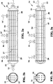
- the heat exchanger 14 is tubular in the illustrated solution.
- the heat exchanger 14 comprises a shell 24 and a tube bundle inserted in the shell 24.
- Flow diverting partitions 27 are also provided inside the shell 24.
- the tubes in the tube bundle are piggable.
- the working fluid is located tube-side, whereas the refrigerant is located shell-side.
- the shell 24 is divided into a first chamber 29 for containing the refrigerant of first refrigeration circuit 16 and a second chamber 30 for containing the refrigerant of the second refrigeration circuit 16'.
- the exchanger 14 is configured for pure counter-current exchange, and therefore the inlet ends of all the tubes for the working fluid communicate with a manifold 31 located at one end of the shell 24 and the outlet ends communicate with a manifold 32 located at the opposite end of the shell 24.
- FIG. 3a and 3b A different embodiment of the invention is illustrated in Figures 3a and 3b .
- the working fluid is located tube-side and the refrigerant is located shell-side.
- the shell 24 is divided, into a first chamber 29 for containing the refrigerant of first refrigeration circuit 16 and a second chamber 30 for containing the refrigerant of the second refrigeration circuit 16'.
- the exchanger 14 is configured for not pure counter-current exchange, and therefore all the tubes 45 for the working fluid are U-shaped so as to position both the inlet end and the outlet end at a manifold 34 located at one end of the shell 24.
- FIG. 4a and 4b A different embodiment of the invention is illustrated in Figures 4a and 4b .
- the working fluid is located shell-side, whereas the refrigerant is located tube-side.
- the tube bundle is divided into a first sub-bundle of tubes 35 for circulation of the refrigerant in the first refrigeration circuit 16 and a second sub-bundle of tubes 36 for circulation of the refrigerant in the second refrigeration circuit 16'.
- the exchanger 14 is configured for pure counter-current exchange, and therefore the inlet ends of all the tubes 35 and 36, respectively, for the refrigerant of the first refrigeration circuit 16 and the second refrigeration circuit 16', respectively, communicate with a respective inlet manifold 37, 37' located at one end of the shell 24 and the outlet ends communicate with a respective outlet manifold 38, 38' located at the opposite end of the shell 24.
- FIG. 5a and 5b A different embodiment of the invention is illustrated in Figures 5a and 5b .
- the working fluid is located shell-side and the refrigerant is located tube-side.
- the tube bundle is again divided into a first sub-bundle of tubes 55 for circulation of the refrigerant in the first refrigeration circuit 16 and a second sub-bundle of tubes 56 for circulation of the refrigerant in the second refrigeration circuit 16'.
- the exchanger 14 is configured for not pure counter-current exchange, and therefore all the tubes 55, 56 are U-shaped so that all the manifolds, that is, the inlet manifolds 57, 57' and the outlet manifolds 58, 58' are positioned at one end of the shell 24.
- the system comprises one-way valves 23 for properly directing the working fluid in the various operating modes.
- the refrigeration system operates as follows.
- valve 8 In the "free-cooling" operating mode, the valve 8 is in a state in which the port 8b is closed and the ports 8a and 8c are open, the circulation pump 15 is off and the compressor for the refrigeration circuits is off.
- valve 8 In the “combined" operating mode as well, the valve 8 is in the state in which the port 8b is closed and the ports 8a and 8c are open, the circulation pump 15 is off and the compressor for the refrigeration circuits is off.
- Cooling of the working fluid is carried out in a cascaded process by the forced ventilation means 9, 9' for ventilating the air cooling batteries 6, 6' and by the evaporator 7.
- valve 8 switches into a state in which the port 8b is open, the port 8a is open and the port 8c is closed, the circulation pump 15 is on, and the compressor for the refrigeration circuits is on.
- Primary circulation of working fluid is established in the section 3 of the working fluid circuit comprising the evaporator 7, and secondary circulation of working fluid is established in the sections 33, 43, 13 of the working fluid circuit comprising the air cooling batteries 6, 6' and the sub-cooling exchanger 14.
- the temperature of the working fluid circulating in the exchanger 14 is always lower than that of the condensed refrigerants and therefore the working fluid removes heat from the latter.
- the refrigeration performance of the system is enhanced by virtue of the higher enthalpy jump produced by the evaporator 7.
- the efficiency of the evaporator 7 improves, which leads to a higher evaporation temperature, with the power exchanged being equal, owing to the lower concentration with which it is supplied.
- this cooling exchanger is a tubular-type exchanger
- the tubes are piggable, thus making it possible to carry out maintenance and cleaning procedures needed to ensure efficient heat exchange over time and therefore, ultimately, ensuring high efficiency levels.
- this solution offers lower load losses on working fluid-side, resulting in savings in the pumping power to be used.
- the refrigeration circuits can have the same exchange surface or even different exchange surfaces.
Landscapes
- Engineering & Computer Science (AREA)
- Physics & Mathematics (AREA)
- Thermal Sciences (AREA)
- Mechanical Engineering (AREA)
- General Engineering & Computer Science (AREA)
- Chemical & Material Sciences (AREA)
- Combustion & Propulsion (AREA)
- Devices That Are Associated With Refrigeration Equipment (AREA)
Claims (10)
- Kälteanlage mit freier Kühlung, umfassend:einen Arbeitsfluidkreislauf umfassend ein zu kühlendes Arbeitsfluid (3, 13, 33, 43), einen ersten (16) und mindestens einen zweiten (16') Kältekreislauf mit einem Kältekreislauf, die jeweils ein Kältemittel umfassen, und wobei eine Unterkühleinheit (14) Wärmeaustauschmittel aufweist,die einen Wärmetauscher (14) umfassen, der mit dem Arbeitsfluidkreislauf verbunden ist und mit dem ersten und mindestens dem zweiten Kältekreislauf (16, 16') verbunden ist und von diesen gemeinsam genutzt wird, wo ein Wärmeaustausch zwischen dem Arbeitsfluid und den kondensierten Kältemitteln stattfindet, wobei das Arbeitsfluid die in den Kältekreisläufen zirkulierenden Kältemittel unterkühlt, wobei das Kälteanlage ferner eine erste (6) und mindestens eine zweite (6') Luftkühlungsbatterie umfasst, die beide auf parallel in den Arbeitsfluidkreislauf gesetzten Abschnitten eingesetzt sind, wobei die erste und mindestens die zweite Luftkühlungsbatterie (6, 6') jeweils von einem jeweiligen Verflüssiger (10, 10') flankiert ist, der in dem ersten und mindestens dem zweiten Kältekreislauf (16, 16') bereitgestellt ist, wobei erste Zwangsbelüftungsmittel (9), die der ersten Luftkühlungsbatterie (6) einen Luftstrom zuführen,um das Arbeitsfluid zu kühlen, bereitgestellt sind und von der ersten Luftkühlungsbatterie (6) und dem Verflüssiger (10) des ersten Kältekreislaufs (16') gemeinsam genutzt werden, wobei mindestens zweite Zwangsbelüftungsmittel (9), die der zweiten Luftkühlungsbatterie (6) einen Luftstrom zuführen,um das Arbeitsfluid zu kühlen, bereitgestellt sind und von der zweiten Luftkühlungsbatterie (6) und dem Verflüssiger (10) des mindestens zweiten Kältekreislaufs (16') gemeinsam genutzt werden, und wobei das Kälteanlage ferner einen gemeinsamen Verdampfer (7) umfasst, der mit dem ersten und mindestens dem zweiten Kältekreislauf (16, 16') und mit dem Arbeitsfluidkreislauf verbunden ist, wo die Kühlung des Arbeitsfluids stattfindet.
- Kälteanlage mit freier Kühlung nach Anspruch 1, wobei der Wärmetauscher (14) mehrere kältemittelseitige Kreisläufe und nur einen arbeitsfluidseitigen Kreislauf aufweist.
- Kälteanlage mit freier Kühlung nach einem der vorhergehenden Ansprüche, wobei der Wärmetauscher (14) rohrförmig ist.
- Kälteanlage mit freier Kühlung nach dem vorhergehenden Anspruch, wobei der Wärmetauscher (14) eine Schale (24) und ein in der Schale (24) eingesetztes Rohrbündel (25, 45, 35, 36, 55, 56) aufweist.
- Kälteanlage mit freier Kühlung nach dem vorhergehenden Anspruch, wobei den Strom umlenkende Trennwände (27) im Inneren der Schale (24) bereitgestellt sind.
- Kälteanlage mit freier Kühlung nach Anspruch 4 oder 5, wobei die Rohre (25, 45, 35, 36, 55, 56) in dem Rohrbündel molchbar sind.
- Kälteanlage mit freier Kühlung nach einem der Ansprüche 4 bis 6, wobei das Arbeitsfluid rohrseitig angeordnet ist und das Kältemittel schalenseitig angeordnet ist, wobei die Schale (24) jeweils in eine erste und mindestens eine zweite Kammer (29, 30) zum Enthalten des Kältemittels des ersten und mindestens eines zweiten Kältekreislaufs (16, 16') geteilt ist.
- Kälteanlage mit freier Kühlung nach einem der Ansprüche 3 bis 7, wobei das Arbeitsfluid schalenseitig angeordnet ist und das Kältemittel rohrseitig angeordnet ist.
- Kälteanlage mit freier Kühlung nach einem der Ansprüche 3 bis 7, wobei das Arbeitsfluid im Wärmetauscher (14) im Gegenstrom zum Kältemittel fließt.
- Kälteanlage mit freier Kühlung nach einem der Ansprüche 1 und 2, wobei es sich bei dem Wärmetauscher (14) um einen Plattenwärmetauscher handelt.
Applications Claiming Priority (1)
| Application Number | Priority Date | Filing Date | Title |
|---|---|---|---|
| ITUA2016A002491A ITUA20162491A1 (it) | 2016-04-11 | 2016-04-11 | Impianto di refrigerazione del tipo “free cooling” con sotto raffreddatore del fluido frigorigeno |
Publications (2)
| Publication Number | Publication Date |
|---|---|
| EP3232138A1 EP3232138A1 (de) | 2017-10-18 |
| EP3232138B1 true EP3232138B1 (de) | 2021-09-08 |
Family
ID=56413792
Family Applications (1)
| Application Number | Title | Priority Date | Filing Date |
|---|---|---|---|
| EP17165891.7A Active EP3232138B1 (de) | 2016-04-11 | 2017-04-11 | Kälteanlage mit freier kühlung mit kältemittelunterkühler |
Country Status (2)
| Country | Link |
|---|---|
| EP (1) | EP3232138B1 (de) |
| IT (1) | ITUA20162491A1 (de) |
Families Citing this family (2)
| Publication number | Priority date | Publication date | Assignee | Title |
|---|---|---|---|---|
| EP3760951B1 (de) | 2019-07-05 | 2022-04-27 | Carrier Corporation | Luftbehandlungseinheit und verfahren zur steuerung solch einer luftbehandlungseinheit |
| NL2024869B1 (en) * | 2020-02-10 | 2021-10-05 | Heatmatrix Group B V | Gas-gas shell and tube heat exchanger |
Family Cites Families (9)
| Publication number | Priority date | Publication date | Assignee | Title |
|---|---|---|---|---|
| US6293106B1 (en) * | 2000-05-18 | 2001-09-25 | Praxair Technology, Inc. | Magnetic refrigeration system with multicomponent refrigerant fluid forecooling |
| US6536231B2 (en) * | 2001-05-31 | 2003-03-25 | Carrier Corporation | Tube and shell heat exchanger for multiple circuit refrigerant system |
| CN102549361B (zh) * | 2009-08-14 | 2014-12-24 | 江森自控科技公司 | 自然冷却制冷系统 |
| US20110132005A1 (en) * | 2009-12-09 | 2011-06-09 | Thomas Edward Kilburn | Refrigeration Process and Apparatus with Subcooled Refrigerant |
| BE1019332A5 (nl) * | 2010-05-11 | 2012-06-05 | Atlas Copco Airpower Nv | Warmtewisselaar. |
| US8505324B2 (en) * | 2010-10-25 | 2013-08-13 | Toyota Motor Engineering & Manufacturing North America, Inc. | Independent free cooling system |
| JP5392298B2 (ja) * | 2011-05-27 | 2014-01-22 | 株式会社デンソー | バッテリの冷却装置 |
| ITMI20111061A1 (it) * | 2011-06-13 | 2012-12-14 | Climaveneta S P A | Impianto per la refrigerazione di un liquido e metodo di controllo di tale impianto |
| US9581364B2 (en) * | 2013-03-15 | 2017-02-28 | Johnson Controls Technology Company | Refrigeration system with free-cooling |
-
2016
- 2016-04-11 IT ITUA2016A002491A patent/ITUA20162491A1/it unknown
-
2017
- 2017-04-11 EP EP17165891.7A patent/EP3232138B1/de active Active
Also Published As
| Publication number | Publication date |
|---|---|
| EP3232138A1 (de) | 2017-10-18 |
| ITUA20162491A1 (it) | 2017-10-11 |
Similar Documents
| Publication | Publication Date | Title |
|---|---|---|
| US7640763B2 (en) | Hot water supply system | |
| KR101638675B1 (ko) | 복합 이원 냉동 사이클 장치 | |
| CN104048434B (zh) | 带自由冷却的制冷系统 | |
| CN107860151B (zh) | 热泵系统及具有其的空调器 | |
| CN107421161B (zh) | 热泵式饮水系统及其控制方法、热泵式饮水装置 | |
| US11578898B2 (en) | Air conditioning apparatus | |
| US11781788B2 (en) | Cascade air conditioner system | |
| EP2165135B1 (de) | Kühlsystem | |
| KR101640127B1 (ko) | 쉘 엔 튜브식 열교환기와 냉각수탱크 일체형 응축기 및 증발기로 구성된 냉동사이클 | |
| EP3232138A1 (de) | Kälteanlage mit freier kühlung mit kältemittelunterkühler | |
| CN106196376B (zh) | 具有一体式多蒸发温度结构的单元式空气调节机 | |
| KR102413937B1 (ko) | 냉장고 | |
| CN108759139B (zh) | 具有中温蒸发器的一次节流中间不完全冷却的制冷系统 | |
| CN108692489B (zh) | 热交换器用连接装置 | |
| KR20100005736U (ko) | 히트펌프 시스템 | |
| CN104697232A (zh) | 热泵系统 | |
| CN112303948A (zh) | 多级换热系统 | |
| CN219015052U (zh) | 换热装置及空调 | |
| EP2642221A2 (de) | Kälteanlage | |
| CN111076439B (zh) | 补气结构、离心式冷水机组及空调器 | |
| JP2006038306A (ja) | 冷凍装置 | |
| CN210921849U (zh) | 冷水机组以及一级泵可变流量系统 | |
| CN211041486U (zh) | 壳管式冷凝器及空调系统 | |
| JP2016125774A (ja) | 冷凍サイクル装置 | |
| KR102019678B1 (ko) | 2단 열교환기로 구성되는 공기열 히트펌프시스템 |
Legal Events
| Date | Code | Title | Description |
|---|---|---|---|
| PUAI | Public reference made under article 153(3) epc to a published international application that has entered the european phase |
Free format text: ORIGINAL CODE: 0009012 |
|
| STAA | Information on the status of an ep patent application or granted ep patent |
Free format text: STATUS: THE APPLICATION HAS BEEN PUBLISHED |
|
| AK | Designated contracting states |
Kind code of ref document: A1 Designated state(s): AL AT BE BG CH CY CZ DE DK EE ES FI FR GB GR HR HU IE IS IT LI LT LU LV MC MK MT NL NO PL PT RO RS SE SI SK SM TR |
|
| AX | Request for extension of the european patent |
Extension state: BA ME |
|
| STAA | Information on the status of an ep patent application or granted ep patent |
Free format text: STATUS: REQUEST FOR EXAMINATION WAS MADE |
|
| 17P | Request for examination filed |
Effective date: 20180208 |
|
| RBV | Designated contracting states (corrected) |
Designated state(s): AL AT BE BG CH CY CZ DE DK EE ES FI FR GB GR HR HU IE IS IT LI LT LU LV MC MK MT NL NO PL PT RO RS SE SI SK SM TR |
|
| RAP1 | Party data changed (applicant data changed or rights of an application transferred) |
Owner name: MITSUBISHI ELECTRIC HYDRONICS & IT COOLING SYSTEMS |
|
| GRAP | Despatch of communication of intention to grant a patent |
Free format text: ORIGINAL CODE: EPIDOSNIGR1 |
|
| STAA | Information on the status of an ep patent application or granted ep patent |
Free format text: STATUS: GRANT OF PATENT IS INTENDED |
|
| INTG | Intention to grant announced |
Effective date: 20210611 |
|
| GRAS | Grant fee paid |
Free format text: ORIGINAL CODE: EPIDOSNIGR3 |
|
| GRAA | (expected) grant |
Free format text: ORIGINAL CODE: 0009210 |
|
| STAA | Information on the status of an ep patent application or granted ep patent |
Free format text: STATUS: THE PATENT HAS BEEN GRANTED |
|
| AK | Designated contracting states |
Kind code of ref document: B1 Designated state(s): AL AT BE BG CH CY CZ DE DK EE ES FI FR GB GR HR HU IE IS IT LI LT LU LV MC MK MT NL NO PL PT RO RS SE SI SK SM TR |
|
| REG | Reference to a national code |
Ref country code: GB Ref legal event code: FG4D |
|
| REG | Reference to a national code |
Ref country code: AT Ref legal event code: REF Ref document number: 1428925 Country of ref document: AT Kind code of ref document: T Effective date: 20210915 Ref country code: CH Ref legal event code: EP |
|
| REG | Reference to a national code |
Ref country code: IE Ref legal event code: FG4D |
|
| REG | Reference to a national code |
Ref country code: DE Ref legal event code: R096 Ref document number: 602017045541 Country of ref document: DE |
|
| REG | Reference to a national code |
Ref country code: LT Ref legal event code: MG9D |
|
| REG | Reference to a national code |
Ref country code: NL Ref legal event code: MP Effective date: 20210908 |
|
| PG25 | Lapsed in a contracting state [announced via postgrant information from national office to epo] |
Ref country code: SE Free format text: LAPSE BECAUSE OF FAILURE TO SUBMIT A TRANSLATION OF THE DESCRIPTION OR TO PAY THE FEE WITHIN THE PRESCRIBED TIME-LIMIT Effective date: 20210908 Ref country code: RS Free format text: LAPSE BECAUSE OF FAILURE TO SUBMIT A TRANSLATION OF THE DESCRIPTION OR TO PAY THE FEE WITHIN THE PRESCRIBED TIME-LIMIT Effective date: 20210908 Ref country code: NO Free format text: LAPSE BECAUSE OF FAILURE TO SUBMIT A TRANSLATION OF THE DESCRIPTION OR TO PAY THE FEE WITHIN THE PRESCRIBED TIME-LIMIT Effective date: 20211208 Ref country code: ES Free format text: LAPSE BECAUSE OF FAILURE TO SUBMIT A TRANSLATION OF THE DESCRIPTION OR TO PAY THE FEE WITHIN THE PRESCRIBED TIME-LIMIT Effective date: 20210908 Ref country code: FI Free format text: LAPSE BECAUSE OF FAILURE TO SUBMIT A TRANSLATION OF THE DESCRIPTION OR TO PAY THE FEE WITHIN THE PRESCRIBED TIME-LIMIT Effective date: 20210908 Ref country code: HR Free format text: LAPSE BECAUSE OF FAILURE TO SUBMIT A TRANSLATION OF THE DESCRIPTION OR TO PAY THE FEE WITHIN THE PRESCRIBED TIME-LIMIT Effective date: 20210908 Ref country code: BG Free format text: LAPSE BECAUSE OF FAILURE TO SUBMIT A TRANSLATION OF THE DESCRIPTION OR TO PAY THE FEE WITHIN THE PRESCRIBED TIME-LIMIT Effective date: 20211208 Ref country code: LT Free format text: LAPSE BECAUSE OF FAILURE TO SUBMIT A TRANSLATION OF THE DESCRIPTION OR TO PAY THE FEE WITHIN THE PRESCRIBED TIME-LIMIT Effective date: 20210908 |
|
| REG | Reference to a national code |
Ref country code: AT Ref legal event code: MK05 Ref document number: 1428925 Country of ref document: AT Kind code of ref document: T Effective date: 20210908 |
|
| PG25 | Lapsed in a contracting state [announced via postgrant information from national office to epo] |
Ref country code: LV Free format text: LAPSE BECAUSE OF FAILURE TO SUBMIT A TRANSLATION OF THE DESCRIPTION OR TO PAY THE FEE WITHIN THE PRESCRIBED TIME-LIMIT Effective date: 20210908 Ref country code: GR Free format text: LAPSE BECAUSE OF FAILURE TO SUBMIT A TRANSLATION OF THE DESCRIPTION OR TO PAY THE FEE WITHIN THE PRESCRIBED TIME-LIMIT Effective date: 20211209 |
|
| PG25 | Lapsed in a contracting state [announced via postgrant information from national office to epo] |
Ref country code: AT Free format text: LAPSE BECAUSE OF FAILURE TO SUBMIT A TRANSLATION OF THE DESCRIPTION OR TO PAY THE FEE WITHIN THE PRESCRIBED TIME-LIMIT Effective date: 20210908 |
|
| PG25 | Lapsed in a contracting state [announced via postgrant information from national office to epo] |
Ref country code: IS Free format text: LAPSE BECAUSE OF FAILURE TO SUBMIT A TRANSLATION OF THE DESCRIPTION OR TO PAY THE FEE WITHIN THE PRESCRIBED TIME-LIMIT Effective date: 20220108 Ref country code: SM Free format text: LAPSE BECAUSE OF FAILURE TO SUBMIT A TRANSLATION OF THE DESCRIPTION OR TO PAY THE FEE WITHIN THE PRESCRIBED TIME-LIMIT Effective date: 20210908 Ref country code: SK Free format text: LAPSE BECAUSE OF FAILURE TO SUBMIT A TRANSLATION OF THE DESCRIPTION OR TO PAY THE FEE WITHIN THE PRESCRIBED TIME-LIMIT Effective date: 20210908 Ref country code: RO Free format text: LAPSE BECAUSE OF FAILURE TO SUBMIT A TRANSLATION OF THE DESCRIPTION OR TO PAY THE FEE WITHIN THE PRESCRIBED TIME-LIMIT Effective date: 20210908 Ref country code: PT Free format text: LAPSE BECAUSE OF FAILURE TO SUBMIT A TRANSLATION OF THE DESCRIPTION OR TO PAY THE FEE WITHIN THE PRESCRIBED TIME-LIMIT Effective date: 20220110 Ref country code: PL Free format text: LAPSE BECAUSE OF FAILURE TO SUBMIT A TRANSLATION OF THE DESCRIPTION OR TO PAY THE FEE WITHIN THE PRESCRIBED TIME-LIMIT Effective date: 20210908 Ref country code: NL Free format text: LAPSE BECAUSE OF FAILURE TO SUBMIT A TRANSLATION OF THE DESCRIPTION OR TO PAY THE FEE WITHIN THE PRESCRIBED TIME-LIMIT Effective date: 20210908 Ref country code: EE Free format text: LAPSE BECAUSE OF FAILURE TO SUBMIT A TRANSLATION OF THE DESCRIPTION OR TO PAY THE FEE WITHIN THE PRESCRIBED TIME-LIMIT Effective date: 20210908 Ref country code: CZ Free format text: LAPSE BECAUSE OF FAILURE TO SUBMIT A TRANSLATION OF THE DESCRIPTION OR TO PAY THE FEE WITHIN THE PRESCRIBED TIME-LIMIT Effective date: 20210908 Ref country code: AL Free format text: LAPSE BECAUSE OF FAILURE TO SUBMIT A TRANSLATION OF THE DESCRIPTION OR TO PAY THE FEE WITHIN THE PRESCRIBED TIME-LIMIT Effective date: 20210908 |
|
| REG | Reference to a national code |
Ref country code: DE Ref legal event code: R097 Ref document number: 602017045541 Country of ref document: DE |
|
| PLBE | No opposition filed within time limit |
Free format text: ORIGINAL CODE: 0009261 |
|
| STAA | Information on the status of an ep patent application or granted ep patent |
Free format text: STATUS: NO OPPOSITION FILED WITHIN TIME LIMIT |
|
| PG25 | Lapsed in a contracting state [announced via postgrant information from national office to epo] |
Ref country code: DK Free format text: LAPSE BECAUSE OF FAILURE TO SUBMIT A TRANSLATION OF THE DESCRIPTION OR TO PAY THE FEE WITHIN THE PRESCRIBED TIME-LIMIT Effective date: 20210908 |
|
| 26N | No opposition filed |
Effective date: 20220609 |
|
| PG25 | Lapsed in a contracting state [announced via postgrant information from national office to epo] |
Ref country code: SI Free format text: LAPSE BECAUSE OF FAILURE TO SUBMIT A TRANSLATION OF THE DESCRIPTION OR TO PAY THE FEE WITHIN THE PRESCRIBED TIME-LIMIT Effective date: 20210908 |
|
| REG | Reference to a national code |
Ref country code: CH Ref legal event code: PL |
|
| REG | Reference to a national code |
Ref country code: BE Ref legal event code: MM Effective date: 20220430 |
|
| PG25 | Lapsed in a contracting state [announced via postgrant information from national office to epo] |
Ref country code: MC Free format text: LAPSE BECAUSE OF FAILURE TO SUBMIT A TRANSLATION OF THE DESCRIPTION OR TO PAY THE FEE WITHIN THE PRESCRIBED TIME-LIMIT Effective date: 20210908 Ref country code: LU Free format text: LAPSE BECAUSE OF NON-PAYMENT OF DUE FEES Effective date: 20220411 Ref country code: LI Free format text: LAPSE BECAUSE OF NON-PAYMENT OF DUE FEES Effective date: 20220430 Ref country code: IT Free format text: LAPSE BECAUSE OF FAILURE TO SUBMIT A TRANSLATION OF THE DESCRIPTION OR TO PAY THE FEE WITHIN THE PRESCRIBED TIME-LIMIT Effective date: 20210908 Ref country code: CH Free format text: LAPSE BECAUSE OF NON-PAYMENT OF DUE FEES Effective date: 20220430 |
|
| PG25 | Lapsed in a contracting state [announced via postgrant information from national office to epo] |
Ref country code: BE Free format text: LAPSE BECAUSE OF NON-PAYMENT OF DUE FEES Effective date: 20220430 |
|
| PG25 | Lapsed in a contracting state [announced via postgrant information from national office to epo] |
Ref country code: IE Free format text: LAPSE BECAUSE OF NON-PAYMENT OF DUE FEES Effective date: 20220411 |
|
| P01 | Opt-out of the competence of the unified patent court (upc) registered |
Effective date: 20230524 |
|
| PG25 | Lapsed in a contracting state [announced via postgrant information from national office to epo] |
Ref country code: HU Free format text: LAPSE BECAUSE OF FAILURE TO SUBMIT A TRANSLATION OF THE DESCRIPTION OR TO PAY THE FEE WITHIN THE PRESCRIBED TIME-LIMIT; INVALID AB INITIO Effective date: 20170411 |
|
| PG25 | Lapsed in a contracting state [announced via postgrant information from national office to epo] |
Ref country code: MK Free format text: LAPSE BECAUSE OF FAILURE TO SUBMIT A TRANSLATION OF THE DESCRIPTION OR TO PAY THE FEE WITHIN THE PRESCRIBED TIME-LIMIT Effective date: 20210908 Ref country code: CY Free format text: LAPSE BECAUSE OF FAILURE TO SUBMIT A TRANSLATION OF THE DESCRIPTION OR TO PAY THE FEE WITHIN THE PRESCRIBED TIME-LIMIT Effective date: 20210908 |
|
| PG25 | Lapsed in a contracting state [announced via postgrant information from national office to epo] |
Ref country code: TR Free format text: LAPSE BECAUSE OF FAILURE TO SUBMIT A TRANSLATION OF THE DESCRIPTION OR TO PAY THE FEE WITHIN THE PRESCRIBED TIME-LIMIT Effective date: 20210908 |
|
| PG25 | Lapsed in a contracting state [announced via postgrant information from national office to epo] |
Ref country code: MT Free format text: LAPSE BECAUSE OF FAILURE TO SUBMIT A TRANSLATION OF THE DESCRIPTION OR TO PAY THE FEE WITHIN THE PRESCRIBED TIME-LIMIT Effective date: 20210908 |
|
| PGFP | Annual fee paid to national office [announced via postgrant information from national office to epo] |
Ref country code: DE Payment date: 20250428 Year of fee payment: 9 |
|
| PGFP | Annual fee paid to national office [announced via postgrant information from national office to epo] |
Ref country code: GB Payment date: 20250401 Year of fee payment: 9 |
|
| PGFP | Annual fee paid to national office [announced via postgrant information from national office to epo] |
Ref country code: FR Payment date: 20250424 Year of fee payment: 9 |