EP3231981B1 - Érecteur pour une fusée souterraine destiné au positionnement de la fusée souterraine dans une fouille de départ, système de forage comportant une fusée souterraine et érecteur de positionnement de la fusée souterraine dans une fouille de départ et procédé de positionnement d'une fusée souterraine dans une fouille de départ - Google Patents
Érecteur pour une fusée souterraine destiné au positionnement de la fusée souterraine dans une fouille de départ, système de forage comportant une fusée souterraine et érecteur de positionnement de la fusée souterraine dans une fouille de départ et procédé de positionnement d'une fusée souterraine dans une fouille de départ Download PDFInfo
- Publication number
- EP3231981B1 EP3231981B1 EP17000572.2A EP17000572A EP3231981B1 EP 3231981 B1 EP3231981 B1 EP 3231981B1 EP 17000572 A EP17000572 A EP 17000572A EP 3231981 B1 EP3231981 B1 EP 3231981B1
- Authority
- EP
- European Patent Office
- Prior art keywords
- rocket
- carriage
- drilling
- clamp
- excavation
- Prior art date
- Legal status (The legal status is an assumption and is not a legal conclusion. Google has not performed a legal analysis and makes no representation as to the accuracy of the status listed.)
- Active
Links
Images


Classifications
-
- E—FIXED CONSTRUCTIONS
- E21—EARTH OR ROCK DRILLING; MINING
- E21B—EARTH OR ROCK DRILLING; OBTAINING OIL, GAS, WATER, SOLUBLE OR MELTABLE MATERIALS OR A SLURRY OF MINERALS FROM WELLS
- E21B12/00—Accessories for drilling tools
-
- E—FIXED CONSTRUCTIONS
- E21—EARTH OR ROCK DRILLING; MINING
- E21B—EARTH OR ROCK DRILLING; OBTAINING OIL, GAS, WATER, SOLUBLE OR MELTABLE MATERIALS OR A SLURRY OF MINERALS FROM WELLS
- E21B15/00—Supports for the drilling machine, e.g. derricks or masts
- E21B15/04—Supports for the drilling machine, e.g. derricks or masts specially adapted for directional drilling, e.g. slant hole rigs
-
- E—FIXED CONSTRUCTIONS
- E21—EARTH OR ROCK DRILLING; MINING
- E21B—EARTH OR ROCK DRILLING; OBTAINING OIL, GAS, WATER, SOLUBLE OR MELTABLE MATERIALS OR A SLURRY OF MINERALS FROM WELLS
- E21B4/00—Drives for drilling, used in the borehole
- E21B4/06—Down-hole impacting means, e.g. hammers
- E21B4/14—Fluid operated hammers
-
- E—FIXED CONSTRUCTIONS
- E21—EARTH OR ROCK DRILLING; MINING
- E21B—EARTH OR ROCK DRILLING; OBTAINING OIL, GAS, WATER, SOLUBLE OR MELTABLE MATERIALS OR A SLURRY OF MINERALS FROM WELLS
- E21B7/00—Special methods or apparatus for drilling
- E21B7/04—Directional drilling
- E21B7/046—Directional drilling horizontal drilling
-
- E—FIXED CONSTRUCTIONS
- E21—EARTH OR ROCK DRILLING; MINING
- E21B—EARTH OR ROCK DRILLING; OBTAINING OIL, GAS, WATER, SOLUBLE OR MELTABLE MATERIALS OR A SLURRY OF MINERALS FROM WELLS
- E21B7/00—Special methods or apparatus for drilling
- E21B7/26—Drilling without earth removal, e.g. with self-propelled burrowing devices
Definitions
- the invention relates to a carriage for a soil rocket for positioning the soil rocket in a starting pit, a drilling system with a soil rocket and a carriage for positioning the soil rocket in a starting pit and a method for positioning a soil rocket in a starting pit.
- EN 10 2011 101 442 A1 discloses a carriage for a soil rocket for positioning the same in a starting pit.
- a holder for the carriage is described, which is adjustable in height and inclination.
- the soil rocket arranged in the holder can be moved into a starting pit at an adjustable angle using a drive on a swivel joint.
- the soil rocket can be placed on the holder on the surface of the starting pit.
- NL 8 501 041 A discloses a device for introducing a drill pipe, a cable, a line or the like into the ground.
- Two clamping and support devices are provided, which have optionally opening and closing clamping jaws.
- the clamping and support devices are located on a carriage and can be moved together in order to pull the drill pipe out of the ground or to insert it into the ground.
- DE 101 43 909 A1 discloses a device and a method for aligning an earth drilling device, wherein a holder for an earth rocket is described. Using two operating elements in the form of threaded rods connected to the holder, the holder can be aligned so that the earth rocket can enter the ground at a desired angle.
- the core idea of the invention is to provide two mounts that can accommodate the earth-moving rocket and whose height can be moved independently of one another for handling the earth-moving rocket.
- the different movement of the mounts allows an angle of the earth-moving rocket, which it encloses with a fixed reference line, to be set without having to provide a special drive for the inclination, for example on a rotary joint.
- the control of the mounts can thus be simplified.
- the control of the mounts can be reduced to a translational movement of the mounts.
- Control of a controllable rotary joint is not necessary, and in particular a carriage according to the invention cannot have a drive for rotation or rotation of a rotary joint.
- Identical components can be used for guides, drives and/or sensors, whereby a rotary drive can be omitted.
- Linear drives can serve as guides. With two mounts, positioning can be carried out more stably.
- the invention provides a carriage for a soil rocket for positioning the soil rocket in a starting pit, according to claim 1.
- the carriage has two mounts.
- One mount includes a clamp for the earth-moving rocket.
- the clamps and mounts can be operated independently of each other.
- the mounts can be moved in height independently of each other.
- soil rocket covers a device for creating a borehole in the ground using a soil displacement process.
- soil rocket is synonymous with an earth displacement hammer, which can also be called a soil penetration rocket.
- an essentially circular displacement body is driven in one direction by means of a percussion piston located in a housing of the displacement body.
- the propulsion is usually achieved by compressed air, i.e. pneumatically, whereby the percussion piston hits the housing of the displacement body directly or indirectly due to the compressed air, thereby generating the energy required to displace the soil.
- the propulsion can also be achieved hydraulically.
- the term "positioning” includes moving the earth-piercing rocket, in particular to move the earth-piercing rocket from a position above the ground to a position below or within the ground in the starting excavation pit.
- the positioning can include positioning the earth-piercing rocket before and at the start of the drilling of the earth.
- starting pit includes any type of space below the earth's surface, including excavated or existing pits.
- a starting pit can have a substantially circular cross-section.
- the diameter of a starting pit can be in particular in the range from approximately 400 mm to approximately 900 mm, in particular in the range from approximately 500 mm to approximately 800 mm.
- a common size for a starting pit is a diameter of approximately 600 mm, for example.
- starting pit includes in particular a starting pit of the so-called "keyhole” technique in horizontal drilling.
- the carriage in the sense of the invention includes all types of frames or supports that are suitable for receiving and aligning a soil rocket.
- the carriage can have a frame whose outer contour is adapted to the outer dimensions of the starting pit.
- the carriage has a frame that can be arranged above the starting pit and extends into the starting pit.
- the carriage is designed to rest on the surface of the earth and that a section extends into the starting pit without the carriage standing on the floor of the starting pit.
- the frame can rest on the ground and hang in the starting pit.
- the carriage can have a support that rests on a base arranged on the ground around the starting pit, which is designed, for example, in the form of a receiving flange.
- the frame can have one or more openings through which the soil rocket can be inserted into the corresponding receptacles. This makes it possible to achieve a stable structure while at the same time being easy to handle.
- the arrangement of the carriage can be such that after the starting pit has been dug, a base designed as a receiving flange is inserted into the ground around or into the starting pit.
- the base can rest on the ground and be supported against the ground on the circumference at the edge of the starting pit.
- the base which is designed in particular as a receiving flange, can be braced against the ground.
- the carriage can have a support designed as a counter flange, which is designed in particular on the circumference around the frame of the carriage or on the frame.
- the support can be moved relative to the base, in particular to set the aiming direction of the soil rocket to be inserted into the carriage. Once the aiming direction has been determined, the support can be braced relative to the base.
- the carriage can be aligned in height and, for example, adjusted vertically using four grooves/slot nuts distributed around the circumference and then fixed.
- the term "receptacle” comprises a technical element on which the earth-moving rocket can rest, wherein the earth-moving rocket can be at least partially surrounded by the receptacle along its circumference.
- clamp in the sense of the invention includes a component which is designed for a detachable connection of the earth auger to the holder, whereby in particular a force connection between the earth auger and the clamp can be achieved.
- the earth auger can be fixed to the holder by means of the clamp. It is particularly possible for surfaces aligned with one another to be moved towards one another so that the earth auger can be clamped at one section on the circumference. Sections of the clamp along the circumference of the earth auger can be brought into contact with the earth auger.
- At least one mount for the earth auger is freely pivotably mounted so that the mount can be freely pivoted.
- at least one of the mounts can be fixed in terms of the rotation of the mount by fixing the earth auger in the other of the two mounts.
- the freely pivotable mounting of a mount enables a reduction of one motor or drive for setting a corresponding angle.
- the receptacles are guided in guides that are aligned essentially vertically. This ensures that the receptacles can move along a predetermined path.
- a connecting line can be determined between the receptacles, which can essentially correspond to the longitudinal direction or central axis of the earth-moving rocket received in the receptacles.
- the position of the earth-moving rocket can thus be determined by the position of the receptacle in the guide.
- the guides can have a deviation from the purely vertical direction, whereby a purely vertical alignment of the guides with an essentially parallel arrangement of the guides to one another is preferred. Since the earth-moving rocket extends essentially along a straight line, the position of the earth-moving rocket can be determined if the position of the receptacles in the guides is known.
- the clamp surrounds the earth auger at least partially along a circumference, wherein the arrangement of the clamp relative to the travel path of the receptacles can be selected such that effective clamping is achieved.
- the clamp can clamp the earth auger laterally and/or from above and below along the circumference.
- a clamp comprises a pressure chamber with a flexible wall, which can come into contact with the earth auger with the wall. This makes it possible to achieve an effective clamp, which is also easy to manufacture and can adapt to the outer contour of an earth auger. It is possible, for example, that a diameter of the soil hammer can be freely selected and yet a clamping of the soil hammer can be achieved over a certain range of the diameter of the soil hammer.
- the clamp can comprise a pressure chamber which has a flexible wall which can be brought into contact with the earth auger.
- the earth auger can be enclosed at least in sections by the flexible wall, in particular at least partially in the circumferential direction.
- the pressure chamber can be filled using a pressure medium, for example compressed air.
- Such a clamp is simply constructed and, in addition to the elastic casing of the pressure chamber, has a rigid wall which acts as a counter bearing.
- the clamp can be used for several sizes and/or shapes of an earth auger, since the elastic casing can adapt to the outer contour of the element to be clamped.
- the earth auger can have different shapes and/or different diameters.
- the earth auger can be surrounded at least partially or completely by the elastic casing along its circumference.
- the rigid wall can be tubular, so that a clamp which is easy to handle and easy to manufacture can be used.
- tubular here includes an elongated hollow body whose length can be greater than its diameter.
- a tubular wall is suitable for clamping an elongated element such as a soil rocket, whereby the cross-section of the rigid wall can be selected in such a way that excess material can be avoided.
- Steel, a non-ferrous metal, a plastic or a similar material that has a certain strength can be used as the material for the rigid wall.
- the counter bearing is arranged around the shell so that the stretchable shell is located within an element forming the rigid wall.
- the stretchable shell can have a single layer.
- the stretchable shell can consist of a single material.
- An stretchable, single-layer or multi-layer material can be used as the material of the stretchable shell.
- a synthetic rubber preferably nitrile rubber
- An NBR nitrile butadiene rubber
- the stretchable cover has a multi-layer composite, so that the stretchable cover consists of several layers, at least in a partial area. The stretchable cover can be radially pressed with a rigid wall.
- the rigid wall can be designed as an airtight tube in which an expandable sleeve, which can be designed as a flexible, airtight hose, can be arranged.
- the expandable sleeve can be pressed onto the end faces of the tube using radial force elements.
- the expandable sleeve can thus be airtight between the rigid wall and the radial force elements, whereby an airtight pressure chamber can be formed.
- a pressure medium in particular compressed air
- a compressed air opening can be formed in the rigid wall, which can be connected to a pressure medium source.
- the clamp is designed in such a way that more than two positions of the clamp can be set. It is possible, for example, that between the two positions of the clamp, one of the two positions being the release by the clamp and the other of the first two positions corresponding to a complete fixation, so that the earth auger is essentially fixed relative to the receptacle, a third position can be set in which a movement of the earth auger is possible, whereby there is friction of the earth auger for clamping.
- a control system is provided with which at least one receptacle can be moved and/or the clamp can be actuated.
- the control system can be used to actuate the carriage, which can be done in particular by remote control. This means that the carriage can be controlled from above the surface of the earth, even if the carriage has been retracted into the starting pit.
- a control system can be provided with which at least one holder can be moved and/or the clamp can be actuated, with at least one sensor for detecting the movement and/or the actuation of the clamp being arranged on the carriage.
- the sensor can be used to form a control loop in which the actual position of the holder and/or the actual position of the clamp is determined.
- the invention also provides a drilling system with a soil rocket and a carriage for positioning the same, wherein the carriage is designed as described above.
- mounts for the carriage there are two mounts for the carriage, each with a clamp, whereby the clamps and the mounts can be operated independently of each other.
- the mounts can be moved in height independently of each other.
- the invention also provides a method for positioning an earth auger in a starting pit, according to claim 8, wherein two receptacles are used for the earth auger, each of which has a clamp for the earth auger.
- the method comprises the step of operating the receptacles and clamps separately from one another. Furthermore, the receptacles are moved in height independently of one another.
- the earth auger can be clamped in only one holder and/or one holder can be moved. This allows an angle adjustment which can be designed without a drive for a swivel joint.
- a clamping of the earth auger is set in such a way that the earth auger moves when the clamps are applied.
- the clamping can be set up in such a way that a jacket friction acts on the earth auger, which can prevent the earth auger from being moved backwards during operation by reaction forces when moving forwards and forwards when moving backwards.
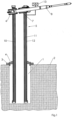
- Fig.1 shows a partially sectioned view of a starting pit 1 that was dug in the ground 2.
- a base 3 is placed on the edge of the starting pit and braced against the edge of the ground 2.
- the base 3 is designed as a support flange and the bracing of the support flange against the ground 2 is carried out by means of a turnbuckle with a ratchet.
- a support 4 of a carriage 5 is placed on the base 3.
- the aiming direction, ie the alignment of the supports 6, 7 of the carriage 5 can then be set by adjusting the Support 4 is rotated relative to base 3 and mounts 6, 7 are rotated accordingly.
- Mount 5 is then attached to base 3 with clamps and fixed in the direction of aim.
- Mount 5 is then adjusted in height.
- Mount 5 is adjusted vertically in support 4 using four grooves/slotted blocks distributed around the circumference and then fixed.
- a soil hammer 8 is inserted into the receptacles 6, 7.
- clamps 9 are provided on the receptacles 6, 7, which are Fig. 5a and 5b shown, in an open position.
- the earth-piercing rocket 8 can thus be pushed above the earth's surface, ie above the soil 2, into the carriage 5 or the receptacles 6, 7.
- the aiming direction is also possible for the aiming direction to be determined after inserting the soil rocket 8 into the receptacles 6, 7.
- the soil rocket 8 can be clamped in the clamps of the receptacles 6, 7.
- a readjustment of the aiming direction is possible at any time, in particular after the soil displacement rocket 8 has at least partially penetrated into the soil 2 to the installation depth.
- the clamp 9 of the front holder 6 is activated and the earth auger 8 is clamped in the holder 6.
- the front of the two holders 6 is lowered via a first guide 10 so that an angle ⁇ 1 is established with respect to an imaginary reference line, which is essentially the horizontal.
- the angle ⁇ 1 can in particular be selected such that the earth auger 8 can be guided through the frame 12, although the length of the earth auger 8 is greater than the inner diameter of the frame 12. This results in the Fig.2 illustrated positioning of the earth rocket 8.
- the mounts 6, 7 are lowered while maintaining the angle ⁇ 1 so that the extension of the central axis of the earth auger 8 results in the penetration point for the earth auger 8 into the ground 2.
- the clamp 9 of the front mount 6 is then relieved and the clamp 9 of the rear mount 7 is loaded so that a jacket friction acts on the earth auger 8. The jacket friction can prevent the earth auger 8 from being moved backwards by reaction forces during operation.
- the earth rocket 8 can be launched.
- the rear mount 7 can be lowered via a second guide 11 over a continuously changing angle of inclination.
- the angle of inclination can change continuously up to an inclination angle for a borehole to be created.
- the front mount 6 can be adjusted so that the tip of the earth-moving rocket 8 describes an approximate circular arc when penetrating the ground 2 and the final angle of inclination can be smaller, larger or equal to zero degrees in relation to the horizontal.
- suction can be carried out using a suction excavator, and the suction can create a scouring hole in the lower area of the starting excavation pit 1.
- the earth-moving rocket 8 can first be set to the inclination of the intended earth drilling and only then started. If a scouring hole has been created at the laying depth, the precise setting of the target direction and/or the setting of the inclination can also take place after the earth-moving rocket 8 has been lowered through the frame 12.
- the earth auger 8 After the earth auger 8 has reached the inclination angle for carrying out the earth drilling, the earth auger 8 can be driven forward to a target excavation pit with the azimuth and inclination angle set.
- the clamps 9 of the holders 6, 7 can be opened as soon as the earth auger 8 has sufficient casing friction with the soil 2 in which the earth auger 8 is now moving. It is possible that a pipe or a line can be pulled in from the starting excavation pit 1 to a target excavation pit using the earth auger 8.
- a control 13 is provided for moving the holders 6, 7 in the guides 10, 11.
- the recovery of the earth rocket 8 after the earth bore has been created can be described in the reverse order of the steps described for positioning the earth rocket 8 before the earth rocket is launched.
- the earth rocket 8 can also take a line or pipe with it that is to be pulled in so that this pipe can be pulled into the earth bore created with or without further widening of the earth bore.
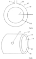
- the Fig. 5a shows a receptacle 6, 7 with a clamp 9 in a partially sectioned view.
- the clamp 9 has a pressure chamber 23 which is formed between a rigid wall 20 and an expandable casing 22.
- a pressure medium in particular compressed air, can be fed into the pressure chamber 23 via an opening 21 in the rigid wall 20.
- the expandable casing 22 can expand in the direction of the center of the rigid wall 20 when the pressure chamber 23 is subjected to pressure medium.
- a soil rocket 8 which is arranged transversely to the clamp 9 in this, ie perpendicular to the plane of the paper, is at least partially clamped around the circumference of the soil rocket.
- Fig. 5b shows the holder 6, 7 with the clamp 9 in an isometric view.
Landscapes
- Engineering & Computer Science (AREA)
- Life Sciences & Earth Sciences (AREA)
- Geology (AREA)
- Mining & Mineral Resources (AREA)
- Physics & Mathematics (AREA)
- Environmental & Geological Engineering (AREA)
- Fluid Mechanics (AREA)
- General Life Sciences & Earth Sciences (AREA)
- Geochemistry & Mineralogy (AREA)
- Mechanical Engineering (AREA)
- Earth Drilling (AREA)
Claims (10)
- Affût (5) pour une fusée souterraine (8) destiné au positionnement de la fusée souterraine dans une fouille de départ (1), l'affût (5) comportant deux logements (6, 7) avec chacun un dispositif de serrage (9), les dispositifs de serrage (9) étant conçus de manière à entourer au moins partiellement la fusée souterraine (8) et les logements (6, 7) étant guidés dans des guides (10, 11) qui sont orientés essentiellement verticalement, l'affût (5) comportant un châssis (12) qui peut être disposé au-dessus de la fouille de départ et qui s'étend jusque dans la fouille de départ, les dispositifs de serrage (9) et les logements (6, 7) pouvant être actionnés indépendamment les uns des autres, les logements (6, 7) étant mobiles en hauteur indépendamment les uns des autres.
- Affût (5) selon la revendication 1, caractérisé en ce que le logement (6, 7) est monté libre en rotation.
- Affût (5) selon la revendication 1 ou 2, caractérisé en ce qu'un dispositif de serrage (9) comprend une chambre de pression (23) comportant une paroi flexible (22).
- Affût (5) selon l'une des revendications 1 à 3, caractérisé en ce que le dispositif de serrage (9) est configuré de telle sorte que plus de deux positions du dispositif de serrage (9) sont réglables.
- Affût (5) selon l'une des revendications 1 à 4, caractérisé en ce qu'il existe une commande (13) permettant de déplacer au moins un logement (6, 7) et/ou d'actionner le dispositif de serrage (9).
- Affût (5) selon l'une des revendications 1 à 5, caractérisé en ce qu'il existe une régulation permettant de déplacer au moins un logement (6, 7) et/ou d'actionner le dispositif de serrage (9), au moins un capteur étant disposé sur l'affût pour détecter le mouvement et/ou l'actionnement du dispositif de serrage (9).
- Système de forage comportant une fusée souterraine (8) et un affût (5) de positionnement de la fusée souterraine (8), l'affût (5) étant configuré selon l'une des revendications 1 à 6.
- Procédé destiné au positionnement d'une fusée souterraine (8) dans une fouille de départ (1), dans lequel deux logements (6, 7), dont chacun comporte un dispositif de serrage (9) pour la fusée souterraine (8) sont utilisés, caractérisé par un actionnement séparé des logements (6, 7) et des dispositifs de serrage (9) l'un de l'autre et un déplacement des logements (6, 7) indépendamment l'un de l'autre en hauteur, les dispositifs de serrage (9) entourant au moins partiellement la fusée souterraine (8), et les logements (6, 7) étant guidés dans des guides (10, 11) qui sont orientés essentiellement verticalement, l'affût (5) comportant un châssis (12) qui est disposé au-dessus de la fouille de départ et qui s'étend jusque dans la fouille de départ.
- Procédé selon la revendication 8, caractérisé par un serrage de la fusée souterraine (8) dans un seul logement (6, 7) et un déplacement dudit un logement (6, 7).
- Procédé selon la revendication 8 ou 9, caractérisé en ce qu'un serrage de la fusée souterraine (8) est réglé de telle sorte que la fusée souterraine (8) se déplace lorsque le serrage est exercé.
Applications Claiming Priority (1)
| Application Number | Priority Date | Filing Date | Title |
|---|---|---|---|
| DE102016003995.7A DE102016003995A1 (de) | 2016-04-07 | 2016-04-07 | Lafette für eine Erdrakete zur Positionierung der Erdrakete in einer Startbaugrube, Bohrsystem mit einer Erdrakete und einer Lafette zur Positionierung der Erdrakete in einer Startbaugrube und Verfahren zum Positionieren einer Erdrakete in einer Startbaugrube |
Publications (2)
| Publication Number | Publication Date |
|---|---|
| EP3231981A1 EP3231981A1 (fr) | 2017-10-18 |
| EP3231981B1 true EP3231981B1 (fr) | 2024-05-08 |
Family
ID=58536700
Family Applications (1)
| Application Number | Title | Priority Date | Filing Date |
|---|---|---|---|
| EP17000572.2A Active EP3231981B1 (fr) | 2016-04-07 | 2017-04-05 | Érecteur pour une fusée souterraine destiné au positionnement de la fusée souterraine dans une fouille de départ, système de forage comportant une fusée souterraine et érecteur de positionnement de la fusée souterraine dans une fouille de départ et procédé de positionnement d'une fusée souterraine dans une fouille de départ |
Country Status (3)
| Country | Link |
|---|---|
| US (1) | US10487591B2 (fr) |
| EP (1) | EP3231981B1 (fr) |
| DE (1) | DE102016003995A1 (fr) |
Families Citing this family (1)
| Publication number | Priority date | Publication date | Assignee | Title |
|---|---|---|---|---|
| DE202024100744U1 (de) | 2024-02-16 | 2024-03-19 | Tiefbau Alteilges Gl-Ka-Ro-Bau GmbH & Co. KG | Vorrichtung zur grabenlosen Verlegung von Rohren, Leitungen und dergleichen |
Family Cites Families (5)
| Publication number | Priority date | Publication date | Assignee | Title |
|---|---|---|---|---|
| FR2386720A1 (fr) * | 1977-04-08 | 1978-11-03 | Menard Louis | Dispositif de prehension hydraulique d'un element comportant au moins une partie tubulaire interne ou externe |
| NL8501041A (nl) | 1985-04-10 | 1986-11-03 | Eijk Bedrijven Gouda B V Van | Inrichting voor het onder een hoek invoeren van een boorpijp, kabel, leiding of dergelijke in de grond. |
| DE10143909A1 (de) | 2001-09-07 | 2003-04-10 | Tracto Technik | Vorrichtung und Verfahren zum Ausrichten eines Erdbohrgerätes |
| EP2487322A1 (fr) * | 2011-02-08 | 2012-08-15 | British Telecommunications Public Limited Company | Appareil de creusement |
| DE102011101442B4 (de) | 2011-05-12 | 2023-08-31 | Tracto-Technik Gmbh & Co. Kg | "Verfahren zum Durchführen einer Erdbohrung von einer Startbaugrube mit einer Erdrakete und Bohrsystem mit einer Lafette für eine Erdrakete zur Positionierung der Erdrakete in einer Startbaugrube zur Durchführung einer Erdbohrung in einer vorbestimmten Tiefe" |
-
2016
- 2016-04-07 DE DE102016003995.7A patent/DE102016003995A1/de not_active Withdrawn
-
2017
- 2017-03-29 US US15/472,824 patent/US10487591B2/en active Active
- 2017-04-05 EP EP17000572.2A patent/EP3231981B1/fr active Active
Also Published As
| Publication number | Publication date |
|---|---|
| DE102016003995A1 (de) | 2017-10-12 |
| US10487591B2 (en) | 2019-11-26 |
| EP3231981A1 (fr) | 2017-10-18 |
| US20170292333A1 (en) | 2017-10-12 |
Similar Documents
| Publication | Publication Date | Title |
|---|---|---|
| EP2728104B1 (fr) | Procédé de réalisation d'un forage horizontal dans le sol et dispositif de forage horizontal | |
| DE2824915C2 (de) | Verfahren zum Herstellen von beiderseits offenen Erdbohrungen | |
| DE202016008021U1 (de) | System zum oberflächennahen Verlegen von Erdkabeln oder Erdleitungen im Boden | |
| DE1934884C3 (de) | Vorrichtung zum Verbinden zweier Unterwasser-Rohrleitungen | |
| EP0860638B1 (fr) | Dispositif et procédé de pose de tubes céramiques sans excavation | |
| CH683016A5 (de) | Verfahren zum Aufweiten eines Bohrloches und Aufweitgerät. | |
| EP3091173B1 (fr) | Installation de forage déstinée à produire où à élargir un forage terrestre dans la terre et procédé de commande d'un dispositif d'avance d'une telle installation de forage | |
| WO2008011982A9 (fr) | Dispositif pour relier une section de barre á un élément de traction | |
| WO2011120697A2 (fr) | Dispositif de forage horizontal | |
| EP3599340B1 (fr) | Dispositif de forage | |
| EP2447462A1 (fr) | Procédé d'introduction souterraine d'une conduite | |
| EP3231981A1 (fr) | Érecteur pour une fusée souterraine destiné au positionnement de la fusée souterraine dans une fouille de départ, système de forage comportant une fusée souterraine et érecteur de positionnement de la fusée souterraine dans une fouille de départ et procédé de positionnement d'une fusée souterraine dans une fouille de départ | |
| DE10257392B4 (de) | Kanalbohrverfahren und -vorrichtung | |
| DE102009036325A1 (de) | Einbauvorrichtung für eine Erdwärmesonde | |
| DE3513194C1 (de) | Vorrichtung zum Durchdringen oberflächennaher Bodenschichten | |
| DE102009036324A1 (de) | Erdwärmesondeneinbauvorrichtung | |
| EP3415708A1 (fr) | Dispositif de forage | |
| DE102011101442B4 (de) | "Verfahren zum Durchführen einer Erdbohrung von einer Startbaugrube mit einer Erdrakete und Bohrsystem mit einer Lafette für eine Erdrakete zur Positionierung der Erdrakete in einer Startbaugrube zur Durchführung einer Erdbohrung in einer vorbestimmten Tiefe" | |
| DE102012100989A1 (de) | Vorrichtung zum Bewegen eines Arbeitsmittels im Erdreich | |
| EP0955444A2 (fr) | Procédé et dispositif pour l'installation d'un branchement domestique au moyen d'un forage dirigé | |
| DE3823331A1 (de) | Verfahren und vorrichtung zum einrammen von rohren | |
| DE102020127156B4 (de) | Vorrichtung zum Bohren einer horizontalen Bohrung | |
| DE102012204496A1 (de) | Bohrvorrichtung zur Herstellung einer Erdbohrung und Bohrverfahren | |
| EP3663504B1 (fr) | Procédé de terrassement, dispositif de terrassement et installation de terrassement | |
| EP4099525B1 (fr) | Dispositif et procédé d'introduction d'un dispositif supplementaire souterrain dans le sol |
Legal Events
| Date | Code | Title | Description |
|---|---|---|---|
| PUAI | Public reference made under article 153(3) epc to a published international application that has entered the european phase |
Free format text: ORIGINAL CODE: 0009012 |
|
| STAA | Information on the status of an ep patent application or granted ep patent |
Free format text: STATUS: THE APPLICATION HAS BEEN PUBLISHED |
|
| AK | Designated contracting states |
Kind code of ref document: A1 Designated state(s): AL AT BE BG CH CY CZ DE DK EE ES FI FR GB GR HR HU IE IS IT LI LT LU LV MC MK MT NL NO PL PT RO RS SE SI SK SM TR |
|
| AX | Request for extension of the european patent |
Extension state: BA ME |
|
| STAA | Information on the status of an ep patent application or granted ep patent |
Free format text: STATUS: REQUEST FOR EXAMINATION WAS MADE |
|
| 17P | Request for examination filed |
Effective date: 20180413 |
|
| RBV | Designated contracting states (corrected) |
Designated state(s): AL AT BE BG CH CY CZ DE DK EE ES FI FR GB GR HR HU IE IS IT LI LT LU LV MC MK MT NL NO PL PT RO RS SE SI SK SM TR |
|
| STAA | Information on the status of an ep patent application or granted ep patent |
Free format text: STATUS: EXAMINATION IS IN PROGRESS |
|
| 17Q | First examination report despatched |
Effective date: 20210617 |
|
| GRAP | Despatch of communication of intention to grant a patent |
Free format text: ORIGINAL CODE: EPIDOSNIGR1 |
|
| STAA | Information on the status of an ep patent application or granted ep patent |
Free format text: STATUS: GRANT OF PATENT IS INTENDED |
|
| INTG | Intention to grant announced |
Effective date: 20231027 |
|
| GRAS | Grant fee paid |
Free format text: ORIGINAL CODE: EPIDOSNIGR3 |
|
| GRAA | (expected) grant |
Free format text: ORIGINAL CODE: 0009210 |
|
| STAA | Information on the status of an ep patent application or granted ep patent |
Free format text: STATUS: THE PATENT HAS BEEN GRANTED |
|
| AK | Designated contracting states |
Kind code of ref document: B1 Designated state(s): AL AT BE BG CH CY CZ DE DK EE ES FI FR GB GR HR HU IE IS IT LI LT LU LV MC MK MT NL NO PL PT RO RS SE SI SK SM TR |
|
| REG | Reference to a national code |
Ref country code: GB Ref legal event code: FG4D Free format text: NOT ENGLISH |
|
| REG | Reference to a national code |
Ref country code: CH Ref legal event code: EP |
|
| REG | Reference to a national code |
Ref country code: DE Ref legal event code: R096 Ref document number: 502017016092 Country of ref document: DE |
|
| REG | Reference to a national code |
Ref country code: IE Ref legal event code: FG4D Free format text: LANGUAGE OF EP DOCUMENT: GERMAN |
|
| REG | Reference to a national code |
Ref country code: LT Ref legal event code: MG9D |
|
| REG | Reference to a national code |
Ref country code: NL Ref legal event code: MP Effective date: 20240508 |
|
| PG25 | Lapsed in a contracting state [announced via postgrant information from national office to epo] |
Ref country code: IS Free format text: LAPSE BECAUSE OF FAILURE TO SUBMIT A TRANSLATION OF THE DESCRIPTION OR TO PAY THE FEE WITHIN THE PRESCRIBED TIME-LIMIT Effective date: 20240908 |
|
| PG25 | Lapsed in a contracting state [announced via postgrant information from national office to epo] |
Ref country code: BG Free format text: LAPSE BECAUSE OF FAILURE TO SUBMIT A TRANSLATION OF THE DESCRIPTION OR TO PAY THE FEE WITHIN THE PRESCRIBED TIME-LIMIT Effective date: 20240508 |
|
| PG25 | Lapsed in a contracting state [announced via postgrant information from national office to epo] |
Ref country code: FI Free format text: LAPSE BECAUSE OF FAILURE TO SUBMIT A TRANSLATION OF THE DESCRIPTION OR TO PAY THE FEE WITHIN THE PRESCRIBED TIME-LIMIT Effective date: 20240508 Ref country code: HR Free format text: LAPSE BECAUSE OF FAILURE TO SUBMIT A TRANSLATION OF THE DESCRIPTION OR TO PAY THE FEE WITHIN THE PRESCRIBED TIME-LIMIT Effective date: 20240508 |
|
| PG25 | Lapsed in a contracting state [announced via postgrant information from national office to epo] |
Ref country code: GR Free format text: LAPSE BECAUSE OF FAILURE TO SUBMIT A TRANSLATION OF THE DESCRIPTION OR TO PAY THE FEE WITHIN THE PRESCRIBED TIME-LIMIT Effective date: 20240809 |
|
| PG25 | Lapsed in a contracting state [announced via postgrant information from national office to epo] |
Ref country code: PT Free format text: LAPSE BECAUSE OF FAILURE TO SUBMIT A TRANSLATION OF THE DESCRIPTION OR TO PAY THE FEE WITHIN THE PRESCRIBED TIME-LIMIT Effective date: 20240909 |
|
| PG25 | Lapsed in a contracting state [announced via postgrant information from national office to epo] |
Ref country code: NL Free format text: LAPSE BECAUSE OF FAILURE TO SUBMIT A TRANSLATION OF THE DESCRIPTION OR TO PAY THE FEE WITHIN THE PRESCRIBED TIME-LIMIT Effective date: 20240508 |
|
| PG25 | Lapsed in a contracting state [announced via postgrant information from national office to epo] |
Ref country code: ES Free format text: LAPSE BECAUSE OF FAILURE TO SUBMIT A TRANSLATION OF THE DESCRIPTION OR TO PAY THE FEE WITHIN THE PRESCRIBED TIME-LIMIT Effective date: 20240508 |
|
| PG25 | Lapsed in a contracting state [announced via postgrant information from national office to epo] |
Ref country code: PL Free format text: LAPSE BECAUSE OF FAILURE TO SUBMIT A TRANSLATION OF THE DESCRIPTION OR TO PAY THE FEE WITHIN THE PRESCRIBED TIME-LIMIT Effective date: 20240508 |
|
| PG25 | Lapsed in a contracting state [announced via postgrant information from national office to epo] |
Ref country code: LV Free format text: LAPSE BECAUSE OF FAILURE TO SUBMIT A TRANSLATION OF THE DESCRIPTION OR TO PAY THE FEE WITHIN THE PRESCRIBED TIME-LIMIT Effective date: 20240508 |
|
| PG25 | Lapsed in a contracting state [announced via postgrant information from national office to epo] |
Ref country code: PT Free format text: LAPSE BECAUSE OF FAILURE TO SUBMIT A TRANSLATION OF THE DESCRIPTION OR TO PAY THE FEE WITHIN THE PRESCRIBED TIME-LIMIT Effective date: 20240909 Ref country code: PL Free format text: LAPSE BECAUSE OF FAILURE TO SUBMIT A TRANSLATION OF THE DESCRIPTION OR TO PAY THE FEE WITHIN THE PRESCRIBED TIME-LIMIT Effective date: 20240508 Ref country code: NO Free format text: LAPSE BECAUSE OF FAILURE TO SUBMIT A TRANSLATION OF THE DESCRIPTION OR TO PAY THE FEE WITHIN THE PRESCRIBED TIME-LIMIT Effective date: 20240808 Ref country code: NL Free format text: LAPSE BECAUSE OF FAILURE TO SUBMIT A TRANSLATION OF THE DESCRIPTION OR TO PAY THE FEE WITHIN THE PRESCRIBED TIME-LIMIT Effective date: 20240508 Ref country code: LV Free format text: LAPSE BECAUSE OF FAILURE TO SUBMIT A TRANSLATION OF THE DESCRIPTION OR TO PAY THE FEE WITHIN THE PRESCRIBED TIME-LIMIT Effective date: 20240508 Ref country code: IS Free format text: LAPSE BECAUSE OF FAILURE TO SUBMIT A TRANSLATION OF THE DESCRIPTION OR TO PAY THE FEE WITHIN THE PRESCRIBED TIME-LIMIT Effective date: 20240908 Ref country code: HR Free format text: LAPSE BECAUSE OF FAILURE TO SUBMIT A TRANSLATION OF THE DESCRIPTION OR TO PAY THE FEE WITHIN THE PRESCRIBED TIME-LIMIT Effective date: 20240508 Ref country code: GR Free format text: LAPSE BECAUSE OF FAILURE TO SUBMIT A TRANSLATION OF THE DESCRIPTION OR TO PAY THE FEE WITHIN THE PRESCRIBED TIME-LIMIT Effective date: 20240809 Ref country code: FI Free format text: LAPSE BECAUSE OF FAILURE TO SUBMIT A TRANSLATION OF THE DESCRIPTION OR TO PAY THE FEE WITHIN THE PRESCRIBED TIME-LIMIT Effective date: 20240508 Ref country code: ES Free format text: LAPSE BECAUSE OF FAILURE TO SUBMIT A TRANSLATION OF THE DESCRIPTION OR TO PAY THE FEE WITHIN THE PRESCRIBED TIME-LIMIT Effective date: 20240508 Ref country code: BG Free format text: LAPSE BECAUSE OF FAILURE TO SUBMIT A TRANSLATION OF THE DESCRIPTION OR TO PAY THE FEE WITHIN THE PRESCRIBED TIME-LIMIT Effective date: 20240508 Ref country code: RS Free format text: LAPSE BECAUSE OF FAILURE TO SUBMIT A TRANSLATION OF THE DESCRIPTION OR TO PAY THE FEE WITHIN THE PRESCRIBED TIME-LIMIT Effective date: 20240808 |
|
| PG25 | Lapsed in a contracting state [announced via postgrant information from national office to epo] |
Ref country code: DK Free format text: LAPSE BECAUSE OF FAILURE TO SUBMIT A TRANSLATION OF THE DESCRIPTION OR TO PAY THE FEE WITHIN THE PRESCRIBED TIME-LIMIT Effective date: 20240508 |
|
| PG25 | Lapsed in a contracting state [announced via postgrant information from national office to epo] |
Ref country code: EE Free format text: LAPSE BECAUSE OF FAILURE TO SUBMIT A TRANSLATION OF THE DESCRIPTION OR TO PAY THE FEE WITHIN THE PRESCRIBED TIME-LIMIT Effective date: 20240508 |
|
| PG25 | Lapsed in a contracting state [announced via postgrant information from national office to epo] |
Ref country code: CZ Free format text: LAPSE BECAUSE OF FAILURE TO SUBMIT A TRANSLATION OF THE DESCRIPTION OR TO PAY THE FEE WITHIN THE PRESCRIBED TIME-LIMIT Effective date: 20240508 |
|
| PG25 | Lapsed in a contracting state [announced via postgrant information from national office to epo] |
Ref country code: SK Free format text: LAPSE BECAUSE OF FAILURE TO SUBMIT A TRANSLATION OF THE DESCRIPTION OR TO PAY THE FEE WITHIN THE PRESCRIBED TIME-LIMIT Effective date: 20240508 Ref country code: RO Free format text: LAPSE BECAUSE OF FAILURE TO SUBMIT A TRANSLATION OF THE DESCRIPTION OR TO PAY THE FEE WITHIN THE PRESCRIBED TIME-LIMIT Effective date: 20240508 |
|
| PG25 | Lapsed in a contracting state [announced via postgrant information from national office to epo] |
Ref country code: SM Free format text: LAPSE BECAUSE OF FAILURE TO SUBMIT A TRANSLATION OF THE DESCRIPTION OR TO PAY THE FEE WITHIN THE PRESCRIBED TIME-LIMIT Effective date: 20240508 |
|
| PG25 | Lapsed in a contracting state [announced via postgrant information from national office to epo] |
Ref country code: SM Free format text: LAPSE BECAUSE OF FAILURE TO SUBMIT A TRANSLATION OF THE DESCRIPTION OR TO PAY THE FEE WITHIN THE PRESCRIBED TIME-LIMIT Effective date: 20240508 Ref country code: SK Free format text: LAPSE BECAUSE OF FAILURE TO SUBMIT A TRANSLATION OF THE DESCRIPTION OR TO PAY THE FEE WITHIN THE PRESCRIBED TIME-LIMIT Effective date: 20240508 Ref country code: RO Free format text: LAPSE BECAUSE OF FAILURE TO SUBMIT A TRANSLATION OF THE DESCRIPTION OR TO PAY THE FEE WITHIN THE PRESCRIBED TIME-LIMIT Effective date: 20240508 Ref country code: EE Free format text: LAPSE BECAUSE OF FAILURE TO SUBMIT A TRANSLATION OF THE DESCRIPTION OR TO PAY THE FEE WITHIN THE PRESCRIBED TIME-LIMIT Effective date: 20240508 Ref country code: DK Free format text: LAPSE BECAUSE OF FAILURE TO SUBMIT A TRANSLATION OF THE DESCRIPTION OR TO PAY THE FEE WITHIN THE PRESCRIBED TIME-LIMIT Effective date: 20240508 Ref country code: CZ Free format text: LAPSE BECAUSE OF FAILURE TO SUBMIT A TRANSLATION OF THE DESCRIPTION OR TO PAY THE FEE WITHIN THE PRESCRIBED TIME-LIMIT Effective date: 20240508 |
|
| PG25 | Lapsed in a contracting state [announced via postgrant information from national office to epo] |
Ref country code: IT Free format text: LAPSE BECAUSE OF FAILURE TO SUBMIT A TRANSLATION OF THE DESCRIPTION OR TO PAY THE FEE WITHIN THE PRESCRIBED TIME-LIMIT Effective date: 20240508 |
|
| REG | Reference to a national code |
Ref country code: DE Ref legal event code: R097 Ref document number: 502017016092 Country of ref document: DE |
|
| PLBE | No opposition filed within time limit |
Free format text: ORIGINAL CODE: 0009261 |
|
| STAA | Information on the status of an ep patent application or granted ep patent |
Free format text: STATUS: NO OPPOSITION FILED WITHIN TIME LIMIT |
|
| 26N | No opposition filed |
Effective date: 20250211 |
|
| PG25 | Lapsed in a contracting state [announced via postgrant information from national office to epo] |
Ref country code: SI Free format text: LAPSE BECAUSE OF FAILURE TO SUBMIT A TRANSLATION OF THE DESCRIPTION OR TO PAY THE FEE WITHIN THE PRESCRIBED TIME-LIMIT Effective date: 20240508 |
|
| REG | Reference to a national code |
Ref country code: DE Ref legal event code: R082 Ref document number: 502017016092 Country of ref document: DE Representative=s name: HOFFMANN EITLE PATENT- UND RECHTSANWAELTE PART, DE |
|
| PGFP | Annual fee paid to national office [announced via postgrant information from national office to epo] |
Ref country code: DE Payment date: 20250417 Year of fee payment: 9 |
|
| PG25 | Lapsed in a contracting state [announced via postgrant information from national office to epo] |
Ref country code: SE Free format text: LAPSE BECAUSE OF FAILURE TO SUBMIT A TRANSLATION OF THE DESCRIPTION OR TO PAY THE FEE WITHIN THE PRESCRIBED TIME-LIMIT Effective date: 20240508 |
|
| REG | Reference to a national code |
Ref country code: CH Ref legal event code: H13 Free format text: ST27 STATUS EVENT CODE: U-0-0-H10-H13 (AS PROVIDED BY THE NATIONAL OFFICE) Effective date: 20251125 |
|
| PG25 | Lapsed in a contracting state [announced via postgrant information from national office to epo] |
Ref country code: LU Free format text: LAPSE BECAUSE OF NON-PAYMENT OF DUE FEES Effective date: 20250405 |
|
| PG25 | Lapsed in a contracting state [announced via postgrant information from national office to epo] |
Ref country code: MC Free format text: LAPSE BECAUSE OF FAILURE TO SUBMIT A TRANSLATION OF THE DESCRIPTION OR TO PAY THE FEE WITHIN THE PRESCRIBED TIME-LIMIT Effective date: 20240508 |
|
| GBPC | Gb: european patent ceased through non-payment of renewal fee |
Effective date: 20250405 |
|
| REG | Reference to a national code |
Ref country code: BE Ref legal event code: MM Effective date: 20250430 |
|
| PG25 | Lapsed in a contracting state [announced via postgrant information from national office to epo] |
Ref country code: GB Free format text: LAPSE BECAUSE OF NON-PAYMENT OF DUE FEES Effective date: 20250405 |
|
| PG25 | Lapsed in a contracting state [announced via postgrant information from national office to epo] |
Ref country code: FR Free format text: LAPSE BECAUSE OF NON-PAYMENT OF DUE FEES Effective date: 20250430 |
|
| PG25 | Lapsed in a contracting state [announced via postgrant information from national office to epo] |
Ref country code: BE Free format text: LAPSE BECAUSE OF NON-PAYMENT OF DUE FEES Effective date: 20250430 |
|
| PG25 | Lapsed in a contracting state [announced via postgrant information from national office to epo] |
Ref country code: CH Free format text: LAPSE BECAUSE OF NON-PAYMENT OF DUE FEES Effective date: 20250430 |
|
| PG25 | Lapsed in a contracting state [announced via postgrant information from national office to epo] |
Ref country code: IE Free format text: LAPSE BECAUSE OF NON-PAYMENT OF DUE FEES Effective date: 20250405 |
|
| PG25 | Lapsed in a contracting state [announced via postgrant information from national office to epo] |
Ref country code: CY Free format text: LAPSE BECAUSE OF FAILURE TO SUBMIT A TRANSLATION OF THE DESCRIPTION OR TO PAY THE FEE WITHIN THE PRESCRIBED TIME-LIMIT Effective date: 20240508 |
|
| REG | Reference to a national code |
Ref country code: AT Ref legal event code: MM01 Ref document number: 1685136 Country of ref document: AT Kind code of ref document: T Effective date: 20250405 |
|
| PG25 | Lapsed in a contracting state [announced via postgrant information from national office to epo] |
Ref country code: LT Free format text: LAPSE BECAUSE OF FAILURE TO SUBMIT A TRANSLATION OF THE DESCRIPTION OR TO PAY THE FEE WITHIN THE PRESCRIBED TIME-LIMIT Effective date: 20240508 |
|
| PG25 | Lapsed in a contracting state [announced via postgrant information from national office to epo] |
Ref country code: AT Free format text: LAPSE BECAUSE OF NON-PAYMENT OF DUE FEES Effective date: 20250405 |