EP3231688B1 - Agricultural vehicle - Google Patents
Agricultural vehicle Download PDFInfo
- Publication number
- EP3231688B1 EP3231688B1 EP17160080.2A EP17160080A EP3231688B1 EP 3231688 B1 EP3231688 B1 EP 3231688B1 EP 17160080 A EP17160080 A EP 17160080A EP 3231688 B1 EP3231688 B1 EP 3231688B1
- Authority
- EP
- European Patent Office
- Prior art keywords
- vehicle
- steering
- control device
- steering angle
- travel
- Prior art date
- Legal status (The legal status is an assumption and is not a legal conclusion. Google has not performed a legal analysis and makes no representation as to the accuracy of the status listed.)
- Active
Links
- 230000007704 transition Effects 0.000 claims description 9
- 238000012800 visualization Methods 0.000 claims description 9
- 238000000034 method Methods 0.000 claims description 7
- 230000001133 acceleration Effects 0.000 claims description 6
- 230000008859 change Effects 0.000 claims description 3
- 230000005540 biological transmission Effects 0.000 claims 1
- 230000008901 benefit Effects 0.000 description 4
- 238000009825 accumulation Methods 0.000 description 2
- 108010066278 cabin-4 Proteins 0.000 description 2
- 238000011161 development Methods 0.000 description 2
- 230000018109 developmental process Effects 0.000 description 2
- 230000002706 hydrostatic effect Effects 0.000 description 2
- 230000004913 activation Effects 0.000 description 1
- 238000004364 calculation method Methods 0.000 description 1
- 238000006243 chemical reaction Methods 0.000 description 1
- 238000010276 construction Methods 0.000 description 1
- 230000008878 coupling Effects 0.000 description 1
- 238000010168 coupling process Methods 0.000 description 1
- 238000005859 coupling reaction Methods 0.000 description 1
- 230000001419 dependent effect Effects 0.000 description 1
- 238000005516 engineering process Methods 0.000 description 1
- 230000007246 mechanism Effects 0.000 description 1
- 230000002035 prolonged effect Effects 0.000 description 1
- 230000004044 response Effects 0.000 description 1
- 239000002689 soil Substances 0.000 description 1
Images


Classifications
-
- B—PERFORMING OPERATIONS; TRANSPORTING
- B62—LAND VEHICLES FOR TRAVELLING OTHERWISE THAN ON RAILS
- B62D—MOTOR VEHICLES; TRAILERS
- B62D11/00—Steering non-deflectable wheels; Steering endless tracks or the like
-
- B—PERFORMING OPERATIONS; TRANSPORTING
- B62—LAND VEHICLES FOR TRAVELLING OTHERWISE THAN ON RAILS
- B62D—MOTOR VEHICLES; TRAILERS
- B62D11/00—Steering non-deflectable wheels; Steering endless tracks or the like
- B62D11/001—Steering non-deflectable wheels; Steering endless tracks or the like control systems
- B62D11/003—Electric or electronic control systems
-
- B—PERFORMING OPERATIONS; TRANSPORTING
- B62—LAND VEHICLES FOR TRAVELLING OTHERWISE THAN ON RAILS
- B62D—MOTOR VEHICLES; TRAILERS
- B62D11/00—Steering non-deflectable wheels; Steering endless tracks or the like
- B62D11/20—Endless-track steering having pivoted bogie carrying track
-
- B—PERFORMING OPERATIONS; TRANSPORTING
- B62—LAND VEHICLES FOR TRAVELLING OTHERWISE THAN ON RAILS
- B62D—MOTOR VEHICLES; TRAILERS
- B62D15/00—Steering not otherwise provided for
- B62D15/02—Steering position indicators ; Steering position determination; Steering aids
- B62D15/029—Steering assistants using warnings or proposing actions to the driver without influencing the steering system
- B62D15/0295—Steering assistants using warnings or proposing actions to the driver without influencing the steering system by overlaying a vehicle path based on present steering angle over an image without processing that image
Definitions
- the present invention relates to an agricultural vehicle according to the preamble of claim 1. Furthermore, the invention relates to a method for operating an agricultural vehicle according to the preamble of claim 15.
- Agricultural vehicles in particular tractors, comprising at least two driven crawler tracks, which are controllable by means of a control device with respect to their driving and steering behavior, are usually steered by differential gear or by independently driven caterpillars. Differential gears are controlled by a so-called steer-by-wire device.
- a sensor transmits signals representing an actuation of a steering wheel to the steer-by-wire device, which converts these signals into a speed difference between the driven caterpillar drives with which they are driven.
- a surprising situation may arise, in particular when there is a transition from a vehicle standstill into the driving state, since the vehicle executed with full or half-caterpillars reacts differently than a wheeled vehicle.
- the wheeled vehicle indicates to the operator by the wheel deflection of the steerable wheels, which curve radius is to be expected at the transition from the vehicle standstill into the driving state.
- the vehicle equipped with at least two driven caterpillars, with a corresponding steering deflection already steers when stationary, so that it rotates on the spot about its vertical axis.
- the crawler vehicle has a control system which controls a hydraulic steering pump.
- the steering pump responds to steering pump control signals.
- the steering pump signals are generated due to steering pump command signals generated by an operator through operation of a steering wheel.
- a steering motor provides an input height to a differential track drive mechanism that is responsive to the operation of the steering wheel and drives left and right raceways and turns the vehicle at turning rates that depend on the height of the steering pump control signals.
- the control system gradually reduces the height of the steering pump control signals when the vehicle is stationary is engaged, the clutch is engaged and these conditions for at least a certain period of time.
- the control system reduces the height further and faster when the vehicle seat is not occupied.
- the control system actively monitors the operating conditions at a transition from the driving state to the vehicle standstill, to avoid an unfavorable for the operator starting situation by successively resetting any steering angle, so that is always ensured in a transition from the vehicle standstill in the driving state that the Vehicle drives straight ahead.
- Such a system is off US 2013/158802 A1 or.
- WO 2008/042244 A2 known in a construction vehicle. US 2013/158802 A1 or. WO 2008/042244 A2 thus disclose the closest prior art.
- Object of the present invention is to provide an agricultural vehicle and a method for operating the agricultural vehicle of the type mentioned above, which is characterized by an increased comfort for an operator comfort.
- an agricultural vehicle in particular tractor, proposed comprising at least two driven caterpillar drives, which are controllable by means of a control device with regard to their driving and steering behavior, being generated by a steering device due to a steering angle pulses from the control device for controlling the driven caterpillar drives in a manner representing the steering angle
- the control device is adapted to operate the vehicle in at least a first driving mode and a second driving mode, wherein in the first driving mode, the driving and steering behavior substantially corresponds to that of a wheeled vehicle and in the second driving mode, the driving and steering behavior substantially corresponds to that of a bulldozer vehicle.
- the provision of two driving modes, the first driving mode in which the vehicle behaves like a wheeled vehicle, and the second driving mode in which the vehicle behaves like a bulldozer, has the advantage for an operator of directing the driving behavior of the vehicle can be affected and is saved from any surprising driving behavior of the vehicle in ignorance of an already existing steering angle or an applied steering angle.
- the magnitude of the steering angle can also be zero, which would correspond to a straight ahead.
- the control device may be configured to signal the currently applied driving mode of the operator.
- the operator can actively decide whether to maintain or change the currently applied driving mode.
- the operation of the vehicle in the first driving mode also has the advantage that the risk of earth accumulation when cornering the agricultural vehicle, in particular a tractor in the execution as a two-crawler vehicle can be significantly reduced.
- the control device is adapted to reproduce a steering angle depending on the selected driving mode.
- the Operator can adjust based on a reproduced by the control device steering angle on the behavior of the vehicle in the respective driving mode, which is particularly advantageous in a transition from a vehicle standstill in the driving condition after a longer downtime.
- the selection and playback of the selected driving mode can convey the driving feeling of a wheeled vehicle to the operator.
- a steering angle can be visualized by at least one controllable by the controller display device.
- the steering angle and its magnitude of an operator can be brought to the view.
- the operator may recognize how the vehicle will behave in response to the set drive mode. Only a temporary visualization can be sufficient to give the operator an orientation with regard to the driving behavior resulting from the driving mode during a transition from a vehicle standstill into the driving state. Also conceivable is a permanent visualization during the operation of the vehicle.
- This steering strategy and user interface gives the driver the driving experience of a wheeled vehicle.
- a steering angle can be visualized by the representation of virtual wheels.
- the representation of the respective steering angle by means of virtual wheels has the advantage that the operator directly acquires knowledge of how the vehicle will behave when a steering angle. In addition, the operator can be brought in this way the currently set driving mode to the knowledge.
- the representation of virtual wheels can also symbolize the first driving mode, without the need for further display means.
- the at least one display device can be designed as a screen. Instead of the representation of virtual wheels are other Forms of representation on the display device conceivable to represent the steering angle and the resulting steering angle.
- a driving behavior due to a steering angle and / or an acceleration of the vehicle by means of the representation of at least one virtual lane can be visualized.
- a visualization of only a virtual lane can be done, which only represents the driving behavior due to a steering angle. This is given in the case of the second driving mode ', since it comes here already at a turning of the steering wheel without simultaneous acceleration to a rotation of the vehicle about its vertical axis. If the vehicle is in the first driving mode, the behavior of the vehicle can be visualized by means of the representation of at least one virtual lane as a result of acceleration without or with a steering angle.
- the visualization can be done as a projection onto a windscreen of the vehicle or on a screen inside the cabin of the vehicle.
- the screen can be, for example, a display of an operating and control unit of the vehicle already arranged in a cabin of the vehicle or an additional display which can be activated by the control device.
- the embodiment of the display device as a projection onto the windscreen, as a so-called head-up display, has the advantage that the operator can maintain their head posture or viewing direction because the information is projected into the field of vision of the operator.
- the steering angle can be represented by at least one arranged on the vehicle mechanical display device which can be controlled by the control device.
- the at least one mechanical display device is representative of imaginary wheels, which are adjustable by a steering angle in such a way that this mechanical display device the expected as a result of the steering angle behavior of the Vehicle reproduces.
- the at least one mechanical display device may be directional aids, such as dipsticks, pennants, flags or the like, which are arranged in the front area of the vehicle in the field of vision of the operator.
- the at least one mechanical display device can be pivoted by one or more actuators about a vertical axis. The actuator or the actuators are controlled by the control device for this purpose. The activation of the actuator or the actuators takes place depending on the driving mode.
- the swivel angles differ depending on the respective driving mode.
- the maximum swivel angle which can be controlled by means of the actuator, can be between -60 ° and 60 ° relative to the vehicle's longitudinal axis.
- the maximum pivoting angle in the second driving mode can be between -90 ° and 90 °, since, with a corresponding steering angle in the second driving mode, it is possible to turn around the vertical axis when the vehicle is stationary.
- a ratio of the steering angle to be reproduced to the detected steering angle of the steering wheel is adjustable.
- the adjustability of the ratio allows the operator within a defined limits to visualize even lower steering angles stronger.
- a minimum curve radius which can be controlled by the control device can preferably correspond to that of a wheeled vehicle having a wheelbase which corresponds to the wheelbase of the virtual wheels.
- the curve radii can be derived mathematically by means of the control device.
- control device can be set up to control the steering behavior as a function of at least one operating parameter of the vehicle and the selected driving mode.
- the driving speed should be considered as a steering angle in the first Driving mode with simultaneous stop of the vehicle should not lead to a rotation about its vertical axis.
- control device can be configured such that a driving mode can be selected manually.
- control device can be connected in terms of control technology to an input device arranged in the cab, by means of which it is possible to switch back and forth between the two driving modes by the operator.
- control device may be configured to automatically change to the first driving mode when changing over to a driving state corresponding to the standstill of the vehicle.
- a vehicle standstill come, for example, reducing the vehicle speed to zero, in particular over a definable period of time, or switching off the drive of the vehicle into consideration. In this way it can be prevented that the operator is surprised by an unexpected driving behavior.
- control device may be configured to control the caterpillar drives by means of a differential steering gear.
- the control device controls the differential steering gear in such a way so that the vehicle according to the steering angle of the imaginary or virtual wheels describes curve radii that correspond to the handling of a wheeled vehicle.
- control device can be set up to control the caterpillar drives independently of one another.
- control device ensures that in the first driving mode the vehicle exhibits a driving behavior which corresponds to that of a wheeled vehicle.
- a method for operating an agricultural vehicle which comprises at least two driven caterpillar drives, which are controlled by means of a control device with regard to their driving and steering behavior, wherein pulses generated by a steering device due to a steering angle are converted by the control device for controlling the driven caterpillar drives in a manner representing the steering angle.
- the method is characterized in that in the first driving mode, the vehicle is driven according to the driving and steering behavior of substantially a wheeled vehicle and in the second driving mode, the vehicle is driven in accordance with the driving and steering behavior of a full-size vehicle.
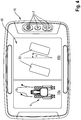
- the representation in Fig. 1 shows a schematic representation of an exported as a tractor 1 agricultural vehicle in a view from above.
- the tractor 1 is designed in a bulldozer design and has a vehicle structure in the form of a vehicle frame 2.
- a caterpillar drive 3 is mounted on both sides with respect to the vehicle longitudinal axis on both sides, that is to say on the left and right sides of the vehicle frame 2, the tractor 1 being supported exclusively via the two caterpillar drives 3 with respect to the ground.
- the tractor 1 is equipped with at least one suitable coupling device in a manner known per se and therefore not shown here, so that a working implement (for example a soil cultivator such as a plow) can be pulled with the tractor 1
- a working implement for example a soil cultivator such as a plow
- the respective caterpillar drive 3 of the tractor 1 has a drive body.
- the drive body is rigidly connected to the vehicle frame 2, for example by a flange connection.
- the drive of trained as Vollraupenhus tractor 1 by means of a differential steering gear or by means of a hydrostatic drive, each crawler drive 3 is assigned a separately controllable hydraulic pump.
- the control of the differential steering gear or the hydrostatic drive is performed by a so-called steer-by-wire device.
- An operator of the tractor 1 generated by the operation of a steering device control pulses, which are converted by the steer-by-wire device into a speed difference for the drive of the right and left crawler tracks 3.
- the use of caterpillar tracks 3 instead of wheels leads to a changed steering and handling of the tractor 1.
- the drive unit of the tractor 1 is designed as a Vollraupenhusgen tractor 1 already reacts to a steering deflection by the operation of the steering device known to rotate about its vertical axis in Stand. This reaction of the tractor 1 can occur unexpectedly for an operator, so that it can lead to accidents.
- a tractor designed as a wheeled vehicle indicates by the wheel deflection as a result of the steering deflection, which curve radius is to be expected in a transition from vehicle standstill into the driving state.
- the tractor 1 can be operated in at least two driving modes to control and regulate the steering.
- the steering and driving behavior in a first driving mode substantially corresponds to that of a wheeled vehicle.
- the steering and driving behavior essentially corresponds to that of a tracked vehicle.
- a tractor 1 associated control device 5 is provided, which allows selection of the first driving mode or the second driving mode. It is provided that the vehicle speed is taken into account as a parameter for an automatic selection of the first driving mode, so that, for example, in a steering angle in the state no rotation of the tractor 1 is about its vertical axis, as is usual for tracked vehicles.
- an operator of the tractor 1 has the opportunity to manually select a driving mode. Since the operator must actively select the second driving mode, in which the driving and steering behavior of the tractor 1 essentially corresponds to that of a bulldozer, the operator knows in advance which driving behavior is to be expected and is not affected by the driving and steering behavior of the tractor 1 surprised. By means of this steering strategy, the operator is given the driving experience of a wheeled vehicle, which increases the driving comfort. In addition, by operating in the first driving mode, the risk of earth accumulation when cornering of tractors 1 in the version as a two-crawler vehicle can be significantly reduced.
- the control device 5 is set up to display the steering angle depending on the selected driving mode.
- the steering angle can be visualized by a controllable by the controller 5 display device 9.
- the operator is the position of imaginary wheels of a wheeled vehicle due to a Steering angle visualized.
- the control device 5 controls the steer-by-wire device in such a way that the driving behavior of a wheeled vehicle is imaged by a corresponding control of the differential steering gear of the tractor 1.
- Tractor 1 describes curve radii corresponding to the steering angle of the imaginary wheels.
- curve radii can be derived mathematically from the equations of Ackermann and are calculated by the control device 5 using suitable algorithms.
- the travel speed of the tractor 1 must be included in the calculation in order to avoid that the tractor 1 is not already rotating about the vertical axis when stationary, although the operator already hits the imaginary wheels by operating the steering device.
- the control device 5 is configured to be able to set the ratio of the steering angle to be reproduced to the detected steering angle of the steering device within certain limits.
- the visualization of the at least two driving modes comprehensive steering strategy is based on in the Fig. 2 to 5 illustrated embodiments explained in more detail.
- Fig. 2 the tractor 1 is shown schematically in a side view.
- the tractor 1 comprises a control device 5, which is connected by a signal and control line 6 with a control terminal 7 arranged in the car 4, which serves for the input and output as well as display of parameters, or screen.
- the control device 5 is connected to at least one actuator 8.
- the actuator 8 may for example be designed as a servomotor.
- the actuator 8 is used to drive at least one mechanical display device 9 for visualizing a steering angle, which is arranged in the front region of the tractor 1.
- the arrangement of the mechanical display device 9 on the tractor 1 is selected such that it lies in the field of view of an operator located in the cabin.
- the at least one mechanical display device 9 comprises a rotation axis 10, on which a display means 11, for example in the form of a pennant, is arranged.
- the display means 11 of the mechanical display device 9 may be designed as a dipstick, directional arrow or flag.
- a paired arrangement of the mechanical display device 9 is provided, for example, on the right and left side on a hood or on the car 4 of the tractor 1.
- the actuator 8 is controlled by the control device 5 in dependence on the selected driving mode. If the tractor 1 is operated in the first driving mode, then the amount of the swivel angle of the indicating means 11 about the rotational axis 10 is based on the maximum steering angle of a comparable wheeled vehicle.
- a parallel to the longitudinal axis of the tractor 1 alignment of the display means 11 is for a straight exit, since there is no steering angle.
- a pivoting about the vertical axis of rotation 10 of the display means 11 indicates the direction and the strength of the steering angle.
- a steering device 12 is provided, which is a conventional steering wheel in the illustrated embodiment.
- the steering device can also be designed as a joystick.
- the control device 5 is operated in the first driving mode, in which the driving and steering behavior essentially corresponds to that of a wheeled vehicle, a projection of a virtual lane 14, 15 onto a windshield 13 of the car 4 takes place in the field of vision of the operator.
- a suitable projection device is arranged in the cabin 4, which receives corresponding control signals from the control device 5.
- the virtual lane 14, 15 is determined by the control device 5 as a function of the driving speed and the steering angle.
- the virtual lane 14 illustrated as a solid line adjusts itself when the tractor 1 is accelerated without the steering device 12 being actuated.
- the dashed line virtual lane 15 results from the acceleration of the tractor 1 and a simultaneous actuation of the steering device 12th
- Fig. 4 shows a running as an operating terminal 16 display device 9, which is arranged in the cabin of the tractor 1.
- the operating terminal 16 comprises a, in particular integrated, screen 18 and one or more operating elements 17.
- the screen 18 may be controllable such that it is subdivided into two separate screen sections 18a, 18b. In this way, during operation in the first driving mode of the tractor 1 in the one screen section 18a of the tractor 1 and the due to the steering angle by operating the steering device 12 adjusting direction of travel can be displayed as arrows 19.
- the other screen portion 18b shows virtual wheels 20 and their steering angle ⁇ resulting from the operation of the steering device 12.
- Fig. 5 the operator terminal 16 is shown, which shows a view of the screen 18 when the tractor 1 is operated in the second driving mode.
- On the screen 18 is a plan view of the tractor 1 is shown.
- the reference numeral 21 designates the high axis of the tractor 1, around which the tractor 1 can rotate in the second driving mode, when a steering lock is present by the operation of the steering device 12, but the tractor 1 is not accelerated simultaneously.
- Arrow 22 indicates the rotation of the tractor 1 about the vertical axis 21.
- the control of the display device 9 by the control device 5 for visualization of the steering and handling of the tractor 1 can be limited in time. For example, can be changed automatically when starting the tractor 1 in the first driving mode, so that it is ensured that the operator is brought to the current steering situation directly to the knowledge. After the transition from vehicle standstill into the driving state has taken place, the visualization can be hidden or switched off. When switching from the first drive mode to the second drive mode, the visualization can be activated automatically.
Description
Die vorliegende Erfindung betrifft ein landwirtschaftliches Fahrzeug gemäß dem Oberbegriff des Anspruches 1. Weiterhin betrifft die Erfindung ein Verfahren zum Betreiben eines landwirtschaftlichen Fahrzeugs gemäß dem Oberbegriff des Anspruches 15.The present invention relates to an agricultural vehicle according to the preamble of claim 1. Furthermore, the invention relates to a method for operating an agricultural vehicle according to the preamble of
Landwirtschaftliche Fahrzeuge, insbesondere Traktoren, umfassend zumindest zwei angetriebene Raupenlaufwerke, die mittels einer Steuerungseinrichtung hinsichtlich ihres Fahr- und Lenkverhaltens ansteuerbar sind, werden üblicherweise durch Differentiallenkgetriebe oder durch unabhängig voneinander angetriebene Raupen gelenkt. Differentialgetriebe werden durch eine sogenannte Steer-by-Wire-Einrichtung angesteuert. Hierbei übermittelt ein Sensor eine Betätigung eines Lenkrades repräsentierende Signale an die Steer-by-Wire-Einrichtung, welche diese Signale in eine Drehzahldifferenz zwischen den angetriebenen Raupenlaufwerken umrechnet, mit der diese angetrieben werden.Agricultural vehicles, in particular tractors, comprising at least two driven crawler tracks, which are controllable by means of a control device with respect to their driving and steering behavior, are usually steered by differential gear or by independently driven caterpillars. Differential gears are controlled by a so-called steer-by-wire device. In this case, a sensor transmits signals representing an actuation of a steering wheel to the steer-by-wire device, which converts these signals into a speed difference between the driven caterpillar drives with which they are driven.
Für eine Bedienperson eines solchen landwirtschaftlichen Fahrzeugs kann sich insbesondere bei einem Übergang von einem Fahrzeugstillstand in den Fahrzustand eine überraschende Situation einstellen, da das mit Voll- oder Halbraupen ausgeführte Fahrzeug anders reagiert, als ein Radfahrzeug. Das Radfahrzeug zeigt der Bedienperson durch den Radeinschlag der lenkbaren Räder an, welcher Kurvenradius bei dem Übergang von dem Fahrzeugstillstand in den Fahrzustand zu erwarten ist. Hingegen lenkt das mit zumindest zwei angetriebenen Raupen ausgestattete Fahrzeug bei einem entsprechenden Lenkausschlag bereits im Stand, so dass es sich auf der Stelle um seine Hochachse dreht.For an operator of such an agricultural vehicle, a surprising situation may arise, in particular when there is a transition from a vehicle standstill into the driving state, since the vehicle executed with full or half-caterpillars reacts differently than a wheeled vehicle. The wheeled vehicle indicates to the operator by the wheel deflection of the steerable wheels, which curve radius is to be expected at the transition from the vehicle standstill into the driving state. On the other hand, the vehicle equipped with at least two driven caterpillars, with a corresponding steering deflection, already steers when stationary, so that it rotates on the spot about its vertical axis.
Aus der
Aufgabe der vorliegenden Erfindung ist es, ein landwirtschaftliches Fahrzeug sowie ein Verfahren zum Betreiben des landwirtschaftlichen Fahrzeugs der eingangs genannten Art bereitzustellen, welches sich durch einen für eine Bedienperson erhöhten Fahrkomfort auszeichnet.Object of the present invention is to provide an agricultural vehicle and a method for operating the agricultural vehicle of the type mentioned above, which is characterized by an increased comfort for an operator comfort.
Diese Aufgabe wird hinsichtlich des Fahrzeugs durch die Merkmale des Anspruches 1 sowie durch ein Verfahren gemäß den Merkmalen des Anspruches 15 gelöst.This object is achieved with regard to the vehicle by the features of claim 1 and by a method according to the features of
Vorteilhafte Weiterbildungen sind Gegenstand der Unteransprüche.Advantageous developments are the subject of the dependent claims.
Gemäß Anspruch 1 wird ein landwirtschaftliches Fahrzeug, insbesondere Traktor, vorgeschlagen, umfassend zumindest zwei angetriebene Raupenlaufwerke, die mittels einer Steuerungseinrichtung hinsichtlich ihres Fahr- und Lenkverhaltens ansteuerbar sind, wobei von einer Lenkvorrichtung aufgrund eines Lenkeinschlages generierte Impulse von der Steuerungseinrichtung zur Ansteuerung der angetriebenen Raupenlaufwerke in einer den Lenkeinschlag repräsentierenden Weise umrechenbar sind, welches dadurch gekennzeichnet ist, dass die Steuerungseinrichtung dazu eingerichtet ist, das Fahrzeug in wenigstens einem ersten Fahrmodus und einem zweiten Fahrmodus zu betreiben, wobei in dem ersten Fahrmodus das Fahr- und Lenkverhalten im Wesentlichen dem eines Radfahrzeuges entspricht und in dem zweiten Fahrmodus das Fahr- und Lenkverhalten im Wesentlichen dem eines Vollraupenfahrzeuges entspricht. Die Bereitstellung zweier Fahrmodi, des ersten Fahrmodus', in welchem sich das Fahrzeug wie ein Radfahrzeug verhält, und des zweiten Fahrmodus', in welchem sich das Fahrzeug wie ein Vollraupenfahrzeug verhält, hat für eine Bedienperson den Vorteil, dass diese das Fahrverhalten des Fahrzeugs gezielt beeinflussen kann und vor einem etwaigen überraschenden Fahrverhalten des Fahrzeugs in Unkenntnis eines bereits bestehenden Lenkeinschlages oder eines getätigten Lenkeinschlages bewahrt wird. Die Größenordnung des Lenkeinschlages kann dabei auch Null betragen, was einer Geradeausfahrt entspräche. Die Steuerungseinrichtung kann dazu eingerichtet sein, den aktuell anliegenden Fahrmodus der Bedienperson zu signalisieren. Somit kann die Bedienperson beispielsweise aktiv entscheiden, ob sie den aktuell anliegenden Fahrmodus beibehalten oder wechseln will. Der Betrieb des Fahrzeugs in dem ersten Fahrmodus hat darüber hinaus den Vorteil, dass die Gefahr von Erdanhäufungen bei Kurvenfahrten des landwirtschaftlichen Fahrzeugs, insbesondere eines Traktors in der Ausführung als Zweiraupenfahrzeug, deutlich verringert werden kann.According to claim 1, an agricultural vehicle, in particular tractor, proposed comprising at least two driven caterpillar drives, which are controllable by means of a control device with regard to their driving and steering behavior, being generated by a steering device due to a steering angle pulses from the control device for controlling the driven caterpillar drives in a manner representing the steering angle are convertible, which is characterized in that the control device is adapted to operate the vehicle in at least a first driving mode and a second driving mode, wherein in the first driving mode, the driving and steering behavior substantially corresponds to that of a wheeled vehicle and in the second driving mode, the driving and steering behavior substantially corresponds to that of a bulldozer vehicle. The provision of two driving modes, the first driving mode in which the vehicle behaves like a wheeled vehicle, and the second driving mode in which the vehicle behaves like a bulldozer, has the advantage for an operator of directing the driving behavior of the vehicle can be affected and is saved from any surprising driving behavior of the vehicle in ignorance of an already existing steering angle or an applied steering angle. The magnitude of the steering angle can also be zero, which would correspond to a straight ahead. The control device may be configured to signal the currently applied driving mode of the operator. Thus, for example, the operator can actively decide whether to maintain or change the currently applied driving mode. The operation of the vehicle in the first driving mode also has the advantage that the risk of earth accumulation when cornering the agricultural vehicle, in particular a tractor in the execution as a two-crawler vehicle can be significantly reduced.
Nach der Erfindung ist die Steuerungseinrichtung dazu eingerichtet sein, in Abhängigkeit von dem gewählten Fahrmodus einen Lenkeinschlag wiederzugeben. Die Bedienperson kann sich anhand eines von der Steuerungseinrichtung wiedergegebenen Lenkeinschlags auf das Verhalten des Fahrzeugs in dem jeweiligen Fahrmodus einstellen, was insbesondere bei einem Übergang von einem Fahrzeugstillstand in den Fahrzustand nach einer längeren Stillstandzeit vorteilhaft ist. Somit kann die Bedienperson erkennen, ob überhaupt ein Lenkeinschlag vorliegt und wie dieser sich in Abhängigkeit von dem eingestellten Fahrmodus auswirkt. Die Auswahlmöglichkeit und Wiedergabe des gewählten Fahrmodus kann der Bedienperson das Fahrgefühl eines Radfahrzeuges vermitteln.According to the invention, the control device is adapted to reproduce a steering angle depending on the selected driving mode. The Operator can adjust based on a reproduced by the control device steering angle on the behavior of the vehicle in the respective driving mode, which is particularly advantageous in a transition from a vehicle standstill in the driving condition after a longer downtime. Thus, the operator can recognize whether there is a steering angle at all and how this affects depending on the set driving mode. The selection and playback of the selected driving mode can convey the driving feeling of a wheeled vehicle to the operator.
Dabei kann ein Lenkeinschlag durch wenigstens eine von der Steuerungseinrichtung ansteuerbare Anzeigeeinrichtung visualisierbar sein. Mittels der wenigstens einen Anzeigeeinrichtung kann der Lenkeinschlag sowie dessen Größenordnung einer Bedienperson zur Ansicht gebracht werden. Insbesondere kann die Bedienperson erkennen, wie sich das Fahrzeug in Abhängigkeit von dem eingestellten Fahrmodus verhalten wird. Eine nur temporäre Visualisierung kann ausreichend sein, um der Bedienperson bei einem Übergang von einem Fahrzeugstillstand in den Fahrzustand eine Orientierung hinsichtlich des aus dem Fahrmodus resultierenden Fahrverhaltens zu geben. Denkbar ist auch eine permanente Visualisierung während des Betriebes des Fahrzeuges. Durch diese Lenkstrategie und Bedienoberfläche wird dem Fahrer das Fahrgefühl eines Radfahrzeugs vermittelt.In this case, a steering angle can be visualized by at least one controllable by the controller display device. By means of the at least one display device, the steering angle and its magnitude of an operator can be brought to the view. In particular, the operator may recognize how the vehicle will behave in response to the set drive mode. Only a temporary visualization can be sufficient to give the operator an orientation with regard to the driving behavior resulting from the driving mode during a transition from a vehicle standstill into the driving state. Also conceivable is a permanent visualization during the operation of the vehicle. This steering strategy and user interface gives the driver the driving experience of a wheeled vehicle.
Hierzu kann ein Lenkeinschlag durch die Darstellung virtueller Räder visualisierbar sein. Die Darstellung des jeweiligen Lenkeinschlages mittels virtueller Räder hat den Vorteil, dass die Bedienperson unmittelbar Kenntnis erlangt, wie sich das Fahrzeug bei einem Lenkeinschlag verhalten wird. Darüber hinaus kann der Bedienperson auf diese Weise der aktuell eingestellte Fahrmodus zur Kenntnis gebracht werden. Die Darstellung virtueller Räder kann zugleich den ersten Fahrmodus symbolisieren, ohne dass es weiterer Anzeigemittel bedarf. Zu diesem Zweck kann die wenigstens eine Anzeigeeinrichtung als ein Bildschirm ausgeführt sein. Anstelle der Darstellung von virtuellen Rädern sind auch andere Formen der Darstellung auf der Anzeigevorrichtung denkbar, um den Lenkeinschlag und den daraus resultierenden Lenkwinkel darzustellen.For this purpose, a steering angle can be visualized by the representation of virtual wheels. The representation of the respective steering angle by means of virtual wheels has the advantage that the operator directly acquires knowledge of how the vehicle will behave when a steering angle. In addition, the operator can be brought in this way the currently set driving mode to the knowledge. The representation of virtual wheels can also symbolize the first driving mode, without the need for further display means. For this purpose, the at least one display device can be designed as a screen. Instead of the representation of virtual wheels are other Forms of representation on the display device conceivable to represent the steering angle and the resulting steering angle.
Alternativ oder zusätzlich kann ein Fahrverhalten aufgrund eines Lenkeinschlags und/oder einer Beschleunigung des Fahrzeugs mittels der Darstellung wenigstens einer virtuellen Fahrspur visualisierbar sein. So kann eine Visualisierung nur einer virtuellen Fahrspur erfolgen, welche lediglich das Fahrverhalten aufgrund eines Lenkeinschlages repräsentiert. Dies ist im Fall des zweiten Fahrmodus' gegeben, da es hierbei bereits bei einem Einschlagen des Lenkrades ohne gleichzeitiges Beschleunigen zu einer Drehung des Fahrzeugs um seine Hochachse kommt. Befindet sich das Fahrzeug im ersten Fahrmodus, so kann mittels der Darstellung wenigstens einer virtuellen Fahrspur das Fahrverhalten des Fahrzeugs in Folge einer Beschleunigung ohne oder mit einem Lenkeinschlag visualisiert werden.Alternatively or additionally, a driving behavior due to a steering angle and / or an acceleration of the vehicle by means of the representation of at least one virtual lane can be visualized. Thus, a visualization of only a virtual lane can be done, which only represents the driving behavior due to a steering angle. This is given in the case of the second driving mode ', since it comes here already at a turning of the steering wheel without simultaneous acceleration to a rotation of the vehicle about its vertical axis. If the vehicle is in the first driving mode, the behavior of the vehicle can be visualized by means of the representation of at least one virtual lane as a result of acceleration without or with a steering angle.
Insbesondere kann die Visualisierung als eine Projektion auf eine Frontscheibe des Fahrzeugs oder auf einem Bildschirm im Inneren der Kabine des Fahrzeugs erfolgen. Bei dem Bildschirm kann es sich beispielsweise um ein in einer Kabine des Fahrzeugs bereits angeordnetes Display einer Bedien- und Steuereinheit des Fahrzeugs oder ein zusätzliches Display handeln, welches von der Steuerungseinrichtung ansteuerbar ist. Die Ausführung der Anzeigeeinrichtung als Projektion auf die Frontscheibe, als so genanntes Head-up-Display, hat den Vorteil, dass die Bedienperson ihre Kopfhaltung beziehungsweise Blickrichtung beibehalten kann, weil die Informationen in das Sichtfeld der Bedienperson projiziert werden.In particular, the visualization can be done as a projection onto a windscreen of the vehicle or on a screen inside the cabin of the vehicle. The screen can be, for example, a display of an operating and control unit of the vehicle already arranged in a cabin of the vehicle or an additional display which can be activated by the control device. The embodiment of the display device as a projection onto the windscreen, as a so-called head-up display, has the advantage that the operator can maintain their head posture or viewing direction because the information is projected into the field of vision of the operator.
Des Weiteren kann der Lenkeinschlag durch wenigstens eine an dem Fahrzeug angeordnete mechanische Anzeigeeinrichtung darstellbar sein, die durch die Steuerungseinrichtung ansteuerbar ist. Die wenigstens eine mechanische Anzeigeeinrichtung steht stellvertretend für imaginäre Räder, welche durch einen Lenkeinschlag in der Weise verstellbar sind, dass diese mechanische Anzeigeeinrichtung das infolge des Lenkeinschlages zu erwartende Fahrverhalten des Fahrzeuges wiedergibt. Bei der wenigstens einen mechanischen Anzeigeeinrichtung kann es sich um richtungsweisende Hilfsmittel, wie beispielsweise Peilstäbe, Wimpel, Fahnen oder dergleichen, handeln, welche im vorderen Bereich des Fahrzeugs im Sichtfeld der Bedienperson angeordnet sind. Hierzu kann die wenigstens eine mechanische Anzeigeeinrichtung durch einen oder mehrere Aktoren um eine vertikale Achse verschwenkbar sein. Der Aktor oder die Aktoren werden hierzu von der Steuerungseinrichtung angesteuert. Die Ansteuerung des Aktors oder der Aktoren erfolgt in Abhängigkeit vom Fahrmodus. Die Schwenkwinkel unterscheiden sich in Abhängigkeit vom jeweiligen Fahrmodus. So kann im ersten Fahrmodus der maximale Schwenkwinkel, der mittels des Aktors ansteuerbar ist, zwischen -60° und 60° bezogen auf die Fahrzeuglängsachse betragen. Hingegen kann der maximale Schwenkwinkel im zweiten Fahrmodus zwischen -90° und 90° betragen, da bei entsprechend em Lenkeinschlag im zweiten Fahrmodus das Drehen um die Hochachse im Stand des Fahrzeugs möglich ist.Furthermore, the steering angle can be represented by at least one arranged on the vehicle mechanical display device which can be controlled by the control device. The at least one mechanical display device is representative of imaginary wheels, which are adjustable by a steering angle in such a way that this mechanical display device the expected as a result of the steering angle behavior of the Vehicle reproduces. The at least one mechanical display device may be directional aids, such as dipsticks, pennants, flags or the like, which are arranged in the front area of the vehicle in the field of vision of the operator. For this purpose, the at least one mechanical display device can be pivoted by one or more actuators about a vertical axis. The actuator or the actuators are controlled by the control device for this purpose. The activation of the actuator or the actuators takes place depending on the driving mode. The swivel angles differ depending on the respective driving mode. Thus, in the first driving mode, the maximum swivel angle, which can be controlled by means of the actuator, can be between -60 ° and 60 ° relative to the vehicle's longitudinal axis. By contrast, the maximum pivoting angle in the second driving mode can be between -90 ° and 90 °, since, with a corresponding steering angle in the second driving mode, it is possible to turn around the vertical axis when the vehicle is stationary.
In bevorzugter Weiterbildung kann vorgesehen sein, dass ein Verhältnis des wiederzugebenden Lenkeinschlags zu dem erfassten Lenkeinschlag des Lenkrades einstellbar ist. Die Einstellbarkeit des Verhältnisses erlaubt es der Bedienperson innerhalb definierter Grenzen bereits geringe Lenkeinschläge stärker zu visualisieren.In a preferred development it can be provided that a ratio of the steering angle to be reproduced to the detected steering angle of the steering wheel is adjustable. The adjustability of the ratio allows the operator within a defined limits to visualize even lower steering angles stronger.
Bevorzugt kann bei einem Betrieb des Fahrzeugs in dem ersten Fahrmodus ein von der Steuerungseinrichtung ansteuerbarer Mindestkurvenradius dem eines Radfahrzeuges mit einem Radstand entsprechen, der dem Radstand der virtuellen Räder entspricht. Hierzu können die Kurvenradien mittels der Steuerungseinrichtung mathematisch herleitbar sein.In an operation of the vehicle in the first driving mode, a minimum curve radius which can be controlled by the control device can preferably correspond to that of a wheeled vehicle having a wheelbase which corresponds to the wheelbase of the virtual wheels. For this purpose, the curve radii can be derived mathematically by means of the control device.
Vorteilhafterweise kann die Steuerungseinrichtung dazu eingerichtet sein, dass Lenkverhalten in Abhängigkeit von zumindest einem Betriebsparameter des Fahrzeugs und dem gewählten Fahrmodus anzusteuern. Als Betriebsparameter sollte die Fahrgeschwindigkeit Eingang finden, da ein Lenkeinschlag im ersten Fahrmodus bei gleichzeitigem Stillstand des Fahrzeugs nicht zu einem Drehen um dessen Hochachse führen soll.Advantageously, the control device can be set up to control the steering behavior as a function of at least one operating parameter of the vehicle and the selected driving mode. As operating parameters, the driving speed should be considered as a steering angle in the first Driving mode with simultaneous stop of the vehicle should not lead to a rotation about its vertical axis.
Vorzugsweise kann die Steuerungseinrichtung dazu eingerichtet sein, dass ein Fahrmodus manuell auswählbar ist. Hierzu kann die Steuerungseinrichtung mit einer in der Kabine angeordneten Eingabevorrichtung steuerungstechnisch verbunden sein, mittels der von der Bedienperson zwischen den beiden Fahrmodi hin und her geschaltet werden kann.Preferably, the control device can be configured such that a driving mode can be selected manually. For this purpose, the control device can be connected in terms of control technology to an input device arranged in the cab, by means of which it is possible to switch back and forth between the two driving modes by the operator.
Bevorzugt kann die Steuerungseinrichtung dazu eingerichtet sein, bei einem Übergang in einen dem Stillstand des Fahrzeugs entsprechenden Fahrzustand automatisch in den ersten Fahrmodus zu wechseln. Als Fahrzeugstillstand kommen beispielsweise das Reduzieren der Fahrgeschwindigkeit auf null, insbesondere über einen definierbaren Zeitraum hinaus, oder das Abschalten des Antriebes des Fahrzeugs in Betracht. Auf diese Weise kann verhindert werden, dass die Bedienperson von einem nicht erwarteten Fahrverhalten überrascht wird.Preferably, the control device may be configured to automatically change to the first driving mode when changing over to a driving state corresponding to the standstill of the vehicle. As a vehicle standstill come, for example, reducing the vehicle speed to zero, in particular over a definable period of time, or switching off the drive of the vehicle into consideration. In this way it can be prevented that the operator is surprised by an unexpected driving behavior.
Insbesondere kann die Steuerungseinrichtung dazu eingerichtet sein, die Raupenlaufwerke mittels eines Differentiallenkgetriebes anzusteuern. Die Steuerungseinrichtung steuert das Differentiallenkgetriebe in der Weise an, so dass das Fahrzeug entsprechend des Lenkeinschlages der imaginären oder virtuellen Räder Kurvenradien beschreibt, die dem Fahrverhalten eines Radfahrzeuges entsprechen.In particular, the control device may be configured to control the caterpillar drives by means of a differential steering gear. The control device controls the differential steering gear in such a way so that the vehicle according to the steering angle of the imaginary or virtual wheels describes curve radii that correspond to the handling of a wheeled vehicle.
Alternativ kann die Steuerungseinrichtung dazu eingerichtet sein, die Raupenlaufwerke unabhängig voneinander anzusteuern. Auch in diesem Fall sorgt die Steuerungseinrichtung dafür, dass in dem ersten Fahrmodus das Fahrzeug ein Fahrverhalten an den Tag legt, welches dem eines Radfahrzeuges entspricht.Alternatively, the control device can be set up to control the caterpillar drives independently of one another. In this case too, the control device ensures that in the first driving mode the vehicle exhibits a driving behavior which corresponds to that of a wheeled vehicle.
Gemäß Anspruch 15 wird ein Verfahren zum Betreiben eines landwirtschaftlichen Fahrzeugs vorgeschlagen, welches zumindest zwei angetriebene Raupenlaufwerke, die mittels einer Steuerungseinrichtung hinsichtlich ihres Fahr- und Lenkverhaltens angesteuert werden, umfasst, wobei von einer Lenkvorrichtung aufgrund eines Lenkeinschlages generierte Impulse von der Steuerungseinrichtung zur Ansteuerung der angetriebenen Raupenlaufwerke in einer den Lenkeinschlag repräsentierenden Weise umgerechnet werden. Das Verfahren ist dadurch gekennzeichnet, dass wobei in dem ersten Fahrmodus das Fahrzeug dem Fahr- und Lenkverhalten im Wesentlichen eines Radfahrzeuges entsprechend angesteuert wird und in dem zweiten Fahrmodus das Fahrzeug dem Fahr- und Lenkverhalten im Wesentlichen eines Vollraupenfahrzeuges entsprechend angesteuert wird. Mittels des Verfahrens ist ein an das Fahrverhalten von reinen Radfahrzeugen angenähertes Fahrverhalten von Raupenfahrzeugen erreichbar, wodurch eine erhöhte Benutzerfreundlichkeit erreicht werden kann.According to
Die vorliegende Erfindung wird nachstehend anhand von in den Zeichnungen dargestellten Ausführungsbeispielen näher erläutert.The present invention will be explained below with reference to exemplary embodiments illustrated in the drawings.
Es zeigen:
- Fig. 1
- eine schematische Darstellung eines landwirtschaftlichen Fahrzeugs in einer Ansicht von oben;
- Fig. 2
- eine schematische Darstellung des landwirtschaftlichen Fahrzeugs in einer Seitenansicht;
- Fig. 3
- eine schematische Innenansicht einer Kabine des landwirtschaftlichen Fahrzeugs gemäß
Fig. 1 ; - Fig. 4
- eine Anzeigevorrichtung, welche das Fahrzeug in einem ersten Fahrmodus visualisiert;
- Fig. 5
- eine Anzeigevorrichtung, welche das Fahrzeug in einem zweiten Fahrmodus visualisiert.
- Fig. 1
- a schematic representation of an agricultural vehicle in a view from above;
- Fig. 2
- a schematic representation of the agricultural vehicle in a side view;
- Fig. 3
- a schematic interior view of a cabin of the agricultural vehicle according to
Fig. 1 ; - Fig. 4
- a display device that visualizes the vehicle in a first driving mode;
- Fig. 5
- a display device that visualizes the vehicle in a second drive mode.
Die Darstellung in
Die Ansteuerung des Differentiallenkgetriebes oder des hydrostatischen Fahrantriebs erfolgt durch eine sogenannte Steer-by-Wire-Einrichtung. Eine Bedienperson des Traktors 1 erzeugt durch die Betätigung einer Lenkvorrichtung Steuerimpulse, welche von der Steer-by-Wire-Einrichtung in eine Drehzahldifferenz für den Antrieb der rechts- und linksseitigen Raupenlaufwerke 3 umgerechnet werden. Die Verwendung von Raupenlaufwerken 3 anstelle von Rädern führt zu einem veränderten Lenk- und Fahrverhalten des Traktors 1. Bei laufendem Antriebsaggregat des Traktors 1 reagiert der als Vollraupenfahrzeug ausgebildete Traktor 1 bereits auf einen Lenkausschlag durch die Betätigung der Lenkvorrichtung bekanntermaßen mit einer Drehung um seine Hochachse im Stand. Diese Reaktion des Traktors 1 kann für eine Bedienperson unerwartet auftreten, so dass es zu Unfällen kommen kann. Hingegen zeigt ein als Radfahrzeug ausgeführter Traktor durch den Radeinschlag infolge des Lenkausschlages an, welcher Kurvenradius bei einem Übergang vom Fahrzeugstillstand in den Fahrzustand zu erwarten ist.The control of the differential steering gear or the hydrostatic drive is performed by a so-called steer-by-wire device. An operator of the tractor 1 generated by the operation of a steering device control pulses, which are converted by the steer-by-wire device into a speed difference for the drive of the right and left crawler tracks 3. The use of
Um den Bedienkomfort des als Vollraupenfahrzeug ausgeführten Traktors 1 zu verbessern, ist es vorgesehen, dass der Traktor 1 zur Steuerung und Regelung der Lenkung in zumindest zwei Fahrmodi betreibbar ist. Das Lenk- und Fahrverhalten entspricht in einem ersten Fahrmodus im Wesentlichen dem eines Radfahrzeuges. In einem zweiten Fahrmodus entspricht das Lenk- und Fahrverhalten im Wesentlichen dem eines Raupenfahrzeuges. Hierzu ist eine dem Traktor 1 zugeordnete Steuerungseinrichtung 5 vorgesehen, welche eine Auswahl des ersten Fahrmodus oder des zweiten Fahrmodus erlaubt. Dabei ist vorgesehen, dass die Fahrzeuggeschwindigkeit als Parameter für eine automatische Auswahl des ersten Fahrmodus berücksichtigt wird, so dass beispielsweise bei einem Lenkeinschlag im Stand keine Drehung des Traktors 1 um seine Hochachse erfolgt, wie es für Raupenfahrzeuge üblich ist. Darüber hinaus hat eine Bedienperson des Traktors 1 die Möglichkeit, einen Fahrmodus manuell auszuwählen. Da die Bedienperson den zweiten Fahrmodus, in dem das Fahr- und Lenkverhalten des Traktors 1 im Wesentlichen dem eines Vollraupenfahrzeuges entspricht, aktiv anwählen muss, weiß die Bedienperson im Vorfeld, welches Fahrverhalten zu erwarten ist und wird nicht von dem Fahr- und Lenkverhalten des Traktors 1 überrascht. Mittels dieser Lenkstrategie wird der Bedienperson das Fahrgefühl eines Radfahrzeugs vermittelt, was den Fahrkomfort erhöht. Zudem kann durch den Betrieb im ersten Fahrmodus auch die Gefahr von Erdanhäufungen bei Kurvenfahrten von Traktoren 1 in der Ausführung als Zweiraupenfahrzeug deutlich verringert werden.In order to improve the operating comfort of the tractor 1 designed as a bulldozer vehicle, it is provided that the tractor 1 can be operated in at least two driving modes to control and regulate the steering. The steering and driving behavior in a first driving mode substantially corresponds to that of a wheeled vehicle. In a second driving mode, the steering and driving behavior essentially corresponds to that of a tracked vehicle. For this purpose, a tractor 1 associated control device 5 is provided, which allows selection of the first driving mode or the second driving mode. It is provided that the vehicle speed is taken into account as a parameter for an automatic selection of the first driving mode, so that, for example, in a steering angle in the state no rotation of the tractor 1 is about its vertical axis, as is usual for tracked vehicles. In addition, an operator of the tractor 1 has the opportunity to manually select a driving mode. Since the operator must actively select the second driving mode, in which the driving and steering behavior of the tractor 1 essentially corresponds to that of a bulldozer, the operator knows in advance which driving behavior is to be expected and is not affected by the driving and steering behavior of the tractor 1 surprised. By means of this steering strategy, the operator is given the driving experience of a wheeled vehicle, which increases the driving comfort. In addition, by operating in the first driving mode, the risk of earth accumulation when cornering of tractors 1 in the version as a two-crawler vehicle can be significantly reduced.
Um der Bedienperson das Fahrverhalten aufgrund des gewählten Fahrmodus' transparent zu machen, ist die Steuerungseinrichtung 5 dazu eingerichtet, in Abhängigkeit von dem gewählten Fahrmodus den Lenkeinschlag wiederzugeben. Hierzu ist der Lenkeinschlag durch eine von der Steuerungseinrichtung 5 ansteuerbare Anzeigeeinrichtung 9 visualisierbar. Zu diesem Zweck wird der Bedienperson die Stellung imaginärer Räder eines Radfahrzeuges infolge eines Lenkeinschlages visualisiert. Bei einem Betrieb im ersten Fahrmodus steuert die Steuerungseinrichtung 5 die Steer-by-Wire-Einrichtung in der Weise an, dass durch eine entsprechende Ansteuerung des Differentiallenkgetriebes des Traktors 1 das Fahrverhalten eines Radfahrzeuges abgebildet wird. Der Traktor 1 beschreibt dabei Kurvenradien entsprechend des Lenkeinschlages der imaginären Räder. Diese Kurvenradien sind mathematisch einfach aus den Gleichungen von Ackermann herleitbar und werden durch geeignete Algorithmen von der Steuerungseinrichtung 5 berechnet. Für die Ansteuerung der Differentiallenkung muss die Fahrgeschwindigkeit des Traktors 1 zwingend in die Berechnung mit einbezogen werden, um zu vermeiden, dass der Traktor 1 nicht bereits im Stillstand um die Hochachse dreht, obwohl die Bedienperson durch Betätigung der Lenkvorrichtung bereits die imaginären Räder einschlägt. Die Steuerungseinrichtung 5 ist dazu eingerichtet, das Verhältnis des wiederzugebenden Lenkeinschlags zu dem erfassten Lenkeinschlag der Lenkvorrichtung innerhalb bestimmter Grenzen einstellen zu können.In order to make the driver's driving behavior transparent on the basis of the selected driving mode, the control device 5 is set up to display the steering angle depending on the selected driving mode. For this purpose, the steering angle can be visualized by a controllable by the controller 5
Nachfolgend wird die Visualisierung der mindestens zwei Fahrmodi umfassenden Lenkstrategie anhand von in den
In
Die Darstellung in
In
Die Ansteuerung der Anzeigeeinrichtung 9 durch die Steuerungseinrichtung 5 zur Visualisierung des Lenk- und Fahrverhaltens des Traktors 1 kann zeitlich begrenzt erfolgen. Beispielsweise kann beim Starten des Traktors 1 automatisch in den ersten Fahrmodus gewechselt werden, so dass sichergestellt ist, dass der Bedienperson die aktuelle Lenksituation unmittelbar zur Kenntnis gebracht wird. Nachdem der Übergang vom Fahrzeugstillstand in den Fahrzustand erfolgt ist, kann die Visualisierung ausgeblendet beziehungsweise abgeschaltet werden. Bei einem Wechsel von dem ersten Fahrmodus in den zweiten Fahrmodus kann die Visualisierung automatisch aktiviert werden.The control of the
- 11
- Traktortractor
- 22
- Rahmenframe
- 33
- RaupenlaufwerkCaterpillar tracks
- 44
- Kabinecabin
- 55
- Steuerungseinrichtungcontrol device
- 66
- Signal- und SteuerleitungSignal and control line
- 77
- Bedienterminaloperating terminal
- 88th
- Aktoractuator
- 99
- Anzeigeeinrichtungdisplay
- 1010
- Drehachseaxis of rotation
- 1111
- Anzeigemitteldisplay means
- 1212
- Lenkvorrichtungsteering device
- 1313
- Frontscheibewindscreen
- 1414
- Virtuelle FahrspurVirtual lane
- 1515
- Virtuelle FahrspurVirtual lane
- 1616
- Bedienterminaloperating terminal
- 1717
- Bedienelementoperating element
- 1818
- Bildschirmscreen
- 18a18a
- Bildschirmabschnittscreen section
- 18b18b
- Bildschirmabschnittscreen section
- 1919
- Pfeilarrow
- 2020
- Virtuelles RadVirtual Wheel
- 2121
- Hochachse des Traktors 1Vertical axis of the tractor 1
- 2222
- Pfeilarrow
- αα
- Lenkwinkelsteering angle
Claims (14)
- An agricultural vehicle (1) including at least two driven track-laying units (3) actuable by means of a control device (5) in respect of their travel and steering behaviour, wherein pulses generated by a steering device (12) on the basis of a steering angle can be converted by the control device (5) for actuation of the driven track-laying units (3) in a manner representing the steering angle, characterised in that the control device (5) is adapted to operate the vehicle (1) in at least a first travel mode and a second travel mode, wherein in the first travel mode the travel and steering behaviour substantially corresponds to that of a wheeled vehicle and in the second travel mode the travel and steering behaviour substantially corresponds to that of a fully track-laying vehicle, wherein the control device (5) is adapted to reproduce a steering angle in dependence on the selected travel mode.
- An agricultural vehicle (1) according to claim 1 characterised in that a steering angle can be visualised by a display device (9) actuable by the control device (5).
- An agricultural vehicle (1) according to claim 1 or claim 2 characterised in that a steering angle can be visualised by the representation of virtual wheels (20).
- An agricultural vehicle (1) according to one of claims 1 to 3 characterised in that a travel behaviour can be visualised on the basis of a steering angle and/or an acceleration of the vehicle (1) by means of the representation of at least one virtual travel path (14, 15).
- An agricultural vehicle (1) according to one of claims 2 to 4 characterised in that the visualisation is in the form of a projection on to a windscreen (13) of the vehicle (1) or on a display screen (17, 18) in the interior of the cab (4) of the vehicle (1).
- An agricultural vehicle (1) according to claim 1 characterised in that the steering angle can be represented by at least one mechanical display device (9, 11) which is arranged on the vehicle (1) and which is actuable by the control device (5).
- An agricultural vehicle (1) according to one of claims 1 to 5 characterised in that a ratio of the steering angle to be reproduced to the detected steering angle of the steering wheel is adjustable.
- An agricultural vehicle (1) according to one of claims 2 to 6 characterised in that in operation of the vehicle (1) in the first travel mode a minimum curve radius actuable by the control device (5) corresponds to that of a wheeled vehicle with a wheelbase which corresponds to the wheelbase of the virtual wheels (20).
- An agricultural vehicle (1) according to one of claims 1 to 7 characterised in that the control device (5) is adapted to actuate the steering behaviour in dependence on at least one operating parameter of the vehicle (1) and the selected travel mode.
- An agricultural vehicle (1) according to one of claims 1 to 9 characterised in that the control device (5) is adapted for a travel mode to be manually selectable.
- An agricultural vehicle (1) according to one of claims 1 to 9 characterised in that the control device (5) is adapted automatically to change into the first travel mode in a transition to a vehicle state corresponding to the vehicle (1) being stopped.
- An agricultural vehicle (1) according to one of claims 1 to 11 characterised in that the control device (5) is adapted to actuate the track-laying units (3) by means of a differential transmission.
- An agricultural vehicle (1) according to one of claims 1 to 11 characterised in that the control device (5) is adapted to actuate the track-laying units (3) independently of each other.
- A method of operating an agricultural vehicle (1) including at least two driven track-laying units (3) which are actuated by means of a control device (5) in respect of their travel and steering behaviour, wherein pulses generated by a steering device (12) on the basis of a steering angle are converted by the control device (5) for actuation of the driven track-laying units (3) in a manner representing the steering angle, characterised in that the vehicle (1) is operated in at least a first travel mode and a second travel mode, wherein in the first travel mode the vehicle (1) is actuated corresponding to the travel and steering behaviour substantially of a wheeled vehicle and in the second travel mode the vehicle (1) is actuated corresponding to the travel and steering behaviour substantially of a fully track-laying vehicle, wherein the control device (5) is adapted to reproduce a steering angle in dependence on the selected travel mode.
Applications Claiming Priority (1)
| Application Number | Priority Date | Filing Date | Title |
|---|---|---|---|
| DE102016106788.1A DE102016106788A1 (en) | 2016-04-13 | 2016-04-13 | Agricultural vehicle |
Publications (2)
| Publication Number | Publication Date |
|---|---|
| EP3231688A1 EP3231688A1 (en) | 2017-10-18 |
| EP3231688B1 true EP3231688B1 (en) | 2019-07-10 |
Family
ID=58265885
Family Applications (1)
| Application Number | Title | Priority Date | Filing Date |
|---|---|---|---|
| EP17160080.2A Active EP3231688B1 (en) | 2016-04-13 | 2017-03-09 | Agricultural vehicle |
Country Status (2)
| Country | Link |
|---|---|
| EP (1) | EP3231688B1 (en) |
| DE (1) | DE102016106788A1 (en) |
Family Cites Families (5)
| Publication number | Priority date | Publication date | Assignee | Title |
|---|---|---|---|---|
| WO2003026385A1 (en) * | 2001-09-07 | 2003-04-03 | Dillon Ben N | Articulated combine |
| US6298931B1 (en) | 1999-12-09 | 2001-10-09 | Deere & Company | Tracked vehicle steering control system with non-centered steering wheel |
| DE10033261A1 (en) * | 2000-07-11 | 2002-01-24 | Macmoter Spa | vehicle |
| WO2008042244A2 (en) * | 2006-09-29 | 2008-04-10 | Volvo Construction Equipment Ab | Propulsion and steering system for a road milling machine |
| US20130158802A1 (en) * | 2011-12-16 | 2013-06-20 | Caterpillar Paving Products Inc. | Steering System for Crawler Track Machine |
-
2016
- 2016-04-13 DE DE102016106788.1A patent/DE102016106788A1/en not_active Withdrawn
-
2017
- 2017-03-09 EP EP17160080.2A patent/EP3231688B1/en active Active
Non-Patent Citations (1)
| Title |
|---|
| None * |
Also Published As
| Publication number | Publication date |
|---|---|
| DE102016106788A1 (en) | 2017-10-19 |
| EP3231688A1 (en) | 2017-10-18 |
Similar Documents
| Publication | Publication Date | Title |
|---|---|---|
| DE102006048947B4 (en) | Control unit and method for adjusting a trailer coupled to a vehicle | |
| EP2388180B1 (en) | Reversing aid device for regulating a reverse motion of a road vehicle train | |
| DE102016214433B4 (en) | Distraction-free remote control of a motor vehicle with a parking assistance system | |
| EP2879938B1 (en) | Method and device to shunt a trailer | |
| DE102007029413B4 (en) | Method for carrying out a steering operation in a vehicle with a trailer when reversing | |
| EP2014504B1 (en) | Operational device for controlling at least one variable of an agricultural or industrial truck | |
| DE102012205416B4 (en) | Trailer path curvature control for trailer backup assist | |
| EP3418159A2 (en) | Method for operating a park assisting device of a motor vehicle with combined view of transparent trailer and environment | |
| DE102005004394B4 (en) | Return assistant | |
| DE102005043467A1 (en) | Reverse drive assistance system for vehicle combination, has input device with adjusting unit for influencing force acting on adjusting lever to give haptic feedback signal about realizability and dangerousness of parameters to driver | |
| EP2014503B1 (en) | Operational device for controlling at least one variable of an agricultural or industrial truck | |
| DE102005043466A1 (en) | Reversing aid system for assisting driver of towing vehicle-trailer-combination, has image displaying device displaying movement path of towing vehicle-trailer-combination and movement path of trailer in common image | |
| EP0970875B1 (en) | Steering system for vehicles | |
| DE102016120203A1 (en) | ILLUMINATED VEHICLE MANAGEMENT PUSH BUTTON | |
| DE102013000198A1 (en) | Method for ranking of car/trailer combination, involves performing maneuvering of towing vehicle with active steering assistance while maintaining predetermined direction of travel up to final parking position | |
| DE102013016342A1 (en) | Method for assisting reversing a team, driver assistance system | |
| EP2583544A1 (en) | Visualisation device | |
| EP3016837B1 (en) | Parking assistance system and method for controlling a parking assistance system for a vehicle | |
| DE102016116913A1 (en) | Multifunction inclination switch for parking function | |
| DE102013003853A1 (en) | Method, control system and braking system for controlling the backward maneuvering of a trailer vehicle | |
| WO2013178476A1 (en) | Manoeuvring assistance system | |
| DE102015005975B4 (en) | Method for operating a transverse guidance system of a motor vehicle and motor vehicle | |
| WO2020216538A1 (en) | Method for operating a driver assistance system of an at least partially electrically operable motor vehicle for controlling four wheels, driver assistance system, and motor vehicle | |
| DE102010052293A1 (en) | Driver assistance system adjusting method for vehicle, involves activating functional groups based on representation of sub elements of graphic base element, where sub-functions of driver assistance modules are associated with groups | |
| EP3231688B1 (en) | Agricultural vehicle |
Legal Events
| Date | Code | Title | Description |
|---|---|---|---|
| PUAI | Public reference made under article 153(3) epc to a published international application that has entered the european phase |
Free format text: ORIGINAL CODE: 0009012 |
|
| STAA | Information on the status of an ep patent application or granted ep patent |
Free format text: STATUS: THE APPLICATION HAS BEEN PUBLISHED |
|
| AK | Designated contracting states |
Kind code of ref document: A1 Designated state(s): AL AT BE BG CH CY CZ DE DK EE ES FI FR GB GR HR HU IE IS IT LI LT LU LV MC MK MT NL NO PL PT RO RS SE SI SK SM TR |
|
| AX | Request for extension of the european patent |
Extension state: BA ME |
|
| STAA | Information on the status of an ep patent application or granted ep patent |
Free format text: STATUS: REQUEST FOR EXAMINATION WAS MADE |
|
| 17P | Request for examination filed |
Effective date: 20180418 |
|
| RBV | Designated contracting states (corrected) |
Designated state(s): AL AT BE BG CH CY CZ DE DK EE ES FI FR GB GR HR HU IE IS IT LI LT LU LV MC MK MT NL NO PL PT RO RS SE SI SK SM TR |
|
| GRAP | Despatch of communication of intention to grant a patent |
Free format text: ORIGINAL CODE: EPIDOSNIGR1 |
|
| STAA | Information on the status of an ep patent application or granted ep patent |
Free format text: STATUS: GRANT OF PATENT IS INTENDED |
|
| INTG | Intention to grant announced |
Effective date: 20190411 |
|
| GRAS | Grant fee paid |
Free format text: ORIGINAL CODE: EPIDOSNIGR3 |
|
| GRAA | (expected) grant |
Free format text: ORIGINAL CODE: 0009210 |
|
| STAA | Information on the status of an ep patent application or granted ep patent |
Free format text: STATUS: THE PATENT HAS BEEN GRANTED |
|
| AK | Designated contracting states |
Kind code of ref document: B1 Designated state(s): AL AT BE BG CH CY CZ DE DK EE ES FI FR GB GR HR HU IE IS IT LI LT LU LV MC MK MT NL NO PL PT RO RS SE SI SK SM TR |
|
| REG | Reference to a national code |
Ref country code: GB Ref legal event code: FG4D Free format text: NOT ENGLISH |
|
| REG | Reference to a national code |
Ref country code: CH Ref legal event code: EP Ref country code: AT Ref legal event code: REF Ref document number: 1153280 Country of ref document: AT Kind code of ref document: T Effective date: 20190715 |
|
| REG | Reference to a national code |
Ref country code: DE Ref legal event code: R096 Ref document number: 502017001705 Country of ref document: DE |
|
| REG | Reference to a national code |
Ref country code: IE Ref legal event code: FG4D Free format text: LANGUAGE OF EP DOCUMENT: GERMAN |
|
| REG | Reference to a national code |
Ref country code: NL Ref legal event code: MP Effective date: 20190710 |
|
| REG | Reference to a national code |
Ref country code: LT Ref legal event code: MG4D |
|
| PG25 | Lapsed in a contracting state [announced via postgrant information from national office to epo] |
Ref country code: NO Free format text: LAPSE BECAUSE OF FAILURE TO SUBMIT A TRANSLATION OF THE DESCRIPTION OR TO PAY THE FEE WITHIN THE PRESCRIBED TIME-LIMIT Effective date: 20191010 Ref country code: NL Free format text: LAPSE BECAUSE OF FAILURE TO SUBMIT A TRANSLATION OF THE DESCRIPTION OR TO PAY THE FEE WITHIN THE PRESCRIBED TIME-LIMIT Effective date: 20190710 Ref country code: PT Free format text: LAPSE BECAUSE OF FAILURE TO SUBMIT A TRANSLATION OF THE DESCRIPTION OR TO PAY THE FEE WITHIN THE PRESCRIBED TIME-LIMIT Effective date: 20191111 Ref country code: LT Free format text: LAPSE BECAUSE OF FAILURE TO SUBMIT A TRANSLATION OF THE DESCRIPTION OR TO PAY THE FEE WITHIN THE PRESCRIBED TIME-LIMIT Effective date: 20190710 Ref country code: BG Free format text: LAPSE BECAUSE OF FAILURE TO SUBMIT A TRANSLATION OF THE DESCRIPTION OR TO PAY THE FEE WITHIN THE PRESCRIBED TIME-LIMIT Effective date: 20191010 Ref country code: HR Free format text: LAPSE BECAUSE OF FAILURE TO SUBMIT A TRANSLATION OF THE DESCRIPTION OR TO PAY THE FEE WITHIN THE PRESCRIBED TIME-LIMIT Effective date: 20190710 Ref country code: SE Free format text: LAPSE BECAUSE OF FAILURE TO SUBMIT A TRANSLATION OF THE DESCRIPTION OR TO PAY THE FEE WITHIN THE PRESCRIBED TIME-LIMIT Effective date: 20190710 Ref country code: FI Free format text: LAPSE BECAUSE OF FAILURE TO SUBMIT A TRANSLATION OF THE DESCRIPTION OR TO PAY THE FEE WITHIN THE PRESCRIBED TIME-LIMIT Effective date: 20190710 |
|
| PG25 | Lapsed in a contracting state [announced via postgrant information from national office to epo] |
Ref country code: AL Free format text: LAPSE BECAUSE OF FAILURE TO SUBMIT A TRANSLATION OF THE DESCRIPTION OR TO PAY THE FEE WITHIN THE PRESCRIBED TIME-LIMIT Effective date: 20190710 Ref country code: GR Free format text: LAPSE BECAUSE OF FAILURE TO SUBMIT A TRANSLATION OF THE DESCRIPTION OR TO PAY THE FEE WITHIN THE PRESCRIBED TIME-LIMIT Effective date: 20191011 Ref country code: ES Free format text: LAPSE BECAUSE OF FAILURE TO SUBMIT A TRANSLATION OF THE DESCRIPTION OR TO PAY THE FEE WITHIN THE PRESCRIBED TIME-LIMIT Effective date: 20190710 Ref country code: IS Free format text: LAPSE BECAUSE OF FAILURE TO SUBMIT A TRANSLATION OF THE DESCRIPTION OR TO PAY THE FEE WITHIN THE PRESCRIBED TIME-LIMIT Effective date: 20191110 Ref country code: RS Free format text: LAPSE BECAUSE OF FAILURE TO SUBMIT A TRANSLATION OF THE DESCRIPTION OR TO PAY THE FEE WITHIN THE PRESCRIBED TIME-LIMIT Effective date: 20190710 Ref country code: LV Free format text: LAPSE BECAUSE OF FAILURE TO SUBMIT A TRANSLATION OF THE DESCRIPTION OR TO PAY THE FEE WITHIN THE PRESCRIBED TIME-LIMIT Effective date: 20190710 |
|
| PG25 | Lapsed in a contracting state [announced via postgrant information from national office to epo] |
Ref country code: TR Free format text: LAPSE BECAUSE OF FAILURE TO SUBMIT A TRANSLATION OF THE DESCRIPTION OR TO PAY THE FEE WITHIN THE PRESCRIBED TIME-LIMIT Effective date: 20190710 |
|
| PG25 | Lapsed in a contracting state [announced via postgrant information from national office to epo] |
Ref country code: RO Free format text: LAPSE BECAUSE OF FAILURE TO SUBMIT A TRANSLATION OF THE DESCRIPTION OR TO PAY THE FEE WITHIN THE PRESCRIBED TIME-LIMIT Effective date: 20190710 Ref country code: DK Free format text: LAPSE BECAUSE OF FAILURE TO SUBMIT A TRANSLATION OF THE DESCRIPTION OR TO PAY THE FEE WITHIN THE PRESCRIBED TIME-LIMIT Effective date: 20190710 Ref country code: IT Free format text: LAPSE BECAUSE OF FAILURE TO SUBMIT A TRANSLATION OF THE DESCRIPTION OR TO PAY THE FEE WITHIN THE PRESCRIBED TIME-LIMIT Effective date: 20190710 Ref country code: PL Free format text: LAPSE BECAUSE OF FAILURE TO SUBMIT A TRANSLATION OF THE DESCRIPTION OR TO PAY THE FEE WITHIN THE PRESCRIBED TIME-LIMIT Effective date: 20190710 Ref country code: EE Free format text: LAPSE BECAUSE OF FAILURE TO SUBMIT A TRANSLATION OF THE DESCRIPTION OR TO PAY THE FEE WITHIN THE PRESCRIBED TIME-LIMIT Effective date: 20190710 |
|
| PG25 | Lapsed in a contracting state [announced via postgrant information from national office to epo] |
Ref country code: SK Free format text: LAPSE BECAUSE OF FAILURE TO SUBMIT A TRANSLATION OF THE DESCRIPTION OR TO PAY THE FEE WITHIN THE PRESCRIBED TIME-LIMIT Effective date: 20190710 Ref country code: SM Free format text: LAPSE BECAUSE OF FAILURE TO SUBMIT A TRANSLATION OF THE DESCRIPTION OR TO PAY THE FEE WITHIN THE PRESCRIBED TIME-LIMIT Effective date: 20190710 Ref country code: IS Free format text: LAPSE BECAUSE OF FAILURE TO SUBMIT A TRANSLATION OF THE DESCRIPTION OR TO PAY THE FEE WITHIN THE PRESCRIBED TIME-LIMIT Effective date: 20200224 Ref country code: CZ Free format text: LAPSE BECAUSE OF FAILURE TO SUBMIT A TRANSLATION OF THE DESCRIPTION OR TO PAY THE FEE WITHIN THE PRESCRIBED TIME-LIMIT Effective date: 20190710 |
|
| REG | Reference to a national code |
Ref country code: DE Ref legal event code: R097 Ref document number: 502017001705 Country of ref document: DE |
|
| PLBE | No opposition filed within time limit |
Free format text: ORIGINAL CODE: 0009261 |
|
| STAA | Information on the status of an ep patent application or granted ep patent |
Free format text: STATUS: NO OPPOSITION FILED WITHIN TIME LIMIT |
|
| PG2D | Information on lapse in contracting state deleted |
Ref country code: IS |
|
| 26N | No opposition filed |
Effective date: 20200603 |
|
| PG25 | Lapsed in a contracting state [announced via postgrant information from national office to epo] |
Ref country code: SI Free format text: LAPSE BECAUSE OF FAILURE TO SUBMIT A TRANSLATION OF THE DESCRIPTION OR TO PAY THE FEE WITHIN THE PRESCRIBED TIME-LIMIT Effective date: 20190710 |
|
| PG25 | Lapsed in a contracting state [announced via postgrant information from national office to epo] |
Ref country code: MC Free format text: LAPSE BECAUSE OF FAILURE TO SUBMIT A TRANSLATION OF THE DESCRIPTION OR TO PAY THE FEE WITHIN THE PRESCRIBED TIME-LIMIT Effective date: 20190710 |
|
| REG | Reference to a national code |
Ref country code: CH Ref legal event code: PL |
|
| PG25 | Lapsed in a contracting state [announced via postgrant information from national office to epo] |
Ref country code: LU Free format text: LAPSE BECAUSE OF NON-PAYMENT OF DUE FEES Effective date: 20200309 |
|
| PG25 | Lapsed in a contracting state [announced via postgrant information from national office to epo] |
Ref country code: LI Free format text: LAPSE BECAUSE OF NON-PAYMENT OF DUE FEES Effective date: 20200331 Ref country code: IE Free format text: LAPSE BECAUSE OF NON-PAYMENT OF DUE FEES Effective date: 20200309 Ref country code: CH Free format text: LAPSE BECAUSE OF NON-PAYMENT OF DUE FEES Effective date: 20200331 |
|
| GBPC | Gb: european patent ceased through non-payment of renewal fee |
Effective date: 20210309 |
|
| PG25 | Lapsed in a contracting state [announced via postgrant information from national office to epo] |
Ref country code: GB Free format text: LAPSE BECAUSE OF NON-PAYMENT OF DUE FEES Effective date: 20210309 |
|
| PG25 | Lapsed in a contracting state [announced via postgrant information from national office to epo] |
Ref country code: MT Free format text: LAPSE BECAUSE OF FAILURE TO SUBMIT A TRANSLATION OF THE DESCRIPTION OR TO PAY THE FEE WITHIN THE PRESCRIBED TIME-LIMIT Effective date: 20190710 Ref country code: CY Free format text: LAPSE BECAUSE OF FAILURE TO SUBMIT A TRANSLATION OF THE DESCRIPTION OR TO PAY THE FEE WITHIN THE PRESCRIBED TIME-LIMIT Effective date: 20190710 |
|
| PG25 | Lapsed in a contracting state [announced via postgrant information from national office to epo] |
Ref country code: MK Free format text: LAPSE BECAUSE OF FAILURE TO SUBMIT A TRANSLATION OF THE DESCRIPTION OR TO PAY THE FEE WITHIN THE PRESCRIBED TIME-LIMIT Effective date: 20190710 |
|
| PGFP | Annual fee paid to national office [announced via postgrant information from national office to epo] |
Ref country code: FR Payment date: 20230324 Year of fee payment: 7 |
|
| REG | Reference to a national code |
Ref country code: AT Ref legal event code: MM01 Ref document number: 1153280 Country of ref document: AT Kind code of ref document: T Effective date: 20220309 |
|
| PGFP | Annual fee paid to national office [announced via postgrant information from national office to epo] |
Ref country code: BE Payment date: 20230321 Year of fee payment: 7 |
|
| P01 | Opt-out of the competence of the unified patent court (upc) registered |
Effective date: 20230516 |
|
| PG25 | Lapsed in a contracting state [announced via postgrant information from national office to epo] |
Ref country code: AT Free format text: LAPSE BECAUSE OF NON-PAYMENT OF DUE FEES Effective date: 20220309 |
|
| PGFP | Annual fee paid to national office [announced via postgrant information from national office to epo] |
Ref country code: DE Payment date: 20240320 Year of fee payment: 8 |