EP3231579B1 - Impression électrophotographique 3d à l'aide de papier soluble - Google Patents
Impression électrophotographique 3d à l'aide de papier soluble Download PDFInfo
- Publication number
- EP3231579B1 EP3231579B1 EP17165628.3A EP17165628A EP3231579B1 EP 3231579 B1 EP3231579 B1 EP 3231579B1 EP 17165628 A EP17165628 A EP 17165628A EP 3231579 B1 EP3231579 B1 EP 3231579B1
- Authority
- EP
- European Patent Office
- Prior art keywords
- sheet
- platen
- layers
- intermediate transfer
- itb
- Prior art date
- Legal status (The legal status is an assumption and is not a legal conclusion. Google has not performed a legal analysis and makes no representation as to the accuracy of the status listed.)
- Active
Links
- 238000007639 printing Methods 0.000 title description 32
- 239000000463 material Substances 0.000 claims description 131
- 238000000034 method Methods 0.000 claims description 55
- 238000012546 transfer Methods 0.000 claims description 54
- 239000007788 liquid Substances 0.000 claims description 13
- 239000002904 solvent Substances 0.000 claims description 13
- 108091008695 photoreceptors Proteins 0.000 claims description 11
- 239000007921 spray Substances 0.000 claims description 3
- 239000010410 layer Substances 0.000 description 74
- 239000000843 powder Substances 0.000 description 19
- 230000008569 process Effects 0.000 description 19
- 239000002245 particle Substances 0.000 description 17
- 238000011161 development Methods 0.000 description 16
- 238000012545 processing Methods 0.000 description 12
- 239000000203 mixture Substances 0.000 description 8
- 229920000642 polymer Polymers 0.000 description 7
- 238000010586 diagram Methods 0.000 description 6
- 239000011230 binding agent Substances 0.000 description 5
- 238000004519 manufacturing process Methods 0.000 description 5
- PPBRXRYQALVLMV-UHFFFAOYSA-N Styrene Chemical compound C=CC1=CC=CC=C1 PPBRXRYQALVLMV-UHFFFAOYSA-N 0.000 description 4
- NIXOWILDQLNWCW-UHFFFAOYSA-M Acrylate Chemical compound [O-]C(=O)C=C NIXOWILDQLNWCW-UHFFFAOYSA-M 0.000 description 3
- 239000003086 colorant Substances 0.000 description 3
- 238000000151 deposition Methods 0.000 description 3
- 230000008021 deposition Effects 0.000 description 3
- 239000010419 fine particle Substances 0.000 description 3
- 238000010438 heat treatment Methods 0.000 description 3
- 238000003860 storage Methods 0.000 description 3
- 238000004220 aggregation Methods 0.000 description 2
- 230000002776 aggregation Effects 0.000 description 2
- CQEYYJKEWSMYFG-UHFFFAOYSA-N butyl acrylate Chemical compound CCCCOC(=O)C=C CQEYYJKEWSMYFG-UHFFFAOYSA-N 0.000 description 2
- 238000006243 chemical reaction Methods 0.000 description 2
- 238000013461 design Methods 0.000 description 2
- 238000001035 drying Methods 0.000 description 2
- 230000006870 function Effects 0.000 description 2
- 230000009477 glass transition Effects 0.000 description 2
- 238000002844 melting Methods 0.000 description 2
- 230000008018 melting Effects 0.000 description 2
- 230000015654 memory Effects 0.000 description 2
- 239000011236 particulate material Substances 0.000 description 2
- 239000002243 precursor Substances 0.000 description 2
- 239000000126 substance Substances 0.000 description 2
- XLYOFNOQVPJJNP-UHFFFAOYSA-N water Substances O XLYOFNOQVPJJNP-UHFFFAOYSA-N 0.000 description 2
- JYSWMLAADBQAQX-UHFFFAOYSA-N 2-prop-2-enoyloxyacetic acid Chemical compound OC(=O)COC(=O)C=C JYSWMLAADBQAQX-UHFFFAOYSA-N 0.000 description 1
- CYUZOYPRAQASLN-UHFFFAOYSA-N 3-prop-2-enoyloxypropanoic acid Chemical compound OC(=O)CCOC(=O)C=C CYUZOYPRAQASLN-UHFFFAOYSA-N 0.000 description 1
- 238000010146 3D printing Methods 0.000 description 1
- 238000009825 accumulation Methods 0.000 description 1
- 238000007259 addition reaction Methods 0.000 description 1
- 239000000654 additive Substances 0.000 description 1
- 230000000996 additive effect Effects 0.000 description 1
- 229920005601 base polymer Polymers 0.000 description 1
- 238000009739 binding Methods 0.000 description 1
- 239000003990 capacitor Substances 0.000 description 1
- 238000004140 cleaning Methods 0.000 description 1
- 239000011248 coating agent Substances 0.000 description 1
- 238000000576 coating method Methods 0.000 description 1
- 230000001010 compromised effect Effects 0.000 description 1
- 238000011960 computer-aided design Methods 0.000 description 1
- 238000004132 cross linking Methods 0.000 description 1
- 230000001419 dependent effect Effects 0.000 description 1
- 229920001971 elastomer Polymers 0.000 description 1
- 230000005670 electromagnetic radiation Effects 0.000 description 1
- 238000004924 electrostatic deposition Methods 0.000 description 1
- 239000000839 emulsion Substances 0.000 description 1
- 150000002118 epoxides Chemical class 0.000 description 1
- 239000004744 fabric Substances 0.000 description 1
- 239000012530 fluid Substances 0.000 description 1
- 239000011888 foil Substances 0.000 description 1
- 238000010100 freeform fabrication Methods 0.000 description 1
- 230000004927 fusion Effects 0.000 description 1
- 238000003384 imaging method Methods 0.000 description 1
- 238000003475 lamination Methods 0.000 description 1
- 239000004816 latex Substances 0.000 description 1
- 229920000126 latex Polymers 0.000 description 1
- 238000002156 mixing Methods 0.000 description 1
- 239000002365 multiple layer Substances 0.000 description 1
- ORQBXQOJMQIAOY-UHFFFAOYSA-N nobelium Chemical compound [No] ORQBXQOJMQIAOY-UHFFFAOYSA-N 0.000 description 1
- 230000003287 optical effect Effects 0.000 description 1
- 238000004806 packaging method and process Methods 0.000 description 1
- 230000002093 peripheral effect Effects 0.000 description 1
- 239000012466 permeate Substances 0.000 description 1
- 239000000049 pigment Substances 0.000 description 1
- 239000004033 plastic Substances 0.000 description 1
- 229920003023 plastic Polymers 0.000 description 1
- 238000006116 polymerization reaction Methods 0.000 description 1
- 238000003825 pressing Methods 0.000 description 1
- 230000005855 radiation Effects 0.000 description 1
- 238000005096 rolling process Methods 0.000 description 1
- 238000005245 sintering Methods 0.000 description 1
- 239000007787 solid Substances 0.000 description 1
- 239000003381 stabilizer Substances 0.000 description 1
- 230000001360 synchronised effect Effects 0.000 description 1
- 238000005406 washing Methods 0.000 description 1
- 229920003169 water-soluble polymer Polymers 0.000 description 1
Images


Classifications
-
- B—PERFORMING OPERATIONS; TRANSPORTING
- B29—WORKING OF PLASTICS; WORKING OF SUBSTANCES IN A PLASTIC STATE IN GENERAL
- B29C—SHAPING OR JOINING OF PLASTICS; SHAPING OF MATERIAL IN A PLASTIC STATE, NOT OTHERWISE PROVIDED FOR; AFTER-TREATMENT OF THE SHAPED PRODUCTS, e.g. REPAIRING
- B29C65/00—Joining or sealing of preformed parts, e.g. welding of plastics materials; Apparatus therefor
- B29C65/02—Joining or sealing of preformed parts, e.g. welding of plastics materials; Apparatus therefor by heating, with or without pressure
-
- B—PERFORMING OPERATIONS; TRANSPORTING
- B29—WORKING OF PLASTICS; WORKING OF SUBSTANCES IN A PLASTIC STATE IN GENERAL
- B29C—SHAPING OR JOINING OF PLASTICS; SHAPING OF MATERIAL IN A PLASTIC STATE, NOT OTHERWISE PROVIDED FOR; AFTER-TREATMENT OF THE SHAPED PRODUCTS, e.g. REPAIRING
- B29C67/00—Shaping techniques not covered by groups B29C39/00 - B29C65/00, B29C70/00 or B29C73/00
- B29C67/24—Shaping techniques not covered by groups B29C39/00 - B29C65/00, B29C70/00 or B29C73/00 characterised by the choice of material
-
- B—PERFORMING OPERATIONS; TRANSPORTING
- B33—ADDITIVE MANUFACTURING TECHNOLOGY
- B33Y—ADDITIVE MANUFACTURING, i.e. MANUFACTURING OF THREE-DIMENSIONAL [3-D] OBJECTS BY ADDITIVE DEPOSITION, ADDITIVE AGGLOMERATION OR ADDITIVE LAYERING, e.g. BY 3-D PRINTING, STEREOLITHOGRAPHY OR SELECTIVE LASER SINTERING
- B33Y30/00—Apparatus for additive manufacturing; Details thereof or accessories therefor
-
- B—PERFORMING OPERATIONS; TRANSPORTING
- B29—WORKING OF PLASTICS; WORKING OF SUBSTANCES IN A PLASTIC STATE IN GENERAL
- B29C—SHAPING OR JOINING OF PLASTICS; SHAPING OF MATERIAL IN A PLASTIC STATE, NOT OTHERWISE PROVIDED FOR; AFTER-TREATMENT OF THE SHAPED PRODUCTS, e.g. REPAIRING
- B29C64/00—Additive manufacturing, i.e. manufacturing of three-dimensional [3D] objects by additive deposition, additive agglomeration or additive layering, e.g. by 3D printing, stereolithography or selective laser sintering
- B29C64/10—Processes of additive manufacturing
- B29C64/141—Processes of additive manufacturing using only solid materials
-
- B—PERFORMING OPERATIONS; TRANSPORTING
- B29—WORKING OF PLASTICS; WORKING OF SUBSTANCES IN A PLASTIC STATE IN GENERAL
- B29C—SHAPING OR JOINING OF PLASTICS; SHAPING OF MATERIAL IN A PLASTIC STATE, NOT OTHERWISE PROVIDED FOR; AFTER-TREATMENT OF THE SHAPED PRODUCTS, e.g. REPAIRING
- B29C64/00—Additive manufacturing, i.e. manufacturing of three-dimensional [3D] objects by additive deposition, additive agglomeration or additive layering, e.g. by 3D printing, stereolithography or selective laser sintering
- B29C64/20—Apparatus for additive manufacturing; Details thereof or accessories therefor
- B29C64/205—Means for applying layers
- B29C64/223—Foils or films, e.g. for transferring layers of building material from one working station to another
-
- B—PERFORMING OPERATIONS; TRANSPORTING
- B29—WORKING OF PLASTICS; WORKING OF SUBSTANCES IN A PLASTIC STATE IN GENERAL
- B29C—SHAPING OR JOINING OF PLASTICS; SHAPING OF MATERIAL IN A PLASTIC STATE, NOT OTHERWISE PROVIDED FOR; AFTER-TREATMENT OF THE SHAPED PRODUCTS, e.g. REPAIRING
- B29C64/00—Additive manufacturing, i.e. manufacturing of three-dimensional [3D] objects by additive deposition, additive agglomeration or additive layering, e.g. by 3D printing, stereolithography or selective laser sintering
- B29C64/30—Auxiliary operations or equipment
- B29C64/357—Recycling
-
- B—PERFORMING OPERATIONS; TRANSPORTING
- B29—WORKING OF PLASTICS; WORKING OF SUBSTANCES IN A PLASTIC STATE IN GENERAL
- B29C—SHAPING OR JOINING OF PLASTICS; SHAPING OF MATERIAL IN A PLASTIC STATE, NOT OTHERWISE PROVIDED FOR; AFTER-TREATMENT OF THE SHAPED PRODUCTS, e.g. REPAIRING
- B29C64/00—Additive manufacturing, i.e. manufacturing of three-dimensional [3D] objects by additive deposition, additive agglomeration or additive layering, e.g. by 3D printing, stereolithography or selective laser sintering
- B29C64/40—Structures for supporting 3D objects during manufacture and intended to be sacrificed after completion thereof
-
- B—PERFORMING OPERATIONS; TRANSPORTING
- B33—ADDITIVE MANUFACTURING TECHNOLOGY
- B33Y—ADDITIVE MANUFACTURING, i.e. MANUFACTURING OF THREE-DIMENSIONAL [3-D] OBJECTS BY ADDITIVE DEPOSITION, ADDITIVE AGGLOMERATION OR ADDITIVE LAYERING, e.g. BY 3-D PRINTING, STEREOLITHOGRAPHY OR SELECTIVE LASER SINTERING
- B33Y40/00—Auxiliary operations or equipment, e.g. for material handling
- B33Y40/20—Post-treatment, e.g. curing, coating or polishing
-
- B—PERFORMING OPERATIONS; TRANSPORTING
- B41—PRINTING; LINING MACHINES; TYPEWRITERS; STAMPS
- B41J—TYPEWRITERS; SELECTIVE PRINTING MECHANISMS, i.e. MECHANISMS PRINTING OTHERWISE THAN FROM A FORME; CORRECTION OF TYPOGRAPHICAL ERRORS
- B41J2/00—Typewriters or selective printing mechanisms characterised by the printing or marking process for which they are designed
- B41J2/385—Typewriters or selective printing mechanisms characterised by the printing or marking process for which they are designed characterised by selective supply of electric current or selective application of magnetism to a printing or impression-transfer material
- B41J2/41—Typewriters or selective printing mechanisms characterised by the printing or marking process for which they are designed characterised by selective supply of electric current or selective application of magnetism to a printing or impression-transfer material for electrostatic printing
-
- G—PHYSICS
- G03—PHOTOGRAPHY; CINEMATOGRAPHY; ANALOGOUS TECHNIQUES USING WAVES OTHER THAN OPTICAL WAVES; ELECTROGRAPHY; HOLOGRAPHY
- G03G—ELECTROGRAPHY; ELECTROPHOTOGRAPHY; MAGNETOGRAPHY
- G03G15/00—Apparatus for electrographic processes using a charge pattern
-
- G—PHYSICS
- G03—PHOTOGRAPHY; CINEMATOGRAPHY; ANALOGOUS TECHNIQUES USING WAVES OTHER THAN OPTICAL WAVES; ELECTROGRAPHY; HOLOGRAPHY
- G03G—ELECTROGRAPHY; ELECTROPHOTOGRAPHY; MAGNETOGRAPHY
- G03G15/00—Apparatus for electrographic processes using a charge pattern
- G03G15/14—Apparatus for electrographic processes using a charge pattern for transferring a pattern to a second base
- G03G15/16—Apparatus for electrographic processes using a charge pattern for transferring a pattern to a second base of a toner pattern, e.g. a powder pattern, e.g. magnetic transfer
- G03G15/1605—Apparatus for electrographic processes using a charge pattern for transferring a pattern to a second base of a toner pattern, e.g. a powder pattern, e.g. magnetic transfer using at least one intermediate support
-
- G—PHYSICS
- G03—PHOTOGRAPHY; CINEMATOGRAPHY; ANALOGOUS TECHNIQUES USING WAVES OTHER THAN OPTICAL WAVES; ELECTROGRAPHY; HOLOGRAPHY
- G03G—ELECTROGRAPHY; ELECTROPHOTOGRAPHY; MAGNETOGRAPHY
- G03G15/00—Apparatus for electrographic processes using a charge pattern
- G03G15/14—Apparatus for electrographic processes using a charge pattern for transferring a pattern to a second base
- G03G15/16—Apparatus for electrographic processes using a charge pattern for transferring a pattern to a second base of a toner pattern, e.g. a powder pattern, e.g. magnetic transfer
- G03G15/1625—Apparatus for electrographic processes using a charge pattern for transferring a pattern to a second base of a toner pattern, e.g. a powder pattern, e.g. magnetic transfer on a base other than paper
-
- G—PHYSICS
- G03—PHOTOGRAPHY; CINEMATOGRAPHY; ANALOGOUS TECHNIQUES USING WAVES OTHER THAN OPTICAL WAVES; ELECTROGRAPHY; HOLOGRAPHY
- G03G—ELECTROGRAPHY; ELECTROPHOTOGRAPHY; MAGNETOGRAPHY
- G03G15/00—Apparatus for electrographic processes using a charge pattern
- G03G15/22—Apparatus for electrographic processes using a charge pattern involving the combination of more than one step according to groups G03G13/02 - G03G13/20
- G03G15/221—Machines other than electrographic copiers, e.g. electrophotographic cameras, electrostatic typewriters
- G03G15/224—Machines for forming tactile or three dimensional images by electrographic means, e.g. braille, 3d printing
-
- B—PERFORMING OPERATIONS; TRANSPORTING
- B29—WORKING OF PLASTICS; WORKING OF SUBSTANCES IN A PLASTIC STATE IN GENERAL
- B29C—SHAPING OR JOINING OF PLASTICS; SHAPING OF MATERIAL IN A PLASTIC STATE, NOT OTHERWISE PROVIDED FOR; AFTER-TREATMENT OF THE SHAPED PRODUCTS, e.g. REPAIRING
- B29C64/00—Additive manufacturing, i.e. manufacturing of three-dimensional [3D] objects by additive deposition, additive agglomeration or additive layering, e.g. by 3D printing, stereolithography or selective laser sintering
- B29C64/10—Processes of additive manufacturing
- B29C64/106—Processes of additive manufacturing using only liquids or viscous materials, e.g. depositing a continuous bead of viscous material
-
- B—PERFORMING OPERATIONS; TRANSPORTING
- B29—WORKING OF PLASTICS; WORKING OF SUBSTANCES IN A PLASTIC STATE IN GENERAL
- B29C—SHAPING OR JOINING OF PLASTICS; SHAPING OF MATERIAL IN A PLASTIC STATE, NOT OTHERWISE PROVIDED FOR; AFTER-TREATMENT OF THE SHAPED PRODUCTS, e.g. REPAIRING
- B29C64/00—Additive manufacturing, i.e. manufacturing of three-dimensional [3D] objects by additive deposition, additive agglomeration or additive layering, e.g. by 3D printing, stereolithography or selective laser sintering
- B29C64/10—Processes of additive manufacturing
- B29C64/188—Processes of additive manufacturing involving additional operations performed on the added layers, e.g. smoothing, grinding or thickness control
-
- B—PERFORMING OPERATIONS; TRANSPORTING
- B29—WORKING OF PLASTICS; WORKING OF SUBSTANCES IN A PLASTIC STATE IN GENERAL
- B29K—INDEXING SCHEME ASSOCIATED WITH SUBCLASSES B29B, B29C OR B29D, RELATING TO MOULDING MATERIALS OR TO MATERIALS FOR MOULDS, REINFORCEMENTS, FILLERS OR PREFORMED PARTS, e.g. INSERTS
- B29K2105/00—Condition, form or state of moulded material or of the material to be shaped
- B29K2105/0058—Liquid or visquous
-
- B—PERFORMING OPERATIONS; TRANSPORTING
- B29—WORKING OF PLASTICS; WORKING OF SUBSTANCES IN A PLASTIC STATE IN GENERAL
- B29K—INDEXING SCHEME ASSOCIATED WITH SUBCLASSES B29B, B29C OR B29D, RELATING TO MOULDING MATERIALS OR TO MATERIALS FOR MOULDS, REINFORCEMENTS, FILLERS OR PREFORMED PARTS, e.g. INSERTS
- B29K2105/00—Condition, form or state of moulded material or of the material to be shaped
- B29K2105/25—Solid
- B29K2105/251—Particles, powder or granules
-
- B—PERFORMING OPERATIONS; TRANSPORTING
- B29—WORKING OF PLASTICS; WORKING OF SUBSTANCES IN A PLASTIC STATE IN GENERAL
- B29K—INDEXING SCHEME ASSOCIATED WITH SUBCLASSES B29B, B29C OR B29D, RELATING TO MOULDING MATERIALS OR TO MATERIALS FOR MOULDS, REINFORCEMENTS, FILLERS OR PREFORMED PARTS, e.g. INSERTS
- B29K2105/00—Condition, form or state of moulded material or of the material to be shaped
- B29K2105/25—Solid
- B29K2105/253—Preform
- B29K2105/256—Sheets, plates, blanks or films
-
- B—PERFORMING OPERATIONS; TRANSPORTING
- B29—WORKING OF PLASTICS; WORKING OF SUBSTANCES IN A PLASTIC STATE IN GENERAL
- B29K—INDEXING SCHEME ASSOCIATED WITH SUBCLASSES B29B, B29C OR B29D, RELATING TO MOULDING MATERIALS OR TO MATERIALS FOR MOULDS, REINFORCEMENTS, FILLERS OR PREFORMED PARTS, e.g. INSERTS
- B29K2995/00—Properties of moulding materials, reinforcements, fillers, preformed parts or moulds
- B29K2995/0003—Properties of moulding materials, reinforcements, fillers, preformed parts or moulds having particular electrical or magnetic properties, e.g. piezoelectric
- B29K2995/001—Electrostatic
-
- B—PERFORMING OPERATIONS; TRANSPORTING
- B29—WORKING OF PLASTICS; WORKING OF SUBSTANCES IN A PLASTIC STATE IN GENERAL
- B29K—INDEXING SCHEME ASSOCIATED WITH SUBCLASSES B29B, B29C OR B29D, RELATING TO MOULDING MATERIALS OR TO MATERIALS FOR MOULDS, REINFORCEMENTS, FILLERS OR PREFORMED PARTS, e.g. INSERTS
- B29K2995/00—Properties of moulding materials, reinforcements, fillers, preformed parts or moulds
- B29K2995/0037—Other properties
- B29K2995/0059—Degradable
-
- B—PERFORMING OPERATIONS; TRANSPORTING
- B33—ADDITIVE MANUFACTURING TECHNOLOGY
- B33Y—ADDITIVE MANUFACTURING, i.e. MANUFACTURING OF THREE-DIMENSIONAL [3-D] OBJECTS BY ADDITIVE DEPOSITION, ADDITIVE AGGLOMERATION OR ADDITIVE LAYERING, e.g. BY 3-D PRINTING, STEREOLITHOGRAPHY OR SELECTIVE LASER SINTERING
- B33Y10/00—Processes of additive manufacturing
Definitions
- Systems and methods herein generally relate to three-dimensional (3-D) printing processes that use electrostatic printing processes.
- Three-dimensional printing can produce objects using, for example, ink-jet or electrostatic printers.
- a pulverulent material is printed in thin layers
- a UV-curable liquid is printed on the pulverulent material
- each layer is hardened using a UV light source.
- Support materials generally comprise acid-, base- or water-soluble polymers, which can be selectively rinsed from the build material after 3-D printing is complete.
- electrostatic (electro-photographic) process is a well-known means of generating two-dimensional digital images, which transfer materials onto an intermediate surface (such as a photoreceptor belt or drum). Advancements in the way an electro-photographic image is transferred can leverage the speed, efficiency and digital nature of printing systems.
- Document GB 2446386 A describes an electrostatic printing method and its use in rapid prototyping.
- a method of copying an image onto a first carrier comprises electrostatic deposition and transfer.
- First a deposition of fine particle powder is provided on a second carrier by first cleaning a working face of the second carrier, then creating a latent electrostatic image on the working face of the second carrier and finally converting the latent electrostatic image into a real image by transferring a charged layer of fine particle powder to the working face of the second carrier which carries the latent electrostatic image.
- the real image is then transferred to a first carrier by electrostatic transfer that is characterised in that the transfer is affected by applying to the second carrier an electrostatic charge of the same polarity as that of the charged layer of the fine particle powder, thereby to repel the charged fine powder from the second carrier and onto the first carrier.
- This method is particularly suited to rapid prototyping whereby a three-dimensional object is built up through the deposition of a plurality of powder layers upon one another and a build plate.
- a solid freeform fabrication method and related apparatus for fabricating a three-dimensional object from successive layers of a primary body-building powder material and a binder powder in accordance with a computer-aided design of the object including: (a) providing a work surface; (b) feeding a first layer of the primary body-building powder material to the work surface; (c) operating an electrophotographic powder deposition device to create a binder powder image in accordance with this design; (d) transferring this binder powder image to the first layer of body-building powder; (e) applying energy sources to fuse the binder powder, forming a binder fluid to permeate through the first layer of body-building powder for bonding and consolidating the powder particles to form a first cross-section of the object; (f) feeding a second layer of the primary body-building powder onto the first layer and repeating the operating, transferring, and applying steps to form a second cross-section of the object; (g) repeating the feeding
- Document WO 2007/114895 A2 describes the production of three-dimensional objects by use of electromagnetic radiation. Process, materials, and equipment for producing three-dimensional objects from a particulate material by melting and adhering, for example, by fusion or sintering, portions of the particulate material.
- electrostatic printing process are well-known means of generating two-dimensional (2-D) digital images, and the methods and devices herein use such processing for the production of 3-D items (for 3-D printing).
- electrostatic processes especially those that use an ITB
- the thermal management is a challenge because of the high temperatures used to transfuse the material from the ITB to a platen, where the ITB is cooled before returning to the development device(s).
- 3-D printing that uses electrostatic processes the mechanical integrity of the printed material may be compromised if it is very thin, and the transfer process can impose stripping shear forces that damage the material.
- the devices and methods herein repeatedly electrostatically transfer the developed layers of build and support material from the ITB to a dissolvable media (e.g., a "base structure,” such as a water soluble “stabilizer” paper, etc.) to form a series of layers of polymer on the dissolvable media.
- a dissolvable media e.g., a "base structure,” such as a water soluble “stabilizer” paper, etc.
- liquid is applied to dissolve the dissolvable media to leave a freestanding stack of several build/support layers.
- Such freestanding stacks are fused to one another, to create a larger stack that is eventually output for solvent application that removes the support material, leaving only the 3-D item of build material. In this way, the 3-D structure is created consisting only of build material.
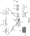
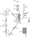
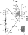
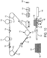
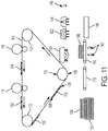
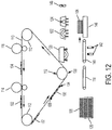
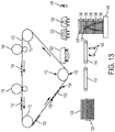
- exemplary three-dimensional (3-D) printers herein include, among other components, an intermediate transfer belt 110 (ITB) supported on rollers 112, a first printing component 116, a second printing component 114, and a platen 118 (which can be a surface or belt) adjacent the ITB 110. Further, a sheet feeder 126 maintains sheets 108 of media. Also, such structures include a heater 120 and a rinsing station 140, 142 positioned adjacent the platen 118. The rinsing station 142 includes a mesh belt 140 and jets 142. Also included is a platform 146, and a bonding station is positioned to apply light (e.g. UV light) using a light source 124 and/or heat using a heater 122. The structure can also include a support material removal station 148.
- the first printing component 116 (which can be, for example, a photoreceptor) is positioned to electrostatically transfer (by way of charge difference between the belt and the material being transferred) a first material 104 (e.g., the build material, such as a (potentially dry) powder polymer-wax material (e.g., charged 3-D toner)) to the ITB 110, and a second printing component 114 (which can also be, for example, a photoreceptor) is positioned to also electrostatically transfer a second material 105 (e.g., the support material, again such as a powder polymer-wax material (e.g., charged 3-D toner)) to a location of the ITB 110 where the first material 104 is located on the ITB 110.
- a first material 104 e.g., the build material, such as a (potentially dry) powder polymer-wax material (e.g., charged 3-D toner)
- a second printing component 114 (which
- the support material 105 dissolves in solvents that do not affect the build material 104 to allow the printed 3-D structure 104 to be separated from the support material 105 used in the printing process.
- the combination of the build material 104 and the support material 105 is shown as element 102, and is referred to as a developed layer.
- the developed layer 102 of the build material 104 and the support material 105 is on a discrete area of the ITB 110 and is in a pattern corresponding to the components of the 3-D structure in that layer (and its associated support elements), where the 3-D structure is being built, developed layer 102 by developed layer 102.
- the sheet feeder 126 is positioned to and does feed sheets 108 of media to the platen 118, using well-known, grabbers, rollers, nips, belts, etc. (all generally illustrated by item 126).
- the platen 118 is a vacuum belt further moving the sheet 108 and holding the sheet 108 is place during the subsequent processing.
- the platen 118 moves (using motors, gears, pulleys, cables, guides, etc. (all generally illustrated by item 118)) toward the ITB 110 to have the sheet of media 108 that is positioned on the platen 118 make contact with the ITB 110.
- the ITB 110 electrostatically transfers one of the developed layer 102 of the build material 104 and the support material 105 to the sheet 108 each time the platen 118 contacts the sheet 108 with the ITB 110, to successively form developed layers 102 of the build material 104 and the support material 105 on the sheet 108.
- each separate development device 114, 116 Such build and support material are printed in a pattern on the ITB by each separate development device 114, 116, and combine together in the developed layers 102 to represent a specific pattern having a predetermined length.
- each of the developed layers 102 has a leading edge 134 oriented toward the processing direction in which the ITB 110 is moving (represented by arrows next to the ITB 110) and a trailing edge 136 opposite the leading edge 134.
- the leading edge 134 of the developed layer 102 within the transfuse nip 130 begins to be transferred to a corresponding location of the platen 118.
- the platen 118 moves to contact the developed layer 102 on the ITB 110 at a location where the leading edge 134 of the developed layer 102 is at the lowest location of the roller of the transfuse nip 130.
- the trailing edge 136 of the developed layer 102 has not yet reached the transfuse nip 130 and has not, therefore, yet been transferred to the platen 118.
- the platen 118 moves synchronously with the ITB 110 (moves at the same speed and the same direction as the ITB 110) either by moving or rotating the platen vacuum belt, to allow the developed layers 102 to transfer cleanly to the platen 118, without smearing.
- the trailing edge 136 of the developed layer 102 is the only portion that has not yet reached the transfuse nip 130 and has not, therefore, been transferred to the platen 118 or partially formed part 106.
- the platen 118 moves at the same speed and in the same direction as the ITB 110, until the trailing edge 136 of the developed layer 102 reaches the bottom of the roller of the transfuse nip 130, at which point the platen 118 moves away from the ITB 110 and over to the heater 120, as shown in Figure 4 (the heater 120 can be a non-contact (e.g., infrared (IR) heater, or a pressure heater, such as a fuser roller).
- IR infrared
- the platen 118 moves synchronously as the roller rotates, heating and pressing to fuse the developed layer 102 to the sheet 108.
- This synchronous movement between the platen 118 and the ITB 110 (and heater roller 120) causes the pattern of support and build materials (102) that is printed by the development devices 116, 114 to be transferred precisely from the ITB 110 to the platen 118, without distortion or smearing.
- the platen 118 can move to the heater 120 and bonding heater/UV light 122/124 after each time the ITB 110 transfers each of the developed layers 102 to the sheet 108 to independently heat each of the developed layers 102 and successively join each the developed layer 102 to the sheet 108 and to any previously transferred developed layers 102 on the sheet 108.
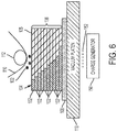
- Figure 6 is an expanded diagram showing how the developed layers 102 may contain some of the build material 104 and some of the support material 105, and how the lowest developed layer 102 is joined to the sheet 108, and how each successive developed layer 102 contacts and is joined to the immediately preceding adjacent developed layer 102 that is below (e.g., is between the layer 102 and the sheet 108) to form a stack 106 of developed layers 102 on the single sheet 108.
- the particles of build materials 104 and support material 105 within the developed layer 102 are charged particles, and Figure 6 shows these items as negatively charged particles (or they could be positively charged).
- the printing components 114, 116 provide the charge to the particles 102 in order to have such particles electrostatically transfer to the ITB 110.
- a charge generator 150 can be used to create an opposite charge 152 (in this case a positive charge) on the opposite side of the platen 118, and this opposite charge 152 draws the charged particles 102 from the ITB 110 to the top of the stack 106.
- the height of the stack 106 will make the distance between the charged (build and support) particles 102 greater than the ability of the opposite charges 152 to attract the charged particles 102 (and this height will vary, depending upon the strength of the various charges), as shown in Figure 6 .
- processing transfers the sheet 108 and the stack 106 to the rinsing station 142, as shown in Figure 9 .
- the rinsing station 142 is positioned to receive, from the platen 118, the sheet 108 having the transferred developed layers 102 thereon. As shown in Figure 10 , the rinsing station 142 applies a liquid 144 to dissolve the sheet 108 and leave a freestanding stack 106 of the developed layers 102 (shown in Figure 11 ).
- the rinsing station 142 comprises a mesh belt 140 and jets 142 positioned to spray the liquid 144 through the mesh belt 140. The liquid 144 only dissolves the sheet 108, and does not affect the build material 104 or the support material 105.
- the sheets 108 can be water-soluble, so that the liquid 144 used in Figure 10 can be water.
- the sheets 108 can be formed of any material that is dissolvable in a solvent that does not affect the build material 104 or the support material 105.
- the sheets 108 can be formed of any form a plastic, polymer, rubber, cloth, paper, etc.
- the devices and methods described herein and work with any materials for the sheets 108, build material 104, and support material 105, so long as these materials are selectively dissolvable in different solvents that do not affect the other materials.
- the platform 146 is positioned to receive, from the rinsing station 142, the freestanding stack 106.
- the bonding station 122, 124 is configured to apply light and/or heat to the 3-D structure to bond the developed layers 102 in the freestanding stack 106 to one another on the platform 146.
- the selective use of heaters, lights, and other components 122, 124 of the bonding station will vary depending upon the chemical makeup of the developed layers 102.
- the build material 104 can include UV curable toners.
- Bonding station 122, 124 bonds such materials by heating the materials to a temperature between their glass transition temperature and their melting temperature, and then applies UV light to cross-link the polymers within the materials, thereby creating a rigid structure.
- Bonding station 122, 124 bonds such materials by heating the materials to a temperature between their glass transition temperature and their melting temperature, and then applies UV light to cross-link the polymers within the materials, thereby creating a rigid structure.
- the bonding station 122, 124 applies light and/or heat after each time the rinsing station 142 transfers each of the freestanding stacks 106 to the platform 146, to independently bond the developed layers 102 in each of the freestanding stacks 106 to each other, and to any previously transferred freestanding stacks 106 of the 3-D structure on the platform 146, as shown in Figure 13 , to successively form a 3-D structure of freestanding stacks 106.
- Figure 13 illustrates an overlay showing portions of support material 105 and build material 104 within the accumulation of freestanding stacks 106. Such may or may not be visible, and is only illustrated to show one exemplary way in which such build and support materials may be arranged.
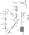
- the 3-D structure of freestanding stacks 106 can be output to allow manual removal of the support material 105 using an external solvent bath; or processing can proceed as shown in Figure 14-16 . More specifically, in Figure 14 , the support material removal station 148 is positioned to receive the now bonded 3-D structure of freestanding stacks 106 from the platform 146. The support material removal station 148 applies a solvent 156 that dissolves the support material 105 without affecting the build material 104. Again, as noted above, the solvent utilized will depend upon the chemical makeup of the build material 104 and the support material 105.
- Figure 15 illustrates the processing where about half of the support material 105 remains, and a portion of the build material 104 protrudes from the remaining stack of support material 105.
- Figure 16 illustrates processing after the support material removal station 148 has applied sufficient solvent 156 to dissolve all the support material 105, leaving only the build material 104 remaining, which leave a completed 3-D structure made of only the build material 104.
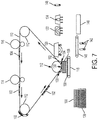
- FIGs 17 and 18 illustrate an alternative 3-D electrostatic printing structure herein which includes a planar transfuse station 138 in place of the transfuse nip 130 shown in Figure 2 .
- the planar transfuse station 138 is a planar portion of the ITB 110 that is between rollers 112 and is parallel to the platen 118.
- Figure 18 with this structure, when the platen 118 moves to contact the planar transfuse station 138, all of the developed layer 102 is transferred simultaneously to the platen 118 or partially formed stack 106, avoiding the rolling transfuses process shown in Figures 2 and 3 .
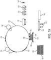
- a drum 178 could be used in place of the ITB 110, with all other components operating as described herein.
- the drum 178 could be an intermediate transfer surface receiving material from development stations 114, 116, as described above, or could be a photoreceptor and operate as the photoreceptor 256 described below operates, by maintaining a latent image of charge and receiving materials from development devices 254.
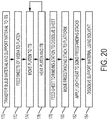
- Figure 20 is flowchart illustrating exemplary methods herein.
- various exemplary methods herein automatically electrostatically transfer first and second materials to an ITB.
- the second material is transferred on the first material (e.g., to a location of the ITB where the first material is already located on the ITB). Again, the second material dissolves in different solvents relative to solvents that dissolve the first material.
- such methods further automatically feed sheets of media to a platen using a sheet feeder. Further, in item 174, these methods automatically move the platen toward the ITB to have a sheet of media positioned on the platen contact the ITB to electrostatically transfer a layer of the first material and the second material to the sheet.
- the layer of the first material and the second material is on a discrete area of the ITB and is in a pattern.
- the methods automatically move the platen to a heater to join the layer to the sheet.
- such methods automatically repeat the process of moving the platen toward the ITB to have the sheet repeatedly contact the ITB to successively form layers of the first material and the second material on the sheet, and after each time the ITB transfers each of the layers to the sheet, these methods automatically repeat the process of the moving the platen to the heater to independently heat each of the layers and successively join each the layer to the sheet and to any previously transferred ones of the layers on the platen.
- these methods automatically feed the sheet having the layers thereon to a rinsing station, and automatically apply a liquid to dissolve the sheet and leave a freestanding stack of the layers using the rinsing station.
- the liquid only dissolves the sheet, and does not affect the first material or the second material.
- the rinsing station comprises a mesh belt and jets positioned to spray the liquid through the mesh belt.
- these methods automatically feed the freestanding stack to a platform to successively form a 3D structure of freestanding stacks of the layers.
- these methods automatically apply light and/or heat to the 3-D structure to bond the freestanding stacks to one another on the platform using a bonding station. More specifically, the bonding process in item 182 applies the light and/or heat after each time the rinsing station transfers each of the freestanding stacks to the platform to independently bond each the freestanding stack to any previously transferred ones of the freestanding stacks of the 3-D structure on the platform.
- these methods can automatically feed the 3D structure to a support material removal station and apply a solvent there that dissolves the second material without affecting the first material to leave the 3D structure made of only the second material at the support material removal station.
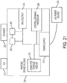
- FIG. 21 illustrates many components of 3-D printer structures 204 herein.
- the 3-D printing device 204 includes a controller/tangible processor 224 and a communications port (input/output) 214 operatively connected to the tangible processor 224 and to a computerized network external to the printing device 204.
- the printing device 204 can include at least one accessory functional component, such as a graphical user interface (GUI) assembly 212.
- GUI graphical user interface
- the user may receive messages, instructions, and menu options from, and enter instructions through, the graphical user interface or control panel 212.
- the input/output device 214 is used for communications to and from the 3-D printing device 204 and comprises a wired device or wireless device (of any form, whether currently known or developed in the future).
- the tangible processor 224 controls the various actions of the printing device 204.
- a non-transitory, tangible, computer storage medium device 210 (which can be optical, magnetic, capacitor based, etc., and is different from a transitory signal) is readable by the tangible processor 224 and stores instructions that the tangible processor 224 executes to allow the computerized device to perform its various functions, such as those described herein.
- a body housing has one or more functional components that operate on power supplied from an alternating current (AC) source 220 by the power supply 218.
- the power supply 218 can comprise a common power conversion unit, power storage element (e.g., a battery, etc), etc.
- the 3-D printing device 204 includes at least one marking device (printing engine(s)) 240 that deposits successive layers of build and support material on a platen as described above, and are operatively connected to a specialized image processor 224 (that is different than a general purpose computer because it is specialized for processing image data). Also, the printing device 204 can include at least one accessory functional component (such as a scanner 232) that also operates on the power supplied from the external power source 220 (through the power supply 218).
- a marking device printing engine(s)
- a specialized image processor 224 that is different than a general purpose computer because it is specialized for processing image data.
- the printing device 204 can include at least one accessory functional component (such as a scanner 232) that also operates on the power supplied from the external power source 220 (through the power supply 218).
- the one or more printing engines 240 are intended to illustrate any marking device that applies build and support materials (toner, etc.) whether currently known or developed in the future and can include, for example, devices that use an intermediate transfer belt 110 (as shown in Figure 22 ).
- each of the printing engine(s) 240 shown in Figure 11 can utilize one or more potentially different (e.g., different color, different material, etc.) build material development stations 116, one or more potentially different (e.g., different color, different material, etc.) support material development stations 114, etc.
- the development stations 114, 116 can be any form of development station, whether currently known or developed in the future, such as individual electrostatic marking stations, individual inkjet stations, individual dry ink stations, etc.
- Each of the development stations 114, 116 transfers a pattern of material to the same location of the intermediate transfer belt 110 in sequence during a single belt rotation (potentially independently of a condition of the intermediate transfer belt 110) thereby, reducing the number of passes the intermediate transfer belt 110 must make before a full and complete image is transferred to the intermediate transfer belt 110.
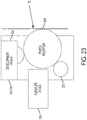
- FIG. 23 One exemplary individual electrostatic development station 114, 116 is shown in Figure 23 positioned adjacent to (or potentially in contact with) intermediate transfer belt 110.
- Each of the individual electrostatic development stations 114, 116 includes its own charging station 258 that creates a uniform charge on an internal photoreceptor 256, an internal exposure device 260 that patterns the uniform charge into a patterned charge on the photoreceptor, and an internal development device 254 that transfers build or support material to the photoreceptor 256. The pattern of build or support material is then transferred from the photoreceptor 256 to the intermediate transfer belt 110 and eventually from the intermediate transfer belt to the sheet 108.
- Figure 23 illustrates five development stations adjacent or in contact with a rotating belt (110), as would be understood by those ordinarily skilled in the art, such devices could use any number of marking stations (e.g., 2, 3, 5, 8, 11, etc.).
- an additive manufacturing system for printing a 3-D part using electrophotography includes a photoconductor component having a surface, and a development station, where the development station is configured to developed layers of a material on the surface of the photoconductor component.
- the system also includes a transfer medium configured to receive the developed layers from the surface of the rotatable photoconductor component, and a platen configured to receive the developed layers from the transfer component in a layer-by-layer manner to print the 3-D part from at least a portion of the received layers.
- UV curable toners As disclosed in US 7,250,238 it is known to provide a UV curable toner composition, as are methods of utilizing the UV curable toner compositions in printing processes.
- US 7,250,238 discloses various toner emulsion aggregation processes that permit the generation of toners that in embodiments can be cured, that is by the exposure to UV radiation, such as UV light of has about 100 nm to about 400 nm.
- the toner compositions produced can be utilized in various printing applications such as temperature sensitive packaging and the production of foil seals.
- a UV curable toner composition comprised of an optional colorant, an optional wax, a polymer generated from styrene, and acrylate selected from the group consisting of butyl acrylate, carboxyethyl acrylate, and a UV light curable acrylate oligomer. Additionally, these aspects relate to a toner composition comprised of a colorant such as a pigment, an optional wax, and a polymer generated from a UV curable cycloaliphatic epoxide.
- US 7,250,238 discloses a method of forming a UV curable toner composition
- a method of forming a UV curable toner composition comprising mixing a latex containing a polymer formed from styrene, butyl acrylate, a carboxymethyl acrylate, and a UV curable acrylate with a colorant and wax; adding flocculant to this mixture to optionally induce aggregation and form toner precursor particles dispersed in a second mixture; heating the toner precursor particles to a temperature equal to or higher than the glass transition temperature (Tg) of the polymer to form toner particles; optionally washing the toner particles; and optionally drying the toner particles.
- Tg glass transition temperature
- Computerized devices that include chip-based central processing units (CPU's), input/output devices (including graphic user interfaces (GUI), memories, comparators, tangible processors, etc.) are well-known and readily available devices produced by manufacturers such as Dell Computers, Round Rock TX, USA and Apple Computer Co., Cupertino CA, USA.
- Such computerized devices commonly include input/output devices, power supplies, tangible processors, electronic storage memories, wiring, etc., the details of which are omitted herefrom to allow the reader to focus on the salient aspects of the systems and methods described herein.
- printers, copiers, scanners and other similar peripheral equipment are available from Xerox Corporation, Norwalk, CT, USA and the details of such devices are not discussed herein for purposes of brevity and reader focus.
- printer or printing device encompasses any apparatus, such as a digital copier, bookmaking machine, facsimile machine, multifunction machine, etc., which performs a print outputting function for any purpose.
- the details of printers, printing engines, etc. are well-known and are not described in detail herein to keep this disclosure focused on the salient features presented.
- the systems and methods herein can encompass systems and methods that print in color, monochrome, or handle color or monochrome image data. All foregoing systems and methods are specifically applicable to electrostatographic and/or xerographic machines and/or processes.
- the term fixing means the drying, hardening, polymerization, crosslinking, binding, or addition reaction or other reaction of the coating.
- terms such as “right”, “left”, “vertical”, “horizontal”, “top”, “bottom”, “upper”, “lower”, “under”, “below”, “underlying”, “over”, “overlying”, “parallel”, “perpendicular”, etc., used herein are understood to be relative locations as they are oriented and illustrated in the drawings (unless otherwise indicated). Terms such as “touching”, “on”, “in direct contact”, “abutting”, “directly adjacent to”, etc., mean that at least one element physically contacts another element (without other elements separating the described elements).
- the terms automated or automatically mean that once a process is started (by a machine or a user), one or more machines perform the process without further input from any user.
- the same identification numeral identifies the same or similar item.
Claims (6)
- Imprimante tridimensionnelle (3-D) comprenant :une surface de transfert intermédiaire (110) ayant une couche d'un premier matériau (104) et d'un deuxième matériau (105), ladite couche dudit premier matériau et dudit deuxième matériau étant sur une zone discrète de ladite surface de transfert intermédiaire et étant sous la forme d'un motif ;une platine (118) se déplaçant par rapport à ladite surface de transfert intermédiaire (110) ;un chargeur de feuilles (126) positionné pour délivrer des feuilles de support (108) à ladite platine, ladite platine se déplaçant en direction de ladite surface de transfert intermédiaire pour avoir une feuille dudit support positionnée sur ladite platine en contact avec ladite surface de transfert intermédiaire (110), ladite surface de transfert intermédiaire transférant de manière électrostatique une couche dudit premier matériau (104) et dudit deuxième matériau (105) à ladite feuille (108) à chaque fois que ladite platine met en contact ladite feuille avec ladite surface de transfert intermédiaire (110) de manière à former successivement des couches dudit premier matériau et dudit deuxième matériau sur ladite feuille (108) ;un poste de rinçage (140) positionné pour recevoir, depuis ladite platine (118), ladite feuille (108) ayant lesdites couches sur celle-ci, ledit poste de rinçage appliquant un liquide pour dissoudre ladite feuille et laisser un empilement autoportant desdites couches ; etune plateforme (146) positionnée pour recevoir, depuis ledit poste de rinçage (140), ledit empilement autoportant pour former successivement une structure 3-D d'empilements autoportants desdites couches.
- Imprimante 3-D selon la revendication 1, dans laquelle ledit liquide dissout uniquement ladite feuille (108) et n'affecte pas ledit premier matériau (104) ou ledit deuxième matériau (105).
- Imprimante 3-D selon la revendication 1, dans laquelle ledit poste de rinçage (140) comprend une courroie maillée et des jets positionnés pour pulvériser ledit liquide à travers ladite courroie maillée.
- Imprimante 3-D selon la revendication 1, dans laquelle la surface de transfert intermédiaire (110) est une courroie de transfert intermédiaire (ITB) ; et
l'imprimante comprenant en outre
un premier photorécepteur (116) positionné pour transférer de manière électrostatique le premier matériau audit ITB
un deuxième photorécepteur positionné pour transférer de manière électrostatique le deuxième matériau à un emplacement de ladite ITB où ledit premier matériau est placé sur ladite ITB, ledit deuxième matériau se dissolvant dans des solvants qui n'affectent pas ledit premier matériau ;
un dispositif chauffant (122) adjacent à ladite platine (118), ladite platine se déplaçant vers ledit dispositif chauffant après chaque fois que ladite ITB transfère chacune desdites couches à ladite feuille pour chauffer indépendamment chacune desdites couches et joindre successivement chaque dite couche à ladite feuille (108) et à de quelconques couches antérieurement transférées parmi lesdites couches sur ladite platine ; et
un poste de collage positionné pour appliquer de la lumière et/ou de la chaleur à ladite structure 3-D pour coller lesdits empilements autoportants les uns aux autres sur ladite plateforme. - Procédé comprenant :le chargement automatique de feuilles de support (108) sur une platine (118) par utilisation d'un chargeur de feuilles (128) ;le déplacement automatique de ladite platine (118) en direction d'une surface de transfert intermédiaire (110) afin qu'une feuille dudit support (108) positionnée sur ladite platine soit en contact avec ladite surface de transfert intermédiaire pour le transfert électrostatique d'une couche d'un premier matériau (104) et d'un deuxième matériau (105) à ladite feuille (108), ladite couche dudit premier matériau et dudit deuxième matériau étant sur une zone discrète de ladite surface de transfert intermédiaire et étant sous la forme d'un motif ;la répétition automatique dudit déplacement de ladite platine (118) en direction de ladite surface de transfert intermédiaire (110) pour que ladite feuille soit en contact répété avec ladite surface de transfert intermédiaire pour former successivement des couches dudit premier matériau et dudit deuxième matériau sur ladite feuille (108) ;l'introduction automatique de ladite feuille (108) ayant lesdites couches sur celle-ci dans un poste de rinçage (140) ;l'application automatique d'un liquide pour dissoudre ladite feuille (108) et laisser un empilement autoportant desdites couches par utilisation dudit poste de rinçage (140) ; etl'introduction automatique dudit empilement autoportant sur une plateforme (146) pour la formation successive d'une structure 3-D d'empilements autoportants desdites couches.
- Procédé selon la revendication 5, dans lequel
la surface de transfert intermédiaire (110) est une courroie de transfert intermédiaire (ITB) ; et
le procédé comprenant en outre
le transfert électrostatique automatique d'un premier matériau à l'ITB ;
le transfert électrostatique automatique du deuxième matériau (105) à un emplacement de ladite ITB où ledit premier matériau (104) est placé sur ladite ITB, ledit deuxième matériau se dissolvant dans des solvants qui n'affectent pas ledit premier matériau ;
le déplacement automatique de ladite platine vers un dispositif chauffant (140) pour joindre ladite couche à ladite feuille ;
après chaque fois que ladite ITB transfère chacune desdites couches à ladite feuille, la répétition automatique dudit déplacement de ladite platine vers ledit dispositif chauffant pour chauffer indépendamment chacune desdites couches et joindre successivement chaque dite couche à ladite feuille et à de quelconques couches antérieurement transférées parmi lesdites couches sur ladite platine ; et
l'application automatique de lumière et/ou de chaleur à ladite structure 3-D pour coller lesdits empilements autoportants les uns aux autres sur ladite plateforme par utilisation d'un poste de collage.
Applications Claiming Priority (1)
| Application Number | Priority Date | Filing Date | Title |
|---|---|---|---|
| US15/098,655 US10046512B2 (en) | 2016-04-14 | 2016-04-14 | Electro-photographic 3-D printing using dissolvable paper |
Publications (2)
| Publication Number | Publication Date |
|---|---|
| EP3231579A1 EP3231579A1 (fr) | 2017-10-18 |
| EP3231579B1 true EP3231579B1 (fr) | 2019-08-28 |
Family
ID=58501399
Family Applications (1)
| Application Number | Title | Priority Date | Filing Date |
|---|---|---|---|
| EP17165628.3A Active EP3231579B1 (fr) | 2016-04-14 | 2017-04-07 | Impression électrophotographique 3d à l'aide de papier soluble |
Country Status (5)
| Country | Link |
|---|---|
| US (1) | US10046512B2 (fr) |
| EP (1) | EP3231579B1 (fr) |
| JP (1) | JP6757689B2 (fr) |
| KR (1) | KR102154471B1 (fr) |
| CN (1) | CN107297895B (fr) |
Families Citing this family (4)
| Publication number | Priority date | Publication date | Assignee | Title |
|---|---|---|---|---|
| US20230191698A1 (en) * | 2020-05-21 | 2023-06-22 | Tritone Technologies Ltd. | Wax base for an object in additive manufacturing |
| CN113119583B (zh) * | 2021-04-19 | 2022-07-29 | 深圳市联祥印刷有限公司 | 一种便于校准的印刷装置及其校准方法 |
| JP2024003990A (ja) * | 2022-06-28 | 2024-01-16 | 富士フイルムビジネスイノベーション株式会社 | 画像形成装置 |
| JP2024003993A (ja) * | 2022-06-28 | 2024-01-16 | 富士フイルムビジネスイノベーション株式会社 | 画像形成装置 |
Family Cites Families (29)
| Publication number | Priority date | Publication date | Assignee | Title |
|---|---|---|---|---|
| US6206672B1 (en) * | 1994-03-31 | 2001-03-27 | Edward P. Grenda | Apparatus of fabricating 3 dimensional objects by means of electrophotography, ionography or a similar process |
| US6066285A (en) * | 1997-12-12 | 2000-05-23 | University Of Florida | Solid freeform fabrication using power deposition |
| US6376148B1 (en) * | 2001-01-17 | 2002-04-23 | Nanotek Instruments, Inc. | Layer manufacturing using electrostatic imaging and lamination |
| US7250238B2 (en) | 2003-12-23 | 2007-07-31 | Xerox Corporation | Toners and processes thereof |
| US7261542B2 (en) | 2004-03-18 | 2007-08-28 | Desktop Factory, Inc. | Apparatus for three dimensional printing using image layers |
| US7270408B2 (en) | 2005-01-14 | 2007-09-18 | Xerox Corporation | Low level cure transfuse assist for printing with radiation curable ink |
| US20070241482A1 (en) * | 2006-04-06 | 2007-10-18 | Z Corporation | Production of three-dimensional objects by use of electromagnetic radiation |
| GB2446386A (en) * | 2007-02-06 | 2008-08-13 | Univ Montfort | Electrostatic printing method and its use in rapid prototyping |
| US7851549B2 (en) | 2007-12-13 | 2010-12-14 | Xerox Corporation | Curable polyester latex made by phase inversion emulsification |
| US20100140852A1 (en) | 2008-12-04 | 2010-06-10 | Objet Geometries Ltd. | Preparation of building material for solid freeform fabrication |
| RU2555281C2 (ru) * | 2008-12-22 | 2015-07-10 | Недерландсе Органисати Вор Тугепаст-Натюрветенсхаппелейк Ондерзук Тно | Способ и аппарат для послойного изготовления объемного объекта |
| EP2226683A1 (fr) * | 2009-03-06 | 2010-09-08 | Nederlandse Organisatie voor toegepast -natuurwetenschappelijk onderzoek TNO | Système d'éclairage pour une utilisation dans un appareil de stéréolithographie |
| US8470231B1 (en) | 2009-06-01 | 2013-06-25 | Stratasys Ltd. | Three-dimensional printing process for producing a self-destructible temporary structure |
| CN102612672B (zh) * | 2009-08-17 | 2015-02-25 | 惠普印迪戈股份公司 | 中间转印构件的释放层 |
| US8668859B2 (en) | 2010-08-18 | 2014-03-11 | Makerbot Industries, Llc | Automated 3D build processes |
| US8488994B2 (en) | 2011-09-23 | 2013-07-16 | Stratasys, Inc. | Electrophotography-based additive manufacturing system with transfer-medium service loops |
| US20130186558A1 (en) * | 2011-09-23 | 2013-07-25 | Stratasys, Inc. | Layer transfusion with heat capacitor belt for additive manufacturing |
| US8879957B2 (en) | 2011-09-23 | 2014-11-04 | Stratasys, Inc. | Electrophotography-based additive manufacturing system with reciprocating operation |
| US9904223B2 (en) * | 2011-09-23 | 2018-02-27 | Stratasys, Inc. | Layer transfusion with transfixing for additive manufacturing |
| CN108381909B (zh) | 2012-11-09 | 2021-05-25 | 赢创运营有限公司 | 用于挤出式3d打印法的经涂布长丝的用途和制备 |
| WO2014072147A1 (fr) | 2012-11-09 | 2014-05-15 | Evonik Industries Ag | Impression tridimensionnelle multicolore à base d'extrusion |
| US9418503B2 (en) | 2013-03-15 | 2016-08-16 | Virginia Tech Intellectual Properties, Inc. | 3D printing vending machine |
| US9481131B2 (en) | 2013-07-18 | 2016-11-01 | Mitsubishi Electric Research Laboratories, Inc. | Method and apparatus for printing 3D objects using additive manufacturing and material extruder with translational and rotational axes |
| US10369743B2 (en) | 2013-11-18 | 2019-08-06 | San Draw Inc. | Color or multi-material three-dimensional (3D) printing |
| US9744730B2 (en) | 2013-11-22 | 2017-08-29 | Stratasys, Inc. | Magnetic platen assembly for additive manufacturing system |
| JP6355063B2 (ja) * | 2013-12-18 | 2018-07-11 | 株式会社リコー | 立体形状物の製造方法、及び、立体形状物製造装置 |
| KR101767300B1 (ko) * | 2013-12-18 | 2017-08-10 | 캐논 가부시끼가이샤 | 패턴 제조 방법, 패턴 제조 장치, 구조체 제조 방법 그리고 그를 위한 제조 장치 |
| JP2015131439A (ja) * | 2014-01-14 | 2015-07-23 | コニカミノルタ株式会社 | 三次元造形装置および三次元造形方法 |
| US9403358B1 (en) * | 2015-04-17 | 2016-08-02 | Xerox Corporation | System and method for forming hydrophobic structures in a hydrophilic print medium |
-
2016
- 2016-04-14 US US15/098,655 patent/US10046512B2/en active Active
-
2017
- 2017-03-29 JP JP2017064343A patent/JP6757689B2/ja active Active
- 2017-03-29 KR KR1020170039704A patent/KR102154471B1/ko active IP Right Grant
- 2017-03-30 CN CN201710205753.XA patent/CN107297895B/zh active Active
- 2017-04-07 EP EP17165628.3A patent/EP3231579B1/fr active Active
Non-Patent Citations (1)
| Title |
|---|
| None * |
Also Published As
| Publication number | Publication date |
|---|---|
| CN107297895B (zh) | 2020-03-20 |
| JP6757689B2 (ja) | 2020-09-23 |
| JP2017189979A (ja) | 2017-10-19 |
| KR20170117874A (ko) | 2017-10-24 |
| CN107297895A (zh) | 2017-10-27 |
| US20170297266A1 (en) | 2017-10-19 |
| US10046512B2 (en) | 2018-08-14 |
| EP3231579A1 (fr) | 2017-10-18 |
| KR102154471B1 (ko) | 2020-09-10 |
Similar Documents
| Publication | Publication Date | Title |
|---|---|---|
| EP3260224B1 (fr) | Imprimante 3d électrostatique hybride faisant appel à la fusion laser | |
| EP3255504B1 (fr) | Système d'imprimante 3d électrostatique faisant appel à un matériau de nivellement et rabot mécanique | |
| US11130282B2 (en) | Electrostatic 3-D development apparatus using cold fusing | |
| EP3243659B1 (fr) | Appareil de développement 3-d électrostatique utilisant des matériaux à différents points de fusion | |
| EP3231579B1 (fr) | Impression électrophotographique 3d à l'aide de papier soluble | |
| US10086558B2 (en) | 3-D electrostatic printer using track bound platens and registration system | |
| EP3231582B1 (fr) | Impression électrophotographique 3d au moyen d'un substrat pliable | |
| US10279577B2 (en) | Electrostatic 3-D printer having rotating magnetic cores within developer rolls | |
| EP3243657B1 (fr) | Imprimante 3d électrostatique faisant appel à une réticulation par uv adressable | |
| US10201930B2 (en) | Acoustic transfude 3-D printing | |
| US10000010B2 (en) | 3-D electrostatic printer using rack and pinion registration system | |
| US10213958B2 (en) | Electrostatic 3-D printing system having acoustic transfer and corotron |
Legal Events
| Date | Code | Title | Description |
|---|---|---|---|
| PUAI | Public reference made under article 153(3) epc to a published international application that has entered the european phase |
Free format text: ORIGINAL CODE: 0009012 |
|
| STAA | Information on the status of an ep patent application or granted ep patent |
Free format text: STATUS: THE APPLICATION HAS BEEN PUBLISHED |
|
| AK | Designated contracting states |
Kind code of ref document: A1 Designated state(s): AL AT BE BG CH CY CZ DE DK EE ES FI FR GB GR HR HU IE IS IT LI LT LU LV MC MK MT NL NO PL PT RO RS SE SI SK SM TR |
|
| AX | Request for extension of the european patent |
Extension state: BA ME |
|
| STAA | Information on the status of an ep patent application or granted ep patent |
Free format text: STATUS: REQUEST FOR EXAMINATION WAS MADE |
|
| 17P | Request for examination filed |
Effective date: 20180418 |
|
| RBV | Designated contracting states (corrected) |
Designated state(s): AL AT BE BG CH CY CZ DE DK EE ES FI FR GB GR HR HU IE IS IT LI LT LU LV MC MK MT NL NO PL PT RO RS SE SI SK SM TR |
|
| GRAP | Despatch of communication of intention to grant a patent |
Free format text: ORIGINAL CODE: EPIDOSNIGR1 |
|
| STAA | Information on the status of an ep patent application or granted ep patent |
Free format text: STATUS: GRANT OF PATENT IS INTENDED |
|
| RIC1 | Information provided on ipc code assigned before grant |
Ipc: G03G 15/16 20060101ALI20190301BHEP Ipc: G03G 15/00 20060101ALI20190301BHEP Ipc: B33Y 10/00 20150101ALN20190301BHEP Ipc: B29C 64/223 20170101ALI20190301BHEP Ipc: B29C 64/141 20170101AFI20190301BHEP Ipc: G03G 15/22 20060101ALI20190301BHEP Ipc: B33Y 30/00 20150101ALN20190301BHEP |
|
| RIC1 | Information provided on ipc code assigned before grant |
Ipc: B29C 64/141 20170101AFI20190311BHEP Ipc: G03G 15/22 20060101ALI20190311BHEP Ipc: B33Y 10/00 20150101ALN20190311BHEP Ipc: B29C 64/223 20170101ALI20190311BHEP Ipc: G03G 15/16 20060101ALI20190311BHEP Ipc: B33Y 30/00 20150101ALN20190311BHEP Ipc: G03G 15/00 20060101ALI20190311BHEP |
|
| RIC1 | Information provided on ipc code assigned before grant |
Ipc: B29C 64/141 20170101AFI20190320BHEP Ipc: B33Y 10/00 20150101ALN20190320BHEP Ipc: B29C 64/223 20170101ALI20190320BHEP Ipc: B33Y 30/00 20150101ALN20190320BHEP Ipc: G03G 15/22 20060101ALI20190320BHEP Ipc: G03G 15/00 20060101ALI20190320BHEP Ipc: G03G 15/16 20060101ALI20190320BHEP |
|
| INTG | Intention to grant announced |
Effective date: 20190404 |
|
| RIC1 | Information provided on ipc code assigned before grant |
Ipc: B33Y 30/00 20150101ALN20190325BHEP Ipc: G03G 15/16 20060101ALI20190325BHEP Ipc: G03G 15/00 20060101ALI20190325BHEP Ipc: G03G 15/22 20060101ALI20190325BHEP Ipc: B29C 64/141 20170101AFI20190325BHEP Ipc: B29C 64/223 20170101ALI20190325BHEP Ipc: B33Y 10/00 20150101ALN20190325BHEP |
|
| GRAS | Grant fee paid |
Free format text: ORIGINAL CODE: EPIDOSNIGR3 |
|
| GRAA | (expected) grant |
Free format text: ORIGINAL CODE: 0009210 |
|
| STAA | Information on the status of an ep patent application or granted ep patent |
Free format text: STATUS: THE PATENT HAS BEEN GRANTED |
|
| AK | Designated contracting states |
Kind code of ref document: B1 Designated state(s): AL AT BE BG CH CY CZ DE DK EE ES FI FR GB GR HR HU IE IS IT LI LT LU LV MC MK MT NL NO PL PT RO RS SE SI SK SM TR |
|
| REG | Reference to a national code |
Ref country code: GB Ref legal event code: FG4D |
|
| REG | Reference to a national code |
Ref country code: CH Ref legal event code: EP |
|
| REG | Reference to a national code |
Ref country code: AT Ref legal event code: REF Ref document number: 1171869 Country of ref document: AT Kind code of ref document: T Effective date: 20190915 |
|
| REG | Reference to a national code |
Ref country code: IE Ref legal event code: FG4D |
|
| REG | Reference to a national code |
Ref country code: DE Ref legal event code: R096 Ref document number: 602017006435 Country of ref document: DE |
|
| REG | Reference to a national code |
Ref country code: NL Ref legal event code: MP Effective date: 20190828 |
|
| REG | Reference to a national code |
Ref country code: LT Ref legal event code: MG4D |
|
| PG25 | Lapsed in a contracting state [announced via postgrant information from national office to epo] |
Ref country code: LT Free format text: LAPSE BECAUSE OF FAILURE TO SUBMIT A TRANSLATION OF THE DESCRIPTION OR TO PAY THE FEE WITHIN THE PRESCRIBED TIME-LIMIT Effective date: 20190828 Ref country code: HR Free format text: LAPSE BECAUSE OF FAILURE TO SUBMIT A TRANSLATION OF THE DESCRIPTION OR TO PAY THE FEE WITHIN THE PRESCRIBED TIME-LIMIT Effective date: 20190828 Ref country code: PT Free format text: LAPSE BECAUSE OF FAILURE TO SUBMIT A TRANSLATION OF THE DESCRIPTION OR TO PAY THE FEE WITHIN THE PRESCRIBED TIME-LIMIT Effective date: 20191230 Ref country code: NO Free format text: LAPSE BECAUSE OF FAILURE TO SUBMIT A TRANSLATION OF THE DESCRIPTION OR TO PAY THE FEE WITHIN THE PRESCRIBED TIME-LIMIT Effective date: 20191128 Ref country code: FI Free format text: LAPSE BECAUSE OF FAILURE TO SUBMIT A TRANSLATION OF THE DESCRIPTION OR TO PAY THE FEE WITHIN THE PRESCRIBED TIME-LIMIT Effective date: 20190828 Ref country code: SE Free format text: LAPSE BECAUSE OF FAILURE TO SUBMIT A TRANSLATION OF THE DESCRIPTION OR TO PAY THE FEE WITHIN THE PRESCRIBED TIME-LIMIT Effective date: 20190828 Ref country code: BG Free format text: LAPSE BECAUSE OF FAILURE TO SUBMIT A TRANSLATION OF THE DESCRIPTION OR TO PAY THE FEE WITHIN THE PRESCRIBED TIME-LIMIT Effective date: 20191128 Ref country code: NL Free format text: LAPSE BECAUSE OF FAILURE TO SUBMIT A TRANSLATION OF THE DESCRIPTION OR TO PAY THE FEE WITHIN THE PRESCRIBED TIME-LIMIT Effective date: 20190828 |
|
| PG25 | Lapsed in a contracting state [announced via postgrant information from national office to epo] |
Ref country code: IS Free format text: LAPSE BECAUSE OF FAILURE TO SUBMIT A TRANSLATION OF THE DESCRIPTION OR TO PAY THE FEE WITHIN THE PRESCRIBED TIME-LIMIT Effective date: 20191228 Ref country code: RS Free format text: LAPSE BECAUSE OF FAILURE TO SUBMIT A TRANSLATION OF THE DESCRIPTION OR TO PAY THE FEE WITHIN THE PRESCRIBED TIME-LIMIT Effective date: 20190828 Ref country code: ES Free format text: LAPSE BECAUSE OF FAILURE TO SUBMIT A TRANSLATION OF THE DESCRIPTION OR TO PAY THE FEE WITHIN THE PRESCRIBED TIME-LIMIT Effective date: 20190828 Ref country code: AL Free format text: LAPSE BECAUSE OF FAILURE TO SUBMIT A TRANSLATION OF THE DESCRIPTION OR TO PAY THE FEE WITHIN THE PRESCRIBED TIME-LIMIT Effective date: 20190828 Ref country code: LV Free format text: LAPSE BECAUSE OF FAILURE TO SUBMIT A TRANSLATION OF THE DESCRIPTION OR TO PAY THE FEE WITHIN THE PRESCRIBED TIME-LIMIT Effective date: 20190828 Ref country code: GR Free format text: LAPSE BECAUSE OF FAILURE TO SUBMIT A TRANSLATION OF THE DESCRIPTION OR TO PAY THE FEE WITHIN THE PRESCRIBED TIME-LIMIT Effective date: 20191129 |
|
| REG | Reference to a national code |
Ref country code: AT Ref legal event code: MK05 Ref document number: 1171869 Country of ref document: AT Kind code of ref document: T Effective date: 20190828 |
|
| PG25 | Lapsed in a contracting state [announced via postgrant information from national office to epo] |
Ref country code: TR Free format text: LAPSE BECAUSE OF FAILURE TO SUBMIT A TRANSLATION OF THE DESCRIPTION OR TO PAY THE FEE WITHIN THE PRESCRIBED TIME-LIMIT Effective date: 20190828 |
|
| PG25 | Lapsed in a contracting state [announced via postgrant information from national office to epo] |
Ref country code: AT Free format text: LAPSE BECAUSE OF FAILURE TO SUBMIT A TRANSLATION OF THE DESCRIPTION OR TO PAY THE FEE WITHIN THE PRESCRIBED TIME-LIMIT Effective date: 20190828 Ref country code: PL Free format text: LAPSE BECAUSE OF FAILURE TO SUBMIT A TRANSLATION OF THE DESCRIPTION OR TO PAY THE FEE WITHIN THE PRESCRIBED TIME-LIMIT Effective date: 20190828 Ref country code: IT Free format text: LAPSE BECAUSE OF FAILURE TO SUBMIT A TRANSLATION OF THE DESCRIPTION OR TO PAY THE FEE WITHIN THE PRESCRIBED TIME-LIMIT Effective date: 20190828 Ref country code: RO Free format text: LAPSE BECAUSE OF FAILURE TO SUBMIT A TRANSLATION OF THE DESCRIPTION OR TO PAY THE FEE WITHIN THE PRESCRIBED TIME-LIMIT Effective date: 20190828 Ref country code: EE Free format text: LAPSE BECAUSE OF FAILURE TO SUBMIT A TRANSLATION OF THE DESCRIPTION OR TO PAY THE FEE WITHIN THE PRESCRIBED TIME-LIMIT Effective date: 20190828 Ref country code: DK Free format text: LAPSE BECAUSE OF FAILURE TO SUBMIT A TRANSLATION OF THE DESCRIPTION OR TO PAY THE FEE WITHIN THE PRESCRIBED TIME-LIMIT Effective date: 20190828 |
|
| PG25 | Lapsed in a contracting state [announced via postgrant information from national office to epo] |
Ref country code: IS Free format text: LAPSE BECAUSE OF FAILURE TO SUBMIT A TRANSLATION OF THE DESCRIPTION OR TO PAY THE FEE WITHIN THE PRESCRIBED TIME-LIMIT Effective date: 20200224 Ref country code: SM Free format text: LAPSE BECAUSE OF FAILURE TO SUBMIT A TRANSLATION OF THE DESCRIPTION OR TO PAY THE FEE WITHIN THE PRESCRIBED TIME-LIMIT Effective date: 20190828 Ref country code: CZ Free format text: LAPSE BECAUSE OF FAILURE TO SUBMIT A TRANSLATION OF THE DESCRIPTION OR TO PAY THE FEE WITHIN THE PRESCRIBED TIME-LIMIT Effective date: 20190828 Ref country code: SK Free format text: LAPSE BECAUSE OF FAILURE TO SUBMIT A TRANSLATION OF THE DESCRIPTION OR TO PAY THE FEE WITHIN THE PRESCRIBED TIME-LIMIT Effective date: 20190828 |
|
| REG | Reference to a national code |
Ref country code: DE Ref legal event code: R097 Ref document number: 602017006435 Country of ref document: DE |
|
| PLBE | No opposition filed within time limit |
Free format text: ORIGINAL CODE: 0009261 |
|
| STAA | Information on the status of an ep patent application or granted ep patent |
Free format text: STATUS: NO OPPOSITION FILED WITHIN TIME LIMIT |
|
| PG2D | Information on lapse in contracting state deleted |
Ref country code: IS |
|
| 26N | No opposition filed |
Effective date: 20200603 |
|
| PG25 | Lapsed in a contracting state [announced via postgrant information from national office to epo] |
Ref country code: SI Free format text: LAPSE BECAUSE OF FAILURE TO SUBMIT A TRANSLATION OF THE DESCRIPTION OR TO PAY THE FEE WITHIN THE PRESCRIBED TIME-LIMIT Effective date: 20190828 |
|
| PG25 | Lapsed in a contracting state [announced via postgrant information from national office to epo] |
Ref country code: MC Free format text: LAPSE BECAUSE OF FAILURE TO SUBMIT A TRANSLATION OF THE DESCRIPTION OR TO PAY THE FEE WITHIN THE PRESCRIBED TIME-LIMIT Effective date: 20190828 |
|
| REG | Reference to a national code |
Ref country code: CH Ref legal event code: PL |
|
| PG25 | Lapsed in a contracting state [announced via postgrant information from national office to epo] |
Ref country code: CH Free format text: LAPSE BECAUSE OF NON-PAYMENT OF DUE FEES Effective date: 20200430 Ref country code: LU Free format text: LAPSE BECAUSE OF NON-PAYMENT OF DUE FEES Effective date: 20200407 Ref country code: LI Free format text: LAPSE BECAUSE OF NON-PAYMENT OF DUE FEES Effective date: 20200430 |
|
| REG | Reference to a national code |
Ref country code: BE Ref legal event code: MM Effective date: 20200430 |
|
| PG25 | Lapsed in a contracting state [announced via postgrant information from national office to epo] |
Ref country code: BE Free format text: LAPSE BECAUSE OF NON-PAYMENT OF DUE FEES Effective date: 20200430 |
|
| PG25 | Lapsed in a contracting state [announced via postgrant information from national office to epo] |
Ref country code: IE Free format text: LAPSE BECAUSE OF NON-PAYMENT OF DUE FEES Effective date: 20200407 |
|
| PGFP | Annual fee paid to national office [announced via postgrant information from national office to epo] |
Ref country code: GB Payment date: 20220323 Year of fee payment: 6 |
|
| PG25 | Lapsed in a contracting state [announced via postgrant information from national office to epo] |
Ref country code: MT Free format text: LAPSE BECAUSE OF FAILURE TO SUBMIT A TRANSLATION OF THE DESCRIPTION OR TO PAY THE FEE WITHIN THE PRESCRIBED TIME-LIMIT Effective date: 20190828 Ref country code: CY Free format text: LAPSE BECAUSE OF FAILURE TO SUBMIT A TRANSLATION OF THE DESCRIPTION OR TO PAY THE FEE WITHIN THE PRESCRIBED TIME-LIMIT Effective date: 20190828 |
|
| PGFP | Annual fee paid to national office [announced via postgrant information from national office to epo] |
Ref country code: FR Payment date: 20220323 Year of fee payment: 6 |
|
| PG25 | Lapsed in a contracting state [announced via postgrant information from national office to epo] |
Ref country code: MK Free format text: LAPSE BECAUSE OF FAILURE TO SUBMIT A TRANSLATION OF THE DESCRIPTION OR TO PAY THE FEE WITHIN THE PRESCRIBED TIME-LIMIT Effective date: 20190828 |
|
| PGFP | Annual fee paid to national office [announced via postgrant information from national office to epo] |
Ref country code: DE Payment date: 20220322 Year of fee payment: 6 |
|
| REG | Reference to a national code |
Ref country code: DE Ref legal event code: R119 Ref document number: 602017006435 Country of ref document: DE |
|
| GBPC | Gb: european patent ceased through non-payment of renewal fee |
Effective date: 20230407 |
|
| PG25 | Lapsed in a contracting state [announced via postgrant information from national office to epo] |
Ref country code: GB Free format text: LAPSE BECAUSE OF NON-PAYMENT OF DUE FEES Effective date: 20230407 |
|
| PG25 | Lapsed in a contracting state [announced via postgrant information from national office to epo] |
Ref country code: GB Free format text: LAPSE BECAUSE OF NON-PAYMENT OF DUE FEES Effective date: 20230407 Ref country code: FR Free format text: LAPSE BECAUSE OF NON-PAYMENT OF DUE FEES Effective date: 20230430 Ref country code: DE Free format text: LAPSE BECAUSE OF NON-PAYMENT OF DUE FEES Effective date: 20231103 |