EP3230697B1 - Détecteur pour déterminer au moins un paramètre d'un milieu fluide s'écoulant dans un conduit de mesure - Google Patents
Détecteur pour déterminer au moins un paramètre d'un milieu fluide s'écoulant dans un conduit de mesure Download PDFInfo
- Publication number
- EP3230697B1 EP3230697B1 EP15775211.4A EP15775211A EP3230697B1 EP 3230697 B1 EP3230697 B1 EP 3230697B1 EP 15775211 A EP15775211 A EP 15775211A EP 3230697 B1 EP3230697 B1 EP 3230697B1
- Authority
- EP
- European Patent Office
- Prior art keywords
- sensor
- electronics compartment
- cover
- compartment cover
- measurement channel
- Prior art date
- Legal status (The legal status is an assumption and is not a legal conclusion. Google has not performed a legal analysis and makes no representation as to the accuracy of the status listed.)
- Active
Links
- 239000012530 fluid Substances 0.000 title claims description 25
- 238000005259 measurement Methods 0.000 title claims description 10
- 239000004020 conductor Substances 0.000 claims description 8
- 238000002485 combustion reaction Methods 0.000 claims description 5
- 239000000523 sample Substances 0.000 claims 1
- 239000002245 particle Substances 0.000 description 36
- 239000012528 membrane Substances 0.000 description 24
- 239000000853 adhesive Substances 0.000 description 18
- 230000001070 adhesive effect Effects 0.000 description 18
- 238000011109 contamination Methods 0.000 description 15
- 238000004026 adhesive bonding Methods 0.000 description 12
- 239000000428 dust Substances 0.000 description 11
- 230000005684 electric field Effects 0.000 description 11
- 239000000463 material Substances 0.000 description 11
- 238000000034 method Methods 0.000 description 9
- 230000008569 process Effects 0.000 description 7
- 238000009826 distribution Methods 0.000 description 6
- 238000011156 evaluation Methods 0.000 description 6
- 238000001746 injection moulding Methods 0.000 description 6
- 239000004033 plastic Substances 0.000 description 6
- 238000011144 upstream manufacturing Methods 0.000 description 6
- 239000002131 composite material Substances 0.000 description 5
- 230000013011 mating Effects 0.000 description 5
- 230000015572 biosynthetic process Effects 0.000 description 4
- 230000008859 change Effects 0.000 description 4
- 238000010438 heat treatment Methods 0.000 description 4
- 239000011159 matrix material Substances 0.000 description 4
- 229910010293 ceramic material Inorganic materials 0.000 description 3
- 239000002184 metal Substances 0.000 description 3
- 229920000049 Carbon (fiber) Polymers 0.000 description 2
- 238000009825 accumulation Methods 0.000 description 2
- 239000004917 carbon fiber Substances 0.000 description 2
- 238000013461 design Methods 0.000 description 2
- 230000000694 effects Effects 0.000 description 2
- 238000007786 electrostatic charging Methods 0.000 description 2
- 238000005516 engineering process Methods 0.000 description 2
- 239000003822 epoxy resin Substances 0.000 description 2
- 239000000835 fiber Substances 0.000 description 2
- 230000005669 field effect Effects 0.000 description 2
- 239000007788 liquid Substances 0.000 description 2
- 238000004519 manufacturing process Methods 0.000 description 2
- VNWKTOKETHGBQD-UHFFFAOYSA-N methane Chemical compound C VNWKTOKETHGBQD-UHFFFAOYSA-N 0.000 description 2
- 230000004048 modification Effects 0.000 description 2
- 238000012986 modification Methods 0.000 description 2
- 229920000647 polyepoxide Polymers 0.000 description 2
- 230000009467 reduction Effects 0.000 description 2
- 238000007789 sealing Methods 0.000 description 2
- 238000000926 separation method Methods 0.000 description 2
- 230000003068 static effect Effects 0.000 description 2
- XUIMIQQOPSSXEZ-UHFFFAOYSA-N Silicon Chemical compound [Si] XUIMIQQOPSSXEZ-UHFFFAOYSA-N 0.000 description 1
- 230000001419 dependent effect Effects 0.000 description 1
- 230000008021 deposition Effects 0.000 description 1
- 230000002349 favourable effect Effects 0.000 description 1
- 239000007789 gas Substances 0.000 description 1
- 239000003292 glue Substances 0.000 description 1
- 230000036039 immunity Effects 0.000 description 1
- 230000006872 improvement Effects 0.000 description 1
- 239000003921 oil Substances 0.000 description 1
- 238000012545 processing Methods 0.000 description 1
- 230000005855 radiation Effects 0.000 description 1
- 230000035945 sensitivity Effects 0.000 description 1
- 229910052710 silicon Inorganic materials 0.000 description 1
- 239000010703 silicon Substances 0.000 description 1
- 239000007787 solid Substances 0.000 description 1
- 239000004071 soot Substances 0.000 description 1
- 230000008719 thickening Effects 0.000 description 1
- 238000012546 transfer Methods 0.000 description 1
- XLYOFNOQVPJJNP-UHFFFAOYSA-N water Substances O XLYOFNOQVPJJNP-UHFFFAOYSA-N 0.000 description 1
Images


Classifications
-
- G—PHYSICS
- G01—MEASURING; TESTING
- G01F—MEASURING VOLUME, VOLUME FLOW, MASS FLOW OR LIQUID LEVEL; METERING BY VOLUME
- G01F1/00—Measuring the volume flow or mass flow of fluid or fluent solid material wherein the fluid passes through a meter in a continuous flow
- G01F1/68—Measuring the volume flow or mass flow of fluid or fluent solid material wherein the fluid passes through a meter in a continuous flow by using thermal effects
- G01F1/684—Structural arrangements; Mounting of elements, e.g. in relation to fluid flow
- G01F1/6842—Structural arrangements; Mounting of elements, e.g. in relation to fluid flow with means for influencing the fluid flow
-
- G—PHYSICS
- G01—MEASURING; TESTING
- G01F—MEASURING VOLUME, VOLUME FLOW, MASS FLOW OR LIQUID LEVEL; METERING BY VOLUME
- G01F1/00—Measuring the volume flow or mass flow of fluid or fluent solid material wherein the fluid passes through a meter in a continuous flow
- G01F1/68—Measuring the volume flow or mass flow of fluid or fluent solid material wherein the fluid passes through a meter in a continuous flow by using thermal effects
- G01F1/684—Structural arrangements; Mounting of elements, e.g. in relation to fluid flow
- G01F1/6845—Micromachined devices
-
- G—PHYSICS
- G01—MEASURING; TESTING
- G01F—MEASURING VOLUME, VOLUME FLOW, MASS FLOW OR LIQUID LEVEL; METERING BY VOLUME
- G01F5/00—Measuring a proportion of the volume flow
-
- G—PHYSICS
- G01—MEASURING; TESTING
- G01M—TESTING STATIC OR DYNAMIC BALANCE OF MACHINES OR STRUCTURES; TESTING OF STRUCTURES OR APPARATUS, NOT OTHERWISE PROVIDED FOR
- G01M15/00—Testing of engines
- G01M15/04—Testing internal-combustion engines
- G01M15/042—Testing internal-combustion engines by monitoring a single specific parameter not covered by groups G01M15/06 - G01M15/12
Definitions
- the flow properties can in principle be any physically and / or chemically measurable properties that qualify or quantify a flow of the fluid medium. In particular, it can be a flow velocity and / or a mass flow and / or a volume flow.
- hot-film air mass meters such as those shown in FIG Konrad Reif (Ed.): Sensors in Motor Vehicles, 1st edition 2010, pages 146-148 are described.
- Such hot-film air mass meters are generally based on a sensor chip, in particular a silicon sensor chip, with a sensor membrane as a measuring surface or sensor area over which the flowing fluid medium can flow.
- the sensor chip generally includes at least one heating element and at least two temperature sensors, which are arranged, for example, on the measuring surface of the sensor chip.
- a mass flow and / or volume flow of the fluid medium can be inferred from an asymmetry of the temperature profile detected by the temperature sensors, which is influenced by the flow of the fluid medium.
- Hot-film air mass meters are usually designed as plug-in sensors, which can be inserted permanently or exchangeably into a flow pipe.
- this flow pipe can be an intake tract of an internal combustion engine.
- a partial flow of the medium flows through at least one main channel provided in the hot-film air mass meter.
- a bypass channel is formed between the inlet and the outlet of the main channel.
- the bypass channel is designed such that it has a curved section for deflecting the partial flow of the medium that has entered through the inlet of the main channel, the curved section merging into a section in which the sensor chip is arranged.
- the last-mentioned section represents the actual measuring channel in which the sensor chip is arranged.
- a means is provided in the bypass channel which guides the flow and counteracts any separation of the flow of the partial media flow from the channel walls of the measuring channel.
- the inlet area of the main channel in the area of its opening facing the main flow direction is provided with inclined or curved surfaces, which are designed so that medium flowing into the inlet area is deflected away from the part of the main channel that leads to the sensor chip. This has the effect that liquid or solid particles contained in the medium cannot reach the sensor chip and contaminate it due to their inertia.
- a contamination of the sensor chip and in particular the micromechanical sensor membrane leads to a change in the heat balance and thus to deviations from the characteristic curve.
- Deposits on the sensor chip or the sensor carrier upstream of the micromechanical sensor membrane can also lead to a metrologically relevant thickening of the flow boundary layer. In this case, too, there may be deviations from the characteristic. Avoiding or reducing contamination is therefore a measure to achieve the lowest possible characteristic drifts over the period of use.
- the mass flow through the bypass channel is thus divided between the side facing the CMF and the side facing away from the CMF and through the gap between the end face of the sensor carrier and the bypass channel wall.
- the endeavor to precisely tailor the flow topology and to limit fluctuations in particular of the metrologically relevant catchment area upstream of the micromechanical sensor arrangement.
- a reduction in contamination, in particular in the close range and in particular in the event of contamination with relatively light dust particles that follow the flow very well, would therefore be desirable.
- the contamination of the micromechanical sensor membrane, the sensor chip and the sensor carrier is heavily dependent on the geometric and electrostatic conditions in this area.
- bypass duct cover for an air mass meter
- bypass duct cover for an air mass meter
- device housing for an air mass meter
- electronics compartment cover and sensor carrier are glued together.
- the flow-conducting channel system extends from the bypass channel inlet via a first flow path to the bypass channel outlet.
- the micromechanical measuring element is located in this path. Sufficiently light particles can follow this path. Sufficiently heavy particles leave the plug-in sensor at the rear through the main flow duct outlet.
- the "large components" bypass duct cover, device housing and electronics compartment cover form the vicinity of the micromechanical measuring element.
- the component sequence of the setting and gluing process is usually as follows. After the electronics module has been inserted into the electronics compartment of the sensor housing, when the bypass duct cover is set, an adhesive groove for the "spring” or the "adhesive blade", i.e. a narrow, circumferential side wall of the electronics module cover, is formed. The electronics module cover is therefore placed last on the sensor housing and bypass duct cover.
- the majority of the mass flow entering the plug-in sensor comes out of the plug-in sensor from the bypass duct inlet via the main flow duct outlet.
- a small part of the mass flow reaches the sensor carrier with the micromechanical measuring element via the area of the centrifugal force deflection and the mating contour with the tear-off edge.
- the bypass mass flow emerges from the plug-in sensor via the bypass duct outlet.
- the area of the sensor carrier there is both a tongue and groove system for gluing the bypass duct cover and the device housing and a tongue and groove system on the back for gluing the electronics module cover and the bypass duct cover.
- the grooves in the device housing can be filled with adhesive on the so-called adhesive value of the electronics module cover.
- Characteristic for the branching of the mass flow is the stagnation point on the wall opposite the centrifugal force deflection. Dust particles can get to the micromechanical sensor membrane with the bypass channel mass flow. In the vicinity of the sensor carrier there is a jet-shaped area of high speed. However, light particles can reach the entire width of the sensor carrier or bypass channel via recirculation areas. A Contamination of the micromechanical measuring element is therefore possible in the entire mass flow range.
- the formation of electrical fields in the vicinity of the micromechanical measuring element is particularly important for the accumulation of particles on the micromechanical sensor membrane and the sensor chip.
- the potentials prevailing there can be formulated qualitatively as negative or positive potentials. Electrostatic charging and the attainment of such potentials can be caused, for example, by friction or charged particles directly on the components shown or indirectly via the field effect of surrounding components, e.g. B. flow tube, air filter walls, adjust.
- a sensor for determining the flow rate of an intake air mass flow of an internal combustion engine flowing through a measuring duct is known, the sensor being a sensor housing, a plug-in sensor which is or can be inserted into a flow pipe, in which the measuring duct is formed, and a sensor chip arranged in the measuring duct for determining the flow of the intake air mass flow, the sensor housing having an electronics compartment for receiving a Electronics module, an electronics compartment cover for closing the electronics compartment and a measuring channel cover, wherein the electronics compartment cover has electrically conductive properties and is electrically connected to a fixed potential.
- a sensor is therefore proposed for determining at least one parameter of a fluid medium flowing through a measuring channel, which can at least largely avoid the disadvantages of known sensors and which in particular reduces or prevents dust contamination of the micromechanical sensor membrane, the sensor chip and the sensor carrier and thus a reduction of characteristic drifts, in particular over the service life, in particular due to the deposition of dust particles on the surface of the components mentioned, enables improved electromagnetic compatibility, i.e. reduced sensitivity of electrical and electronic signal processing to radiated electromagnetic interference, and improved protection against electrostatic discharges allowed in the circuit through controlled discharge of the charge.
- the sensor for determining at least one parameter of a fluid medium flowing through a measuring channel has a sensor housing, in particular a plug-in sensor that is or can be introduced into a flow pipe, in which the measuring channel is formed, and at least one sensor chip arranged in the measuring channel to determine the parameter of the fluid medium.
- the sensor housing has an electronics compartment for receiving an electronics module and an electronics compartment cover for closing the electronics compartment.
- the electronics compartment cover has at least partially electrically conductive properties and is electrically connected to a fixed potential.
- the fixed potential is preferably the sensor ground.
- the electronics compartment cover is partially attached to the measuring duct cover in a closed state and the electronics compartment cover is designed such that the electronics compartment cover covers the sensor chip in a closed state. In other words, the electronics compartment cover and the cover overlap in a closed state Sensor chip when viewed perpendicular to the electronics compartment cover or the sensor chip.
- electrically conductive properties of the electronics compartment cover are to be understood as meaning that the electronics compartment cover is designed to conduct electrical charges. This can be achieved in that electrically conductive components, such as electrical lines, are arranged on or in the electronics compartment cover.
- the electrical conductivity is preferably implemented by the material of the electronics compartment cover.
- the electronics compartment cover is made at least partially from at least one electrically conductive material. This means that the electronics compartment cover can be made from a single material or from several materials that can differ.
- the electronics compartment cover is made of metal.
- different materials are conceivable for the electronics compartment cover.
- the electronics compartment cover can be made from one-component or two-component materials. This allows the electronics compartment cover to be manufactured using an injection molding process.
- the injection molding process can be designed in such a way that different materials or components, for example conductive and non-conductive components, can be present in different areas of the electronics compartment cover.
- fiber-matrix, ball-matrix composites or other fiber composites can be injected using the one-component or two-component process.
- the conductivity of the electronics compartment cover can be sufficiently achieved, for example, by means of a plastic injection molding process in which 15% carbon fiber components are used.
- the sensor housing can have a housing body.
- the housing body can have at least one housing body bore.
- the measuring channel cover can have at least one measuring channel cover bore.
- the electronics compartment cover can have at least one pin. In a closed state, the pin can grip into the measuring channel cover bore and the housing body bore.
- the electronics compartment cover can be electrically connected to the fixed electrical potential by means of the pin.
- the electronics module can have a printed circuit board.
- the circuit board can have at least one pin.
- the electronics compartment cover can be electrically connected to the fixed electrical potential by means of the pin.
- the circuit board can have a pin.
- the electronics compartment cover can be electrically connected to the fixed electrical potential by means of the pin.
- the main flow direction is to be understood as the local flow direction of the fluid medium at the location of the sensor or the sensor arrangement, whereby, for example, local irregularities, such as turbulence, can be disregarded.
- the main flow direction can thus be understood to mean the local averaged transport direction of the flowing fluid medium.
- the main flow direction can therefore be based on the one hand on the flow direction at the location of the sensor arrangement itself or on the flow direction in the channel within the sensor housing, such as at the location of the sensor carrier or the sensor chip, whereby the two main flow directions mentioned can differ. In the context of the present invention, it is therefore always indicated to which location the main flow direction relates. Unless otherwise specified, the main flow direction relates to the location of the sensor arrangement.
- a downstream arrangement is understood to mean the arrangement of a component at a point which the fluid medium flowing in the main flow direction reaches later than a reference point.
- an upstream arrangement of a component is to be understood as an arrangement of the component at a point which the fluid medium flowing in the main flow direction reaches earlier than a reference point in terms of time.
- the sensor carrier can be designed entirely or partially as a circuit carrier, in particular as a printed circuit board or part of a circuit carrier, in particular a printed circuit board.
- the circuit carrier in particular the printed circuit board, can have an extension which forms the sensor carrier and which protrudes into the channel, for example the measuring channel of a hot-film air mass meter.
- the remaining part of the circuit carrier, in particular the printed circuit board can be accommodated, for example, in an electronics compartment, in a housing of the sensor arrangement or a plug-in sensor of the sensor arrangement.
- a circuit board is generally to be understood as an essentially plate-shaped element which can also be used as a carrier for electronic structures, such as conductor tracks, connection contacts or the like, and preferably also has one or more such structures. Basically, at least slight deviations from the plate shape come into consideration and should be included in the concept.
- the circuit board can for example be made of a plastic material and / or a ceramic material, for example an epoxy resin, in particular a fiber-reinforced epoxy resin.
- the circuit board can be configured, for example, as a circuit board with conductor tracks, in particular printed circuit tracks (printed circuit board, PCB).
- the electronics module of the sensor arrangement can be greatly simplified and, for example, a floor panel and a separate sensor carrier can be dispensed with.
- the base plate and sensor carrier can be replaced by a single printed circuit board, on which, for example, a control and evaluation circuit of the sensor arrangement can be arranged in whole or in part.
- This control and evaluation circuit of the sensor arrangement is used to control the at least one sensor chip and / or to evaluate the signals generated by this sensor chip.
- the manufacturing effort of the sensor arrangement can be reduced considerably and the space requirement for the electronics module can be greatly reduced.
- the sensor arrangement can in particular have at least one housing, the channel being formed in the housing.
- the channel can comprise a main channel and a bypass channel or measuring channel, wherein the sensor carrier and the sensor chip can be arranged, for example, in the bypass or measuring channel.
- the housing can have an electronics compartment that is separate from the bypass duct, the electronics module or the printed circuit board being essentially accommodated in the electronics compartment.
- the sensor carrier can then be designed as an extension of the printed circuit board projecting into the channel. This arrangement is comparatively easy to implement technically, in contrast to the complex electronic modules which are known from the prior art.
- the sensor carrier can at least partially be configured as a multilayer sensor carrier.
- the sensor carrier can be designed using what is known as multilayer technology and have two or more carrier layers connected to one another.
- these carrier layers can in turn be made of a metal, a plastic or a ceramic material or a composite material and can be connected by connection techniques, such as. B. gluing, be connected to each other.
- the leading edge can be at least partially stepped against the main flow direction of the fluid medium by differently dimensioning the carrier layers.
- the profiles can be implemented at least approximately in stages. For example, profiles that are rectangular in shape or — approximately by a step shape — at least approximately round, rounded or wedge-shaped profiles can be formed in a sectional plane perpendicular to the plane of extent of the sensor carrier.
- the sensor chip can be arranged on or in the sensor carrier in such a way that it is oriented perpendicular to the local main flow direction.
- the sensor chip can be configured to be rectangular, one side of this rectangle being perpendicular or essentially perpendicular, for example with a Orientation, which deviates from the vertical by no more than 10 degrees, is arranged to the local main flow direction.
- the sensor chip can be electrically contacted via at least one electrical connection.
- the sensor carrier in particular a circuit board forming the sensor carrier or an extension of this circuit board, can have one or more conductor tracks and / or contact pads that are connected to corresponding contacts on the sensor chip, for example by a bonding process.
- the electrical connection can be protected by at least one cover and separated from the fluid medium.
- This cover can in particular be designed as a so-called glob-top, for example as a plastic drop and / or adhesive drop, which covers the electrical connection, for example the bonding wires. In this way, in particular, influences on the flow caused by the electrical connection can also be reduced, since the glob-top has a smooth surface.
- the sensor chip can have at least one sensor area.
- This sensor area can be, for example, a sensor surface made of, for example, a porous, ceramic material and / or in particular a sensor membrane.
- the flowing fluid medium can flow over the sensor membrane as a measuring surface or sensor area.
- the sensor chip comprises, for example, at least one heating element and at least two temperature sensors, which are arranged, for example, on the measuring surface of the sensor chip, one temperature sensor being mounted upstream of the heating element and the other temperature sensor being mounted downstream of the heating element.
- a mass flow and / or volume flow of the fluid medium can be inferred from an asymmetry of the temperature profile detected by the temperature sensors, which is influenced by the flow of the fluid medium.
- an inflow section of the sensor carrier is to be understood as that section of the sensor carrier which is located upstream of the sensor chip.
- a basic idea of the present invention is the provision of an electrically conductive electronics compartment cover. This significantly reduces dust contamination of the micromechanical sensor membrane, the sensor chip and the sensor carrier. In particular, characteristic drifts of the sensor over the service life can thus be reduced or avoided. Furthermore, a basic idea of the present invention is the formation of a shielded space between the bottom plate of the electronics module and the electronics compartment cover, whereby the board with the evaluation circuit located within this shielded space can be better protected against external influences by radiation and the resulting immunity to interference can be increased.
- an alternative ground potential outside or above the circuit or the sensor chip can be implemented, which in the case of electrostatic discharges with connected cabling means that the discharges do not occur in an undefined manner in the circuit when the flashover voltage is exceeded, but instead the currents are diverted directly takes place on the ground potential of the sensor and so the circuit is bypassed.
- the choice of material for the electronics compartment cover and the type of contacting the sensor can be manufactured cost-effectively with little manufacturing effort.
- FIG. 1 shows a perspective view of a sensor arrangement 10 for determining a parameter of a fluid medium.
- the sensor arrangement 10 is designed as a hot film air mass meter and comprises a sensor housing 12 designed as a plug-in sensor, which can be plugged into a flow pipe, in particular an intake tract of an internal combustion engine, for example.
- the sensor housing 12 has a housing body 14, a measuring channel cover 16, an electronics compartment 18 and an electronics compartment cover 20 for closing the electronics compartment 18.
- a channel structure 22 is formed in the housing body 16 .
- the channel structure 22 has a main channel 24 which is located in a main flow outlet 26 on the underside 30 based on the illustration in FIG Figure 1 of the sensor housing 12 opens out, as well as a bypass or measuring channel 30 branching off from the main channel 24, which opens into a bypass or measuring channel outlet 32 also arranged on the underside 30 of the sensor housing 12.
- a representative amount of the fluid medium can flow through the channel structure 22 via an inlet opening 34, which in the inserted state faces a main flow direction 36 of the fluid medium at the location of the sensor housing 12.
- FIG. 2 shows an enlarged representation of an electronics module 38 of the sensor arrangement 10.
- a sensor carrier 40 protrudes into the measuring channel 30.
- a sensor chip 42 is embedded in this sensor carrier 40 in such a way that a micromechanical sensor membrane 44 formed as a sensor area of the sensor chip 42 from can flow over the fluid medium.
- the sensor carrier 40 together with the sensor chip 42, is part of the electronics module 38.
- the electronics module 38 also has a curved base plate 46 and a printed circuit board 48 with a control and evaluation circuit 50 attached to it, for example glued on.
- the sensor chip 42 is electrically connected to the control and evaluation circuit 50 via electrical connections 52, which are designed here as wire bonding.
- the electronics module 38 created in this way is introduced into the electronics compartment 18 in the housing body 14 of the sensor housing 12, for example glued in.
- the sensor carrier 40 protrudes into the channel structure 22.
- the electronics compartment 18 is then closed by the electronics compartment cover 20.
- Figure 3 shows a plan view of a further possible embodiment of the sensor 10.
- the channel structure 22 is formed in the measuring channel cover 16.
- the measuring channel outlet 32 is formed in an end face of the measuring channel cover 16.
- the measuring channel cover 16, the housing body 14, the electronics compartment cover 20 and the sensor carrier 40 are glued together.
- a close range 54 of the sensor chip 42 is defined by the measuring channel cover 16, the housing body 14 and the electronics compartment cover 20. Particularly in the area of the sensor carrier 40, a low-tolerance setting and gluing process with sealing of the measuring channel 30 can be ensured.
- a tongue and groove system 58 is provided for gluing the components of the measuring duct cover 16, housing body 14 and electronics compartment cover 20, as will be described in more detail below.
- the tongue and groove system 58 comprises an adhesive groove 60 on the housing body 14 and at least one tongue 62 or narrow, circumferential side wall on the electronics compartment cover 20, which engages in the adhesive groove 60.
- the component sequence of the setting and gluing process is as follows: After the electronics module 38 has been inserted into the housing body 14 or the electronics compartment 18, the gluing groove 60 for the spring 62 or the narrow, circumferential side wall of the electronics compartment cover 20 is formed when the measuring channel cover 16 is set . The electronics compartment cover 20 is therefore finally placed on the housing body 14 and the measuring channel cover 16.
- Figure 4 shows a top view of the measuring channel cover 16.
- the majority of the mass flow entering the sensor housing 12 passes from the inlet opening 34 via the main flow outlet out of the sensor housing 12 via the geometry shown.
- a small part of the mass flow reaches the sensor carrier 40 with the sensor chip 42 via the area of the centrifugal force deflector 56 and a mating contour 63 with tear-off edge 64.
- the mass flow exits the measuring channel 30 via the measuring channel outlet 32 of the sensor housing 12.
- several springs 62 can be seen, which can also be designed as adhesive swords 66 or can also be referred to as such.
- the springs 62 or adhesive swords 66 of the tongue and groove system 58 serve to glue the housing body 14, the measuring duct cover 16 and the electronics compartment cover 20 and extend along the duct structure 22 In the area of the sensor carrier 40, there is therefore both a tongue and groove system 58 for gluing the measuring channel cover 16 and the housing body 14 as well as a tongue and groove system 58 on the back for gluing the electronics compartment cover 20 and the measuring channel cover 16 Figure 3 ).
- Figure 5 shows an enlarged view of the housing body 14 in the area of the measuring channel cover 16 with the electronics compartment cover 20 installed and the sensor carrier 40 with the micromechanical sensor chip 42.
- the adhesive grooves 16 in the housing body 14 and adhesive 67 on the adhesive value 66 of the electronics compartment cover 20 can be seen in particular the filling of the Gluing grooves 60 with adhesive 67, which extend along the edges of the channel structure 22 and the electronics compartment cover 20.
- Figure 6 16 shows an enlarged view of a rear side of the measuring channel cover 16.
- the adhesive groove 60 in the measuring channel cover 16 can be seen.
- changes must be made for certain variants according to the invention, which are described in more detail below, so that the advantages or improvement effects discussed below can be realized .
- Figure 7 3 shows an enlarged perspective view of the housing body 14 in an unlocked state, ie without the measuring channel cover 16. Accordingly, neither the measuring channel cover 16, in which the channel structure 22 is formed, nor the electronics module 38 is provided in the electronics compartment 18.
- the adhesive grooves 60 in the housing body 14 can be seen, which serve to fasten the electronics compartment cover 20 and are located in a wall area with an opening through which the sensor carrier protrudes out of the electronics compartment 18 and into the measuring channel 30 in the assembled state.
- Figure 8 shows the representation of possible flow conditions in the channel structure 22 of the measuring channel cover 16.
- a stagnation point 68 is characteristic of the branching Opposite contour 63 with tear-off edge 64 opposite the centrifugal force deflector 56. Dust particles can move with the mass flow through the measuring channel 30 to the micromechanical Sensor membrane 44 arrive.
- In the near area 54 of the sensor carrier 40 there is a jet-shaped area 70 of high speed. Light particles can, however, reach the entire width of the sensor carrier 40 or the measuring channel 30 via recirculation areas. A contamination of the micromechanical sensor membrane 44 is therefore possible.
- Figure 9 shows a distribution of electrical potentials in the sensor 10.
- the section runs through the measuring channel 30 in the area of the sensor carrier 40.
- a potential of 0 volts on the chip surface and 100 volts on other components were set as possible boundary conditions.
- the formation of electrical fields is particularly important for the accumulation of particles on the micromechanical sensor membrane 44 and the sensor chip 42.
- These potentials can be qualitatively formulated as negative or positive potentials for the following explanations. Electrostatic charging and the attainment of such potentials can arise, for example, through friction or charged particles directly on the components shown or indirectly via the field effect of surrounding components, such as flow tubes, air filter walls and the like.
- Charged particles are attracted by opposing charges or potentials in electrical fields and repelled by the same charges or potentials. Particles released without an initial speed in an electric field move on the path of the strongest gradients.
- a positively charged particle 72 would move in the flow space, taking into account the additional inertial forces in the vicinity of the sensor carrier 40, along the strongest gradient of the electrical field to a negative potential 74 and thus to the sensor chip 42 and the micromechanical sensor membrane 44. In this way, dust particles can settle in particular on the sensor chip 42 and the micromechanical sensor membrane 44 and, among other things, lead to a characteristic curve drift.
- the remaining area of the housing body 14 and of the measuring channel cover 16 has a positive potential 76. Therefore, in the vicinity of the sensor carrier 40 or the sensor chip 42, there is an electric field 78.
- Figure 10 shows a distribution of electrical potentials in an electrically conductive measuring channel cover 16.
- the positive potential 76 of the housing body 14 and the negative potential 74 in the area of the sensor chip 42 can be seen.
- the measuring channel cover 16 could correspondingly electrically to a negative potential 74, such as the ground potential of the Sensor 10 are set.
- the gradients of the electric field 78 are significantly less pronounced than in the illustration of FIG Figure 9 .
- the exemplary trajectory 80 of the positively charged particle 72 drawn in should result in less contamination.
- the electromagnetic compatibility with respect to the electronic components of the sensor 10 is not always given with an electrically conductive measuring channel cover 16.
- FIG. 11 shows a perspective view of a sensor 10 according to a first embodiment of the present invention, which overcomes the above-mentioned disadvantages.
- the electronics compartment cover 20 thus has electrically conductive properties.
- the electronics compartment cover 20 is made of an electrically conductive material.
- the electronics compartment cover 20 is made of metal.
- different materials are conceivable for the electronics compartment cover 20.
- the electronics compartment cover 20 can be made from one-component or two-component materials.
- the electronics compartment cover 20 can be produced by means of an injection molding process.
- the injection molding process can be designed in such a way that different materials or components, for example conductive and non-conductive components, can be present in different areas of the electronics compartment cover 20.
- fiber-matrix, ball-matrix composites or other fiber composites can be injected using the one-component or two-component process.
- the conductivity of the electronics compartment cover 20 can be achieved in a sufficient form, for example by means of a plastic injection molding process in which 15% carbon fiber components are used.
- FIG 12 shows the distribution of electrical potentials in the sensor 10 according to the invention.
- a positively charged particle 72 with its trajectory 80 can be seen.
- the electronics compartment cover 20 is electrically connected to a fixed potential 82 ( Figure 11 ).
- the fixed potential 82 is preferably the sensor ground 84.
- the electronics compartment cover 20 has a negative potential 74 and is therefore negatively charged.
- a positively charged dust particle 72 is attracted far less strongly in the near area 54 of the sensor chip 42. This means that it cannot settle on the sensor chip 42 or the micromechanical sensor membrane 44.
- Negatively charged particles are on the one hand attracted by the positively charged housing body 14 and are therefore harmless with regard to contamination-induced characteristic curve drifts.
- negatively charged particles will settle on a positively charged sensor carrier 40.
- the contamination of the sensor carrier 40 only becomes relevant to the characteristic curve when considerable particle layer thicknesses form, especially upstream of the sensor chip 42 and the micromechanical sensor membrane 44, and these significantly change the flow and temperature boundary layer in the vicinity 54 of the micromechanical sensor membrane 44.
- the relatively thin boundary layer and the high flow velocities at the sensor carrier 40 counteract the formation of such a thick particle layer.
- FIG Figure 11 Taking back to Figure 11 a possible modification of the sensor 10 according to the invention is described. Furthermore is off Figure 11 an edge 86 of the electronics compartment cover 20 can be seen.
- the edge 86 faces the measuring channel cover 16.
- the edge 86 can extend to approximately the middle of the sensor chip 42.
- an embodiment is possible in which the edge 86 is pulled forward further in the direction of the channel structure 22 so that the electronics compartment cover 20 completely covers the sensor chip 42 in a closed state.
- the advancement of the edge 86 in the form of a dimension 88 is shown in FIG Figure 11 drawn.
- Further possible modifications relate to a plurality of sections 90, 92, 94 of the edge 86 with associated dimensions 96, 98, 100.
- the width of the sections 90, 92, 94 of the edge 86 can in each case depending on the respective application or location of the Sensor carrier 40 or sensor chips 42 can be changed in order to cover the sensor chip 42 with the electronics compartment cover 20.
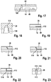
- FIG. 10 shows a perspective view of a sensor 10 according to a second embodiment of the present invention. Only the differences from the first embodiment are described below and the same components are given the same reference numerals.
- the electronics compartment cover 20 has an additional straight wall section 102 adjoining the edge 86.
- the wall sections 102 can extend parallel to a direction of longitudinal extent of the sensor housing 12.
- Figure 14 shows a perspective view of the measuring channel cover 16 of the second embodiment.
- the edge 86 has the adhesive value 66.
- the measuring channel cover 16 has a measuring channel cover bore 104. It is not shown in more detail that the housing body 14 has a housing body bore.
- Figure 15 shows a plan view of the electronics compartment cover 20 of the second embodiment.
- the electronics compartment cover 20 has at least one pin 106.
- the pin 106 is, for example, soldered to the electronics compartment cover 20 or, if it is made of plastic, is molded on. In a locked state, the pin 106 engages in the measuring channel cover bore 104 and the housing body bore.
- Figure 16 shows a bottom view of the electronics compartment cover 20 of the second embodiment. It can be seen that more than one pin 106 can also be provided. For example, two pins 106 are provided which protrude vertically from the electronics compartment cover 20 and, in a closed state, each engage in a measuring channel cover bore 104 and housing body bore. In a preferred embodiment, the electronics compartment cover 20 is electrically connected to the fixed electrical potential 82 by means of the pin 106.
- FIG. 10 shows a cross-sectional view of a sensor 10 according to a third embodiment of the present invention. Only the differences from the previous embodiments are described below and the same components are provided with the same reference symbols.
- the third embodiment represents an approximately inverse structure to the second embodiment.
- the circuit board 48 has a pin 108.
- the pin 108 can be firmly connected to the circuit board 48.
- the pin 108 is soldered to the circuit board 48.
- the electronics compartment cover 20 of the third embodiment has a conical mating contour 110.
- Figure 18 shows an enlarged section of the sensor 10 of the third embodiment.
- the pin 108 and the electronics compartment cover 20 with the conical mating contour 110 can be seen.
- the pin 108 engages in the conical mating contour 110 so that the electronics compartment cover 20 is electrically connected to the fixed electrical potential 82 by means of the pin 108.
- Figure 19 shows a section of a sensor 10 according to a fourth embodiment of the present invention. Only the differences from the previous embodiments are described below and the same components are provided with the same reference symbols.
- the circuit board 48 has a pin 112.
- the pin 112 can, for example, be an additional conductor comb pin.
- the pin 112 can be injected into the housing body 14 and extend parallel to the circuit board 48.
- the electronics compartment cover 20 is electrically connected to the fixed electrical potential 82 by means of the pin 112.
- Figure 20 shows a section of a sensor 10 according to a fifth embodiment of the present invention. Only the differences from the previous embodiments are described below and the same components are provided with the same reference symbols.
- the sensor 10 of the fifth embodiment is based on the sensor 10 of the fourth Embodiment.
- the pin 112 is not arranged parallel to the circuit board 48, but rather is bent in the direction of the electronics compartment cover 20 and away from the housing body 14.
- Figure 21 shows a section of a sensor 10 according to a sixth embodiment of the present invention. Only the differences from the previous embodiments are described below and the same components are provided with the same reference symbols.
- the sensor 10 of the sixth embodiment is based on the sensor 10 of the fifth embodiment.
- the pin 112 is bent with a radius 114 in the direction of the electronics compartment cover 20. Furthermore, the pin 112 is bent and forms contact with the electronics compartment cover 20 under pretension.
- Figure 22 shows a section of a sensor 10 according to a seventh embodiment of the present invention. Only the differences from the previous embodiments are described below and the same components are provided with the same reference symbols.
- the sensor 10 of the seventh embodiment is based on the sensor 10 of the sixth embodiment.
- the pin 112 is bent at an angle of essentially 90 °, that is to say with a deviation of no more than 10 ° from an ideal right angle, in the direction of the electronics compartment cover 20.
- FIG Figure 23 shows an enlarged section of the sensor 10 of the seventh embodiment, as shown in FIG Figure 22 is shown.
- the electronics compartment cover 20 has a conical recess 116.
- the pin 112 engages in the recess 116 and is connected to the electronics compartment cover 20 in such a way that a caulking 118 is formed with the electronics compartment cover 20.
- Figure 24 shows a cross-sectional view of a sensor 10 according to one of the previously described embodiments.
- the section runs through the electronics compartment 18.
- the printed circuit board 48 with the control and / or evaluation circuit 50 can be seen. It can also be seen how the base plate 46 clings to the housing body 14.
- the electronics compartment 18 is closed by the electronics compartment cover 20. This creates a shielded electronics compartment 18.
- Figure 25 shows a longitudinal sectional view of a sensor 10 according to one of the previously described embodiments.
- the section runs through the electronics compartment 18.
- the circuit board 48 in the electronics compartment 18 and the electrical contacting of the circuit board 48 with a plug 120 of the sensor housing 12 by means of bonding wires 122 can be seen.
- the housing body 14, the base plate 46, the electronics compartment cover 20, the The printed circuit board 48 with its electronic components, the plug 120 and the contacting of the electronics compartment cover 20 form a shielding space that is favorable with regard to electromagnetic compatibility and electrostatic discharges.
Claims (7)
- Capteur (10) pour déterminer au moins un paramètre d'un milieu fluide qui s'écoule à travers un canal de mesure (30), notamment un débit massique d'air d'aspiration d'un moteur à combustion interne, le capteur (10) possédant un boîtier de capteur (12), notamment une sonde à enficher introduite ou introductible dans un tube d'écoulement, dans lequel est formé le canal de mesure (30), et au moins une puce de capteur (42) disposée dans le canal de mesure (30) pour déterminer le paramètre du milieu fluide, le boîtier de capteur (12) possédant un espace électronique (18) destiné à accueillir un module électronique (38), un couvercle d'espace électronique (20) destiné à fermer l'espace électronique (18) et un couvercle de canal de mesure (16),
le couvercle d'espace électronique (20) possédant des propriétés de conduction électrique au moins partielle et étant relié électriquement à un potentiel fixe (82), caractérisé en ce que le couvercle d'espace électronique (20), dans un état fermé, est placé partiellement sur le couvercle de canal de mesure (16) et le couvercle d'espace électronique (20) est configuré de telle sorte que le couvercle d'espace électronique (20), dans un état fermé, recouvre la puce de capteur (42). - Capteur (10) selon la revendication précédente, le couvercle d'espace électronique (20) étant au moins partiellement fabriqué dans au moins un matériau électriquement conducteur.
- Capteur (10) selon la revendication précédente, le potentiel fixe (82) étant la masse de capteur (84).
- Capteur (10) selon la revendication 1, le boîtier de capteur (12) possédant un corps de boîtier (14), le corps de boîtier (14) possédant au moins un trou de corps de boîtier, le couvercle de canal de mesure (16) possédant au moins un trou de couvercle de canal de mesure (104), le couvercle d'espace électronique (20) possédant au moins un tenon (106), dans un état fermé, le tenon (106) pénétrant dans le trou de couvercle de canal de mesure (104) et le trou de corps de boîtier.
- Capteur (10) selon la revendication précédente, le couvercle d'espace électronique (20) étant relié électriquement au potentiel électrique fixe (82) au moyen du tenon (106).
- Capteur (10) selon l'une des revendications 1 et 3, le module électronique (38) possédant un circuit imprimé (48), le circuit imprimé (48) possédant au moins une broche (108), le couvercle d'espace électronique (20) étant relié électriquement au potentiel électrique fixe (82) au moyen de la broche (108).
- Capteur (10) selon l'une des revendications 1 et 3, le module électronique (38) possédant un circuit imprimé (48), le circuit imprimé (48) possédant au moins une patte (112), le couvercle d'espace électronique (20) étant relié électriquement au potentiel électrique fixe (82) au moyen de la patte (112).
Applications Claiming Priority (2)
| Application Number | Priority Date | Filing Date | Title |
|---|---|---|---|
| DE102014225303.9A DE102014225303A1 (de) | 2014-12-09 | 2014-12-09 | Sensor zur Bestimmung wenigstens eines Parameters eines durch einen Messkanal strömenden fluiden Mediums |
| PCT/EP2015/073045 WO2016091416A1 (fr) | 2014-12-09 | 2015-10-06 | Détecteur pour déterminer au moins un paramètre d'un milieu fluide s'écoulant dans un conduit de mesure |
Publications (2)
| Publication Number | Publication Date |
|---|---|
| EP3230697A1 EP3230697A1 (fr) | 2017-10-18 |
| EP3230697B1 true EP3230697B1 (fr) | 2020-09-23 |
Family
ID=54252310
Family Applications (1)
| Application Number | Title | Priority Date | Filing Date |
|---|---|---|---|
| EP15775211.4A Active EP3230697B1 (fr) | 2014-12-09 | 2015-10-06 | Détecteur pour déterminer au moins un paramètre d'un milieu fluide s'écoulant dans un conduit de mesure |
Country Status (5)
| Country | Link |
|---|---|
| US (1) | US10809108B2 (fr) |
| EP (1) | EP3230697B1 (fr) |
| CN (1) | CN107209037B (fr) |
| DE (1) | DE102014225303A1 (fr) |
| WO (1) | WO2016091416A1 (fr) |
Families Citing this family (11)
| Publication number | Priority date | Publication date | Assignee | Title |
|---|---|---|---|---|
| DE102014218591A1 (de) * | 2014-09-16 | 2016-03-17 | Robert Bosch Gmbh | Sensoranordnung zur Bestimmung wenigstens eines Parameters eines durch eine Kanalstruktur strömenden fluiden Mediums |
| US10760934B2 (en) * | 2014-12-05 | 2020-09-01 | Natural Gas Solutions North America, Llc | Using localized flow characteristics on electronic flow meter to quantify volumetric flow |
| US10641630B2 (en) * | 2015-09-30 | 2020-05-05 | Hitachi Automotive Systems, Ltd. | Physical quantity detection device |
| DE102016209150A1 (de) * | 2016-05-25 | 2017-11-30 | Robert Bosch Gmbh | Sensor zur Bestimmung wenigstens eines Parameters eines durch einen Messkanal strömenden fluiden Mediums |
| JP6744501B2 (ja) * | 2017-09-29 | 2020-08-19 | 日立オートモティブシステムズ株式会社 | 物理量検出装置 |
| DE102017218893A1 (de) * | 2017-10-23 | 2019-04-25 | Robert Bosch Gmbh | Sensoranordnung zur Bestimmung wenigstens eines Parameters eines durch einen Messkanal strömenden fluiden Mediums |
| JP6973268B2 (ja) | 2018-04-24 | 2021-11-24 | 株式会社デンソー | 物理量計測装置 |
| DE102018215714A1 (de) * | 2018-09-14 | 2020-03-19 | Robert Bosch Gmbh | Sensor zur Bestimmung wenigstens eines Parameters eines durch einen Messkanal strömenden fluiden Mediums |
| DE102018221847A1 (de) * | 2018-12-14 | 2020-06-18 | Robert Bosch Gmbh | Elektrische Vorrichtung mit einem Sensor |
| JP7062135B2 (ja) * | 2019-03-29 | 2022-05-02 | 日立Astemo株式会社 | 物理量検出装置 |
| WO2022123841A1 (fr) * | 2020-12-11 | 2022-06-16 | 日立Astemo株式会社 | Dispositif de détection de débit |
Family Cites Families (9)
| Publication number | Priority date | Publication date | Assignee | Title |
|---|---|---|---|---|
| DE4447570C2 (de) * | 1994-07-22 | 1999-06-02 | Bosch Gmbh Robert | Vorrichtung zur Messung der Masse eines strömenden Mediums |
| DE19815656A1 (de) * | 1998-04-08 | 1999-10-14 | Bosch Gmbh Robert | Meßvorrichtung zum Messen der Masse eines strömenden Mediums |
| DE19847303B4 (de) * | 1998-10-14 | 2006-11-30 | Robert Bosch Gmbh | Sensorelement mit antiadhäsiver Oberflächenbeschichtung |
| DE102010043062A1 (de) * | 2010-10-28 | 2012-05-03 | Robert Bosch Gmbh | Sensorvorrichtung zur Erfassung einer Strömungseigenschaft eines fluiden Mediums |
| DE102010043083A1 (de) | 2010-10-28 | 2012-05-03 | Robert Bosch Gmbh | Sensorvorrichtung zur Erfassung einer Strömungseigenschaft eines fluiden Mediums |
| DE102011078004A1 (de) * | 2011-06-22 | 2012-12-27 | Robert Bosch Gmbh | Sensoranordnung zur Bestimmung wenigstens einer Strömungseigenschaft eines mit einer Hauptströmungsrichtung strömenden fluiden Mediums |
| DE102012200121A1 (de) * | 2012-01-05 | 2013-07-11 | Robert Bosch Gmbh | Vorrichtung zur Erfassung mindestens einer Strömungseigenschaft eines fluiden Mediums |
| JP5558599B1 (ja) * | 2013-02-13 | 2014-07-23 | 三菱電機株式会社 | 熱式空気流量計 |
| DE102013215522A1 (de) * | 2013-08-07 | 2015-02-12 | Robert Bosch Gmbh | Sensorvorrichtung zur Bestimmung wenigstens eines Parameters eines durch einen Kanal strömenden fluiden Mediums |
-
2014
- 2014-12-09 DE DE102014225303.9A patent/DE102014225303A1/de not_active Withdrawn
-
2015
- 2015-10-06 US US15/533,085 patent/US10809108B2/en active Active
- 2015-10-06 CN CN201580075791.7A patent/CN107209037B/zh active Active
- 2015-10-06 EP EP15775211.4A patent/EP3230697B1/fr active Active
- 2015-10-06 WO PCT/EP2015/073045 patent/WO2016091416A1/fr active Application Filing
Non-Patent Citations (1)
| Title |
|---|
| None * |
Also Published As
| Publication number | Publication date |
|---|---|
| EP3230697A1 (fr) | 2017-10-18 |
| US20170328753A1 (en) | 2017-11-16 |
| US10809108B2 (en) | 2020-10-20 |
| DE102014225303A1 (de) | 2016-06-09 |
| WO2016091416A1 (fr) | 2016-06-16 |
| CN107209037B (zh) | 2022-11-25 |
| CN107209037A (zh) | 2017-09-26 |
Similar Documents
| Publication | Publication Date | Title |
|---|---|---|
| EP3230697B1 (fr) | Détecteur pour déterminer au moins un paramètre d'un milieu fluide s'écoulant dans un conduit de mesure | |
| EP2577237B1 (fr) | Débitmètre d'air massique | |
| DE102011078004A1 (de) | Sensoranordnung zur Bestimmung wenigstens einer Strömungseigenschaft eines mit einer Hauptströmungsrichtung strömenden fluiden Mediums | |
| DE112012005695B4 (de) | Thermischer Durchflussmesser | |
| EP3097388B1 (fr) | Système de détection servant à déterminer au moins un paramètre d'un milieu fluide circulant dans une structure de conduit | |
| EP3191804B1 (fr) | Dispositif de détection pour déterminer au moins un paramètre d'un milieu fluide s'écoulant dans un conduit de mesure | |
| DE102007024865A1 (de) | Vorrichtung zur Bestimmung wenigstens eines Parameters eines fluiden Mediums | |
| DE102008041145A1 (de) | Sensoranordnung zur Bestimmung eines Parameters eines fluiden Mediums | |
| DE102010028388B4 (de) | Luftstrommessvorrichtung | |
| EP2142890B1 (fr) | Dispositif de mesure de fluides en écoulement | |
| EP3108213B1 (fr) | Disposition de capteur pour la détermination d'au moins un paramètre d'un fluide circulant dans un canal | |
| DE102016209150A1 (de) | Sensor zur Bestimmung wenigstens eines Parameters eines durch einen Messkanal strömenden fluiden Mediums | |
| DE19735891A1 (de) | Meßvorrichtung zum Messen der Masse eines in einer Leitung strömenden Mediums | |
| EP3283853B1 (fr) | Capteur pour déterminer au moins un paramètre d'un milieu fluide s'écoulant dans un conduit de mesure | |
| DE102013226345A1 (de) | Sensoranordnung zur Bestimmung wenigstens eines Parameters eines durch einen Kanal strömenden fluiden Mediums | |
| DE102008042153A1 (de) | Sensoranordnung zur Bestimmung eines Parameters eines fluiden Mediums | |
| DE102019220425A1 (de) | Sensor zur Bestimmung wenigstens eines Parameters eines durch einen Messkanal strömenden fluiden Mediums | |
| EP3283854B1 (fr) | Capteur pour déterminer au moins un paramètre d'un milieu fluide s'écoulant dans un conduit de mesure | |
| DE102008042164B4 (de) | Vorrichtung zur Bestimmung eines Parameters eines strömenden Mediums | |
| DE112020001927T5 (de) | Durchflussmessvorrichtung | |
| DE102014215209A1 (de) | Sensor zur Bestimmung wenigstens eines Parameters eines durch einen Messkanal strömenden fluiden Mediums | |
| DE102014218579A1 (de) | Sensoranordnung zur Bestimmung wenigstens eines Parameters eines durch einen Kanal strömenden fluiden Mediums | |
| DE102015206702A1 (de) | Sensor zur Bestimmung wenigstens eines Parameters eines durch einen Kanal strömenden fluiden Mediums | |
| DE102013221791A1 (de) | Sensoranordnung zur Bestimmung wenigstens eines Parameters eines durch einen Kanal strömenden fluiden Mediums | |
| DE102011078992A1 (de) | Sensoranordnung zur Bestimmung wenigstens einer Strömungseigenschaft eines mit einer Hauptströmungsrichtung strömenden fluiden Mediums |
Legal Events
| Date | Code | Title | Description |
|---|---|---|---|
| STAA | Information on the status of an ep patent application or granted ep patent |
Free format text: STATUS: THE INTERNATIONAL PUBLICATION HAS BEEN MADE |
|
| PUAI | Public reference made under article 153(3) epc to a published international application that has entered the european phase |
Free format text: ORIGINAL CODE: 0009012 |
|
| STAA | Information on the status of an ep patent application or granted ep patent |
Free format text: STATUS: REQUEST FOR EXAMINATION WAS MADE |
|
| 17P | Request for examination filed |
Effective date: 20170710 |
|
| AK | Designated contracting states |
Kind code of ref document: A1 Designated state(s): AL AT BE BG CH CY CZ DE DK EE ES FI FR GB GR HR HU IE IS IT LI LT LU LV MC MK MT NL NO PL PT RO RS SE SI SK SM TR |
|
| AX | Request for extension of the european patent |
Extension state: BA ME |
|
| DAV | Request for validation of the european patent (deleted) | ||
| DAX | Request for extension of the european patent (deleted) | ||
| STAA | Information on the status of an ep patent application or granted ep patent |
Free format text: STATUS: EXAMINATION IS IN PROGRESS |
|
| 17Q | First examination report despatched |
Effective date: 20200103 |
|
| RAP1 | Party data changed (applicant data changed or rights of an application transferred) |
Owner name: ROBERT BOSCH GMBH |
|
| GRAP | Despatch of communication of intention to grant a patent |
Free format text: ORIGINAL CODE: EPIDOSNIGR1 |
|
| STAA | Information on the status of an ep patent application or granted ep patent |
Free format text: STATUS: GRANT OF PATENT IS INTENDED |
|
| INTG | Intention to grant announced |
Effective date: 20200626 |
|
| GRAS | Grant fee paid |
Free format text: ORIGINAL CODE: EPIDOSNIGR3 |
|
| GRAA | (expected) grant |
Free format text: ORIGINAL CODE: 0009210 |
|
| STAA | Information on the status of an ep patent application or granted ep patent |
Free format text: STATUS: THE PATENT HAS BEEN GRANTED |
|
| AK | Designated contracting states |
Kind code of ref document: B1 Designated state(s): AL AT BE BG CH CY CZ DE DK EE ES FI FR GB GR HR HU IE IS IT LI LT LU LV MC MK MT NL NO PL PT RO RS SE SI SK SM TR |
|
| REG | Reference to a national code |
Ref country code: GB Ref legal event code: FG4D Free format text: NOT ENGLISH |
|
| REG | Reference to a national code |
Ref country code: CH Ref legal event code: EP |
|
| REG | Reference to a national code |
Ref country code: DE Ref legal event code: R096 Ref document number: 502015013520 Country of ref document: DE |
|
| REG | Reference to a national code |
Ref country code: IE Ref legal event code: FG4D Free format text: LANGUAGE OF EP DOCUMENT: GERMAN |
|
| REG | Reference to a national code |
Ref country code: AT Ref legal event code: REF Ref document number: 1316863 Country of ref document: AT Kind code of ref document: T Effective date: 20201015 |
|
| PG25 | Lapsed in a contracting state [announced via postgrant information from national office to epo] |
Ref country code: GR Free format text: LAPSE BECAUSE OF FAILURE TO SUBMIT A TRANSLATION OF THE DESCRIPTION OR TO PAY THE FEE WITHIN THE PRESCRIBED TIME-LIMIT Effective date: 20201224 Ref country code: HR Free format text: LAPSE BECAUSE OF FAILURE TO SUBMIT A TRANSLATION OF THE DESCRIPTION OR TO PAY THE FEE WITHIN THE PRESCRIBED TIME-LIMIT Effective date: 20200923 Ref country code: NO Free format text: LAPSE BECAUSE OF FAILURE TO SUBMIT A TRANSLATION OF THE DESCRIPTION OR TO PAY THE FEE WITHIN THE PRESCRIBED TIME-LIMIT Effective date: 20201223 Ref country code: BG Free format text: LAPSE BECAUSE OF FAILURE TO SUBMIT A TRANSLATION OF THE DESCRIPTION OR TO PAY THE FEE WITHIN THE PRESCRIBED TIME-LIMIT Effective date: 20201223 Ref country code: FI Free format text: LAPSE BECAUSE OF FAILURE TO SUBMIT A TRANSLATION OF THE DESCRIPTION OR TO PAY THE FEE WITHIN THE PRESCRIBED TIME-LIMIT Effective date: 20200923 Ref country code: SE Free format text: LAPSE BECAUSE OF FAILURE TO SUBMIT A TRANSLATION OF THE DESCRIPTION OR TO PAY THE FEE WITHIN THE PRESCRIBED TIME-LIMIT Effective date: 20200923 |
|
| PG25 | Lapsed in a contracting state [announced via postgrant information from national office to epo] |
Ref country code: LV Free format text: LAPSE BECAUSE OF FAILURE TO SUBMIT A TRANSLATION OF THE DESCRIPTION OR TO PAY THE FEE WITHIN THE PRESCRIBED TIME-LIMIT Effective date: 20200923 Ref country code: RS Free format text: LAPSE BECAUSE OF FAILURE TO SUBMIT A TRANSLATION OF THE DESCRIPTION OR TO PAY THE FEE WITHIN THE PRESCRIBED TIME-LIMIT Effective date: 20200923 |
|
| REG | Reference to a national code |
Ref country code: NL Ref legal event code: MP Effective date: 20200923 |
|
| REG | Reference to a national code |
Ref country code: LT Ref legal event code: MG4D |
|
| PG25 | Lapsed in a contracting state [announced via postgrant information from national office to epo] |
Ref country code: CZ Free format text: LAPSE BECAUSE OF FAILURE TO SUBMIT A TRANSLATION OF THE DESCRIPTION OR TO PAY THE FEE WITHIN THE PRESCRIBED TIME-LIMIT Effective date: 20200923 Ref country code: RO Free format text: LAPSE BECAUSE OF FAILURE TO SUBMIT A TRANSLATION OF THE DESCRIPTION OR TO PAY THE FEE WITHIN THE PRESCRIBED TIME-LIMIT Effective date: 20200923 Ref country code: PT Free format text: LAPSE BECAUSE OF FAILURE TO SUBMIT A TRANSLATION OF THE DESCRIPTION OR TO PAY THE FEE WITHIN THE PRESCRIBED TIME-LIMIT Effective date: 20210125 Ref country code: SM Free format text: LAPSE BECAUSE OF FAILURE TO SUBMIT A TRANSLATION OF THE DESCRIPTION OR TO PAY THE FEE WITHIN THE PRESCRIBED TIME-LIMIT Effective date: 20200923 Ref country code: EE Free format text: LAPSE BECAUSE OF FAILURE TO SUBMIT A TRANSLATION OF THE DESCRIPTION OR TO PAY THE FEE WITHIN THE PRESCRIBED TIME-LIMIT Effective date: 20200923 Ref country code: LT Free format text: LAPSE BECAUSE OF FAILURE TO SUBMIT A TRANSLATION OF THE DESCRIPTION OR TO PAY THE FEE WITHIN THE PRESCRIBED TIME-LIMIT Effective date: 20200923 |
|
| PG25 | Lapsed in a contracting state [announced via postgrant information from national office to epo] |
Ref country code: ES Free format text: LAPSE BECAUSE OF FAILURE TO SUBMIT A TRANSLATION OF THE DESCRIPTION OR TO PAY THE FEE WITHIN THE PRESCRIBED TIME-LIMIT Effective date: 20200923 Ref country code: AL Free format text: LAPSE BECAUSE OF FAILURE TO SUBMIT A TRANSLATION OF THE DESCRIPTION OR TO PAY THE FEE WITHIN THE PRESCRIBED TIME-LIMIT Effective date: 20200923 Ref country code: PL Free format text: LAPSE BECAUSE OF FAILURE TO SUBMIT A TRANSLATION OF THE DESCRIPTION OR TO PAY THE FEE WITHIN THE PRESCRIBED TIME-LIMIT Effective date: 20200923 Ref country code: IS Free format text: LAPSE BECAUSE OF FAILURE TO SUBMIT A TRANSLATION OF THE DESCRIPTION OR TO PAY THE FEE WITHIN THE PRESCRIBED TIME-LIMIT Effective date: 20210123 |
|
| REG | Reference to a national code |
Ref country code: CH Ref legal event code: PL |
|
| REG | Reference to a national code |
Ref country code: DE Ref legal event code: R097 Ref document number: 502015013520 Country of ref document: DE |
|
| PG25 | Lapsed in a contracting state [announced via postgrant information from national office to epo] |
Ref country code: LU Free format text: LAPSE BECAUSE OF NON-PAYMENT OF DUE FEES Effective date: 20201006 Ref country code: MC Free format text: LAPSE BECAUSE OF FAILURE TO SUBMIT A TRANSLATION OF THE DESCRIPTION OR TO PAY THE FEE WITHIN THE PRESCRIBED TIME-LIMIT Effective date: 20200923 Ref country code: SK Free format text: LAPSE BECAUSE OF FAILURE TO SUBMIT A TRANSLATION OF THE DESCRIPTION OR TO PAY THE FEE WITHIN THE PRESCRIBED TIME-LIMIT Effective date: 20200923 |
|
| REG | Reference to a national code |
Ref country code: BE Ref legal event code: MM Effective date: 20201031 |
|
| PLBE | No opposition filed within time limit |
Free format text: ORIGINAL CODE: 0009261 |
|
| STAA | Information on the status of an ep patent application or granted ep patent |
Free format text: STATUS: NO OPPOSITION FILED WITHIN TIME LIMIT |
|
| PG25 | Lapsed in a contracting state [announced via postgrant information from national office to epo] |
Ref country code: LI Free format text: LAPSE BECAUSE OF NON-PAYMENT OF DUE FEES Effective date: 20201031 Ref country code: SI Free format text: LAPSE BECAUSE OF FAILURE TO SUBMIT A TRANSLATION OF THE DESCRIPTION OR TO PAY THE FEE WITHIN THE PRESCRIBED TIME-LIMIT Effective date: 20200923 Ref country code: DK Free format text: LAPSE BECAUSE OF FAILURE TO SUBMIT A TRANSLATION OF THE DESCRIPTION OR TO PAY THE FEE WITHIN THE PRESCRIBED TIME-LIMIT Effective date: 20200923 Ref country code: BE Free format text: LAPSE BECAUSE OF NON-PAYMENT OF DUE FEES Effective date: 20201031 Ref country code: CH Free format text: LAPSE BECAUSE OF NON-PAYMENT OF DUE FEES Effective date: 20201031 |
|
| 26N | No opposition filed |
Effective date: 20210624 |
|
| PG25 | Lapsed in a contracting state [announced via postgrant information from national office to epo] |
Ref country code: IT Free format text: LAPSE BECAUSE OF FAILURE TO SUBMIT A TRANSLATION OF THE DESCRIPTION OR TO PAY THE FEE WITHIN THE PRESCRIBED TIME-LIMIT Effective date: 20200923 Ref country code: IE Free format text: LAPSE BECAUSE OF NON-PAYMENT OF DUE FEES Effective date: 20201006 |
|
| REG | Reference to a national code |
Ref country code: AT Ref legal event code: MM01 Ref document number: 1316863 Country of ref document: AT Kind code of ref document: T Effective date: 20201006 |
|
| PG25 | Lapsed in a contracting state [announced via postgrant information from national office to epo] |
Ref country code: AT Free format text: LAPSE BECAUSE OF NON-PAYMENT OF DUE FEES Effective date: 20201006 |
|
| PG25 | Lapsed in a contracting state [announced via postgrant information from national office to epo] |
Ref country code: TR Free format text: LAPSE BECAUSE OF FAILURE TO SUBMIT A TRANSLATION OF THE DESCRIPTION OR TO PAY THE FEE WITHIN THE PRESCRIBED TIME-LIMIT Effective date: 20200923 Ref country code: MT Free format text: LAPSE BECAUSE OF FAILURE TO SUBMIT A TRANSLATION OF THE DESCRIPTION OR TO PAY THE FEE WITHIN THE PRESCRIBED TIME-LIMIT Effective date: 20200923 Ref country code: CY Free format text: LAPSE BECAUSE OF FAILURE TO SUBMIT A TRANSLATION OF THE DESCRIPTION OR TO PAY THE FEE WITHIN THE PRESCRIBED TIME-LIMIT Effective date: 20200923 |
|
| PG25 | Lapsed in a contracting state [announced via postgrant information from national office to epo] |
Ref country code: MK Free format text: LAPSE BECAUSE OF FAILURE TO SUBMIT A TRANSLATION OF THE DESCRIPTION OR TO PAY THE FEE WITHIN THE PRESCRIBED TIME-LIMIT Effective date: 20200923 |
|
| PG25 | Lapsed in a contracting state [announced via postgrant information from national office to epo] |
Ref country code: NL Free format text: LAPSE BECAUSE OF NON-PAYMENT OF DUE FEES Effective date: 20200923 |
|
| PGFP | Annual fee paid to national office [announced via postgrant information from national office to epo] |
Ref country code: GB Payment date: 20231025 Year of fee payment: 9 |
|
| PGFP | Annual fee paid to national office [announced via postgrant information from national office to epo] |
Ref country code: FR Payment date: 20231023 Year of fee payment: 9 |
|
| PGFP | Annual fee paid to national office [announced via postgrant information from national office to epo] |
Ref country code: DE Payment date: 20231218 Year of fee payment: 9 |