EP3230182B1 - Verfahren und system zur ortung eines instrumentierten objekts, das von einer fördermaschine entlang eines pfads transportiert wird - Google Patents
Verfahren und system zur ortung eines instrumentierten objekts, das von einer fördermaschine entlang eines pfads transportiert wird Download PDFInfo
- Publication number
- EP3230182B1 EP3230182B1 EP15817119.9A EP15817119A EP3230182B1 EP 3230182 B1 EP3230182 B1 EP 3230182B1 EP 15817119 A EP15817119 A EP 15817119A EP 3230182 B1 EP3230182 B1 EP 3230182B1
- Authority
- EP
- European Patent Office
- Prior art keywords
- path
- convoy
- physical quantity
- measured
- module
- Prior art date
- Legal status (The legal status is an assumption and is not a legal conclusion. Google has not performed a legal analysis and makes no representation as to the accuracy of the status listed.)
- Not-in-force
Links
- 238000000034 method Methods 0.000 title claims description 30
- 238000004458 analytical method Methods 0.000 claims description 46
- 230000001133 acceleration Effects 0.000 claims description 21
- 238000005259 measurement Methods 0.000 claims description 21
- 230000015654 memory Effects 0.000 claims description 19
- 238000004891 communication Methods 0.000 claims description 9
- 230000007704 transition Effects 0.000 claims description 8
- 238000012512 characterization method Methods 0.000 claims description 5
- 238000012544 monitoring process Methods 0.000 claims 3
- 230000002123 temporal effect Effects 0.000 description 25
- 230000008859 change Effects 0.000 description 4
- 238000001514 detection method Methods 0.000 description 4
- 230000003287 optical effect Effects 0.000 description 4
- 230000005526 G1 to G0 transition Effects 0.000 description 3
- 238000010586 diagram Methods 0.000 description 3
- JEIPFZHSYJVQDO-UHFFFAOYSA-N iron(III) oxide Inorganic materials O=[Fe]O[Fe]=O JEIPFZHSYJVQDO-UHFFFAOYSA-N 0.000 description 3
- 230000004807 localization Effects 0.000 description 3
- 238000004519 manufacturing process Methods 0.000 description 3
- 239000002699 waste material Substances 0.000 description 3
- 230000008878 coupling Effects 0.000 description 2
- 238000010168 coupling process Methods 0.000 description 2
- 238000005859 coupling reaction Methods 0.000 description 2
- 230000005856 abnormality Effects 0.000 description 1
- 230000007423 decrease Effects 0.000 description 1
- 238000013461 design Methods 0.000 description 1
- 230000006870 function Effects 0.000 description 1
- 230000005484 gravity Effects 0.000 description 1
- 230000008569 process Effects 0.000 description 1
- 238000012545 processing Methods 0.000 description 1
- 230000035939 shock Effects 0.000 description 1
Images


Classifications
-
- B—PERFORMING OPERATIONS; TRANSPORTING
- B65—CONVEYING; PACKING; STORING; HANDLING THIN OR FILAMENTARY MATERIAL
- B65G—TRANSPORT OR STORAGE DEVICES, e.g. CONVEYORS FOR LOADING OR TIPPING, SHOP CONVEYOR SYSTEMS OR PNEUMATIC TUBE CONVEYORS
- B65G43/00—Control devices, e.g. for safety, warning or fault-correcting
- B65G43/08—Control devices operated by article or material being fed, conveyed or discharged
-
- G—PHYSICS
- G01—MEASURING; TESTING
- G01N—INVESTIGATING OR ANALYSING MATERIALS BY DETERMINING THEIR CHEMICAL OR PHYSICAL PROPERTIES
- G01N33/00—Investigating or analysing materials by specific methods not covered by groups G01N1/00 - G01N31/00
-
- G—PHYSICS
- G01—MEASURING; TESTING
- G01V—GEOPHYSICS; GRAVITATIONAL MEASUREMENTS; DETECTING MASSES OR OBJECTS; TAGS
- G01V11/00—Prospecting or detecting by methods combining techniques covered by two or more of main groups G01V1/00 - G01V9/00
- G01V11/002—Details, e.g. power supply systems for logging instruments, transmitting or recording data, specially adapted for well logging, also if the prospecting method is irrelevant
-
- B—PERFORMING OPERATIONS; TRANSPORTING
- B65—CONVEYING; PACKING; STORING; HANDLING THIN OR FILAMENTARY MATERIAL
- B65G—TRANSPORT OR STORAGE DEVICES, e.g. CONVEYORS FOR LOADING OR TIPPING, SHOP CONVEYOR SYSTEMS OR PNEUMATIC TUBE CONVEYORS
- B65G2203/00—Indexing code relating to control or detection of the articles or the load carriers during conveying
- B65G2203/02—Control or detection
- B65G2203/0208—Control or detection relating to the transported articles
- B65G2203/0233—Position of the article
-
- B—PERFORMING OPERATIONS; TRANSPORTING
- B65—CONVEYING; PACKING; STORING; HANDLING THIN OR FILAMENTARY MATERIAL
- B65G—TRANSPORT OR STORAGE DEVICES, e.g. CONVEYORS FOR LOADING OR TIPPING, SHOP CONVEYOR SYSTEMS OR PNEUMATIC TUBE CONVEYORS
- B65G2203/00—Indexing code relating to control or detection of the articles or the load carriers during conveying
- B65G2203/02—Control or detection
- B65G2203/0208—Control or detection relating to the transported articles
- B65G2203/025—Speed of the article
Definitions
- the invention relates to a method and a system for locating an instrumented object transported along a path by a convoy machine M, the object being provided with an instrument for measuring at least one given physical quantity.
- a convoy machine M of objects for example a package, a letter, a waste or a product being manufactured, generally comprises several successive modules intended to perform different functions and / or to perform different actions relative to the conveyed object. .
- the convoy machine M may have an anomaly and it is appropriate to locate it. It may also be desirable to control the convoy path of an object to check certain machine setting parameters. However, during its transport by the convoy machine M, in an environment at least partially confined, it is difficult to access the object. As a result, it is also difficult to locate the object during transport by the convoy machine M.
- US2010 / 0245105 discloses a method of locating an instrumented object transported along a path by a convoy machine.
- the present invention improves the situation.
- the invention relates to a method for locating an instrumented object transported along a path by a convoy machine, said object being provided with a system for measuring at least one given physical quantity, comprising a measurement step, by the measuring system, of the temporal evolution of said physical quantity during the transport of the object along the convoy course, a step of recognizing a plurality of imprints, each imprint corresponding to a path characteristic in the temporal evolution of the measured physical quantity, a step of determining a course characteristics chronology corresponding to a succession of recognized fingerprints and a step of locating the object in which a correspondence between the determined course characteristics chronology and a predetermined spatial representation relating to the convoy machine is determined.
- the measurements of physical size (s) performed by the instrumented object make it possible to identify particular characteristics of the path of the object. Indeed, certain particular characteristics of the course leave fingerprints, or signatures, distinguishable in the temporal evolution of one or more measured physical quantities.
- the object can be located from one or more path features identified with one or more recognized fingerprints. The location may include determining where the object is along a convoy course at a given time or, in the case of a convoy machine having several possible routes, determining the path taken by the object.
- the temporal evolution of at least one of the physical magnitudes of the group comprising an acceleration, a distance, an inclination, a magnetic field, an angular position, a temperature, a sound and a pressure is measured.
- the succession of recognized fingerprints comprises different types of fingerprints, in particular fingerprints of the group comprising acceleration, distance, inclination, magnetic field, angular position, temperature, sound and pressure.
- At least one of the fingerprints of the group comprising a measured magnetic field intensity peak corresponding to an electric motor is recognized, a measured distance peak corresponding to a transition from one module to another module of the convoy machine and a plateau of measured acceleration corresponding to a turn.
- Time trends of a plurality of physical quantities can be measured.
- the recognition step is performed using a data table containing, for each characteristic of a set of predefined path characteristics, characterization data of the fingerprint corresponding to said path characteristic.
- the convoy machine having a plurality of possible convoy paths, during the locating step, the path taken by the instrumented object is determined from among the plurality of possible convoy paths, from of the determined course characteristics chronology.
- the method may include a step of controlling the proper operation of the convoy machine from the determined course characteristics chronology.
- One possible application of the locating method of the invention is to control the operation of the convoy machine.
- the method may also include a step of detecting an anomaly in the convoy course of the object, based on an analysis of the time course of a particular measured physical quantity.
- it comprises a step of transmitting data of evolution of the measured physical quantity to an external analysis device and the steps of recognition of at least one fingerprint and of the location of the object are executed by the device of external analysis.
- the invention also relates to a system for locating an object transported along a path by a convoy machine, characterized in that it comprises an instrumented object having a system for measuring at least one given physical quantity, arranged to measure the temporal evolution of said physical quantity during the transport of the object along the convoy course, and a external analysis device comprising a recognition module adapted to recognize a plurality of fingerprints, each fingerprint corresponding to a path characteristic in the temporal evolution of the measured physical quantity, a module for determining a chronology of path characteristics corresponding to a succession of recognized fingerprints and an object location module adapted to establish a correspondence between the determined course of travel characteristics timeline and a predetermined spatial representation relating to the convoy machine stored in memory.
- the invention also relates to an analysis device for locating an instrumented object transported along a path by a convoy machine, said instrumented object being provided with a system for measuring at least one given physical quantity, arranged to measure the temporal evolution of the said physical quantity during transport of the object along the convoy course, said analysis device comprising a communication interface with the measuring system for receiving measured data relating to the temporal evolution of said physical quantity during the transport of the object along the convoy course, a recognition module adapted to recognize a plurality of imprints, each imprint corresponding to a path characteristic in the temporal evolution of the measured physical quantity, a module for determining a path characteristic timeline corresponding to a recognized footprint succession and an object locator module adapted to match the determined path feature timeline with a predetermined spatial representation of the convoy machine stored in memory.
- the invention relates to a method for locating an instrumented object transported along a path by a convoy machine M.
- the convoy machine M is intended to transport objects along a convoy course.
- a convoy machine M can be used on a production line in many fields (automotive, pharmaceutical, food, cardboard, etc.) or within a sorting system of objects such as parcels, letters or waste.
- the convoy course can go through different modules to perform different actions on the object (for example weigh a package, read a bar code carried by the package, etc.). It may include straight portions, turns, slopes, etc.
- the course may also pass close to particular devices, including engines.
- instrumented object an object that can be transported by the convoy machine M and equipped with an instrument or measuring system.
- the object is for example a package, in the case of a convoy machine M for a parcel sorting system, or a motor vehicle structure in the case of a convoy machine M for an automobile production line.
- the instrument or measurement system is intended to measure one or more physical quantities. It includes one or more measurement sensors.
- the measured quantity or quantities may include, but are not limited to: acceleration, distance, inclination, magnetic field, angular position, temperature, sound, light intensity measurement (diodes) and pressure.
- the acceleration can be a 3D acceleration. It is measured by a tri-axis accelerometer.
- the distance may, for example, be a distance from an inner wall of a module or from a lower surface (bottom of a module or floor). It can be measured by a distance sensor with a transmitter and a receiver of light signals, adapted to measure the round-trip time of a light signal emitted by the transmitter, reflecting on the inner wall module and received by the receiver.
- the inclination may be an angle of inclination with respect to the horizontal. It can be measured by an inclinometer.
- the magnetic field can be measured by a magnetometer.
- the angular position can be measured by a gyroscope. Temperature, sound, and pressure can be measured by a thermal sensor, an acoustic sensor, and a pressure sensor, respectively.
- the measurement system 1 comprises several sensors 2-4, a battery pack 5, a recording memory 6, a microcontroller 7, a user interface 8 and an interface 9 for communication with an external analysis device 20.
- the sensors comprise a component 2 combining a 3-axis accelerometer and a 3-axis magnetometer, an optical distance sensor 3 and a gyrometer sensor 4.
- the distance sensor 3 comprises a transmitter element of an optical signal, a receiver element of the transmitted optical signal, after reflection thereof on a surface, an element for calculating the round trip time of the signal (i.e., the time between the instant of emission and the instant of reception of the signal, the latter having been reflected by a surface) and an element for determining the distance between the sensor 3 and the reflection surface.
- the communication interface 9 here comprises a mini-USB connector intended to be physically connected to the external analysis device 20. In a variant, it could comprise a radio communication interface intended to communicate by radio with a corresponding radio communication interface. of the analysis device 20.
- the sensors 2-4, the battery 5, the memory 6 and the interfaces 8 and 9 are connected to the microcontroller 7 which is intended to control the operation of these elements.
- the microcontroller 7 is also connected to a "reset" button (that is to say reset) of the microcontroller 7.
- All the elements of the measuring system are mounted on a main circuit board.
- the elements of the distance sensor 3 are connected to a secondary circuit board, of smaller dimensions than the main board.
- the secondary card is housed in a notch in an edge (front or rear in the direction of movement of the measuring system) of the main board. It extends in a plane perpendicular to that of the main map.
- the battery can be a button cell mounted on the main board. Alternatively, it can be connected to connectors, provided on the main board, by a cable.
- the measuring system or instrument 1 has technical characteristics, in particular dimensions (height, width, thickness), weight, autonomy and memory capacity, which are adapted to the intended application.
- the autonomy must be sufficient to allow a measurement during the entire convoy course.
- the analysis device 20 is said to be "outside” because it is located outside the convoy course (s). of the convoy machine M. This is a computer-type device separate from the convoy machine M.
- the device 20 also comprises a configuration module, not shown, for configuring the analysis device 20, in particular to record the table T and the spatial representation of the convoy machine M in the memories 201 and 202.
- the configuration module (not shown) and the modules 204 to 208 are software modules comprising software instructions for controlling the execution of the corresponding process steps, explained below, when the software module is executed by the central processing unit. order 210.
- the data table T contains, for each characteristic of a set of predefined path characteristics, information or characterization data of a fingerprint (or signature) corresponding to the path characteristic considered.
- a course characteristic such as a turn or engine located nearby, leaves a "footprint” or "signature", which is unique to it, in the temporal evolution of one or more appropriate physical quantities. For example, an engine placed near the path induces a peak intensity in the temporal evolution of the intensity of the magnetic field measured during the passage near the engine by the instrumented object.
- the impression can be known precisely a priori from information relating to the design of the convoy machine (for example the footprint of a slope in the course, the slope having a certain fixed inclination). Alternatively, the impression can be determined during a preliminary convoy.
- the curve shown comprises three phases: a first stationary phase (or plateau) between 10s and 20s, a second non-stationary intermediate phase, which decreases overall, between 20s and 30s and a third stationary phase (or plateau) beyond 30s.
- the first transition at 20s between the first plateau and the non-stationary intermediate phase constitutes the imprint of the "start of convoy" course characteristic.
- the second transition at 30s between the nonstationary intermediate phase and the second plateau constitutes the imprint of the "end of convoy" course characteristic.
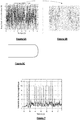
- FIG. 6A the temporal evolution of a triaxial acceleration measured by a sensor along a convoy course as partially represented in FIG. Figure 6C .
- This course has a 180 ° turn.
- the Figure 6B represents a zoom of this acceleration curve between the instants 11.4s and 12s.
- On the zoom of the Figure 6C we can observe a stationary phase, that is to say a plateau, of acceleration around the instant 11.7s.
- This acceleration plate is the imprint of a turn in the convoy course.
- the table T is created and stored in the memory 201 of the analysis device 20 during a step E0 for configuring the analysis device.
- This configuration E0 can be executed during a coupling of the analysis device 20 with the convoy machine M.
- the memory 202 contains data relating to a predetermined spatial representation relating to the convoy machine M.
- This spatial representation comprises spatial data relating to the machine, in particular to the convoy course or to the plurality of convoy courses it contains. These spatial data can be represented in the form of a map or a plan of the convoy machine M. This map or plan shows the characteristics of the convoy course (s): straight sections, turns, engines, etc.
- the data relating to the spatial representation of the convoy machine M are recorded in the memory 202 during the configuration E0 of the analysis device and the coupling thereof to the convoy machine M.
- the measuring system or instrument 1 is placed on a control object OB 0 and fixed thereto by a double-sided tape or by any other suitable fastening means.
- the control object OB 0 corresponds to an object able to be conveyed by the convoy machine M. It is for example a package, in the case of an application to sort parcels, a letter, in the case of a application to postal sorting, waste, or a motor vehicle structure in the case of an application to a production line or automotive assembly.
- control object thus instrumented is then inserted into the convoy machine M, at the entrance thereof, during a step E2.
- the method then comprises a convoy step E3, during which the instrumented control object is transported by the convoy machine M along a convoy path PC.
- FIG. 1 As an illustrative example, there is shown a portion of a convoy course comprising three sections T1, T2 and T3. Each section of the convoy course corresponds to a course module.
- the three sections T1, T2 and T3 are horizontal.
- the arrows F1 and F2 represent the direction of movement of an object along the path.
- the first section T1 is linear, horizontal and passes close to three successive motors M 1 , M 2 , M 3 .
- the second section T2 has two turns and passes close to two engines M 4 , located just before the first turn, M 5 , located just after the second turn, in the direction of movement of the object.
- the third section T3 is linear and passes close to three successive motors M 6 , M 7 , M 8 .
- the measured data, magnetic field (DATA_H), distance (DATA_d) and acceleration (DATA_a-3A), are recorded in the memory 6 of the measuring system 1, during a step E5.
- the object OB 1 is taken out of the convoy machine M, during a step E6.
- the measuring system 1 is separate from the control object OB 0 .
- the recorded measurement data (DATA_H, DATA_d, DATA_a-3A) are transmitted to the analysis device 20, here after physical connection of the system 1 to the analysis device 20.
- the measurement data transmitted by the system 1 are received via the communication interface 200 and stored in the memory 203 of the analysis device 20.
- the method then proceeds to an operation E8 for analyzing the recorded measurement data.
- the analysis operation comprises a step E80 of recognition or identification of fingerprints in the temporal evolution of the different measured physical quantities.
- This step E80 is implemented by the module 204 of fingerprint recognition.
- an imprint corresponds to a path characteristic.
- the step of recognizing fingerprints E80 is performed using the data table T stored in the memory 201 of the analysis device 20.
- the data table T could, alternatively, be accessible by the device 20 through a network such as the Internet.
- the method then comprises a step E81 for determining a chronology C_OB 1 of path characteristics corresponding to successive recognized fingerprints.
- This chronology C_OB 1 corresponds ultimately to the characteristics of the course as perceived by the instrumented object OB 1 .
- Step E81 is implemented by module 205 of the analysis device.
- each characteristic of the succession of determined path characteristics can be associated with time data corresponding to the instant at which the object OB 1 perceived or detected the path characteristic considered or the time window during which object OB 1 has perceived or detected the characteristic of course considered.
- the C_OB 1 timeline might contain only one succession (ie, an ordered sequence) of course characteristics.
- the method then comprises a step E82 for locating the instrumented object OB 1 .
- This step E82 is implemented by the location module 206 of the analysis device 20.
- a correspondence is established between the determined chronology C_OB 1 and the predetermined spatial representation RS relative to the convoy machine. M. This correspondence makes it possible to determine the position of the object OB 1 in the convoy machine M and more particularly along its convoy course, at each instant of the convoy of the object OB 1 .
- the convoy machine M may comprise several possible convoy routes.
- the location step E82 makes it possible to determine, from among all the possible paths, the path taken by the object OB 1 .
- the chronology C_OB 1 is determined. This chronology could be determined only partially. One could for example determine only the part of the chronology between the beginning of the convoy and the instant t.
- the chronology C_OB 1 comprises, between a convoy start time and the instant t, the following course characteristics: three successive engines close to the course, followed by a module change.
- a correspondence between the determined chronology C_OB 1 (or the determined part of chronology) and the predetermined spatial representation relating to the convoy machine M is determined. It can be deduced from this that, at the instant t the object OB 1 is at the beginning of the section T2 on the spatial representation.
- the method may then comprise a step E9 for controlling the proper operation of the convoy machine M.
- This step E9 is implemented by the control module 207 of the analysis device.
- the operation control of the convoy machine M can be performed from the determined path characteristics chronology C_OB 1 . It can consist in checking if the object OB 1 borrows the good course, among a set of the possible courses. It may also consist in checking whether the convoy speed of the object OB 1 along its convoy course, or part of this course, conforms to a desired speed. It can also consist in verifying that the object OB 1 follows correctly the convoy course, that is to say that it complies with certain predefined convoy conditions or parameters.
- the method may also comprise a step E10 for detecting an anomaly in the convoy course of the object OB 1 .
- This detection step E10 is implemented by the detection module 208 of the analysis device.
- the anomaly detection may be based on an analysis of the temporal evolution of a particular physical quantity measured by the measurement system 1 during the transport of the object OB 1 along the convoy course. For example, it may be the inclination, including the inclination of a vector arbitrary, fixed and attached to the conveyed object, relative to the plane orthogonal to the direction of the earth's gravity field (or horizontal plane). of the object, defined for example with respect to a horizontal plane.
Landscapes
- Life Sciences & Earth Sciences (AREA)
- Chemical & Material Sciences (AREA)
- Health & Medical Sciences (AREA)
- Physics & Mathematics (AREA)
- General Physics & Mathematics (AREA)
- Biochemistry (AREA)
- Medicinal Chemistry (AREA)
- Analytical Chemistry (AREA)
- Food Science & Technology (AREA)
- General Health & Medical Sciences (AREA)
- Engineering & Computer Science (AREA)
- Immunology (AREA)
- Pathology (AREA)
- General Life Sciences & Earth Sciences (AREA)
- Geophysics (AREA)
- Length Measuring Devices With Unspecified Measuring Means (AREA)
- Control Of Conveyors (AREA)
Claims (15)
- Verfahren zur Ortung eines instrumentierten Objekts (OB1), das von einer Fördermaschine (M) entlang eines Pfades (PC) transportiert wird, wobei das Objekt (OB1) mit einem System zur Messung (1) wenigstens einer gegebenen physikalischen Größe ausgestattet ist, umfassend: einen Schritt der Messung (E4), durch das Messsystem (1), des zeitlichen Verlaufs der physikalischen Größe während des Transports des Objekts (OB1) entlang des Förderpfades (PC), einen Schritt (E80) der Erkennung mehrerer Abdrücke, wobei jeder Abdruck einem Pfadmerkmal im gemessenen zeitlichen Verlauf der physikalischen Größe entspricht, einen Schritt (E81) der Bestimmung einer zeitlichen Abfolge von Pfadmerkmalen (C_OB1), die einer Aufeinanderfolge von erkannten Abdrücken entspricht, und einen Schritt (E82) der Ortung des Objekts (OB1), in welchem eine Entsprechung zwischen der bestimmten zeitlichen Abfolge von Pfadmerkmalen und einer vorbestimmten räumlichen Darstellung, die sich auf die Fördermaschine (M) bezieht, bestimmt wird.
- Verfahren nach dem vorhergehenden Anspruch, dadurch gekennzeichnet, dass der zeitliche Verlauf wenigstens einer der physikalischen Größen der Gruppe gemessen wird, die eine Beschleunigung, eine Entfernung, eine Neigung, ein Magnetfeld, eine Winkelposition, eine Temperatur, einen Ton und einen Druck umfasst.
- Verfahren nach Anspruch 1 oder 2, dadurch gekennzeichnet, dass die Aufeinanderfolge von erkannten Abdrücken verschiedene Typen von Abdrücken umfasst, insbesondere Abdrücke der Gruppe, die eine Beschleunigung, eine Entfernung, eine Neigung, ein Magnetfeld, eine Winkelposition, eine Temperatur, einen Ton und einen Druck umfasst.
- Verfahren nach einem der vorhergehenden Ansprüche, dadurch gekennzeichnet, dass im Schritt der Erkennung (E80) wenigstens einer der Abdrücke der Gruppe erkannt wird, die einen Spitzenwert der gemessenen magnetischen Feldstärke, der einem Elektromotor entspricht, einen Spitzenwert der gemessenen Entfernung, der einem Übergang von einem Modul zu einem anderen Modul der Fördermaschine (M) entspricht, und ein Plateau einer gemessenen Beschleunigung, das einer Kurve entspricht, umfasst.
- Verfahren nach einem der vorhergehenden Ansprüche, dadurch gekennzeichnet, dass die zeitlichen Verläufe mehrerer physikalischer Größen gemessen werden (E4).
- Verfahren nach einem der vorhergehenden Ansprüche, dadurch gekennzeichnet, dass der Schritt der Erkennung (E80) mithilfe einer Datentabelle (T) durchgeführt wird, die für jedes Merkmal einer Menge von vordefinierten Pfadmerkmalen Charakterisierungsdaten des Abdrucks enthält, der dem betreffenden Pfadmerkmal entspricht.
- Verfahren nach einem der vorhergehenden Ansprüche, dadurch gekennzeichnet, dass, wenn die Fördermaschine (M) mehrere mögliche Förderpfade aufweist, im Schritt der Ortung (E82) der Pfad, der von dem instrumentierten Objekt benutzt wird, unter den mehreren möglichen Förderpfaden anhand der bestimmten zeitlichen Abfolge von Pfadmerkmalen bestimmt wird.
- Verfahren nach einem der vorhergehenden Ansprüche, dadurch gekennzeichnet, dass es einen Schritt (E9) der Kontrolle der ordnungsgemäßen Funktionsweise Fördermaschine (M) anhand der bestimmten zeitlichen Abfolge von Pfadmerkmalen (C_OB1) umfasst.
- Verfahren nach dem vorhergehenden Anspruch, dadurch gekennzeichnet, dass es einen Schritt (E10) der Detektion einer Anomalie im Förderpfad des Objekts umfasst, der auf einer Analyse des zeitlichen Verlaufs einer speziellen gemessenen physikalischen Größe basiert.
- Verfahren nach einem der vorhergehenden Ansprüche, dadurch gekennzeichnet, dass es einen Schritt (E7) der Übertragung von Daten des gemessenen Verlaufs der physikalischen Größe zu einer externen Analysevorrichtung (20) umfasst und die Schritte (E80) der Erkennung wenigstens eines Abdrucks und der Ortung (E82) des Objekts (OB1) von der externen Analysevorrichtung (20) ausgeführt werden.
- Analysevorrichtung, welche dazu bestimmt ist, ein instrumentiertes Objekt zu orten, das von einer Fördermaschine (M) entlang eines Pfades (PC) transportiert wird, wobei das Objekt mit einem System zur Messung (1) wenigstens einer gegebenen physikalischen Größe ausgestattet ist, das dafür ausgelegt ist, den zeitlichen Verlauf der physikalischen Größe während des Transports des Objekts entlang des Förderpfades (PC) zu messen, wobei die Analysevorrichtung umfasst: eine Schnittstelle zur Kommunikation mit dem Messsystem, die dazu bestimmt ist, Messdaten zu empfangen, die sich auf den zeitlichen Verlauf der physikalischen Größe während des Transports des Objekts entlang des Förderpfades beziehen, ein Erkennungsmodul (204), das geeignet ist, mehrere Abdrücke zu erkennen, wobei jeder Abdruck einem Pfadmerkmal im gemessenen zeitlichen Verlauf der physikalischen Größe entspricht, ein Modul (205) zur Bestimmung einer zeitlichen Abfolge von Pfadmerkmalen, die einer Aufeinanderfolge von erkannten Abdrücken entspricht, und ein Modul (206) zur Ortung des Objekts, das geeignet ist, eine Entsprechung zwischen der bestimmten zeitlichen Abfolge von Pfadmerkmalen und einer in einem Speicher gespeicherten vorbestimmten räumlichen Darstellung, die sich auf die Fördermaschine (M) bezieht, herzustellen.
- System zur Ortung eines Objekts, das von einer Fördermaschine (M) entlang eines Pfades (PC) transportiert wird, dadurch gekennzeichnet, dass es ein instrumentiertes Objekt (OB1), das mit einem System (1) zur Messung wenigstens einer gegebenen physikalischen Größe ausgestattet ist, das dafür ausgelegt ist, den zeitlichen Verlauf der physikalischen Größe während des Transports des Objekts entlang des Förderpfades (PC) zu messen, und eine externe Analysevorrichtung (20) nach dem vorhergehenden Anspruch umfasst.
- System nach Anspruch 12, dadurch gekennzeichnet, dass die externe Analysevorrichtung (20) einen Speicher (201) zur Speicherung einer Datentabelle (T) umfasst, die für jedes Merkmal einer Menge von vordefinierten Pfadmerkmalen Charakterisierungsdaten des Abdrucks enthält, der dem betreffenden Pfadmerkmal entspricht.
- System nach einem der Ansprüche 12 und 13, dadurch gekennzeichnet, dass die externe Analysevorrichtung (20) ein Modul (207) zur Kontrolle der ordnungsgemäßen Funktionsweise der Fördermaschine (M) anhand der bestimmten zeitlichen Abfolge von Pfadmerkmalen umfasst.
- System nach einem der Ansprüche 12 bis 14, dadurch gekennzeichnet, dass es ein Modul (208) zur Detektion einer Anomalie umfasst, das dafür ausgelegt ist, eine Anomalie im Förderpfad des Objekts (OB1) durch Analyse des zeitlichen Verlaufs einer speziellen gemessenen physikalischen Größe zu detektieren.
Applications Claiming Priority (2)
| Application Number | Priority Date | Filing Date | Title |
|---|---|---|---|
| FR1462311A FR3030051A1 (fr) | 2014-12-12 | 2014-12-12 | Procede et systeme de localisation d'un objet instrumente transporte le long d'un parcours par une machine de convoi |
| PCT/EP2015/079381 WO2016092064A1 (fr) | 2014-12-12 | 2015-12-11 | Procede et systeme de localisation d'un objet instrumente transporte le long d'un parcours par une machine de convoi |
Publications (2)
| Publication Number | Publication Date |
|---|---|
| EP3230182A1 EP3230182A1 (de) | 2017-10-18 |
| EP3230182B1 true EP3230182B1 (de) | 2019-01-30 |
Family
ID=52469176
Family Applications (1)
| Application Number | Title | Priority Date | Filing Date |
|---|---|---|---|
| EP15817119.9A Not-in-force EP3230182B1 (de) | 2014-12-12 | 2015-12-11 | Verfahren und system zur ortung eines instrumentierten objekts, das von einer fördermaschine entlang eines pfads transportiert wird |
Country Status (4)
| Country | Link |
|---|---|
| US (1) | US10947055B2 (de) |
| EP (1) | EP3230182B1 (de) |
| FR (1) | FR3030051A1 (de) |
| WO (1) | WO2016092064A1 (de) |
Family Cites Families (8)
| Publication number | Priority date | Publication date | Assignee | Title |
|---|---|---|---|---|
| US7948381B2 (en) * | 2004-04-30 | 2011-05-24 | Binforma Group Limited Liability Company | Reversibly deactivating a radio frequency identification data tag |
| BRPI0618941A2 (pt) * | 2005-11-23 | 2011-09-13 | Frost Links Inc | dispositivo de medição para circuito condutor |
| US8260574B1 (en) * | 2007-12-21 | 2012-09-04 | Dematic Corp. | Diagnostic device for material handling system and method of diagnosing |
| US7982764B2 (en) * | 2008-07-08 | 2011-07-19 | United Parcel Service Of America, Inc. | Apparatus for monitoring a package handling system |
| WO2010031780A1 (en) * | 2008-09-16 | 2010-03-25 | Basf Plant Science Gmbh | Method for improved plant breeding |
| US8077050B2 (en) * | 2009-03-24 | 2011-12-13 | United Parcel Service Of America, Inc. | Transport system evaluator |
| DE102011003682A1 (de) * | 2011-02-07 | 2012-08-09 | Robert Bosch Gmbh | Transportvorrichtung mit Erkennungsfunktion |
| DE102011011625A1 (de) * | 2011-02-17 | 2012-08-23 | Krones Aktiengesellschaft | Vorrichtung und Verfahren zum Transportieren von Behältnissen oder Behältnisgebinden mit drahtloser Zustandserfassung |
-
2014
- 2014-12-12 FR FR1462311A patent/FR3030051A1/fr not_active Ceased
-
2015
- 2015-12-11 EP EP15817119.9A patent/EP3230182B1/de not_active Not-in-force
- 2015-12-11 US US15/533,467 patent/US10947055B2/en not_active Expired - Fee Related
- 2015-12-11 WO PCT/EP2015/079381 patent/WO2016092064A1/fr not_active Ceased
Non-Patent Citations (1)
| Title |
|---|
| None * |
Also Published As
| Publication number | Publication date |
|---|---|
| WO2016092064A1 (fr) | 2016-06-16 |
| FR3030051A1 (fr) | 2016-06-17 |
| EP3230182A1 (de) | 2017-10-18 |
| US10947055B2 (en) | 2021-03-16 |
| US20170334657A1 (en) | 2017-11-23 |
Similar Documents
| Publication | Publication Date | Title |
|---|---|---|
| EP1429277B1 (de) | Identifizierungsverkleidung für zu sortierende Gegenstände | |
| US10875496B2 (en) | Vehicle load prediction | |
| US11821728B2 (en) | Devices, systems and methods for evaluating objects subject to repair or other alteration | |
| US11270247B2 (en) | System for routing articles by individuals who are members of a community, carrying out a control of the contents by imaging during transfer of the package between individuals | |
| CA2592058A1 (en) | Method for the securing and monitoring of containers and container with securing and monitoring means | |
| EP1429272B1 (de) | System zum Ansammeln und zur automatischen Prüfung von Bestellungen von Waren | |
| EP3399281B1 (de) | Kalibrierung der sensoreinheitausrichtung zur verwendung in einem fahrzeugüberwachungssystem | |
| US8994504B1 (en) | Utilization of motion and spatial identification in mobile RFID interrogator | |
| JP2008518336A5 (de) | ||
| CN110082790A (zh) | 一种面向移动终端的卫星欺骗识别方法、装置及系统 | |
| CN109102227A (zh) | 行李类别检测方法、自助行李设备和存储介质 | |
| KR101613120B1 (ko) | 바코드 검사 시스템 | |
| FR2976701A1 (fr) | Systeme de distribution de bouteilles de gaz comprenant des moyens d'identification du type de bouteille comportant un capteur de couleur et un capteur de detection de materiau ferromagnetique | |
| FR2826731A1 (fr) | Procede de localisation de capteurs montes chacun sur une roue de vehicule. | |
| EP3230182B1 (de) | Verfahren und system zur ortung eines instrumentierten objekts, das von einer fördermaschine entlang eines pfads transportiert wird | |
| EP2271946B1 (de) | EINRICHTUNG ZUM DETEKTIEREN EINES StOß-EREIGNISSES UND ZUGEHÖRIGES MOBILSYSTEM | |
| EP4502897A1 (de) | Paketverfolgungssystem | |
| EP2791687B1 (de) | Verfahren und system zur automatischen kalibrierung einer vorrichtung zur messung der geschwindigkeit eines sich in einem dreidimensionalen raum bewegenden fahrzeugs | |
| WO2002007014A1 (en) | Data logger for monitoring a consignment of goods | |
| US12059073B1 (en) | Apparatus for stowing items | |
| EP2416287A2 (de) | System zur Lokalisierung eines Geräts in einem Computerraum | |
| CN215725976U (zh) | 车辆及用于车辆的导航定位设备 | |
| EP4094179A1 (de) | System zur überwachung des be- und entladens oder des flächentransfers von waren | |
| WO2019170863A1 (fr) | Procede de detection d'anomalie dans la perception par un vehicule automobile de son environnement | |
| WO2026057674A1 (fr) | Procédé et dispositif de vérification de la conformité du sens de pose d'objets placés en pile |
Legal Events
| Date | Code | Title | Description |
|---|---|---|---|
| STAA | Information on the status of an ep patent application or granted ep patent |
Free format text: STATUS: THE INTERNATIONAL PUBLICATION HAS BEEN MADE |
|
| PUAI | Public reference made under article 153(3) epc to a published international application that has entered the european phase |
Free format text: ORIGINAL CODE: 0009012 |
|
| STAA | Information on the status of an ep patent application or granted ep patent |
Free format text: STATUS: REQUEST FOR EXAMINATION WAS MADE |
|
| 17P | Request for examination filed |
Effective date: 20170602 |
|
| AK | Designated contracting states |
Kind code of ref document: A1 Designated state(s): AL AT BE BG CH CY CZ DE DK EE ES FI FR GB GR HR HU IE IS IT LI LT LU LV MC MK MT NL NO PL PT RO RS SE SI SK SM TR |
|
| AX | Request for extension of the european patent |
Extension state: BA ME |
|
| DAV | Request for validation of the european patent (deleted) | ||
| DAX | Request for extension of the european patent (deleted) | ||
| GRAP | Despatch of communication of intention to grant a patent |
Free format text: ORIGINAL CODE: EPIDOSNIGR1 |
|
| STAA | Information on the status of an ep patent application or granted ep patent |
Free format text: STATUS: GRANT OF PATENT IS INTENDED |
|
| INTG | Intention to grant announced |
Effective date: 20180803 |
|
| GRAS | Grant fee paid |
Free format text: ORIGINAL CODE: EPIDOSNIGR3 |
|
| GRAA | (expected) grant |
Free format text: ORIGINAL CODE: 0009210 |
|
| STAA | Information on the status of an ep patent application or granted ep patent |
Free format text: STATUS: THE PATENT HAS BEEN GRANTED |
|
| AK | Designated contracting states |
Kind code of ref document: B1 Designated state(s): AL AT BE BG CH CY CZ DE DK EE ES FI FR GB GR HR HU IE IS IT LI LT LU LV MC MK MT NL NO PL PT RO RS SE SI SK SM TR |
|
| REG | Reference to a national code |
Ref country code: GB Ref legal event code: FG4D Free format text: NOT ENGLISH |
|
| REG | Reference to a national code |
Ref country code: CH Ref legal event code: EP |
|
| REG | Reference to a national code |
Ref country code: AT Ref legal event code: REF Ref document number: 1093078 Country of ref document: AT Kind code of ref document: T Effective date: 20190215 |
|
| REG | Reference to a national code |
Ref country code: IE Ref legal event code: FG4D Free format text: LANGUAGE OF EP DOCUMENT: FRENCH |
|
| REG | Reference to a national code |
Ref country code: DE Ref legal event code: R096 Ref document number: 602015024157 Country of ref document: DE |
|
| REG | Reference to a national code |
Ref country code: LT Ref legal event code: MG4D |
|
| REG | Reference to a national code |
Ref country code: NL Ref legal event code: MP Effective date: 20190130 |
|
| PG25 | Lapsed in a contracting state [announced via postgrant information from national office to epo] |
Ref country code: NO Free format text: LAPSE BECAUSE OF FAILURE TO SUBMIT A TRANSLATION OF THE DESCRIPTION OR TO PAY THE FEE WITHIN THE PRESCRIBED TIME-LIMIT Effective date: 20190430 Ref country code: LT Free format text: LAPSE BECAUSE OF FAILURE TO SUBMIT A TRANSLATION OF THE DESCRIPTION OR TO PAY THE FEE WITHIN THE PRESCRIBED TIME-LIMIT Effective date: 20190130 Ref country code: FI Free format text: LAPSE BECAUSE OF FAILURE TO SUBMIT A TRANSLATION OF THE DESCRIPTION OR TO PAY THE FEE WITHIN THE PRESCRIBED TIME-LIMIT Effective date: 20190130 Ref country code: NL Free format text: LAPSE BECAUSE OF FAILURE TO SUBMIT A TRANSLATION OF THE DESCRIPTION OR TO PAY THE FEE WITHIN THE PRESCRIBED TIME-LIMIT Effective date: 20190130 Ref country code: PT Free format text: LAPSE BECAUSE OF FAILURE TO SUBMIT A TRANSLATION OF THE DESCRIPTION OR TO PAY THE FEE WITHIN THE PRESCRIBED TIME-LIMIT Effective date: 20190530 Ref country code: ES Free format text: LAPSE BECAUSE OF FAILURE TO SUBMIT A TRANSLATION OF THE DESCRIPTION OR TO PAY THE FEE WITHIN THE PRESCRIBED TIME-LIMIT Effective date: 20190130 Ref country code: SE Free format text: LAPSE BECAUSE OF FAILURE TO SUBMIT A TRANSLATION OF THE DESCRIPTION OR TO PAY THE FEE WITHIN THE PRESCRIBED TIME-LIMIT Effective date: 20190130 Ref country code: PL Free format text: LAPSE BECAUSE OF FAILURE TO SUBMIT A TRANSLATION OF THE DESCRIPTION OR TO PAY THE FEE WITHIN THE PRESCRIBED TIME-LIMIT Effective date: 20190130 |
|
| REG | Reference to a national code |
Ref country code: AT Ref legal event code: MK05 Ref document number: 1093078 Country of ref document: AT Kind code of ref document: T Effective date: 20190130 |
|
| PG25 | Lapsed in a contracting state [announced via postgrant information from national office to epo] |
Ref country code: GR Free format text: LAPSE BECAUSE OF FAILURE TO SUBMIT A TRANSLATION OF THE DESCRIPTION OR TO PAY THE FEE WITHIN THE PRESCRIBED TIME-LIMIT Effective date: 20190501 Ref country code: HR Free format text: LAPSE BECAUSE OF FAILURE TO SUBMIT A TRANSLATION OF THE DESCRIPTION OR TO PAY THE FEE WITHIN THE PRESCRIBED TIME-LIMIT Effective date: 20190130 Ref country code: IS Free format text: LAPSE BECAUSE OF FAILURE TO SUBMIT A TRANSLATION OF THE DESCRIPTION OR TO PAY THE FEE WITHIN THE PRESCRIBED TIME-LIMIT Effective date: 20190530 Ref country code: LV Free format text: LAPSE BECAUSE OF FAILURE TO SUBMIT A TRANSLATION OF THE DESCRIPTION OR TO PAY THE FEE WITHIN THE PRESCRIBED TIME-LIMIT Effective date: 20190130 Ref country code: BG Free format text: LAPSE BECAUSE OF FAILURE TO SUBMIT A TRANSLATION OF THE DESCRIPTION OR TO PAY THE FEE WITHIN THE PRESCRIBED TIME-LIMIT Effective date: 20190430 Ref country code: RS Free format text: LAPSE BECAUSE OF FAILURE TO SUBMIT A TRANSLATION OF THE DESCRIPTION OR TO PAY THE FEE WITHIN THE PRESCRIBED TIME-LIMIT Effective date: 20190130 |
|
| PG25 | Lapsed in a contracting state [announced via postgrant information from national office to epo] |
Ref country code: CZ Free format text: LAPSE BECAUSE OF FAILURE TO SUBMIT A TRANSLATION OF THE DESCRIPTION OR TO PAY THE FEE WITHIN THE PRESCRIBED TIME-LIMIT Effective date: 20190130 Ref country code: IT Free format text: LAPSE BECAUSE OF FAILURE TO SUBMIT A TRANSLATION OF THE DESCRIPTION OR TO PAY THE FEE WITHIN THE PRESCRIBED TIME-LIMIT Effective date: 20190130 Ref country code: RO Free format text: LAPSE BECAUSE OF FAILURE TO SUBMIT A TRANSLATION OF THE DESCRIPTION OR TO PAY THE FEE WITHIN THE PRESCRIBED TIME-LIMIT Effective date: 20190130 Ref country code: SK Free format text: LAPSE BECAUSE OF FAILURE TO SUBMIT A TRANSLATION OF THE DESCRIPTION OR TO PAY THE FEE WITHIN THE PRESCRIBED TIME-LIMIT Effective date: 20190130 Ref country code: EE Free format text: LAPSE BECAUSE OF FAILURE TO SUBMIT A TRANSLATION OF THE DESCRIPTION OR TO PAY THE FEE WITHIN THE PRESCRIBED TIME-LIMIT Effective date: 20190130 Ref country code: AL Free format text: LAPSE BECAUSE OF FAILURE TO SUBMIT A TRANSLATION OF THE DESCRIPTION OR TO PAY THE FEE WITHIN THE PRESCRIBED TIME-LIMIT Effective date: 20190130 Ref country code: DK Free format text: LAPSE BECAUSE OF FAILURE TO SUBMIT A TRANSLATION OF THE DESCRIPTION OR TO PAY THE FEE WITHIN THE PRESCRIBED TIME-LIMIT Effective date: 20190130 |
|
| REG | Reference to a national code |
Ref country code: DE Ref legal event code: R097 Ref document number: 602015024157 Country of ref document: DE |
|
| PG25 | Lapsed in a contracting state [announced via postgrant information from national office to epo] |
Ref country code: SM Free format text: LAPSE BECAUSE OF FAILURE TO SUBMIT A TRANSLATION OF THE DESCRIPTION OR TO PAY THE FEE WITHIN THE PRESCRIBED TIME-LIMIT Effective date: 20190130 |
|
| PLBE | No opposition filed within time limit |
Free format text: ORIGINAL CODE: 0009261 |
|
| STAA | Information on the status of an ep patent application or granted ep patent |
Free format text: STATUS: NO OPPOSITION FILED WITHIN TIME LIMIT |
|
| PG25 | Lapsed in a contracting state [announced via postgrant information from national office to epo] |
Ref country code: AT Free format text: LAPSE BECAUSE OF FAILURE TO SUBMIT A TRANSLATION OF THE DESCRIPTION OR TO PAY THE FEE WITHIN THE PRESCRIBED TIME-LIMIT Effective date: 20190130 |
|
| 26N | No opposition filed |
Effective date: 20191031 |
|
| PG25 | Lapsed in a contracting state [announced via postgrant information from national office to epo] |
Ref country code: SI Free format text: LAPSE BECAUSE OF FAILURE TO SUBMIT A TRANSLATION OF THE DESCRIPTION OR TO PAY THE FEE WITHIN THE PRESCRIBED TIME-LIMIT Effective date: 20190130 |
|
| PG25 | Lapsed in a contracting state [announced via postgrant information from national office to epo] |
Ref country code: TR Free format text: LAPSE BECAUSE OF FAILURE TO SUBMIT A TRANSLATION OF THE DESCRIPTION OR TO PAY THE FEE WITHIN THE PRESCRIBED TIME-LIMIT Effective date: 20190130 |
|
| REG | Reference to a national code |
Ref country code: CH Ref legal event code: PL |
|
| REG | Reference to a national code |
Ref country code: BE Ref legal event code: MM Effective date: 20191231 |
|
| PG25 | Lapsed in a contracting state [announced via postgrant information from national office to epo] |
Ref country code: MC Free format text: LAPSE BECAUSE OF FAILURE TO SUBMIT A TRANSLATION OF THE DESCRIPTION OR TO PAY THE FEE WITHIN THE PRESCRIBED TIME-LIMIT Effective date: 20190130 |
|
| PG25 | Lapsed in a contracting state [announced via postgrant information from national office to epo] |
Ref country code: IE Free format text: LAPSE BECAUSE OF NON-PAYMENT OF DUE FEES Effective date: 20191211 Ref country code: LU Free format text: LAPSE BECAUSE OF NON-PAYMENT OF DUE FEES Effective date: 20191211 |
|
| PG25 | Lapsed in a contracting state [announced via postgrant information from national office to epo] |
Ref country code: LI Free format text: LAPSE BECAUSE OF NON-PAYMENT OF DUE FEES Effective date: 20191231 Ref country code: CH Free format text: LAPSE BECAUSE OF NON-PAYMENT OF DUE FEES Effective date: 20191231 Ref country code: BE Free format text: LAPSE BECAUSE OF NON-PAYMENT OF DUE FEES Effective date: 20191231 |
|
| PG25 | Lapsed in a contracting state [announced via postgrant information from national office to epo] |
Ref country code: CY Free format text: LAPSE BECAUSE OF FAILURE TO SUBMIT A TRANSLATION OF THE DESCRIPTION OR TO PAY THE FEE WITHIN THE PRESCRIBED TIME-LIMIT Effective date: 20190130 |
|
| PG25 | Lapsed in a contracting state [announced via postgrant information from national office to epo] |
Ref country code: MT Free format text: LAPSE BECAUSE OF FAILURE TO SUBMIT A TRANSLATION OF THE DESCRIPTION OR TO PAY THE FEE WITHIN THE PRESCRIBED TIME-LIMIT Effective date: 20190130 Ref country code: HU Free format text: LAPSE BECAUSE OF FAILURE TO SUBMIT A TRANSLATION OF THE DESCRIPTION OR TO PAY THE FEE WITHIN THE PRESCRIBED TIME-LIMIT; INVALID AB INITIO Effective date: 20151211 |
|
| PG25 | Lapsed in a contracting state [announced via postgrant information from national office to epo] |
Ref country code: MK Free format text: LAPSE BECAUSE OF FAILURE TO SUBMIT A TRANSLATION OF THE DESCRIPTION OR TO PAY THE FEE WITHIN THE PRESCRIBED TIME-LIMIT Effective date: 20190130 |
|
| PGFP | Annual fee paid to national office [announced via postgrant information from national office to epo] |
Ref country code: GB Payment date: 20221219 Year of fee payment: 8 Ref country code: FR Payment date: 20221220 Year of fee payment: 8 Ref country code: DE Payment date: 20221209 Year of fee payment: 8 |
|
| REG | Reference to a national code |
Ref country code: DE Ref legal event code: R119 Ref document number: 602015024157 Country of ref document: DE |
|
| GBPC | Gb: european patent ceased through non-payment of renewal fee |
Effective date: 20231211 |
|
| PG25 | Lapsed in a contracting state [announced via postgrant information from national office to epo] |
Ref country code: DE Free format text: LAPSE BECAUSE OF NON-PAYMENT OF DUE FEES Effective date: 20240702 |
|
| PG25 | Lapsed in a contracting state [announced via postgrant information from national office to epo] |
Ref country code: GB Free format text: LAPSE BECAUSE OF NON-PAYMENT OF DUE FEES Effective date: 20231211 |
|
| PG25 | Lapsed in a contracting state [announced via postgrant information from national office to epo] |
Ref country code: FR Free format text: LAPSE BECAUSE OF NON-PAYMENT OF DUE FEES Effective date: 20231231 |
|
| PG25 | Lapsed in a contracting state [announced via postgrant information from national office to epo] |
Ref country code: GB Free format text: LAPSE BECAUSE OF NON-PAYMENT OF DUE FEES Effective date: 20231211 Ref country code: FR Free format text: LAPSE BECAUSE OF NON-PAYMENT OF DUE FEES Effective date: 20231231 Ref country code: DE Free format text: LAPSE BECAUSE OF NON-PAYMENT OF DUE FEES Effective date: 20240702 |