EP3230102B1 - Groupe motopropulseur electrique refroidi par air - Google Patents
Groupe motopropulseur electrique refroidi par air Download PDFInfo
- Publication number
- EP3230102B1 EP3230102B1 EP15780928.6A EP15780928A EP3230102B1 EP 3230102 B1 EP3230102 B1 EP 3230102B1 EP 15780928 A EP15780928 A EP 15780928A EP 3230102 B1 EP3230102 B1 EP 3230102B1
- Authority
- EP
- European Patent Office
- Prior art keywords
- electric motor
- air
- powertrain
- casing
- speed reducer
- Prior art date
- Legal status (The legal status is an assumption and is not a legal conclusion. Google has not performed a legal analysis and makes no representation as to the accuracy of the status listed.)
- Active
Links
- 238000001816 cooling Methods 0.000 claims description 29
- 238000011144 upstream manufacturing Methods 0.000 claims description 20
- 239000003638 chemical reducing agent Substances 0.000 claims description 16
- 230000005465 channeling Effects 0.000 claims description 4
- 239000000428 dust Substances 0.000 description 2
- 230000002093 peripheral effect Effects 0.000 description 2
- 238000007599 discharging Methods 0.000 description 1
- 238000004870 electrical engineering Methods 0.000 description 1
- 238000011176 pooling Methods 0.000 description 1
- 230000001681 protective effect Effects 0.000 description 1
- 230000035939 shock Effects 0.000 description 1
- XLYOFNOQVPJJNP-UHFFFAOYSA-N water Substances O XLYOFNOQVPJJNP-UHFFFAOYSA-N 0.000 description 1
Images


Classifications
-
- B—PERFORMING OPERATIONS; TRANSPORTING
- B60—VEHICLES IN GENERAL
- B60K—ARRANGEMENT OR MOUNTING OF PROPULSION UNITS OR OF TRANSMISSIONS IN VEHICLES; ARRANGEMENT OR MOUNTING OF PLURAL DIVERSE PRIME-MOVERS IN VEHICLES; AUXILIARY DRIVES FOR VEHICLES; INSTRUMENTATION OR DASHBOARDS FOR VEHICLES; ARRANGEMENTS IN CONNECTION WITH COOLING, AIR INTAKE, GAS EXHAUST OR FUEL SUPPLY OF PROPULSION UNITS IN VEHICLES
- B60K11/00—Arrangement in connection with cooling of propulsion units
- B60K11/06—Arrangement in connection with cooling of propulsion units with air cooling
-
- B—PERFORMING OPERATIONS; TRANSPORTING
- B60—VEHICLES IN GENERAL
- B60K—ARRANGEMENT OR MOUNTING OF PROPULSION UNITS OR OF TRANSMISSIONS IN VEHICLES; ARRANGEMENT OR MOUNTING OF PLURAL DIVERSE PRIME-MOVERS IN VEHICLES; AUXILIARY DRIVES FOR VEHICLES; INSTRUMENTATION OR DASHBOARDS FOR VEHICLES; ARRANGEMENTS IN CONNECTION WITH COOLING, AIR INTAKE, GAS EXHAUST OR FUEL SUPPLY OF PROPULSION UNITS IN VEHICLES
- B60K1/00—Arrangement or mounting of electrical propulsion units
-
- H—ELECTRICITY
- H02—GENERATION; CONVERSION OR DISTRIBUTION OF ELECTRIC POWER
- H02K—DYNAMO-ELECTRIC MACHINES
- H02K5/00—Casings; Enclosures; Supports
- H02K5/04—Casings or enclosures characterised by the shape, form or construction thereof
- H02K5/20—Casings or enclosures characterised by the shape, form or construction thereof with channels or ducts for flow of cooling medium
- H02K5/207—Casings or enclosures characterised by the shape, form or construction thereof with channels or ducts for flow of cooling medium with openings in the casing specially adapted for ambient air
-
- H—ELECTRICITY
- H02—GENERATION; CONVERSION OR DISTRIBUTION OF ELECTRIC POWER
- H02K—DYNAMO-ELECTRIC MACHINES
- H02K9/00—Arrangements for cooling or ventilating
- H02K9/02—Arrangements for cooling or ventilating by ambient air flowing through the machine
- H02K9/04—Arrangements for cooling or ventilating by ambient air flowing through the machine having means for generating a flow of cooling medium
- H02K9/06—Arrangements for cooling or ventilating by ambient air flowing through the machine having means for generating a flow of cooling medium with fans or impellers driven by the machine shaft
-
- B—PERFORMING OPERATIONS; TRANSPORTING
- B60—VEHICLES IN GENERAL
- B60K—ARRANGEMENT OR MOUNTING OF PROPULSION UNITS OR OF TRANSMISSIONS IN VEHICLES; ARRANGEMENT OR MOUNTING OF PLURAL DIVERSE PRIME-MOVERS IN VEHICLES; AUXILIARY DRIVES FOR VEHICLES; INSTRUMENTATION OR DASHBOARDS FOR VEHICLES; ARRANGEMENTS IN CONNECTION WITH COOLING, AIR INTAKE, GAS EXHAUST OR FUEL SUPPLY OF PROPULSION UNITS IN VEHICLES
- B60K1/00—Arrangement or mounting of electrical propulsion units
- B60K2001/003—Arrangement or mounting of electrical propulsion units with means for cooling the electrical propulsion units
- B60K2001/006—Arrangement or mounting of electrical propulsion units with means for cooling the electrical propulsion units the electric motors
Definitions
- the present invention relates generally to the fields of electrical engineering and automotive, and more specifically relates to the cooling of an electric traction motor of an electric or hybrid vehicle.
- the cooling system of such a vehicle comprises a fan integrated with the electric motor, that is to say, sharing the rotor shaft of the electric motor.
- This fan has a risk of reliability because it sucks the dust and splash water from the exhaust duct of the cooling system.
- the air cooling of such a cooling system loses efficiency due to the pressure drop due in particular to the complexity of the air circuit for cooling the electric motor of the vehicle.
- the electric powertrain of the prior art have a large footprint in the direction of the axis of rotation of the electric motor, particularly due to the size of the engine cooling system. Such a powertrain therefore tends to extend forwardly in the front compartment of the vehicle, and to be vulnerable in the event of a frontal impact.
- an electric power train comprising an electric motor housed in a housing, and an air cooling circuit of the electric motor, the cooling circuit comprising an air inlet orifice and an air outlet orifice. in the crankcase of the electric motor, the cooling circuit further comprising a fan arranged at a height relative to the electric motor, an upstream duct channeling the air from the fan towards the electric motor, and a downstream duct for evacuating the air from the electric motor to the ground.
- One of the aims of the invention is to overcome at least some of the disadvantages of the prior art by providing a compact electric powertrain and whose air cooling is done efficiently, including a remote fan of the electric motor and located in height in relation to this one.
- the invention proposes an electric powertrain comprising a gearbox and an electric motor housed in contiguous casings, and an air cooling circuit of said reducer and said electric motor, said cooling circuit comprising an orifice of air inlet into the gearbox housing, air passage holes in a housing wall separating said gearhead from said electric motor, and an air outlet port in the housing of said electric motor, said cooling circuit including in addition to a fan disposed in height relative to said reducer and said electric motor, an upstream duct channeling the air from said fan to said reducer, and a downstream duct discharging air from said electric motor to the ground.
- the cooling circuit of the electric motor undergoes less pressure losses, due to the placement of the height of the fan of the cooling system.
- This configuration also makes reliable the operation of the fan and thus to overcome a protective device of the duct downstream exhaust air, which further reduces the pressure drop and simplifies the cooling system.
- the height placement of the fan also saves dust and moisture protection.
- a powertrain is obtained. compact transversely.
- Other powertrain components such as its power electronics that can be arranged vertically relative to the gearbox and motor unit, it reduces the vulnerability of the powertrain according to the invention during frontal impacts.
- said fan being disposed above the casing of said reducer or above the casing of said electric motor, said upstream duct has no radius of curvature less than 75 mm (millimeters) . Similarly, advantageously, said downstream duct has no radius of curvature less than 38 mm.
- said upstream duct has an enlarged section in a direction transverse to said electric motor, and flattened in an axial direction of said electric motor, at the inlet of the casing of said gear.
- the upstream and downstream ducts have a commonly circular section, but the inlet of the gearbox being narrow in the direction of the axis of rotation of the electric motor, this section flattens at the input of the reducer in this axial direction. In order not to slow down the air at the inlet of the gearbox, this flattened section is thus expanded in a direction transverse to the electric motor, orthogonal to this axial direction. This also helps to better distribute the air coming into the engine and thus to cool it better.
- said air passage holes in said housing wall extend radially between on the one hand a support bearing of the rotor shaft of said electric motor, said bearing being present in said housing wall, and secondly the longitudinal walls of the housing of said electric motor, and angularly over a range of between 15 ° and 25 °, evenly on said housing wall.
- This feature allows a better cooling of the parts of the electric motor while keeping a good mechanical resistance of the rotor against vibrations.
- a downstream end portion of said upstream duct has a bellows adapted to facilitate the positioning of said fan.
- This portion of the bellows-shaped upstream duct possibly makes it possible to position the fan differently depending on the space requirements of the electric vehicle concerned.
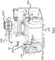
- the electric powertrain GMP comprises a gearbox housed in a gearbox CRE housing, an electric motor housed in a motor housing CME, BEP power electronics housings, and an air cooling system .
- the air cooling system includes a VENT fan located in height relative to the gearbox and the electric motor, drawing air from the outside.
- the term "height" is defined in this application in relation to the ground on which the vehicle comprising the powertrain is based. GMP.
- the axis defining this height is the z axis on the figure 1 .
- the VENT fan must be at a higher altitude than the GMP powertrain engine and gearbox to facilitate airflow. Indeed, in this embodiment of the invention, the fan VENT is allowed not to have to overcome more than 10mbar (millibar) of air pressure, so that it can operate efficiently, and provide the necessary flow (about 250m 3 per hour) at engine cooling.
- the air cooling system also includes an upstream pipe CAM channeling the air from the fan VENT to the gearbox, the air entering it through an air intake port OEA formed in the crankcase CRE of the gearbox .
- the air entering the gearbox then passes into the electric motor to cool, and then out through an air outlet port OSA formed at the end of the motor housing CME opposite the reducer.
- the air comes out in the lower part of the vehicle through a duct CAV exhaust air bringing air from the OSA outlet air outlet to the ground.
- the gearbox CRE casings and the electric motor CME are contiguous, and the BEP power electronics housings are also integrated as much as possible into the electric power train GMP, so that it can be housed perpendicularly to the front axle.
- rear of a vehicle incorporating the electric power train GMP in the engine compartment of the vehicle.
- the electric powertrain GMP thus extends in width in the engine compartment of the vehicle, and in height, which limits its vulnerability to frontal shocks.
- the interface between the crankcase CRE of the gearbox and the crankcase CME of the engine is more particularly visible on the figure 2 , which cuts in the axial direction x, parallel to the axis of rotation of an electric motor of the powertrain, the GMP electric powertrain.
- the gearbox and the electric motor are separated in their respective housings by a housing wall PCC separating the gearbox from the electric motor.
- This PCC housing wall allows air to flow along the arrows in solid lines of the figure 2 , thanks to the openings OPA air passage, present on the wall of PCC housing, and visible on the figure 3 , which cuts in a transverse direction y, orthogonal to the axis of rotation of the electric motor, the GMP electric powertrain.
- the casing wall PCC is curved towards the gearbox, and the openings OPA air passage extend radially between a bearing PSA carrier support of the rotor shaft, formed in the housing wall PCC, and the longitudinal walls PLO of the motor housing CME.
- the longitudinal walls PLO extend in the axial direction x and are substantially cylindrical. More specifically the OPA air passage holes extend from the PSA support bearing to a peripheral portion of the PCC housing wall very close to the longitudinal walls PLO, for example this peripheral portion is separated from the center of the rotor axis with a distance between 80% and 100% of the distance between this center and the longitudinal walls PLO.
- OPA air passage orifices extend angularly over a range between 15 ° and 25 °, and preferably 20 °, evenly on the housing wall PCC.
- the upstream pipe CAM is configured so that it has no radius of curvature less than 75 mm.
- the upstream pipe CAM has a radius of curvature always greater than 80 mm.
- the CAV downstream duct has no radius of curvature less than 38 mm.
- the downstream duct CAV has a radius of curvature always greater than 40 mm.
- the upstream pipe CAM Since the air intake orifice OEA of the crankcase CRE of the gearbox is narrow in the direction x, the upstream pipe CAM has a flattened section according to this direction x at its end opening on the housing CRE of the reducer. To compensate for this axial shrinkage, this end of the upstream pipe CAM and the air intake port OEA have a transverse opening in the direction y widened with respect to the diameter of the section of the upstream pipe CAM at the other end of the pipe. connected to the VENT fan.
- a bellows SO present on the downstream end portion of the upstream pipe CAM allows some flexibility to position the fan VENT on the top of the power electronics boxes BEP.
- the fan VENT is positioned in height relative to the electric motor, BEP power electronics housings, other embodiments of the invention are conceivable.
- the fan VENT is for example positioned on the gearbox.
- the upstream duct has no bellows, or has OPA air passage holes of different shape between the reducer and the electric motor.
Landscapes
- Engineering & Computer Science (AREA)
- Power Engineering (AREA)
- Chemical & Material Sciences (AREA)
- Combustion & Propulsion (AREA)
- Transportation (AREA)
- Mechanical Engineering (AREA)
- Motor Or Generator Cooling System (AREA)
- Connection Of Motors, Electrical Generators, Mechanical Devices, And The Like (AREA)
- Motor Or Generator Frames (AREA)
Description
- La présente invention se rapporte de manière générale aux domaines de l'électrotechnique et de l'automobile, et concerne plus précisément le refroidissement d'un moteur électrique de traction d'un véhicule électrique ou hybride.
- En effet dans un véhicule électrique, pour lequel le moteur électrique de traction a besoin d'être refroidi, il est possible d'utiliser un système de refroidissement à air, l'air ayant servi à refroidir le moteur devant être évacué en dehors du véhicule par un conduit d'évacuation. Ce conduit d'évacuation débouche généralement à l'air libre en partie basse du véhicule, avec le risque d'être obstrué. C'est pourquoi le brevet français
FR2983433 - Cependant un tel dispositif de protection n'est pas suffisant. En effet le système de refroidissement d'un tel véhicule comporte un ventilateur intégré au moteur électrique, c'est-à-dire partageant l'arbre rotor du moteur électrique. Ce ventilateur présente un risque de fiabilité car il aspire les poussières et les projections d'eau en provenance du conduit d'évacuation d'air du système de refroidissement. De plus, on constate que le refroidissement par air d'un tel système de refroidissement perd en efficacité du fait des pertes de charge dues notamment à la complexité du circuit d'air destiné à refroidir le moteur électrique du véhicule.
- Par ailleurs, les groupes motopropulseurs électriques de l'art antérieur présentent un encombrement important dans la direction de l'axe de rotation du moteur électrique, notamment du fait de l'encombrement du système de refroidissement du moteur. Un tel groupe motopropulseur a donc tendance à s'étendre vers l'avant dans le compartiment avant du véhicule, et à être vulnérable en cas de choc frontal.
- Du document
FR 3 000 180 A3 - Un des buts de l'invention est de remédier à au moins une partie des inconvénients de la technique antérieure en fournissant un groupe motopropulseur électrique compact et dont le refroidissement par air se fait efficacement, avec notamment un ventilateur déporté du moteur électrique et situé en hauteur par rapport à celui-ci.
- A cette fin, l'invention propose un groupe motopropulseur électrique comportant un réducteur et un moteur électrique logés dans des carters contigus, ainsi qu'un circuit de refroidissement par air dudit réducteur et dudit moteur électrique, ledit circuit de refroidissement comportant un orifice d'entrée d'air dans le carter du réducteur, des orifices de passage d'air dans une paroi de carter séparant ledit réducteur dudit moteur électrique, et un orifice de sortie d'air dans le carter dudit moteur électrique, ledit circuit de refroidissement comportant en outre un ventilateur disposé en hauteur par rapport audit réducteur et audit moteur électrique, un conduit amont canalisant l'air en provenance dudit ventilateur vers ledit réducteur , et un conduit aval d'évacuation de l'air en provenance dudit moteur électrique vers le sol.
- Grâce à l'invention, le circuit de refroidissement du moteur électrique subit moins de pertes de charge, du fait du placement en hauteur du ventilateur du système de refroidissement. Cette configuration permet également de fiabiliser le fonctionnement du ventilateur et donc de s'affranchir d'un dispositif de protection du conduit aval d'évacuation de l'air, ce qui diminue encore les pertes de charge et simplifie le système de refroidissement. Le placement en hauteur du ventilateur permet également d'économiser une protection de celui-ci aux poussières et à l'humidité. De plus grâce à la mutualisation des carters du réducteur et du moteur électrique mis pour cela bout à bout avec une paroi de carter commune laissant passer l'air, et à l'externalisation du ventilateur par rapport au moteur électrique, on obtient un groupe motopropulseur compact transversalement. Les autres éléments du groupe motopropulseur tels que son électronique de puissance pouvant être disposés verticalement par rapport au bloc réducteur et moteur, on diminue ainsi la vulnérabilité du groupe motopropulseur selon l'invention lors de chocs frontaux.
- Selon une caractéristique avantageuse du groupe motopropulseur selon l'invention, ledit ventilateur étant disposé au-dessus du carter dudit réducteur ou au-dessus du carter dudit moteur électrique, ledit conduit amont ne présente pas de rayon de courbure inférieur à 75 mm (millimètres). De même, avantageusement, ledit conduit aval ne présente pas de rayon de courbure inférieur à 38 mm.
- Une telle configuration du conduit amont et/ou aval permet de limiter au mieux les pertes de charge du circuit d'air du système de refroidissement.
- Selon une autre caractéristique avantageuse, ledit conduit amont présente une section élargie selon une direction transversale audit moteur électrique, et aplatie selon une direction axiale dudit moteur électrique, à l'entrée du carter dudit réducteur.
- Cette caractéristique permet de limiter encore les pertes de charge à l'entrée du réducteur. En effet les conduits amont et aval présentent une section communément circulaire, mais l'entrée du réducteur étant étroite dans la direction de l'axe de rotation du moteur électrique, cette section s'aplatit en entrée du réducteur selon cette direction axiale. Pour ne pas ralentir l'air à l'entrée du réducteur, on élargit donc cette section aplatie dans une direction transversale au moteur électrique, orthogonale à cette direction axiale. Cela permet également de mieux distribuer l'air arrivant dans le moteur et donc de mieux le refroidir.
- Selon encore une autre caractéristique avantageuse du groupe motopropulseur selon l'invention, lesdits orifices de passage d'air dans ladite paroi de carter s'étendent radialement entre d'une part un palier de support de l'arbre du rotor dudit moteur électrique, ledit palier étant présent dans ladite paroi de carter, et d'autre part les parois longitudinales du carter dudit moteur électrique, et angulairement sur une plage comprise entre 15° et 25°, de manière régulière sur ladite paroi de carter.
- Cette caractéristique permet un meilleur refroidissement des pièces du moteur électrique tout en gardant une bonne tenue mécanique du rotor face aux vibrations.
- Enfin avantageusement, une partie d'extrémité avale dudit conduit amont présente un soufflet apte à faciliter le positionnement dudit ventilateur.
- Cette partie du conduit amont en forme de soufflet permet éventuellement de positionner différemment le ventilateur en fonction des contraintes d'encombrement du véhicule électrique concerné.
- D'autres caractéristiques et avantages apparaîtront à la lecture d'un mode de réalisation préféré décrit en référence aux figures dans lesquelles :
- la
figure 1 représente un groupe motopropulseur électrique selon l'invention, dans ce mode de réalisation préféré, - la
figure 2 représente une coupe de ce groupe motopropulseur électrique, selon une direction axiale parallèle à l'axe de rotation d'un moteur électrique du groupe motopropulseur, - et la
figure 3 représente une autre coupe de ce groupe motopropulseur électrique, selon une direction transversale, orthogonale à l'axe de rotation du moteur électrique. - Selon un mode préféré de réalisation de l'invention représenté à la
figure 1 , le groupe motopropulseur électrique GMP selon l'invention comporte un réducteur logé dans un carter CRE de réducteur, un moteur électrique logé dans un carter CME de moteur, des boîtiers d'électronique de puissance BEP, ainsi qu'un système de refroidissement par air. - Le système de refroidissement par air comprend un ventilateur VENT situé en hauteur par rapport au réducteur et au moteur électrique, aspirant l'air de l'extérieur. Le terme « hauteur » se définit dans cette demande par rapport au sol sur lequel repose le véhicule comportant le groupe motopropulseur GMP. L'axe définissant cette hauteur est l'axe z sur la
figure 1 . Le ventilateur VENT doit donc être à plus haute altitude que le moteur et le réducteur du groupe motopropulseur GMP afin de faciliter la circulation de l'air. En effet dans ce mode de réalisation de l'invention, on permet au ventilateur VENT de ne pas avoir à vaincre plus de 10mbar (millibar) de pression d'air, afin qu'il puisse fonctionner efficacement, et apporter le débit nécessaire (environ 250m3 par heure) au refroidissement du moteur. - Le système de refroidissement par air comprend également un conduit amont CAM canalisant l'air en provenance du ventilateur VENT vers le réducteur, l'air entrant dans celui-ci via un orifice d'entrée d'air OEA ménagé dans le carter CRE du réducteur. L'air arrivant dans le réducteur passe ensuite dans le moteur électrique pour le refroidir, puis ressort par un orifice de sortie d'air OSA ménagé à l'extrémité du carter du moteur CME opposée au réducteur. L'air ressort dans la partie basse du véhicule par un conduit aval CAV d'évacuation de l'air amenant l'air en provenance de l'orifice de sortie d'air OSA vers le sol.
- Comme visible sur la
figure 1 , les carters CRE de réducteur et CME de moteur électrique sont contigus, et les boîtiers d'électronique de puissance BEP sont également intégrés le plus possible au groupe motopropulseur électrique GMP, afin que celui-ci puisse être logé perpendiculairement à l'axe avant-arrière d'un véhicule intégrant ce groupe motopropulseur électrique GMP, dans le compartiment moteur du véhicule. Le groupe motopropulseur électrique GMP s'étend ainsi en largeur dans le compartiment moteur du véhicule, et en hauteur, ce qui limite sa vulnérabilité aux chocs frontaux. - L'interface entre le carter CRE du réducteur et le carter CME du moteur est plus particulièrement visible sur la
figure 2 , qui coupe selon la direction axiale x, parallèle à l'axe de rotation d'un moteur électrique du groupe motopropulseur, le groupe motopropulseur électrique GMP. Le réducteur et le moteur électrique, non représentés, sont séparés dans leurs carters respectifs par une paroi de carter PCC séparant le réducteur du moteur électrique. Cette paroi de carter PCC permet à l'air de s'écouler selon les flèches en trait plein de lafigure 2 , grâce à des orifices de passage d'air OPA, présents sur la paroi de carter PCC, et visibles sur lafigure 3 , qui coupe selon une direction transversale y, orthogonale à l'axe de rotation du moteur électrique, le groupe motopropulseur électrique GMP. - Afin d'optimiser le refroidissement du moteur électrique tout en assurant une bonne tenue aux vibrations du rotor du moteur électrique, la paroi de carter PCC est bombée vers le réducteur, et les orifices OPA de passage d'air s'étendent radialement entre un palier de support PSA de l'arbre du rotor, ménagé dans la paroi de carter PCC, et les parois longitudinales PLO du carter CME de moteur. Les parois longitudinales PLO s'étendent selon la direction axiale x et sont sensiblement cylindriques. Plus précisément les orifices de passage d'air OPA s'étendent depuis le palier de support PSA jusqu'à une partie périphérique de la paroi de carter PCC très proche des parois longitudinales PLO, par exemple cette partie périphérique est séparée du centre de l'axe du rotor d'une distance comprise entre 80% et 100% de la distance entre ce centre et les parois longitudinales PLO.
- De plus les orifices OPA de passage d'air s'étendent angulairement sur une plage comprise entre 15° et 25°, et préférentiellement sur 20°, de manière régulière sur la paroi de carter PCC.
- Afin de faciliter l'écoulement de l'air tout le long du circuit de refroidissement du groupe motopropulseur électrique GMP, le conduit amont CAM est configuré de manière à ce qu'il ne présente pas de rayon de courbure inférieur à 75 mm. Préférentiellement le conduit amont CAM présente un rayon de courbure toujours supérieur à 80 mm.
- De même, le conduit aval CAV ne présente pas de rayon de courbure inférieur à 38 mm. Préférentiellement le conduit aval CAV présente un rayon de courbure toujours supérieur à 40 mm.
- L'orifice d'entrée d'air OEA du carter CRE du réducteur étant étroite selon la direction x, le conduit amont CAM présente une section aplatie selon cette direction x à son extrémité débouchant sur le carter CRE du réducteur. Pour compenser ce rétrécissement axial, cette extrémité du conduit amont CAM et l'orifice d'entrée d'air OEA ont une ouverture transversale selon la direction y élargie par rapport au diamètre de la section du conduit amont CAM à l'autre extrémité du conduit raccordée au ventilateur VENT.
- Par ailleurs un soufflet SO présent sur la partie d'extrémité avale du conduit amont CAM permet de disposer d'une certaine souplesse pour positionner le ventilateur VENT sur le dessus des boîtiers d'électronique de puissance BEP.
- En effet, bien que dans ce mode de réalisation préféré de l'invention, le ventilateur VENT est positionné en hauteur par rapport au moteur électrique, sur les boîtiers d'électronique de puissance BEP, d'autres modes de réalisation de l'invention sont envisageables. En variante le ventilateur VENT est par exemple positionné sur le réducteur. Dans une autre variante de réalisation de l'invention, le conduit amont ne présente pas de soufflet, ou présente des orifices de passage d'air OPA de forme différente entre le réducteur et le moteur électrique.
Claims (6)
- Groupe motopropulseur électrique (GMP) comportant un réducteur et un moteur électrique logés dans des carters contigus (CRE, CME), ainsi qu'un circuit de refroidissement par air dudit réducteur et dudit moteur électrique, ledit circuit de refroidissement comportant un orifice d'entrée d'air (OEA) dans le carter (CRE) du réducteur, des orifices de passage d'air (OPA) dans une paroi de carter (PCC) séparant ledit réducteur dudit moteur électrique, et un orifice de sortie d'air (OSA) dans le carter (CME) dudit moteur électrique, ledit circuit de refroidissement comportant en outre un ventilateur (VENT) disposé en hauteur par rapport audit réducteur et audit moteur électrique, un conduit amont (CAM) canalisant l'air en provenance dudit ventilateur (VENT) vers ledit réducteur, et un conduit aval (CAV) d'évacuation de l'air en provenance dudit moteur électrique vers le sol.
- Groupe motopropulseur (GMP) selon la revendication 1, caractérisé en ce que, ledit ventilateur (VENT) étant disposé au-dessus du carter (CRE) dudit réducteur ou au-dessus du carter (CME) dudit moteur électrique, ledit conduit amont (CAM) ne présente pas de rayon de courbure inférieur à 75 mm.
- Groupe motopropulseur (GMP) selon la revendication 1 ou 2, caractérisé en ce que ledit conduit aval (CAV) ne présente pas de rayon de courbure inférieur à 38 mm.
- Groupe motopropulseur (GMP) selon l'une quelconque des revendications 1 à 3, caractérisé en ce que ledit conduit amont (CAM) présente une section élargie selon une direction transversale audit moteur électrique, et aplatie selon une direction axiale dudit moteur électrique, à l'entrée du carter (CRE) dudit réducteur.
- Groupe motopropulseur (GMP) selon l'une quelconque des revendications 1 à 4, caractérisé en ce que lesdits orifices de passage d'air (OPA) dans ladite paroi de carter (PCC) s'étendent radialement entre d'une part un palier de support (PSA) de l'arbre du rotor dudit moteur électrique, ledit palier étant présent dans ladite paroi de carter (PCC), et d'autre part les parois longitudinales (PLO) du carter dudit moteur électrique, et angulairement sur une plage comprise entre 15° et 25°, de manière régulière sur ladite paroi de carter (PCC).
- Groupe motopropulseur (GMP) selon l'une quelconque des revendications 1 à 5, caractérisé en ce qu'une partie d'extrémité avale dudit conduit amont (CAM) présente un soufflet (SO) apte à faciliter le positionnement dudit ventilateur (VENT).
Applications Claiming Priority (2)
| Application Number | Priority Date | Filing Date | Title |
|---|---|---|---|
| FR1462016A FR3029467B1 (fr) | 2014-12-08 | 2014-12-08 | Groupe motopropulseur electrique refroidi par air |
| PCT/FR2015/052562 WO2016092162A1 (fr) | 2014-12-08 | 2015-09-25 | Groupe motopropulseur electrique refroidi par air |
Publications (2)
| Publication Number | Publication Date |
|---|---|
| EP3230102A1 EP3230102A1 (fr) | 2017-10-18 |
| EP3230102B1 true EP3230102B1 (fr) | 2018-08-01 |
Family
ID=52469144
Family Applications (1)
| Application Number | Title | Priority Date | Filing Date |
|---|---|---|---|
| EP15780928.6A Active EP3230102B1 (fr) | 2014-12-08 | 2015-09-25 | Groupe motopropulseur electrique refroidi par air |
Country Status (6)
| Country | Link |
|---|---|
| US (1) | US10358028B2 (fr) |
| EP (1) | EP3230102B1 (fr) |
| KR (1) | KR102239324B1 (fr) |
| CN (1) | CN106794750B (fr) |
| FR (1) | FR3029467B1 (fr) |
| WO (1) | WO2016092162A1 (fr) |
Families Citing this family (4)
| Publication number | Priority date | Publication date | Assignee | Title |
|---|---|---|---|---|
| FR3059359B1 (fr) * | 2016-11-29 | 2020-06-26 | Renault S.A.S | Dispositif de refroidissement d'un moyen de propulsion d'un vehicule |
| WO2019060922A1 (fr) * | 2017-09-25 | 2019-03-28 | St9 Gas And Oil, Llc | Pompe à commande électrique pour stimulation de puits |
| CA3179532A1 (fr) | 2018-04-16 | 2019-10-24 | St9 Gas And Oil, Llc | Pompe a commande electrique pour stimulation de puits |
| JP7057313B2 (ja) * | 2019-04-09 | 2022-04-19 | ファナック株式会社 | 冷却機を含む電動機を備える工作機械 |
Family Cites Families (13)
| Publication number | Priority date | Publication date | Assignee | Title |
|---|---|---|---|---|
| US3714795A (en) * | 1970-03-31 | 1973-02-06 | Tappan Co | Outdoor refrigerant apparatus |
| US3670190A (en) * | 1971-03-11 | 1972-06-13 | Robbins & Myers | Electric motor and higher speed fan assembly |
| EP0416468A1 (fr) * | 1989-09-04 | 1991-03-13 | Kabushiki Kaisha Toshiba | Moteur refroidi par air pour l'usage dans des véhicules |
| DE19547667A1 (de) * | 1995-12-20 | 1997-06-26 | Iveco Magirus | Kapselung für Fahrzeugantriebe |
| CN100460723C (zh) * | 2004-03-22 | 2009-02-11 | 通用汽车公司 | 动力系统和电动变速传动装置及消除扭矩和压力脉冲方法 |
| JP4553298B2 (ja) * | 2004-08-05 | 2010-09-29 | 本田技研工業株式会社 | 電動車両のモータ冷却構造 |
| US8100800B2 (en) * | 2008-04-04 | 2012-01-24 | GM Global Technology Operations LLC | Integrated motor cooling/clutch backfill system for use in a hybrid transmission |
| JP5331722B2 (ja) * | 2010-02-05 | 2013-10-30 | 株式会社日立製作所 | 車両の電気駆動システム |
| DE102010017222A1 (de) * | 2010-06-02 | 2011-12-08 | Ssb Wind Systems Gmbh & Co. Kg | Elektrische Antriebsanordnung |
| DE102010040491B4 (de) * | 2010-09-09 | 2012-05-31 | Siemens Aktiengesellschaft | Fahrmotor mit Kühlung |
| FR2967637B1 (fr) * | 2010-11-23 | 2012-11-16 | Peugeot Citroen Automobiles Sa | Bloc avant d'un vehicule automobile |
| FR2983433B1 (fr) | 2011-12-06 | 2014-08-29 | Renault Sa | Dispositif de protection de sortie d'un orifice d'evacuation d'air |
| FR3000180A3 (fr) * | 2012-12-26 | 2014-06-27 | Renault Sa | Systeme de refroidissement par air, notamment pour moteur electrique, et vehicule correspondant |
-
2014
- 2014-12-08 FR FR1462016A patent/FR3029467B1/fr not_active Expired - Fee Related
-
2015
- 2015-09-25 WO PCT/FR2015/052562 patent/WO2016092162A1/fr active Application Filing
- 2015-09-25 CN CN201580055794.4A patent/CN106794750B/zh active Active
- 2015-09-25 KR KR1020177018807A patent/KR102239324B1/ko active IP Right Grant
- 2015-09-25 US US15/518,938 patent/US10358028B2/en active Active
- 2015-09-25 EP EP15780928.6A patent/EP3230102B1/fr active Active
Also Published As
| Publication number | Publication date |
|---|---|
| FR3029467A1 (fr) | 2016-06-10 |
| FR3029467B1 (fr) | 2016-12-09 |
| KR20170094318A (ko) | 2017-08-17 |
| EP3230102A1 (fr) | 2017-10-18 |
| US20170225559A1 (en) | 2017-08-10 |
| US10358028B2 (en) | 2019-07-23 |
| KR102239324B1 (ko) | 2021-04-12 |
| CN106794750B (zh) | 2019-05-03 |
| CN106794750A (zh) | 2017-05-31 |
| WO2016092162A1 (fr) | 2016-06-16 |
Similar Documents
| Publication | Publication Date | Title |
|---|---|---|
| EP3077678B1 (fr) | Pulseur d'aspiration destiné à un dispositif de chauffage, ventilation et/ou climatisation d'un vehicule automobile | |
| EP3230102B1 (fr) | Groupe motopropulseur electrique refroidi par air | |
| EP1881179B1 (fr) | Système de ventilation de paroi de chambre de combustion dans une turbomachine | |
| EP3054568B1 (fr) | Moteur éléctrique avec radiateur extérieur et deux circuits de refroidissement séparés | |
| EP3212942A1 (fr) | Ventilateur centrifuge avec séparateurs de flux | |
| FR2917714A1 (fr) | Turboreacteur pour aeronef | |
| EP1779054B1 (fr) | Echangeur thermique a faisceau tubulaire, notamment pour un moteur a combustion interne suralimente | |
| EP2667030A1 (fr) | Boitier de compresseur electrique comprenant un dispositif de dissipation, et compresseur comportant un tel boitier | |
| FR3119569A1 (fr) | Module de refroidissement pour véhicule automobile électrique ou hybride à turbomachine tangentielle | |
| WO2022207837A1 (fr) | Dispositif de chauffage, ventilation et/ou climatisation pour véhicule automobile | |
| FR2793737A1 (fr) | Dispositif de chauffage et/ou climatisation d'un vehicule automobile comprenant un groupe moto-ventilateur demontable | |
| EP3714668B1 (fr) | Dispositif d'évacuation de la chaleur émise par un boîtier électronique | |
| EP3183442B1 (fr) | Conduit d'air pour le refroidissement d'un accessoire de véhicule automobile | |
| EP3942678B1 (fr) | Arbre creux de rotor divise longitudinalement comportant au moins une ailette forgee s'etendant a l'interieur | |
| EP3662166A1 (fr) | Roue de type centrifuge pour groupe moto-ventilateur | |
| FR3081387A1 (fr) | Boitier pour un appareil de chauffage, ventilation et/ou climatisation pour vehicule automobile | |
| FR3073909A1 (fr) | Volute pour groupe moto-ventilateur | |
| FR3130892A1 (fr) | Dispositif de récupération de lubrifiant dans une turbomachine | |
| EP4274756A1 (fr) | Module de refroidissement pour véhicule automobile électrique ou hybride à turbomachine tangentielle | |
| WO2009092871A1 (fr) | Appareil d'alimentation en gaz pour pile a combustible, notamment pour vehicule automobile | |
| FR3074236A1 (fr) | Groupe moto-ventilateur pour vehicule automobile | |
| FR3132468A1 (fr) | Dispositif de gestion thermique pour véhicule automobile électrique ou hybride | |
| FR2983434A1 (fr) | Support de palier dit "relais" avec moyen de protection | |
| FR3114049A1 (fr) | Ensemble de modules de refroidissement à turbomachine tangentielle pour face avant de véhicule automobile électrique ou hybride | |
| FR3073908A1 (fr) | Volute pour groupe moto-ventilateur |
Legal Events
| Date | Code | Title | Description |
|---|---|---|---|
| STAA | Information on the status of an ep patent application or granted ep patent |
Free format text: STATUS: THE INTERNATIONAL PUBLICATION HAS BEEN MADE |
|
| PUAI | Public reference made under article 153(3) epc to a published international application that has entered the european phase |
Free format text: ORIGINAL CODE: 0009012 |
|
| STAA | Information on the status of an ep patent application or granted ep patent |
Free format text: STATUS: REQUEST FOR EXAMINATION WAS MADE |
|
| 17P | Request for examination filed |
Effective date: 20170522 |
|
| AK | Designated contracting states |
Kind code of ref document: A1 Designated state(s): AL AT BE BG CH CY CZ DE DK EE ES FI FR GB GR HR HU IE IS IT LI LT LU LV MC MK MT NL NO PL PT RO RS SE SI SK SM TR |
|
| AX | Request for extension of the european patent |
Extension state: BA ME |
|
| DAV | Request for validation of the european patent (deleted) | ||
| DAX | Request for extension of the european patent (deleted) | ||
| GRAP | Despatch of communication of intention to grant a patent |
Free format text: ORIGINAL CODE: EPIDOSNIGR1 |
|
| STAA | Information on the status of an ep patent application or granted ep patent |
Free format text: STATUS: GRANT OF PATENT IS INTENDED |
|
| INTG | Intention to grant announced |
Effective date: 20180425 |
|
| GRAS | Grant fee paid |
Free format text: ORIGINAL CODE: EPIDOSNIGR3 |
|
| GRAA | (expected) grant |
Free format text: ORIGINAL CODE: 0009210 |
|
| STAA | Information on the status of an ep patent application or granted ep patent |
Free format text: STATUS: THE PATENT HAS BEEN GRANTED |
|
| AK | Designated contracting states |
Kind code of ref document: B1 Designated state(s): AL AT BE BG CH CY CZ DE DK EE ES FI FR GB GR HR HU IE IS IT LI LT LU LV MC MK MT NL NO PL PT RO RS SE SI SK SM TR |
|
| REG | Reference to a national code |
Ref country code: GB Ref legal event code: FG4D Free format text: NOT ENGLISH |
|
| REG | Reference to a national code |
Ref country code: CH Ref legal event code: EP Ref country code: AT Ref legal event code: REF Ref document number: 1023880 Country of ref document: AT Kind code of ref document: T Effective date: 20180815 |
|
| REG | Reference to a national code |
Ref country code: IE Ref legal event code: FG4D Free format text: LANGUAGE OF EP DOCUMENT: FRENCH |
|
| REG | Reference to a national code |
Ref country code: DE Ref legal event code: R096 Ref document number: 602015014411 Country of ref document: DE |
|
| REG | Reference to a national code |
Ref country code: FR Ref legal event code: PLFP Year of fee payment: 4 |
|
| REG | Reference to a national code |
Ref country code: NL Ref legal event code: MP Effective date: 20180801 |
|
| REG | Reference to a national code |
Ref country code: LT Ref legal event code: MG4D |
|
| REG | Reference to a national code |
Ref country code: AT Ref legal event code: MK05 Ref document number: 1023880 Country of ref document: AT Kind code of ref document: T Effective date: 20180801 |
|
| PG25 | Lapsed in a contracting state [announced via postgrant information from national office to epo] |
Ref country code: LT Free format text: LAPSE BECAUSE OF FAILURE TO SUBMIT A TRANSLATION OF THE DESCRIPTION OR TO PAY THE FEE WITHIN THE PRESCRIBED TIME-LIMIT Effective date: 20180801 Ref country code: IS Free format text: LAPSE BECAUSE OF FAILURE TO SUBMIT A TRANSLATION OF THE DESCRIPTION OR TO PAY THE FEE WITHIN THE PRESCRIBED TIME-LIMIT Effective date: 20181201 Ref country code: RS Free format text: LAPSE BECAUSE OF FAILURE TO SUBMIT A TRANSLATION OF THE DESCRIPTION OR TO PAY THE FEE WITHIN THE PRESCRIBED TIME-LIMIT Effective date: 20180801 Ref country code: PL Free format text: LAPSE BECAUSE OF FAILURE TO SUBMIT A TRANSLATION OF THE DESCRIPTION OR TO PAY THE FEE WITHIN THE PRESCRIBED TIME-LIMIT Effective date: 20180801 Ref country code: NL Free format text: LAPSE BECAUSE OF FAILURE TO SUBMIT A TRANSLATION OF THE DESCRIPTION OR TO PAY THE FEE WITHIN THE PRESCRIBED TIME-LIMIT Effective date: 20180801 Ref country code: BG Free format text: LAPSE BECAUSE OF FAILURE TO SUBMIT A TRANSLATION OF THE DESCRIPTION OR TO PAY THE FEE WITHIN THE PRESCRIBED TIME-LIMIT Effective date: 20181101 Ref country code: SE Free format text: LAPSE BECAUSE OF FAILURE TO SUBMIT A TRANSLATION OF THE DESCRIPTION OR TO PAY THE FEE WITHIN THE PRESCRIBED TIME-LIMIT Effective date: 20180801 Ref country code: AT Free format text: LAPSE BECAUSE OF FAILURE TO SUBMIT A TRANSLATION OF THE DESCRIPTION OR TO PAY THE FEE WITHIN THE PRESCRIBED TIME-LIMIT Effective date: 20180801 Ref country code: FI Free format text: LAPSE BECAUSE OF FAILURE TO SUBMIT A TRANSLATION OF THE DESCRIPTION OR TO PAY THE FEE WITHIN THE PRESCRIBED TIME-LIMIT Effective date: 20180801 Ref country code: NO Free format text: LAPSE BECAUSE OF FAILURE TO SUBMIT A TRANSLATION OF THE DESCRIPTION OR TO PAY THE FEE WITHIN THE PRESCRIBED TIME-LIMIT Effective date: 20181101 Ref country code: GR Free format text: LAPSE BECAUSE OF FAILURE TO SUBMIT A TRANSLATION OF THE DESCRIPTION OR TO PAY THE FEE WITHIN THE PRESCRIBED TIME-LIMIT Effective date: 20181102 |
|
| PG25 | Lapsed in a contracting state [announced via postgrant information from national office to epo] |
Ref country code: HR Free format text: LAPSE BECAUSE OF FAILURE TO SUBMIT A TRANSLATION OF THE DESCRIPTION OR TO PAY THE FEE WITHIN THE PRESCRIBED TIME-LIMIT Effective date: 20180801 Ref country code: AL Free format text: LAPSE BECAUSE OF FAILURE TO SUBMIT A TRANSLATION OF THE DESCRIPTION OR TO PAY THE FEE WITHIN THE PRESCRIBED TIME-LIMIT Effective date: 20180801 Ref country code: LV Free format text: LAPSE BECAUSE OF FAILURE TO SUBMIT A TRANSLATION OF THE DESCRIPTION OR TO PAY THE FEE WITHIN THE PRESCRIBED TIME-LIMIT Effective date: 20180801 |
|
| PG25 | Lapsed in a contracting state [announced via postgrant information from national office to epo] |
Ref country code: MC Free format text: LAPSE BECAUSE OF FAILURE TO SUBMIT A TRANSLATION OF THE DESCRIPTION OR TO PAY THE FEE WITHIN THE PRESCRIBED TIME-LIMIT Effective date: 20180801 Ref country code: EE Free format text: LAPSE BECAUSE OF FAILURE TO SUBMIT A TRANSLATION OF THE DESCRIPTION OR TO PAY THE FEE WITHIN THE PRESCRIBED TIME-LIMIT Effective date: 20180801 Ref country code: IT Free format text: LAPSE BECAUSE OF FAILURE TO SUBMIT A TRANSLATION OF THE DESCRIPTION OR TO PAY THE FEE WITHIN THE PRESCRIBED TIME-LIMIT Effective date: 20180801 Ref country code: RO Free format text: LAPSE BECAUSE OF FAILURE TO SUBMIT A TRANSLATION OF THE DESCRIPTION OR TO PAY THE FEE WITHIN THE PRESCRIBED TIME-LIMIT Effective date: 20180801 Ref country code: CZ Free format text: LAPSE BECAUSE OF FAILURE TO SUBMIT A TRANSLATION OF THE DESCRIPTION OR TO PAY THE FEE WITHIN THE PRESCRIBED TIME-LIMIT Effective date: 20180801 Ref country code: ES Free format text: LAPSE BECAUSE OF FAILURE TO SUBMIT A TRANSLATION OF THE DESCRIPTION OR TO PAY THE FEE WITHIN THE PRESCRIBED TIME-LIMIT Effective date: 20180801 |
|
| REG | Reference to a national code |
Ref country code: CH Ref legal event code: PL |
|
| REG | Reference to a national code |
Ref country code: DE Ref legal event code: R097 Ref document number: 602015014411 Country of ref document: DE |
|
| PG25 | Lapsed in a contracting state [announced via postgrant information from national office to epo] |
Ref country code: SM Free format text: LAPSE BECAUSE OF FAILURE TO SUBMIT A TRANSLATION OF THE DESCRIPTION OR TO PAY THE FEE WITHIN THE PRESCRIBED TIME-LIMIT Effective date: 20180801 Ref country code: SK Free format text: LAPSE BECAUSE OF FAILURE TO SUBMIT A TRANSLATION OF THE DESCRIPTION OR TO PAY THE FEE WITHIN THE PRESCRIBED TIME-LIMIT Effective date: 20180801 Ref country code: DK Free format text: LAPSE BECAUSE OF FAILURE TO SUBMIT A TRANSLATION OF THE DESCRIPTION OR TO PAY THE FEE WITHIN THE PRESCRIBED TIME-LIMIT Effective date: 20180801 |
|
| PLBE | No opposition filed within time limit |
Free format text: ORIGINAL CODE: 0009261 |
|
| STAA | Information on the status of an ep patent application or granted ep patent |
Free format text: STATUS: NO OPPOSITION FILED WITHIN TIME LIMIT |
|
| REG | Reference to a national code |
Ref country code: BE Ref legal event code: MM Effective date: 20180930 |
|
| REG | Reference to a national code |
Ref country code: IE Ref legal event code: MM4A |
|
| PG25 | Lapsed in a contracting state [announced via postgrant information from national office to epo] |
Ref country code: LU Free format text: LAPSE BECAUSE OF NON-PAYMENT OF DUE FEES Effective date: 20180925 |
|
| 26N | No opposition filed |
Effective date: 20190503 |
|
| PG25 | Lapsed in a contracting state [announced via postgrant information from national office to epo] |
Ref country code: IE Free format text: LAPSE BECAUSE OF NON-PAYMENT OF DUE FEES Effective date: 20180925 |
|
| PG25 | Lapsed in a contracting state [announced via postgrant information from national office to epo] |
Ref country code: CH Free format text: LAPSE BECAUSE OF NON-PAYMENT OF DUE FEES Effective date: 20180930 Ref country code: SI Free format text: LAPSE BECAUSE OF FAILURE TO SUBMIT A TRANSLATION OF THE DESCRIPTION OR TO PAY THE FEE WITHIN THE PRESCRIBED TIME-LIMIT Effective date: 20180801 Ref country code: LI Free format text: LAPSE BECAUSE OF NON-PAYMENT OF DUE FEES Effective date: 20180930 Ref country code: BE Free format text: LAPSE BECAUSE OF NON-PAYMENT OF DUE FEES Effective date: 20180930 |
|
| PG25 | Lapsed in a contracting state [announced via postgrant information from national office to epo] |
Ref country code: MT Free format text: LAPSE BECAUSE OF FAILURE TO SUBMIT A TRANSLATION OF THE DESCRIPTION OR TO PAY THE FEE WITHIN THE PRESCRIBED TIME-LIMIT Effective date: 20180801 |
|
| PG25 | Lapsed in a contracting state [announced via postgrant information from national office to epo] |
Ref country code: TR Free format text: LAPSE BECAUSE OF FAILURE TO SUBMIT A TRANSLATION OF THE DESCRIPTION OR TO PAY THE FEE WITHIN THE PRESCRIBED TIME-LIMIT Effective date: 20180801 |
|
| PG25 | Lapsed in a contracting state [announced via postgrant information from national office to epo] |
Ref country code: PT Free format text: LAPSE BECAUSE OF FAILURE TO SUBMIT A TRANSLATION OF THE DESCRIPTION OR TO PAY THE FEE WITHIN THE PRESCRIBED TIME-LIMIT Effective date: 20180801 |
|
| PG25 | Lapsed in a contracting state [announced via postgrant information from national office to epo] |
Ref country code: HU Free format text: LAPSE BECAUSE OF FAILURE TO SUBMIT A TRANSLATION OF THE DESCRIPTION OR TO PAY THE FEE WITHIN THE PRESCRIBED TIME-LIMIT; INVALID AB INITIO Effective date: 20150925 Ref country code: MK Free format text: LAPSE BECAUSE OF NON-PAYMENT OF DUE FEES Effective date: 20180801 Ref country code: CY Free format text: LAPSE BECAUSE OF FAILURE TO SUBMIT A TRANSLATION OF THE DESCRIPTION OR TO PAY THE FEE WITHIN THE PRESCRIBED TIME-LIMIT Effective date: 20180801 |
|
| P01 | Opt-out of the competence of the unified patent court (upc) registered |
Effective date: 20230608 |
|
| PGFP | Annual fee paid to national office [announced via postgrant information from national office to epo] |
Ref country code: GB Payment date: 20230920 Year of fee payment: 9 |
|
| PGFP | Annual fee paid to national office [announced via postgrant information from national office to epo] |
Ref country code: FR Payment date: 20230928 Year of fee payment: 9 Ref country code: DE Payment date: 20230920 Year of fee payment: 9 |