EP3230102B1 - Luftgekühlte elektrische antriebseinheit - Google Patents
Luftgekühlte elektrische antriebseinheit Download PDFInfo
- Publication number
- EP3230102B1 EP3230102B1 EP15780928.6A EP15780928A EP3230102B1 EP 3230102 B1 EP3230102 B1 EP 3230102B1 EP 15780928 A EP15780928 A EP 15780928A EP 3230102 B1 EP3230102 B1 EP 3230102B1
- Authority
- EP
- European Patent Office
- Prior art keywords
- electric motor
- air
- powertrain
- casing
- speed reducer
- Prior art date
- Legal status (The legal status is an assumption and is not a legal conclusion. Google has not performed a legal analysis and makes no representation as to the accuracy of the status listed.)
- Active
Links
Images


Classifications
-
- B—PERFORMING OPERATIONS; TRANSPORTING
- B60—VEHICLES IN GENERAL
- B60K—ARRANGEMENT OR MOUNTING OF PROPULSION UNITS OR OF TRANSMISSIONS IN VEHICLES; ARRANGEMENT OR MOUNTING OF PLURAL DIVERSE PRIME-MOVERS IN VEHICLES; AUXILIARY DRIVES FOR VEHICLES; INSTRUMENTATION OR DASHBOARDS FOR VEHICLES; ARRANGEMENTS IN CONNECTION WITH COOLING, AIR INTAKE, GAS EXHAUST OR FUEL SUPPLY OF PROPULSION UNITS IN VEHICLES
- B60K11/00—Arrangement in connection with cooling of propulsion units
- B60K11/06—Arrangement in connection with cooling of propulsion units with air cooling
-
- B—PERFORMING OPERATIONS; TRANSPORTING
- B60—VEHICLES IN GENERAL
- B60K—ARRANGEMENT OR MOUNTING OF PROPULSION UNITS OR OF TRANSMISSIONS IN VEHICLES; ARRANGEMENT OR MOUNTING OF PLURAL DIVERSE PRIME-MOVERS IN VEHICLES; AUXILIARY DRIVES FOR VEHICLES; INSTRUMENTATION OR DASHBOARDS FOR VEHICLES; ARRANGEMENTS IN CONNECTION WITH COOLING, AIR INTAKE, GAS EXHAUST OR FUEL SUPPLY OF PROPULSION UNITS IN VEHICLES
- B60K1/00—Arrangement or mounting of electrical propulsion units
-
- H—ELECTRICITY
- H02—GENERATION; CONVERSION OR DISTRIBUTION OF ELECTRIC POWER
- H02K—DYNAMO-ELECTRIC MACHINES
- H02K5/00—Casings; Enclosures; Supports
- H02K5/04—Casings or enclosures characterised by the shape, form or construction thereof
- H02K5/20—Casings or enclosures characterised by the shape, form or construction thereof with channels or ducts for flow of cooling medium
- H02K5/207—Casings or enclosures characterised by the shape, form or construction thereof with channels or ducts for flow of cooling medium with openings in the casing specially adapted for ambient air
-
- H—ELECTRICITY
- H02—GENERATION; CONVERSION OR DISTRIBUTION OF ELECTRIC POWER
- H02K—DYNAMO-ELECTRIC MACHINES
- H02K9/00—Arrangements for cooling or ventilating
- H02K9/02—Arrangements for cooling or ventilating by ambient air flowing through the machine
- H02K9/04—Arrangements for cooling or ventilating by ambient air flowing through the machine having means for generating a flow of cooling medium
-
- H—ELECTRICITY
- H02—GENERATION; CONVERSION OR DISTRIBUTION OF ELECTRIC POWER
- H02K—DYNAMO-ELECTRIC MACHINES
- H02K9/00—Arrangements for cooling or ventilating
- H02K9/02—Arrangements for cooling or ventilating by ambient air flowing through the machine
- H02K9/04—Arrangements for cooling or ventilating by ambient air flowing through the machine having means for generating a flow of cooling medium
- H02K9/06—Arrangements for cooling or ventilating by ambient air flowing through the machine having means for generating a flow of cooling medium with fans or impellers driven by the machine shaft
-
- B—PERFORMING OPERATIONS; TRANSPORTING
- B60—VEHICLES IN GENERAL
- B60K—ARRANGEMENT OR MOUNTING OF PROPULSION UNITS OR OF TRANSMISSIONS IN VEHICLES; ARRANGEMENT OR MOUNTING OF PLURAL DIVERSE PRIME-MOVERS IN VEHICLES; AUXILIARY DRIVES FOR VEHICLES; INSTRUMENTATION OR DASHBOARDS FOR VEHICLES; ARRANGEMENTS IN CONNECTION WITH COOLING, AIR INTAKE, GAS EXHAUST OR FUEL SUPPLY OF PROPULSION UNITS IN VEHICLES
- B60K1/00—Arrangement or mounting of electrical propulsion units
- B60K2001/003—Arrangement or mounting of electrical propulsion units with means for cooling the electrical propulsion units
- B60K2001/006—Arrangement or mounting of electrical propulsion units with means for cooling the electrical propulsion units the electric motors
Definitions
- the present invention relates generally to the fields of electrical engineering and automotive, and more specifically relates to the cooling of an electric traction motor of an electric or hybrid vehicle.
- the cooling system of such a vehicle comprises a fan integrated with the electric motor, that is to say, sharing the rotor shaft of the electric motor.
- This fan has a risk of reliability because it sucks the dust and splash water from the exhaust duct of the cooling system.
- the air cooling of such a cooling system loses efficiency due to the pressure drop due in particular to the complexity of the air circuit for cooling the electric motor of the vehicle.
- the electric powertrain of the prior art have a large footprint in the direction of the axis of rotation of the electric motor, particularly due to the size of the engine cooling system. Such a powertrain therefore tends to extend forwardly in the front compartment of the vehicle, and to be vulnerable in the event of a frontal impact.
- an electric power train comprising an electric motor housed in a housing, and an air cooling circuit of the electric motor, the cooling circuit comprising an air inlet orifice and an air outlet orifice. in the crankcase of the electric motor, the cooling circuit further comprising a fan arranged at a height relative to the electric motor, an upstream duct channeling the air from the fan towards the electric motor, and a downstream duct for evacuating the air from the electric motor to the ground.
- One of the aims of the invention is to overcome at least some of the disadvantages of the prior art by providing a compact electric powertrain and whose air cooling is done efficiently, including a remote fan of the electric motor and located in height in relation to this one.
- the invention proposes an electric powertrain comprising a gearbox and an electric motor housed in contiguous casings, and an air cooling circuit of said reducer and said electric motor, said cooling circuit comprising an orifice of air inlet into the gearbox housing, air passage holes in a housing wall separating said gearhead from said electric motor, and an air outlet port in the housing of said electric motor, said cooling circuit including in addition to a fan disposed in height relative to said reducer and said electric motor, an upstream duct channeling the air from said fan to said reducer, and a downstream duct discharging air from said electric motor to the ground.
- the cooling circuit of the electric motor undergoes less pressure losses, due to the placement of the height of the fan of the cooling system.
- This configuration also makes reliable the operation of the fan and thus to overcome a protective device of the duct downstream exhaust air, which further reduces the pressure drop and simplifies the cooling system.
- the height placement of the fan also saves dust and moisture protection.
- a powertrain is obtained. compact transversely.
- Other powertrain components such as its power electronics that can be arranged vertically relative to the gearbox and motor unit, it reduces the vulnerability of the powertrain according to the invention during frontal impacts.
- said fan being disposed above the casing of said reducer or above the casing of said electric motor, said upstream duct has no radius of curvature less than 75 mm (millimeters) . Similarly, advantageously, said downstream duct has no radius of curvature less than 38 mm.
- said upstream duct has an enlarged section in a direction transverse to said electric motor, and flattened in an axial direction of said electric motor, at the inlet of the casing of said gear.
- the upstream and downstream ducts have a commonly circular section, but the inlet of the gearbox being narrow in the direction of the axis of rotation of the electric motor, this section flattens at the input of the reducer in this axial direction. In order not to slow down the air at the inlet of the gearbox, this flattened section is thus expanded in a direction transverse to the electric motor, orthogonal to this axial direction. This also helps to better distribute the air coming into the engine and thus to cool it better.
- said air passage holes in said housing wall extend radially between on the one hand a support bearing of the rotor shaft of said electric motor, said bearing being present in said housing wall, and secondly the longitudinal walls of the housing of said electric motor, and angularly over a range of between 15 ° and 25 °, evenly on said housing wall.
- This feature allows a better cooling of the parts of the electric motor while keeping a good mechanical resistance of the rotor against vibrations.
- a downstream end portion of said upstream duct has a bellows adapted to facilitate the positioning of said fan.
- This portion of the bellows-shaped upstream duct possibly makes it possible to position the fan differently depending on the space requirements of the electric vehicle concerned.
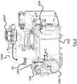
- the electric powertrain GMP comprises a gearbox housed in a gearbox CRE housing, an electric motor housed in a motor housing CME, BEP power electronics housings, and an air cooling system .
- the air cooling system includes a VENT fan located in height relative to the gearbox and the electric motor, drawing air from the outside.
- the term "height" is defined in this application in relation to the ground on which the vehicle comprising the powertrain is based. GMP.
- the axis defining this height is the z axis on the figure 1 .
- the VENT fan must be at a higher altitude than the GMP powertrain engine and gearbox to facilitate airflow. Indeed, in this embodiment of the invention, the fan VENT is allowed not to have to overcome more than 10mbar (millibar) of air pressure, so that it can operate efficiently, and provide the necessary flow (about 250m 3 per hour) at engine cooling.
- the air cooling system also includes an upstream pipe CAM channeling the air from the fan VENT to the gearbox, the air entering it through an air intake port OEA formed in the crankcase CRE of the gearbox .
- the air entering the gearbox then passes into the electric motor to cool, and then out through an air outlet port OSA formed at the end of the motor housing CME opposite the reducer.
- the air comes out in the lower part of the vehicle through a duct CAV exhaust air bringing air from the OSA outlet air outlet to the ground.
- the gearbox CRE casings and the electric motor CME are contiguous, and the BEP power electronics housings are also integrated as much as possible into the electric power train GMP, so that it can be housed perpendicularly to the front axle.
- rear of a vehicle incorporating the electric power train GMP in the engine compartment of the vehicle.
- the electric powertrain GMP thus extends in width in the engine compartment of the vehicle, and in height, which limits its vulnerability to frontal shocks.
- the interface between the crankcase CRE of the gearbox and the crankcase CME of the engine is more particularly visible on the figure 2 , which cuts in the axial direction x, parallel to the axis of rotation of an electric motor of the powertrain, the GMP electric powertrain.
- the gearbox and the electric motor are separated in their respective housings by a housing wall PCC separating the gearbox from the electric motor.
- This PCC housing wall allows air to flow along the arrows in solid lines of the figure 2 , thanks to the openings OPA air passage, present on the wall of PCC housing, and visible on the figure 3 , which cuts in a transverse direction y, orthogonal to the axis of rotation of the electric motor, the GMP electric powertrain.
- the casing wall PCC is curved towards the gearbox, and the openings OPA air passage extend radially between a bearing PSA carrier support of the rotor shaft, formed in the housing wall PCC, and the longitudinal walls PLO of the motor housing CME.
- the longitudinal walls PLO extend in the axial direction x and are substantially cylindrical. More specifically the OPA air passage holes extend from the PSA support bearing to a peripheral portion of the PCC housing wall very close to the longitudinal walls PLO, for example this peripheral portion is separated from the center of the rotor axis with a distance between 80% and 100% of the distance between this center and the longitudinal walls PLO.
- OPA air passage orifices extend angularly over a range between 15 ° and 25 °, and preferably 20 °, evenly on the housing wall PCC.
- the upstream pipe CAM is configured so that it has no radius of curvature less than 75 mm.
- the upstream pipe CAM has a radius of curvature always greater than 80 mm.
- the CAV downstream duct has no radius of curvature less than 38 mm.
- the downstream duct CAV has a radius of curvature always greater than 40 mm.
- the upstream pipe CAM Since the air intake orifice OEA of the crankcase CRE of the gearbox is narrow in the direction x, the upstream pipe CAM has a flattened section according to this direction x at its end opening on the housing CRE of the reducer. To compensate for this axial shrinkage, this end of the upstream pipe CAM and the air intake port OEA have a transverse opening in the direction y widened with respect to the diameter of the section of the upstream pipe CAM at the other end of the pipe. connected to the VENT fan.
- a bellows SO present on the downstream end portion of the upstream pipe CAM allows some flexibility to position the fan VENT on the top of the power electronics boxes BEP.
- the fan VENT is positioned in height relative to the electric motor, BEP power electronics housings, other embodiments of the invention are conceivable.
- the fan VENT is for example positioned on the gearbox.
- the upstream duct has no bellows, or has OPA air passage holes of different shape between the reducer and the electric motor.
Landscapes
- Engineering & Computer Science (AREA)
- Power Engineering (AREA)
- Chemical & Material Sciences (AREA)
- Combustion & Propulsion (AREA)
- Transportation (AREA)
- Mechanical Engineering (AREA)
- Motor Or Generator Cooling System (AREA)
- Connection Of Motors, Electrical Generators, Mechanical Devices, And The Like (AREA)
- Motor Or Generator Frames (AREA)
Claims (6)
- Elektrische Antriebseinheit (GMP), umfassend ein Getriebe und einen Elektromotor, die in aneinandergrenzenden Gehäusen (CRE, CME) untergebracht sind, sowie einen Luftkühlkreislauf des Getriebes und des Elektromotors, wobei der Kühlkreislauf eine Lufteintrittsöffnung (OEA) im Gehäuse (CRE) des Getriebes, Luftdurchtrittsöffnungen (OPA) in einer Gehäusewand (PCC), die das Getriebe von dem Elektromotor trennt, und eine Luftaustrittsöffnung (OSA) im Gehäuse (CME) des Elektromotors umfasst,
wobei der Kühlkreislauf ferner ein Gebläse (VENT), das in Bezug auf das Getriebe und den Elektromotor in der Höhe angeordnet ist, eine stromaufseitige Leitung (CAM), die die vom Gebläse (VENT) kommende Luft zum Getriebe leitet, und eine stromabseitige Leitung (CAV) zur Abführung der vom Elektromotor kommenden Luft zum Boden umfasst. - Antriebseinheit (GMP) nach Anspruch 1, dadurch gekennzeichnet, dass, während das Gebläse (VENT) oberhalb des Gehäuses (CRE) des Getriebes oder oberhalb des Gehäuses (CME) des Elektromotors angeordnet ist, die stromaufseitige Leitung (CAM) keinen Krümmungsradius von weniger als 75 mm aufweist.
- Antriebseinheit (GMP) nach Anspruch 1 oder 2, dadurch gekennzeichnet, dass die stromabseitige Leitung (CAV) keinen Krümmungsradius von weniger als 38 mm aufweist.
- Antriebseinheit (GMP) nach einem der Ansprüche 1 bis 3, dadurch gekennzeichnet, dass die stromaufseitige Leitung (CAM) am Einlass des Gehäuses (CRE) des Getriebes einen Querschnitt aufweist, der entlang einer Richtung quer zum Elektromotor aufgeweitet ist und entlang einer axialen Richtung des Elektromotors abgeflacht ist.
- Antriebseinheit (GMP) nach einem der Ansprüche 1 bis 4, dadurch gekennzeichnet, dass sich die Luftdurchtrittsöffnungen (OPA) in der Gehäusewand (PCC) radial zwischen einerseits einem Stützlager (PSA) der Welle des Rotors des Elektromotors, wobei sich das Lager in der Gehäusewand (PCC) befindet, und andererseits den Längswänden (PLO) des Gehäuses des Elektromotors und winklig über einen Bereich zwischen 15° und 25° gleichmäßig über die Gehäusewand (PCC) erstrecken.
- Antriebseinheit (GMP) nach einem der Ansprüche 1 bis 5, dadurch gekennzeichnet, dass ein stromabseitiger Endteil der stromaufseitigen Leitung (CAM) einen Faltenbalg (SO) aufweist, der geeignet ist, die Positionierung des Gebläses (VENT) zu erleichtern.
Applications Claiming Priority (2)
| Application Number | Priority Date | Filing Date | Title |
|---|---|---|---|
| FR1462016A FR3029467B1 (fr) | 2014-12-08 | 2014-12-08 | Groupe motopropulseur electrique refroidi par air |
| PCT/FR2015/052562 WO2016092162A1 (fr) | 2014-12-08 | 2015-09-25 | Groupe motopropulseur electrique refroidi par air |
Publications (2)
| Publication Number | Publication Date |
|---|---|
| EP3230102A1 EP3230102A1 (de) | 2017-10-18 |
| EP3230102B1 true EP3230102B1 (de) | 2018-08-01 |
Family
ID=52469144
Family Applications (1)
| Application Number | Title | Priority Date | Filing Date |
|---|---|---|---|
| EP15780928.6A Active EP3230102B1 (de) | 2014-12-08 | 2015-09-25 | Luftgekühlte elektrische antriebseinheit |
Country Status (6)
| Country | Link |
|---|---|
| US (1) | US10358028B2 (de) |
| EP (1) | EP3230102B1 (de) |
| KR (1) | KR102239324B1 (de) |
| CN (1) | CN106794750B (de) |
| FR (1) | FR3029467B1 (de) |
| WO (1) | WO2016092162A1 (de) |
Families Citing this family (5)
| Publication number | Priority date | Publication date | Assignee | Title |
|---|---|---|---|---|
| FR3059359B1 (fr) * | 2016-11-29 | 2020-06-26 | Renault S.A.S | Dispositif de refroidissement d'un moyen de propulsion d'un vehicule |
| WO2019060922A1 (en) | 2017-09-25 | 2019-03-28 | St9 Gas And Oil, Llc | ELECTRICALLY CONTROLLED PUMP FOR WELL STIMULATION |
| CA3179532A1 (en) | 2018-04-16 | 2019-10-24 | St9 Gas And Oil, Llc | Electric drive pump for well stimulation |
| JP7057313B2 (ja) * | 2019-04-09 | 2022-04-19 | ファナック株式会社 | 冷却機を含む電動機を備える工作機械 |
| US12459624B1 (en) | 2023-04-20 | 2025-11-04 | Brunswick Corporation | Marine drives having an electric motor assembly and methods for making the same |
Family Cites Families (13)
| Publication number | Priority date | Publication date | Assignee | Title |
|---|---|---|---|---|
| US3714795A (en) * | 1970-03-31 | 1973-02-06 | Tappan Co | Outdoor refrigerant apparatus |
| US3670190A (en) * | 1971-03-11 | 1972-06-13 | Robbins & Myers | Electric motor and higher speed fan assembly |
| EP0416468A1 (de) * | 1989-09-04 | 1991-03-13 | Kabushiki Kaisha Toshiba | Luftgekühlter Motor für die Verwendung in Fahrzeugen |
| DE19547667A1 (de) * | 1995-12-20 | 1997-06-26 | Iveco Magirus | Kapselung für Fahrzeugantriebe |
| CN100521369C (zh) * | 2004-03-22 | 2009-07-29 | 通用汽车公司 | 用于混合式机电传动装置的接线连接模块 |
| JP4553298B2 (ja) * | 2004-08-05 | 2010-09-29 | 本田技研工業株式会社 | 電動車両のモータ冷却構造 |
| US8100800B2 (en) * | 2008-04-04 | 2012-01-24 | GM Global Technology Operations LLC | Integrated motor cooling/clutch backfill system for use in a hybrid transmission |
| JP5331722B2 (ja) * | 2010-02-05 | 2013-10-30 | 株式会社日立製作所 | 車両の電気駆動システム |
| DE102010017222A1 (de) * | 2010-06-02 | 2011-12-08 | Ssb Wind Systems Gmbh & Co. Kg | Elektrische Antriebsanordnung |
| DE102010040491B4 (de) * | 2010-09-09 | 2012-05-31 | Siemens Aktiengesellschaft | Fahrmotor mit Kühlung |
| FR2967637B1 (fr) * | 2010-11-23 | 2012-11-16 | Peugeot Citroen Automobiles Sa | Bloc avant d'un vehicule automobile |
| FR2983433B1 (fr) | 2011-12-06 | 2014-08-29 | Renault Sa | Dispositif de protection de sortie d'un orifice d'evacuation d'air |
| FR3000180A3 (fr) * | 2012-12-26 | 2014-06-27 | Renault Sa | Systeme de refroidissement par air, notamment pour moteur electrique, et vehicule correspondant |
-
2014
- 2014-12-08 FR FR1462016A patent/FR3029467B1/fr not_active Expired - Fee Related
-
2015
- 2015-09-25 WO PCT/FR2015/052562 patent/WO2016092162A1/fr not_active Ceased
- 2015-09-25 US US15/518,938 patent/US10358028B2/en active Active
- 2015-09-25 KR KR1020177018807A patent/KR102239324B1/ko active Active
- 2015-09-25 CN CN201580055794.4A patent/CN106794750B/zh active Active
- 2015-09-25 EP EP15780928.6A patent/EP3230102B1/de active Active
Also Published As
| Publication number | Publication date |
|---|---|
| KR102239324B1 (ko) | 2021-04-12 |
| CN106794750B (zh) | 2019-05-03 |
| FR3029467B1 (fr) | 2016-12-09 |
| US10358028B2 (en) | 2019-07-23 |
| US20170225559A1 (en) | 2017-08-10 |
| CN106794750A (zh) | 2017-05-31 |
| EP3230102A1 (de) | 2017-10-18 |
| KR20170094318A (ko) | 2017-08-17 |
| FR3029467A1 (fr) | 2016-06-10 |
| WO2016092162A1 (fr) | 2016-06-16 |
Similar Documents
| Publication | Publication Date | Title |
|---|---|---|
| EP3230102B1 (de) | Luftgekühlte elektrische antriebseinheit | |
| CA2325722C (fr) | Dispositif de ventilation et moteur electrique de traction ferroviaire equipe d'un tel dispositif | |
| EP1881179B1 (de) | Wandbelüftungssystem für die Brennkammer einer Strömungsmaschine | |
| EP0392418B1 (de) | Vorrichtung zur Belüftung von Eisenbahnantriebsmotoren und zum Filtern von Zuführluft | |
| FR3014029A1 (fr) | Pulseur d'aspiration destine a un dispositif de chauffage, ventilation et/ou climatisation d'un vehicule automobile | |
| EP3054568B1 (de) | Elektromotor mit externem radiator und zwei getrennten kühlschaltkreisen | |
| FR2917714A1 (fr) | Turboreacteur pour aeronef | |
| WO2016066739A1 (fr) | Ventilateur centrifuge avec séparateurs de flux | |
| EP2667030A1 (de) | Gehäuse eines elektrischen Kompressors, das eine Dissipationsvorrichtung umfasst, und Kompressor mit einem solchen Gehäuse | |
| FR3119569A1 (fr) | Module de refroidissement pour véhicule automobile électrique ou hybride à turbomachine tangentielle | |
| US10563751B2 (en) | Cooling apparatus for continuously variable transmissions | |
| EP1779054B1 (de) | Wärmetauscher mit rohrkern, besonders für einen turboverbrennungsmotor | |
| WO2009092871A1 (fr) | Appareil d'alimentation en gaz pour pile a combustible, notamment pour vehicule automobile | |
| FR2793737A1 (fr) | Dispositif de chauffage et/ou climatisation d'un vehicule automobile comprenant un groupe moto-ventilateur demontable | |
| FR3074236A1 (fr) | Groupe moto-ventilateur pour vehicule automobile | |
| FR3081387A1 (fr) | Boitier pour un appareil de chauffage, ventilation et/ou climatisation pour vehicule automobile | |
| FR3130892A1 (fr) | Dispositif de récupération de lubrifiant dans une turbomachine | |
| FR3132468A1 (fr) | Dispositif de gestion thermique pour véhicule automobile électrique ou hybride | |
| WO2022207837A1 (fr) | Dispositif de chauffage, ventilation et/ou climatisation pour véhicule automobile | |
| FR3069896A1 (fr) | Roue de type centrifuge pour groupe moto-ventilateur | |
| EP4274756A1 (de) | Kühlmodul für ein elektro- oder hybridkraftfahrzeug mit einer tangentialflussturbomaschine | |
| EP3183442B1 (de) | Luftkanal zur kühlung eines zubehörteils eines kraftfahrzeugs | |
| EP3942678B1 (de) | Längsgeteilte rotorhohlwelle mit mindestens einem geschmiedeten flügel, der sich nach innen erstreckt | |
| EP3662166A1 (de) | Zentrifugalrad für motorlüftereinheit | |
| FR3095511A1 (fr) | Boîtier de mesure de particules présentes dans un flux d’air, module d’entrée d’air et une unité de chauffage, ventilation et/ou de conditionnement d’air munis d’une tel boîtier |
Legal Events
| Date | Code | Title | Description |
|---|---|---|---|
| STAA | Information on the status of an ep patent application or granted ep patent |
Free format text: STATUS: THE INTERNATIONAL PUBLICATION HAS BEEN MADE |
|
| PUAI | Public reference made under article 153(3) epc to a published international application that has entered the european phase |
Free format text: ORIGINAL CODE: 0009012 |
|
| STAA | Information on the status of an ep patent application or granted ep patent |
Free format text: STATUS: REQUEST FOR EXAMINATION WAS MADE |
|
| 17P | Request for examination filed |
Effective date: 20170522 |
|
| AK | Designated contracting states |
Kind code of ref document: A1 Designated state(s): AL AT BE BG CH CY CZ DE DK EE ES FI FR GB GR HR HU IE IS IT LI LT LU LV MC MK MT NL NO PL PT RO RS SE SI SK SM TR |
|
| AX | Request for extension of the european patent |
Extension state: BA ME |
|
| DAV | Request for validation of the european patent (deleted) | ||
| DAX | Request for extension of the european patent (deleted) | ||
| GRAP | Despatch of communication of intention to grant a patent |
Free format text: ORIGINAL CODE: EPIDOSNIGR1 |
|
| STAA | Information on the status of an ep patent application or granted ep patent |
Free format text: STATUS: GRANT OF PATENT IS INTENDED |
|
| INTG | Intention to grant announced |
Effective date: 20180425 |
|
| GRAS | Grant fee paid |
Free format text: ORIGINAL CODE: EPIDOSNIGR3 |
|
| GRAA | (expected) grant |
Free format text: ORIGINAL CODE: 0009210 |
|
| STAA | Information on the status of an ep patent application or granted ep patent |
Free format text: STATUS: THE PATENT HAS BEEN GRANTED |
|
| AK | Designated contracting states |
Kind code of ref document: B1 Designated state(s): AL AT BE BG CH CY CZ DE DK EE ES FI FR GB GR HR HU IE IS IT LI LT LU LV MC MK MT NL NO PL PT RO RS SE SI SK SM TR |
|
| REG | Reference to a national code |
Ref country code: GB Ref legal event code: FG4D Free format text: NOT ENGLISH |
|
| REG | Reference to a national code |
Ref country code: CH Ref legal event code: EP Ref country code: AT Ref legal event code: REF Ref document number: 1023880 Country of ref document: AT Kind code of ref document: T Effective date: 20180815 |
|
| REG | Reference to a national code |
Ref country code: IE Ref legal event code: FG4D Free format text: LANGUAGE OF EP DOCUMENT: FRENCH |
|
| REG | Reference to a national code |
Ref country code: DE Ref legal event code: R096 Ref document number: 602015014411 Country of ref document: DE |
|
| REG | Reference to a national code |
Ref country code: FR Ref legal event code: PLFP Year of fee payment: 4 |
|
| REG | Reference to a national code |
Ref country code: NL Ref legal event code: MP Effective date: 20180801 |
|
| REG | Reference to a national code |
Ref country code: LT Ref legal event code: MG4D |
|
| REG | Reference to a national code |
Ref country code: AT Ref legal event code: MK05 Ref document number: 1023880 Country of ref document: AT Kind code of ref document: T Effective date: 20180801 |
|
| PG25 | Lapsed in a contracting state [announced via postgrant information from national office to epo] |
Ref country code: LT Free format text: LAPSE BECAUSE OF FAILURE TO SUBMIT A TRANSLATION OF THE DESCRIPTION OR TO PAY THE FEE WITHIN THE PRESCRIBED TIME-LIMIT Effective date: 20180801 Ref country code: IS Free format text: LAPSE BECAUSE OF FAILURE TO SUBMIT A TRANSLATION OF THE DESCRIPTION OR TO PAY THE FEE WITHIN THE PRESCRIBED TIME-LIMIT Effective date: 20181201 Ref country code: RS Free format text: LAPSE BECAUSE OF FAILURE TO SUBMIT A TRANSLATION OF THE DESCRIPTION OR TO PAY THE FEE WITHIN THE PRESCRIBED TIME-LIMIT Effective date: 20180801 Ref country code: PL Free format text: LAPSE BECAUSE OF FAILURE TO SUBMIT A TRANSLATION OF THE DESCRIPTION OR TO PAY THE FEE WITHIN THE PRESCRIBED TIME-LIMIT Effective date: 20180801 Ref country code: NL Free format text: LAPSE BECAUSE OF FAILURE TO SUBMIT A TRANSLATION OF THE DESCRIPTION OR TO PAY THE FEE WITHIN THE PRESCRIBED TIME-LIMIT Effective date: 20180801 Ref country code: BG Free format text: LAPSE BECAUSE OF FAILURE TO SUBMIT A TRANSLATION OF THE DESCRIPTION OR TO PAY THE FEE WITHIN THE PRESCRIBED TIME-LIMIT Effective date: 20181101 Ref country code: SE Free format text: LAPSE BECAUSE OF FAILURE TO SUBMIT A TRANSLATION OF THE DESCRIPTION OR TO PAY THE FEE WITHIN THE PRESCRIBED TIME-LIMIT Effective date: 20180801 Ref country code: AT Free format text: LAPSE BECAUSE OF FAILURE TO SUBMIT A TRANSLATION OF THE DESCRIPTION OR TO PAY THE FEE WITHIN THE PRESCRIBED TIME-LIMIT Effective date: 20180801 Ref country code: FI Free format text: LAPSE BECAUSE OF FAILURE TO SUBMIT A TRANSLATION OF THE DESCRIPTION OR TO PAY THE FEE WITHIN THE PRESCRIBED TIME-LIMIT Effective date: 20180801 Ref country code: NO Free format text: LAPSE BECAUSE OF FAILURE TO SUBMIT A TRANSLATION OF THE DESCRIPTION OR TO PAY THE FEE WITHIN THE PRESCRIBED TIME-LIMIT Effective date: 20181101 Ref country code: GR Free format text: LAPSE BECAUSE OF FAILURE TO SUBMIT A TRANSLATION OF THE DESCRIPTION OR TO PAY THE FEE WITHIN THE PRESCRIBED TIME-LIMIT Effective date: 20181102 |
|
| PG25 | Lapsed in a contracting state [announced via postgrant information from national office to epo] |
Ref country code: HR Free format text: LAPSE BECAUSE OF FAILURE TO SUBMIT A TRANSLATION OF THE DESCRIPTION OR TO PAY THE FEE WITHIN THE PRESCRIBED TIME-LIMIT Effective date: 20180801 Ref country code: AL Free format text: LAPSE BECAUSE OF FAILURE TO SUBMIT A TRANSLATION OF THE DESCRIPTION OR TO PAY THE FEE WITHIN THE PRESCRIBED TIME-LIMIT Effective date: 20180801 Ref country code: LV Free format text: LAPSE BECAUSE OF FAILURE TO SUBMIT A TRANSLATION OF THE DESCRIPTION OR TO PAY THE FEE WITHIN THE PRESCRIBED TIME-LIMIT Effective date: 20180801 |
|
| PG25 | Lapsed in a contracting state [announced via postgrant information from national office to epo] |
Ref country code: MC Free format text: LAPSE BECAUSE OF FAILURE TO SUBMIT A TRANSLATION OF THE DESCRIPTION OR TO PAY THE FEE WITHIN THE PRESCRIBED TIME-LIMIT Effective date: 20180801 Ref country code: EE Free format text: LAPSE BECAUSE OF FAILURE TO SUBMIT A TRANSLATION OF THE DESCRIPTION OR TO PAY THE FEE WITHIN THE PRESCRIBED TIME-LIMIT Effective date: 20180801 Ref country code: IT Free format text: LAPSE BECAUSE OF FAILURE TO SUBMIT A TRANSLATION OF THE DESCRIPTION OR TO PAY THE FEE WITHIN THE PRESCRIBED TIME-LIMIT Effective date: 20180801 Ref country code: RO Free format text: LAPSE BECAUSE OF FAILURE TO SUBMIT A TRANSLATION OF THE DESCRIPTION OR TO PAY THE FEE WITHIN THE PRESCRIBED TIME-LIMIT Effective date: 20180801 Ref country code: CZ Free format text: LAPSE BECAUSE OF FAILURE TO SUBMIT A TRANSLATION OF THE DESCRIPTION OR TO PAY THE FEE WITHIN THE PRESCRIBED TIME-LIMIT Effective date: 20180801 Ref country code: ES Free format text: LAPSE BECAUSE OF FAILURE TO SUBMIT A TRANSLATION OF THE DESCRIPTION OR TO PAY THE FEE WITHIN THE PRESCRIBED TIME-LIMIT Effective date: 20180801 |
|
| REG | Reference to a national code |
Ref country code: CH Ref legal event code: PL |
|
| REG | Reference to a national code |
Ref country code: DE Ref legal event code: R097 Ref document number: 602015014411 Country of ref document: DE |
|
| PG25 | Lapsed in a contracting state [announced via postgrant information from national office to epo] |
Ref country code: SM Free format text: LAPSE BECAUSE OF FAILURE TO SUBMIT A TRANSLATION OF THE DESCRIPTION OR TO PAY THE FEE WITHIN THE PRESCRIBED TIME-LIMIT Effective date: 20180801 Ref country code: SK Free format text: LAPSE BECAUSE OF FAILURE TO SUBMIT A TRANSLATION OF THE DESCRIPTION OR TO PAY THE FEE WITHIN THE PRESCRIBED TIME-LIMIT Effective date: 20180801 Ref country code: DK Free format text: LAPSE BECAUSE OF FAILURE TO SUBMIT A TRANSLATION OF THE DESCRIPTION OR TO PAY THE FEE WITHIN THE PRESCRIBED TIME-LIMIT Effective date: 20180801 |
|
| PLBE | No opposition filed within time limit |
Free format text: ORIGINAL CODE: 0009261 |
|
| STAA | Information on the status of an ep patent application or granted ep patent |
Free format text: STATUS: NO OPPOSITION FILED WITHIN TIME LIMIT |
|
| REG | Reference to a national code |
Ref country code: BE Ref legal event code: MM Effective date: 20180930 |
|
| REG | Reference to a national code |
Ref country code: IE Ref legal event code: MM4A |
|
| PG25 | Lapsed in a contracting state [announced via postgrant information from national office to epo] |
Ref country code: LU Free format text: LAPSE BECAUSE OF NON-PAYMENT OF DUE FEES Effective date: 20180925 |
|
| 26N | No opposition filed |
Effective date: 20190503 |
|
| PG25 | Lapsed in a contracting state [announced via postgrant information from national office to epo] |
Ref country code: IE Free format text: LAPSE BECAUSE OF NON-PAYMENT OF DUE FEES Effective date: 20180925 |
|
| PG25 | Lapsed in a contracting state [announced via postgrant information from national office to epo] |
Ref country code: CH Free format text: LAPSE BECAUSE OF NON-PAYMENT OF DUE FEES Effective date: 20180930 Ref country code: SI Free format text: LAPSE BECAUSE OF FAILURE TO SUBMIT A TRANSLATION OF THE DESCRIPTION OR TO PAY THE FEE WITHIN THE PRESCRIBED TIME-LIMIT Effective date: 20180801 Ref country code: LI Free format text: LAPSE BECAUSE OF NON-PAYMENT OF DUE FEES Effective date: 20180930 Ref country code: BE Free format text: LAPSE BECAUSE OF NON-PAYMENT OF DUE FEES Effective date: 20180930 |
|
| PG25 | Lapsed in a contracting state [announced via postgrant information from national office to epo] |
Ref country code: MT Free format text: LAPSE BECAUSE OF FAILURE TO SUBMIT A TRANSLATION OF THE DESCRIPTION OR TO PAY THE FEE WITHIN THE PRESCRIBED TIME-LIMIT Effective date: 20180801 |
|
| PG25 | Lapsed in a contracting state [announced via postgrant information from national office to epo] |
Ref country code: TR Free format text: LAPSE BECAUSE OF FAILURE TO SUBMIT A TRANSLATION OF THE DESCRIPTION OR TO PAY THE FEE WITHIN THE PRESCRIBED TIME-LIMIT Effective date: 20180801 |
|
| PG25 | Lapsed in a contracting state [announced via postgrant information from national office to epo] |
Ref country code: PT Free format text: LAPSE BECAUSE OF FAILURE TO SUBMIT A TRANSLATION OF THE DESCRIPTION OR TO PAY THE FEE WITHIN THE PRESCRIBED TIME-LIMIT Effective date: 20180801 |
|
| PG25 | Lapsed in a contracting state [announced via postgrant information from national office to epo] |
Ref country code: HU Free format text: LAPSE BECAUSE OF FAILURE TO SUBMIT A TRANSLATION OF THE DESCRIPTION OR TO PAY THE FEE WITHIN THE PRESCRIBED TIME-LIMIT; INVALID AB INITIO Effective date: 20150925 Ref country code: MK Free format text: LAPSE BECAUSE OF NON-PAYMENT OF DUE FEES Effective date: 20180801 Ref country code: CY Free format text: LAPSE BECAUSE OF FAILURE TO SUBMIT A TRANSLATION OF THE DESCRIPTION OR TO PAY THE FEE WITHIN THE PRESCRIBED TIME-LIMIT Effective date: 20180801 |
|
| P01 | Opt-out of the competence of the unified patent court (upc) registered |
Effective date: 20230608 |
|
| REG | Reference to a national code |
Ref country code: DE Ref legal event code: R081 Ref document number: 602015014411 Country of ref document: DE Owner name: AMPERE S.A.S., FR Free format text: FORMER OWNER: RENAULT S.A.S., BOULOGNE BILLANCOURT, FR |
|
| PGFP | Annual fee paid to national office [announced via postgrant information from national office to epo] |
Ref country code: DE Payment date: 20240918 Year of fee payment: 10 |
|
| PGFP | Annual fee paid to national office [announced via postgrant information from national office to epo] |
Ref country code: GB Payment date: 20240920 Year of fee payment: 10 |
|
| PGFP | Annual fee paid to national office [announced via postgrant information from national office to epo] |
Ref country code: FR Payment date: 20240925 Year of fee payment: 10 |
|
| REG | Reference to a national code |
Ref country code: GB Ref legal event code: 732E Free format text: REGISTERED BETWEEN 20250501 AND 20250507 |